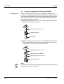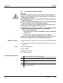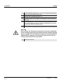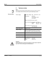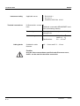
1
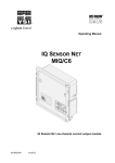
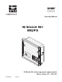
Operating Manual IQ SENSOR NET MIQ/PS OK er Pow ! IQ SENSOR NET wide-range power supply module Mains voltage 100 ... 240 VAC ba76029e01 01/2012 MIQ/PS Note For the most recent version of the manual, please visit www.ysi.com. Contact Copyright 2 YSI 1725 Brannum Lane Yellow Springs, OH 45387 USA Tel: +1 937-767-7241 800-765-4974 Email: [email protected] Internet: www.ysi.com © 2012 Xylem Inc. ba76029e01 01/2012 MIQ/PS List of contents MIQ/PS - List of contents 1 Overview . . . . . . . . . . . . . . . . . . . . . . . . . . . . . . . . . . . . 1-1 1.1 1.2 2 Safety instructions . . . . . . . . . . . . . . . . . . . . . . . . . . . . 2-1 2.1 2.2 3 Maintenance . . . . . . . . . . . . . . . . . . . . . . . . . . . . . . . . . . 4-1 Cleaning . . . . . . . . . . . . . . . . . . . . . . . . . . . . . . . . . . . . . 4-1 5 Technical data . . . . . . . . . . . . . . . . . . . . . . . . . . . . . . . 5-1 6 Contact Information . . . . . . . . . . . . . . . . . . . . . . . . . . . 6-1 6.1 6.2 01/2012 Scope of delivery . . . . . . . . . . . . . . . . . . . . . . . . . . . . . . 3-1 Installation in the IQ SENSOR NET . . . . . . . . . . . . . . . . . 3-1 Electrical connections: General instructions . . . . . . . . . 3-2 Connecting the power supply . . . . . . . . . . . . . . . . . . . . . 3-4 Maintenance and cleaning . . . . . . . . . . . . . . . . . . . . . 4-1 4.1 4.2 ba76029e01 Authorized use . . . . . . . . . . . . . . . . . . . . . . . . . . . . . . . . 2-2 General safety instructions . . . . . . . . . . . . . . . . . . . . . . . 2-2 Installation . . . . . . . . . . . . . . . . . . . . . . . . . . . . . . . . . . 3-1 3.1 3.2 3.3 3.4 4 How to use this component operating manual . . . . . . . . 1-1 Features of the MIQ/PS . . . . . . . . . . . . . . . . . . . . . . . . . 1-2 Ordering & Technical Support . . . . . . . . . . . . . . . . . . . . 6-1 Service Information . . . . . . . . . . . . . . . . . . . . . . . . . . . . 6-1 0-1 List of contents 0-2 MIQ/PS ba76029e01 01/2012 MIQ/PS Overview 1 Overview 1.1 How to use this component operating manual Structure of the IQ SENSOR NET operating manual IQ Sensor Net Operating Manual System Operating Manual (Ring Binder) IQ Sensor Operating Manual MIQ Module Operating Manual MIQ Terminal Operating Manual Component Operating Manuals Fig. 1-1 Structure of the IQ SENSOR NET operating manual. The IQ SENSOR NET operating manual has a modular structure like the IQ SENSOR NET system itself. It consists of a system operating manual and the operating manuals of all the components used. Please file these component operating manuals into the ring binder of the system operating manual. ba76029e01 01/2012 1-1 Overview MIQ/PS 1.2 General characteristics Features of the MIQ/PS The MIQ/PS wide-range power supply supplies the IQ SENSOR NET with its operational voltage. The operational voltage is forwarded to the consumers in the following ways: In the case of stacked mounting, via the IQ SENSOR NET contacts on the front and rear of the module In the case of distributed mounting, via the IQ SENSOR NET SNCIQ cable In the case of sensors, via the SACIQ sensor connecting cable. With the standard MIQ module housing, the MIQ/PS has the same characteristics as all MIQ modules regarding stability, leakproofness and weather resistance. It also provides the same wide variety of installation options (stacked mounting, canopy mounting, tophat rail mounting, etc.). The number of MIQ/PS that are required depends on the number of consumers in the system and their power requirement as well as on the overall loss of power in the IQ SENSOR NET cables. Instructions for determining the correct number of power modules are given in the INSTALLATION chapter of the system operating manual. Terminal strip The MIQ/PS has the following electrical connections on the terminal strip inside the housing: 1 x mains connection, two-pole 3 x SENSORNET connection. 1-2 ba76029e01 01/2012 MIQ/PS Safety instructions 2 Safety instructions This component operating manual contains special instructions that must be followed during the installation of the MIQ/PS power supply module. Thus, it is essential to read this component operating manual before carrying out any work with the system. In addition to this manual, the SAFETY chapter of the IQ SENSOR NET system operating manual must be followed. Always keep this component operating manual together with the system operating manual and all other component operating manuals in the vicinity of the IQ SENSOR NET system. Special user qualifications General safety instructions The MIQ/PS may only be connected to the power supply by a trained electrician. Safety instructions in this operating manual are identified by the warning symbol (triangle) in the left column. The signal word (e. g. "Caution") indicates the level of danger: Warning indicates instructions that must be followed precisely in order to prevent serious dangers to persons. Caution indicates instructions that must be followed precisely in order to avoid slight injuries or damage to the instrument or the environment. Other labels Note indicates notes that draw your attention to special features. Note indicates cross-references to other documents, e.g. operating manuals. ba76029e01 01/2012 2-1 Safety instructions MIQ/PS 2.1 Authorized use The authorized use of the MIQ/PS consists of its use as a power supply module in the IQ SENSOR NET. The technical specifications given in chapter 5 TECHNICAL DATA must be observed. Only operation according to the instructions in this component operating manual is authorized. Any other use is considered to be unauthorized. Unauthorized use invalidates any claims with regard to the guarantee. 2.2 General safety instructions The MIQ/PS is constructed and inspected in accordance with the relevant guidelines and norms for electronic instruments (see chapter 5 TECHNICAL DATA). It left the factory in a safe and secure technical condition. Function and operational safety The failure-free function and operational safety of the MIQ/PS is only guaranteed if the generally applicable safety measures and the special safety instructions in this operating manual are followed during its use. The failure-free function and operational safety of the MIQ/PS is only guaranteed under the environmental conditions that are specified in chapter 5 TECHNICAL DATA. Safe operation If safe operation is no longer possible, the MIQ/PS must be taken out of operation and secured against inadvertent operation. Safe operation is no longer possible if the MIQ/PS: has been damaged during transport has been stored under adverse conditions for a lengthy period of time is visibly damaged no longer operates as described in this manual. If you are in any doubt, contact the supplier of your MIQ/PS. 2-2 ba76029e01 01/2012 MIQ/PS Installation 3 Installation 3.1 Scope of delivery The scope of delivery of the MIQ/PS is listed in the INSTALLATION chapter of the system operating manual. 3.2 Installation in the IQ SENSOR NET The IQ SENSOR NET provides a number of options for integrating the MIQ/PS mechanically and electrically in the system (stacked mounting, distributed mounting, etc.). The individual types of installation are described in detail in the INSTALLATION chapter of the system operating manual. Note To achieve optimum heat transfer, it is recommended to always place the power supply module at the back of a module stack. Note If there are several power supply modules in the IQ SENSOR NET, it is helpful if all the power supply modules are connected to a single power supply. As a result, the system can be easily switched on and off from a single location. ba76029e01 01/2012 3-1 Installation MIQ/PS 3.3 Cable glands Electrical connections: General instructions All electric cables are fed from below via prepared openings in the enclosure of the MIQ/PS. Cable glands with different clamping ranges are included with the MIQ/PS to provide sealing between the cable and enclosure as well as for strain relief. Select the matching cable gland for the respective cable diameter: Small, clamping range 4.5 to 10 mm. This cable gland is suitable for all IQ SENSOR NET sensor cables. sealing ring 20 x 15 x 1 mm cable gland M16 blind plug Large, clamping range 7 to 13 mm. This cable gland is required for cable sheaths with an outside diameter of more than 10 mm and is screwed into the enclosure via an extension piece. sealing ring 20 x 15 x 1 mm extension piece M16/M20 sealing ring 24 x 19 x 2 mm cable gland M20 Note If necessary, you can order more large cable glands in a set of 4 pieces (Model EW/1, Order No. 480 051). 3-2 ba76029e01 01/2012 MIQ/PS Installation General installation instructions Observe the following points when attaching connecting wires to the terminal strip Shorten all wires to be used to the length required for the installation Always fit all the ends of the wires with wire end sleeves before connecting them to the terminal strip Any wires that are not used and project into the enclosure must be cut off as closely as possible to the cable gland. Screw a small cable gland with sealing ring into each remaining free opening and close it with a blind plug. Warning No free wires must be allowed to project into the enclosure. Otherwise, there is a danger that areas safe to contact could come into contact with dangerous voltages which could result in life threatening electric shock when working with the IQ SENSOR NET. Always cut off any wires that are not in use as closely as possible to the cable gland. ba76029e01 01/2012 3-3 Installation MIQ/PS 3.4 Connecting the power supply Warning If the power supply is connected incorrectly, it may represent a danger to life from electric shock. Pay attention to the following points during installation: The MIQ/PS may only be connected to the power supply by a trained electrician. The connection of the MIQ/PS to the power supply may only be carried out when it is not carrying any voltage. The power supply must fulfill the specifications given on the nameplate and in chapter 5 TECHNICAL DATA. When installed in a building, a switch or power switch must be provided as a disconnecting device for the MIQ/PS. The interrupt facility must: – be installed in the vicinity of the MIQ/PS, easily accessible by the user, and – identified as a disconnecting device for the MIQ/PS. After it has been installed, the MIQ/PS may only be opened if the mains voltage has been switched off beforehand. Materials required Wire end sleeves, suitable for the power line, with suitable crimping tool 1 x cable gland, matched to the cable diameter (see section 3.3 on page 3-2). Tools Cable stripping knife Wire stripper Phillips screw driver Small screw driver. Preparing the power line 3-4 1 Cut off the cable to the required length. 2 Strip the cable insulation for approx. 45 mm. 3 Bare the wires of phases L and N and fit them with wire end sleeves. 4 If present, cut off the protective earth conductor wire at the end of the cable sheath. ba76029e01 01/2012 MIQ/PS Installation ca. 45 mm L N cut protective conducter here Fig. 3-1 Prepared power cable. Caution The protective earth conductor must not project into the housing. Otherwise, malfunctions could occur. Connecting the power line 5 Open the module. X4 GREEN SHIELD ON X3 X2 X1 GREEN X5 SHIELD X6 RED X7 RED 100 V...240 VAC T 1,6 A X8 SN TERMINATOR X9 GREEN N SHIELD X10 L1 RED X11 OFF MAINS SENSORNET 3 SENSORNET 2 SENSORNET 1 2 1 3 N L Fig. 3-2 ba76029e01 01/2012 Connecting the power line. 3-5 Installation MIQ/PS 6 Screw the cable gland (pos. 1 in Fig. 3-2) with the sealing ring (pos. 2) into the module housing. 7 Loosen the coupling ring (pos. 3). 8 Feed the power line through the cable gland into the module housing. 9 Connect phases L and N to the terminal strip. Make sure that the cable assignment agrees with the specification on the terminal label under the terminal strip. 10 Tighten the coupling ring (pos. 3). Warning No free wires are allowed to project into the housing. Otherwise, there is a danger that safe areas could come into contact with dangerous voltages. This could lead to danger when working with the IQ SENSOR NET. Always cut off any wires that are not in use as closely as possible to the cable gland. 11 3-6 Close the module. ba76029e01 01/2012 MIQ/PS Maintenance and cleaning 4 Maintenance and cleaning 4.1 Maintenance The MIQ/PS requires no special maintenance. The general maintenance of IQ SENSOR NET components is described in the IQ SENSOR NET system operating manual. 4.2 Cleaning The cleaning of IQ SENSOR NET components is described in the IQ SENSOR NET system operating manual. ba76029e01 01/2012 4-1 Maintenance and cleaning 4-2 MIQ/PS ba76029e01 01/2012 MIQ/PS Technical data 5 Technical data Note General technical data on MIQ modules are given in the TECHNICAL DATA chapter of the IQ SENSOR NET system operating manual. Electrical data Power supply Nominal voltage: 100 ... 240 VAC ± 10 % Frequency: 50/60 Hz in accordance with IEC 60038 Mains connection2-pole, N and L Line cross-section of mains connection: Europe: 1.5 ... 4.0 mm2 USA: AWG 14 ... 12 Fuse rating on the operator side: 16 A maximum Power consumption Approx. 25 W Output voltage Max. 24 VDC via the IQ SENSOR NET (for details, see chapter TECHNICAL DATA of the IQ SENSOR NET system operating manual). Power output Max. 18 W Protection class II Overvoltage category II Instrument internal fuses 5 x 20 T 1.6 A, with UL approval Manufacturer: Littlefuse Type: Series 218 Caution If the original fuse needs to be replaced, it may only be replaced by a fuse of the same type and manufacturer. ba76029e01 01/2012 5-1 Technical data Instrument safety Terminal connections MIQ/PS Applicable norms – EN 61010-1 – UL 3111-1 – CAN/CSA C22.2 No. 1010.1 IQ SENSOR NET connec- 3 tions Additional connectable SENSORNET terminator (terminating resistor) Terminal type Screw-type terminal strip, accessible by raising the lid Terminal ranges Solid wires: Flexible wires: Cable glands Suitable for cable diameter 0.2 ... 4.0 mm2 AWG 24 ... 12 0.2 ... 2.5 mm2 4.5 ... 10 mm and 7.0 ... 13 mm Caution Only the line cross-sections specified under ELECTRICAL DATA, Seite 1 can be used for the mains connection. 5-2 ba76029e01 01/2012 MIQ/PS Contact Information 6 Contact Information 6.1 Ordering & Technical Support Telephone: (800) 897-4151 (937) 767-7241 Monday through Friday, 8:00 AM to 5:00 PM ET Fax: (937) 767-1058 Email: [email protected] Mail: YSI Incorporated 1725 Brannum Lane Yellow Springs, OH 45387 USA Internet: www.ysi.com When placing an order please have the following information available: YSI account number (if available) Model number or brief description Quantity 6.2 Name and Phone Number Billing and shipping address Purchase Order or Credit Card Service Information YSI has authorized service centers throughout the United States and Internationally. For the nearest service center information, please visit www.ysi.com and click ‘Support’ or contact YSI Technical Support directly at 800-897-4151. When returning a product for service, include the Product Return form with cleaning certification. The form must be completely filled out for an YSI Service Center to accept the instrument for service. The Product Return form may be downloaded at www.ysi.com and clicking on the ‘Support‘ tab. ba76029e01 01/2012 6-1 Contact Information 6-2 MIQ/PS ba76029e01 01/2012 1725 Brannum Lane Yellow Springs, Ohio 45387 USA +1 937-767-7241 800-765-4974 (US) FAX (937) 767-1058 Email: [email protected] Internet: www.ysi.com