1
ZETOR
You are presented with a user manual amendment which covers the operation and maintenance of a new model of
the PROXIMA series 2012.
You are kindly asked to become familiar with the contents of this manual, even though you may be experienced in
operating other tractors.
The manual contains new information and overview of how the tractor may be used in different kinds of work.
If the operating, maintenance and safety rules are observed, your new tractor will become a reliable companion for
a long time.
We wish you thousands of successful working hours.
ZETOR
Brno
1
Information about technical specifications, design, equipment, material, and external appearance is valid in the time of printing
this operator’s manual. Manufacturer reserves all rights for changes.
2
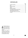
CONTENTS
Page
Location of serial numbers - tractor with a cabin ......................................................... 5
Safety instructions for users ........................................................................................ 7
Preventive daily service .............................................................................................. 9
Acquaintance with tractor .......................................................................................... 17
Operation .................................................................................................................. 47
Running-in the tractor................................................................................................ 63
Transport use ............................................................................................................ 67
Pto drive of agricultural machines ............................................................................. 75
Hydraulic system....................................................................................................... 81
Hitches ...................................................................................................................... 99
Wheel tread change ................................................................................................ 107
Additional weights ................................................................................................... 115
Electric installation .................................................................................................. 121
Tractor maintenance ............................................................................................... 129
Maintenance instructions ........................................................................................ 147
Adjustment .............................................................................................................. 167
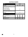
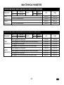
Main technical parameters ...................................................................................... 183
Index ....................................................................................................................... 205
The operator’s manual contains description, operation and maintenance of
standard and optional tractor equipment,
which can the tractor equipped with. The
option that is not a part of standard
tractor equipment cannot be a subject of
claim in case it is not assembled in the
producer’s factory. Service cheque book
is not a part of operator’s manual. This is
a separate booklet that is passed to you
at purchasing of your new tractor.
3
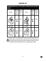
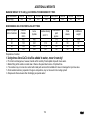
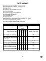
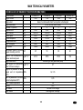
TRACTORS PROXIMA
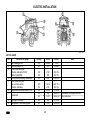
TRACTORS PROXIMA:
Tractor type
Z70
Z80
Z90
Z100
Engine output
(kW)
45
53
60
66
G1
4
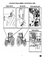
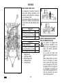
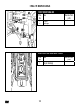
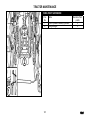
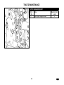
LOCATION OF SERIAL NUMBERS - TRACTOR WITH A CABIN
C10a
5
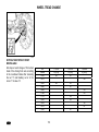
LOCATION OF SERIAL NUMBERS
When you contact your authorized service dealer or the factory for order of service parts, always give the model and serial
numbers of your tractor. For your convenience, write those numbers in the frames below.
Tractor model
Tractor serial number
Engine serial number
Zetor Proxima Z 70
Zetor Proxima Z 80
Zetor Proxima Z 90
Zetor Proxima Z 100
The “left“, “right“, “front“ and “back“ side
of the tractor is determined by travelling
direction.
Manufacturer reserves rights for changes
of design and option, that improves the
tractor features.
G3
6
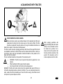
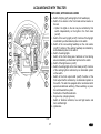
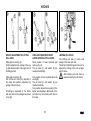
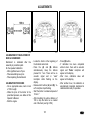
SAFETY INSTRUCTIONS FOR USERS
Keep
extreme
attention
when
reading parts of operator’s manual
that are marked by these symbols.
You will find this symbol at all
important warnings identifying
the safety of tractor operation.
Keep these regulations and be
extremely careful in these
cases!
Inform your co-operators and
other users about these messages.
Study carefully chapters marked
by this symbol before starting
with operating, servicing or
adjusting the tractor.
You will find this symbol whenever important information on
operation, adjustment and repairs of starter motor.
Keep these regulations and be
extremely careful in these
cases!
Chapters of this operator’s
manual marked by this symbol
have relation to environment
protection.
∗
This symbol indicates the tractor
accessories mounted by the
manufacturer on the customer’s
request.
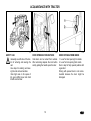
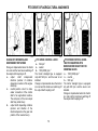
GENERAL SAFETY REGULATIONS
1.Only a trained operator having a valid
driving license and being properly
acquainted with operating and safety
rules can operate the tractor.
2.Except of safety warnings mentioned in
this operator’s manual you must respect
all general safety and traffic regulations
of country where the tractor works.
PROPER CLOTHING
3.Do not wear loose clothing and free
flying long hair.
4.Use suitable (prescribed) personal
protection means (working boots, gloves
etc.) at work.
STARTING ENGINE
5.Starting the engine when driving tractor
downhill is forbidden.
6.Starting tractor by means of towing
with another tractor or vehicle is allowed
only when the pull bar is used.
7.Start the tractor from driver’s
seat only with the shifting lever in
neutral position and with the
clutch pedal depressed-down.
Life hazard when starting by
means of starter connector short circuit.
8.The key of the key switch must be in
position "I".
9.When preheating engine by electrical
heater, plug the heater first and connect
the cable into electricity after. After
7
finishing of preheating disconnect the
cable from electricity first.
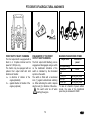
OPERATION
10.Hoses of hydrostatic steering, brakes
and fuel system must be checked and
replaced in case of any damage indication. The damage indication is for
example: cracks on hose surface,
loosening of hose fittings (it is possible to
verify it easy by pulling of hose from
fitting) and mechanical damage of hose.
It is necessary to replace the hoses with
marked service life immediately after
expiration of the marked service life.
11.Brake pedals must be latched at
transportation with trailers and implements on the road.
12.Brakes and steering must be permanently in perfect condition.
13.Driving downhill without shifted gear
is forbidden!
14.Pay special attention when driving on
hilly, muddy, sandy, icy and uneven terrain.
15.Do not exceed the max. specified
inclination angle that is max. 11°.
Respectively 12° for tractors with front
driving axle.
16.Do not exceed the max. total weight
of trailers mentioned in the tractor serial
number plate or at the rear fender.
17.Do not use the differential lock when
driving into the turning.
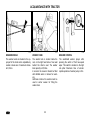
SAFETY INSTRUCTIONS FOR USERS
18.It is forbidden to get out or into the
driving tractor.
19.Reduce the travel speed to 15 km.h-1
when transporting agricultural implements hitched in the front three point
hitch.
20.The front axle load must not be lower
than 18 to 20 % of immediate total tractor set weight when transporting
agricultural implements hitched in rear
hitches.
21.Reduced gears 1R, 2R, 3R must not
be used in case that tractors Proxima 75,
85, 95 are implemented with machines
and implements having a big traction
resistance when engine speed is
dropping and the tendency of engine is
to be stopped.
22.Reduced gears 1R, 2R must not be
used in case that tractors Proxima 65 are
implemented with such machines.
TRANSPORTATION OF PERSONS,
OPERATION
23.Number of persons transported by
tractor must not exceed number
mentioned in tractor technical license.
24.Persons, that are not authorized to
work with attached implement, must not
stand between tractor and hitched
implement (machine).
25.Make sure neither any person nor any
obstacle allows driving before starting
tractor move.
26.Max. allowed travel speed of tractor
and trailer equipped with air trailer
-1
brakes is 30 km.h . Only tractor models
equipped with braked front driving axle
can travel by max. allowed speed (tractor
and trailer or semi-trailer) 40 km.h-1.
TRACTOR RESCUE AND PUSHING
27.To recover the stack tractor use a tow
bar or cable.
Never use chains! Rupture of the
chains represents a mortal danger!
28.It is life dangerous to stand near the
rope when recovering the tractor.
29.Front hook assembled on front tractor
frame serves for pulling of the tractor
alone only, i.e. without trailer or another
implement.
30.Never use free wooden blocks or bars
put between tractor and pushed subject
when pushing other vehicles (trailers,
implements etc.)
LEAVING OF TRACTOR
31.Do not park the tractor with attached
implement in lifted position.
32.Do not forget to brake the tractor with
parking brake (shift the gear), remove
the key from key switch and lock the cab
before leaving the tractor.
8
33.At tractor equipped with reversor
gear, shift the reversor lever into forward
drive position.
34.Usually use the left-hand side tractor
door when leaving the tractor. Look
round whether any vehicle is coming,
that could jeopardize your safety when
leaving the tractor.
35.Use steps and handles when leaving
the tractor. When leaving the tractor by
the right-hand side door pay attention
being in space of shifting lever and hand
throttle control.
36.Brake the tractor with parking brake
before leaving tractor with running engine.
AT STOPPED ENGINE ONLY
37.All activities connected with refuelling,
cleaning, lubricating and adjusting tractor
or attached implement can be done at
stopped engine and stopped moving
tractor parts only, except of brake,
hydraulics and charging function check.
38.It is always necessary to stop the
engine before removing of hood. The
engine can run in a closed building or
room only when sufficient ventilation
works. Exhaust gases are health
dangerous.
PRINCIPLES OF FIRE PREVENTION
39.Refuel the tractor preferentially after
finishing work and at stopped engine.
SAFETY INSTRUCTIONS FOR USERS
40.Do not refuel the fuel tank up to the
top in summer season. Wipe the fuel
immediately when spilled.
41.Do not refuel the tractor nearby open
flame and do not smoke.
42.Do not smoke and do not use open
flame when inspecting the battery
electrolyte level.
43.Keep properly the fire prevention regulations in areas with increased fire
hazard (hay-lofts, straw-stocks etc.).
44.If the tractor is equipped with a fire
extinguisher, keep it always ready for
use.
HEALTH AND ENVIRONMENT
PROTECTION
45. At the customer’s request the tractors
may be equipped with special carbon
filters of air drawn into the cabin. Without
the filters they are not suitable for work
with
aerosol
or
other
harmful
substances.
46. Tractors are not furnished with
special filters of air that is sucked to the
cab. Therefore the tractors are not
intended for work with aerosols and
other substances harmful to health.
Kerosene, diesel fuel, mineral oils and
other products from crude oil used for
operation and maintenance of tractor
may cause an injury in case of direct
contact with skin and it can irritate
mucous membranes, eyes, digestive or
respiratory organs. Some of them can
cause poisoning when swallowed.
47. The operators who enter in contact
with oil products are obliged to keep
safety
and
hygienic
instructions
consistently, make use of appropriate
protecting means, and work in wellventilated rooms.
MANIPULATION WITH CRUDEOIL PRODUCTS
48. After finishing work, wash yourself
with a non-irritant agent and treat your
hands with a suitable skin ointment or
cream.
49. When connecting and disconnecting
the quick couplers of hydraulic circuit,
remove – with a piece of any cloth – the
residual oil, which remains in the coupler
socket or possibly at the plug.
WASTE DISPOSAL
50. With disposal of the tractor or its
parts (including its operational fluids)
after termination of their service life it is
necessary to follow the applicable laws
and executing notices to the laws of the
country in which the tractor is used.
Based on the act on waste, when selling
the tractor, the final dealer of the tractor
is liable to inform the consumer about
the way of back taking of some used
9
parts of the tractor. These include oils
and other operational fluids, batteries
and tyres. Back taking of these used
products shall be carried out without any
demands for any payment from the
consumer for this back taking.
PREVENTIVE DAILY SERVICE
51. Do this service every day or at least
every 8 to 10 hours.
SAFETY CAB
52. If corrosion, crash or other accident
cause damage of the frame of safety cab
it is necessary to replace the cab.
AIR-CONDITIONING
53. In any case it is not allowed to
disassemble, turn or manipulate in
another way the screw joints of the airconditioning system, because sudden
leak of the coolant and quick local
cooling may occur. Contact or freezing of
components in hands may result in
serious injury of some tissues.
54. The air-conditioning system is
equipped with quick couplers, which
allow separation of the cab from the
tractor body if necessary, without any
leak of the coolant. Entrust the
interventions into the air conditioning
system to the service specialists.
SAFETY INSTRUCTIONS FOR USERS
ELECTRICAL INSTALLATION
55. No additional interventions
into
the
tractor
electrical
equipment (connection of other
electrical appliances) are allowed
because
of
its
possible
overloading!
56. The values of electrical installation
are:
Nominal voltage
12 V =
Ground minus pole
( - ) pole
Using of starting trucks or starting aid
devices with different voltage or polarity
causes serious failures of tractor.
57. It is necessary to be careful when
manipulating with the battery and to
avoid short circuits. Turn off the battery
switch at tractors equipped with this
switch when manipulating with the
battery.
58. Tractors must not be run with
disconnected battery, because serious
failure of tractor could occur.
10
PREVENTIVE DAILY SERVICE
Do this service every day or at least after every 8 to 10 operating hours.
G4
11
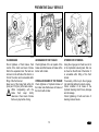
PREVENTIVE DAILY SERVICE
G5
E6g
G716c
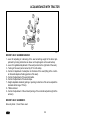
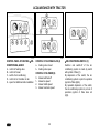
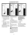
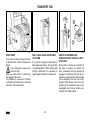
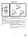
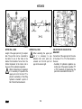
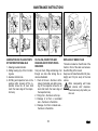
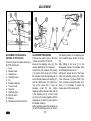
TIGHTNESS OF THE FUEL SYSTEM
Check tightness of the fuel system,
including the fuel tank discharge plug.
Eliminate immediately all leakages.
LEVEL OF OIL IN THE ENGINE
The oil gauge rod can be found on the
right side of the engine. After screwing
and pulling out the rod, check level of oil
in the engine and tightness of
connections of the engine lubrication
system. Keep level of oil between the
gauge rod marks.
COOLING SYSTEM
Check tightness of connections of the
engine cooling system and level of
cooling fluid in the expansion tank.
The expansion tank is accessible after
opening of the front bonnet. Refill the
missing volume up to the upper gauge
mark MAX. The minimum permissible
level of cooling fluid is at the gauge mark
MIN.
Release the overpressure lid
after the cooling fluid has cooled
down. Risk of scalding!
12
PREVENTIVE DAILY SERVICE
G735a
G9
G751b
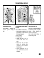
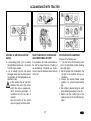
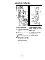
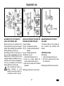
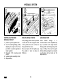
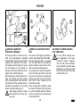
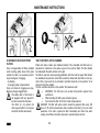
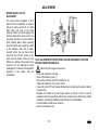
FLUID BRAKES
Check tightness of fluid brakes, fluid
control of the clutch and level of brake
fluid in the expansion tank. The tank can
be found on the left side of the tractor, in
front of the cabin and is accessible after
lifting of the front bonnet.
Keep level of the brake fluid within 3/4
(max.) and 1/2 (min.) of the tank volume.
When manipulating with the
brake
fluid,
keep
strictly
cleanness. Check level of brake
fluid every day before driving..
AIR BRAKES OF THE TRAILER
Check tightness of the air system of the
brakes and effectiveness of brakes of the
tractor with a trailer.
HYDROSTATIC STEERING
Using the oil gauge rod check level of oil
in the hydrostatic steering tank that can
be found on the left side of the tractor. It
is accessible after lifting of the front
bonnet.
If necessary, refill oil up to the oil gauge
rod mark that defines its correct volume.
Check condition of all hoses of the
hydraulic steering circuit for any damage
and oil leakage.
Check tightening of bolts and nuts of
steering rods and levers.
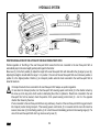
HYDRAULIC BRAKES OF THE TRAILER
Check tightness of hydraulic brakes of
the trailer and effectiveness of brakes of
the tractor with a trailer.
13
PREVENTIVE DAILY SERVICE
G11
G710b
C111
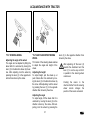
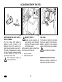
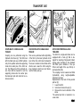
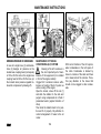
TYRES AND WHEELS
Check air pressure in the front and rear
tyres. According to nature of work, adjust
correct pressure. Check and tighten if
necessary all screws of the front and
read wheels (connection rim/disk and
disk/wheel shaft).
Never drive with loose wheel
screws!
AIR CLEANER
Maintenance of the air cleaner shall be
carried out after indication of the
indicator of clogging.
The indicator is accessible after lifting of
the bonnet. It is located close to the inlet
pipe elbow.
FILTRATION OF THE CAB
Check and clean if necessary air filters
for ventilation of the cab in the front
overhang of the roof.
Replacement of filters depends on
amount of dust in the working
environment.
Partial regeneration can be carried out
by dusting of blowing with compressed
air.
Carry out cleaning or replacement of
filter cartridges after dismounting of
cover grilles in the roof overhang.
At the customer’s request we supply
filters with active carbon.
Don’t clean the filter; don’t flush it
with compressed air.
14
PREVENTIVE DAILY SERVICE
C112
C113
G16
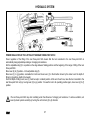
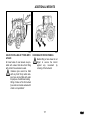
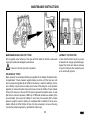
SUSPENSION EQUIPMENT
Check condition of suspension and
connection equipment including the
trailer.
AFTER WORK WITH FRONT-CARRIED
MACHINESI
After work with front-carried machines:
− Check tightness of connections of the
external hydraulic circuit for control of the
front three-point suspension.
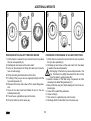
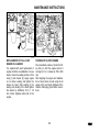
Clogging of radiators:
1. Tilt up the bonnet.
2. Release and slide out the A/C
condenser to the left side of the
tractor.
3. Clean the front walls of the engine
radiator (A/C condenser) using
compressed air (blow air in direction
from the engine).
4. Remove remaining dirt from the
space under the bonnet (to prevent its
re-sucking).
SHORT FUNCTIONAL TEST
After starting the engine check whether
the indicator of hydrostatic steering fault,
indicator of engine lubrication and
indicator of recharging are off.
Check function and tightness of
hydraulic steering circuits.
15
NOTE
16
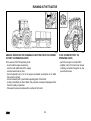
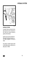
ACQUAINTANCE WITH TRACTOR
Tractor user must be properly acquainted with recommended operating
and safety rules for safe tractor operation
in advance. It is too late to do it within
operation!
Page
Safety cab ................................................................................................................. 19
Door opening from outside ........................................................................................ 19
DOor opening from inside ......................................................................................... 19
Rear window ............................................................................................................. 20
Side window .............................................................................................................. 20
∗ Tiltable roof lid ........................................................................................................ 20
∗Passenger’s seat..................................................................................................... 21
Toolbox ..................................................................................................................... 21
Right rear panel......................................................................................................... 21
Rearview mirrors ....................................................................................................... 21
Washer nozzle .......................................................................................................... 22
Washer tank .............................................................................................................. 22
Washer control .......................................................................................................... 22
Driver’s seat Mars Svratka ........................................................................................ 23
Adjustment for driver’s weight ................................................................................... 23
Longitudinal adjustment ............................................................................................ 23
Vertical adjustment.................................................................................................... 23
Driver’s seat grammer maximo ................................................................................. 24
Driver’s seat grammer s ............................................................................................ 24
*Air filter with active carbon ....................................................................................... 25
Control panel of heating, ∗air-conditioning, ∗radio .................................................... 26
Control of heating valve (A)....................................................................................... 26
Control of blower (B) ................................................................................................. 26
∗Air-conditioning switch (C)....................................................................................... 26
Control of air circulation in cab (D) ............................................................................ 27
Right function of heating and air-conditioning system ............................................... 27
Fast heating the cab space ....................................................................................... 27
Fast cooling the cab space........................................................................................ 28
Operation of heating or air-conditioning during operation of tractor .......................... 28
Immediately after cooling down the cab .................................................................... 29
Heating and airconditioning outlets ........................................................................... 30
Defrosting the front windshield .................................................................................. 30
17
ACQUAINTANCE WITH TRACTOR
Page
Control panel on right cab pillar ................................................................................ 30
*Tilt steering wheel.................................................................................................... 31
*Tilt and telescope steering wheel ............................................................................ 31
Dashboard ................................................................................................................ 33
Digital dashboard ...................................................................................................... 35
Display of pto speed ................................................................................................. 36
Switchers, switches and levers ................................................................................. 37
Light switch (a).......................................................................................................... 38
Switch of grill and cab headlight (b) .......................................................................... 38
Warning light switch (e)............................................................................................. 38
Front wheel drive switch (f) ....................................................................................... 39
Push button of rear, front differential locks (j)............................................................ 39
Turn signal, headlight and horn toggle switch (k)...................................................... 39
Ignition box ............................................................................................................... 40
Key in "0" position ..................................................................................................... 40
Key in "I" position ...................................................................................................... 40
Key in "II" position ..................................................................................................... 41
Lever of manual refulation of fuel.............................................................................. 41
PedalS and levers..................................................................................................... 42
Gear shifting lever..................................................................................................... 43
Gear shifting scheme ................................................................................................ 43
Lever of shifting of road and reduced gears.............................................................. 43
PTO selection control lever ....................................................................................... 44
∗ PTO speed control lever ....................................................................................... 44
∗ PTO speed control lever - Tractor equipped with reversor or reductor for creeping gears ................................................................................................................... 44
∗ Shifting lever of creeping speed reductor ............................................................... 45
∗ Reversor shifting lever ........................................................................................... 45
Parking brake lever, PTO shaft control lever and pick up hitch control lever .................. 45
Switching on the front output shaft zuidberg ............................................................. 46
Battery switch............................................................................................................ 46
Fuel tank ................................................................................................................... 46
Draining plug of fuel tank .......................................................................................... 46
18
ACQUAINTANCE WITH TRACTOR
C12
C120
C121
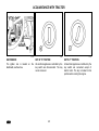
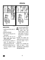
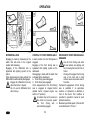
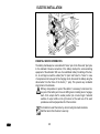
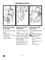
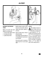
SAFETY CAB
Generally use left side of the tractor for entering and leaving the
cab.
Use steps for entering and leaving the cab and use handles.
Take high care in the space of
the gear shifting lever and hand
throttle control lever.
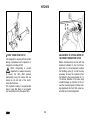
DOOR OPENING FROM OUTSIDE
Cab doors can be locked from outside.
After unlocking depress the lock button
and by pulling the handle open the door.
DOOR OPENING FROM INSIDE
1. Lever for door opening from inside
2. Lever for lock opening from inside
Door is kept in fully opened position with
a gas strut.
Driving with opened door is not recommended because the door might be
damaged.
19
ACQUAINTANCE WITH TRACTOR
C122
C123
C124
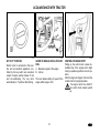
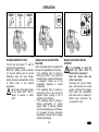
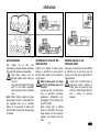
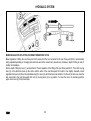
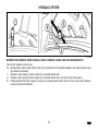
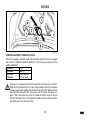
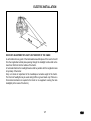
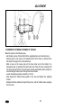
REAR WINDOW
Rear window is equipped with handle
and is kept in the open position by gas
struts.
We recommend to latch the window in closed position when driving on uneven terrain - danger of
window cracking. Before starting
work with machines implemented
in the rear three point hitch be
sure that the interference between hitched implement and
opened rear window is avoided at
the maximum lifting of the rear
three point hitch. In case of interference we recommend to work
with closed window.
SIDE WINDOW
A plastic latch locks the side window in
half-opened position.
∗ TILTABLE ROOF LID
The tiltable roof lid can be opened by
turning the arresting lever and by halfopening.
Tractor total height is increased
when opened lid. Therefore always close the lid when passing
through low profiles or when
parking there.
20
ACQUAINTANCE WITH TRACTOR
C125
C126
C127
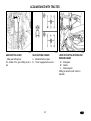
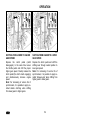
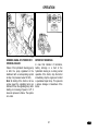
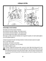
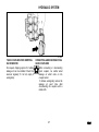
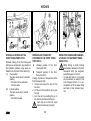
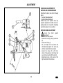
∗PASSENGER’S SEAT
Passenger’s seat (1) is tiltable and is
situated on the left cab fender.
For facilitating the access to the driver’s
seat, it is possible to tilt the passenger’s
seat upwards.
RIGHT REAR PANEL
The right rear panel includes a storage
place for a PET bottle (1), socket 12V (2)
and cigarette lighter (3).
REARVIEW MIRRORS
Adjust rearview mirrors before driving or
starting the job to be able to see the entire road or the working field.
TOOLBOX
The toolbox (2) is situated at the left side
of the driver’s seat.
21
ACQUAINTANCE WITH TRACTOR
C128
E111
C130
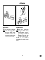
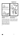
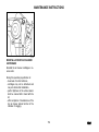
WASHER NOZZLE
The washer nozzle is situated in the upper part of the hood and is adjustable by
needle or steel wire of maximum diameter 0,8 mm.
WASHER TANK
The washer tank is located inside the
cab, on the right hand side of rear wall
behind the driver’s seat. The washer
tank capacity is 2,5 litres.
In summer the reservoir should be filled
with distilled water or mixture for washers.
Antifreeze mixture for washers must be
used in winter season for filling the
washer tank.
WASHER CONTROL
The windshield washer sprays after
pressing the switch of front two-speed
wiper. This switch is located on the right
cab pillar. Maximum time of uninterrupted operation of washer pump is 20 s.
22
ACQUAINTANCE WITH TRACTOR
C131
C132
C133
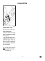
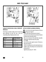
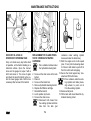
DRIVER’S SEAT Mars Svratka
ADJUSTMENT FOR DRIVER’S
WEIGHT
The suspended seat is adjustable for
driver’s weight from 50 up to 120 kg. Adjustment is done by turning of square
knob. Weight indicator is located in the
slot of rear seat cover. Spring stroke is
120 mm.
Do not adjust the seat when driving!
Danger of accident!
LONGITUDINAL ADJUSTMENT
The seat can be longitudinally adjusted
within range ± 75 mm (11 positions) after
unlocking of left hand side lever.
VERTICAL ADJUSTMENT
Vertical seat adjustment is done by the
right hand side lever; from the middle
position to two marginal positions within
range ± 30 mm.
23
ACQUAINTANCE WITH TRACTOR
E116
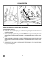
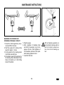
DRIVER’S SEAT GRAMMER MAXIMO
1 - Lever for adjusting of cushioning of the seat according weight of the driver (adjustment by turning in direction as shown on the pictogram on the seat bellow).
2 - Lever of longitudinal adjustment of the seat (located on the right side of the seat).
3 - Turning of the seat (can be turned by 20° to both sides).
4 - Control of adjustment of absorption of vibrations of the seat (tilting of the controller forwards adjusts a floating position of the seat).
5 - Control of adjustment of the seat inclination.
6 - Control of adjustment of the back shape.
7 - Height-adjustable backrest (pulling or pushing in direction of the arrow adjusts the
backrest within range 170mm).
8 - Tiltable armrest.
9 - Control of adjustment of the armrest (turning of the controller adjusts height of the
armrest).
DRIVER’S SEAT GRAMMER S
Here only items 1, 2 and 5 are used.
24
ACQUAINTANCE WITH TRACTOR
E730a
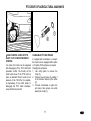
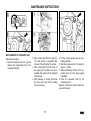
*AIR FILTER WITH ACTIVE CARBON
Filters with active carbon are installed instead of the standard dust filter and
replacement is carried out in the same way as in the common filters. The filter
should be located with the white surface on the grid. Installation directions are
stated in the chapter “Instructions for Maintenance”.
The filter is used only when spraying pesticides, after the work the paper filter should
be reinstalled, because the carbon filter would be choked with dust after a short period of time. Upon work the re-circulation controller should be in the position “air is
drawn into from the outside”.
The fan controller should be in the position “fan maximum work”.
•
WARNING: The filter does not provide full protection against toxic substances.
•
When handling the filter, wear protective gloves.
•
Don’t clean the filter; don’t flush it with compressed air.
DANGER: The filter with active carbon should be replaced after every 200 hours or
36 months (manufacture date is stated on the filter). If you can smell pesticides in the
cabin, replace the filter immediately and check the cabin sealing. Used filters should
be disposed in special disposal centres.
25
When spraying pesticides and
using the heating filter with active
carbon, the re-circulation controller should be in position “air is
drawn into from the outside” and
the fan controller should be in the
position “fan maximum work” to
create overpressure in the cabin.
ACQUAINTANCE WITH TRACTOR
C137
CONTROL PANEL OF HEATING, ∗AIRCONDITIONING, ∗RADIO
A - control of heating valve
B - control of blower
C - switch of air-conditioning
D - control of air circulation in cab
E - space for additional radio installation
C138
CONTROL OF HEATING VALVE (A)
a - heating valve closed
b - heating valve open
CONTROL OF BLOWER (B)
0 - blower switched-off
1 - blower low speed
2 - blower middle speed
3 - blower maximum speed
26
C139
∗AIR-CONDITIONING SWITCH (C)
Switch-in and switch-off of the airconditioning system is made by switch
with symbol of flake (C).
By depression of the switch, the airconditioning system is put into operation
(symbol of flake lights).
By repeated depression of the switch,
the air-conditioning system is put out of
operation (symbol of flake does not
light).
ACQUAINTANCE WITH TRACTOR
C140
G121
C142
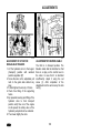
CONTROL OF AIR CIRCULATION IN
CAB (D)
a - surrounding (outer ) air is sucked
through filters into the cab - air suction
from the cab is closed.
b - air is sucked from the cab space
and again blown into the cab (inner air
re-circulation for fast temperature adaptation in cab).
In this position the air inlet from
outside of the cab is fully closed
and in the cab no overpressure,
which prevents penetration of
non-filtered air into the cab, is
created!
Use this position of the control
only for urgently necessary time!
RIGHT FUNCTION OF HEATING AND
AIR-CONDITIONING SYSTEM
It is necessary to create overpressure in
the cab for proper function of heating or
air-conditioning. Therefore we recommend to shut all windows, doors and cab
roof cover.
FAST HEATING THE CAB SPACE
Process in the following way:
1 - Turn the control of the heating valve
(A) to the right-hand position (heating
valve fully open).
2 - Set the control of air circulation in the
cab (D) to the position of inner recirculation.
3 - Choose the desired blower speed
(position 1, 2, 3) by the blower switch
(B).
4 - Set outlets to desired angle to avoid
direct blowing to persons in the cab.
5 - Switch over the control lever of the
heating valve (A) to the left-hand position.
27
ACQUAINTANCE WITH TRACTOR
C143
C144
FAST COOLING THE CAB SPACE
Process in the following way:
1 - Set the control of air circulation in the
cab (D) to the position of inner recirculation.
2 - Choose the desired blower speed
(position 1, 2, 3) by the blower switch
(B).
3 - Switch-in the air-conditioning system
by the switch (C).
4 - Set outlets to desired angle to avoid
direct blowing to persons in the cab
(possible illness because of intensive
cooling of parts of persons bodies).
OPERATION OF HEATING OR AIRCONDITIONING DURING OPERATION
OF TRACTOR
With inner air re-circulation switched-in,
the inlet of fresh air is closed and it
comes to breathing-up of cab space by
the operators. This state can cause feelings of tiredness.
Note: When working, set the control (D)
according to your individual requirements
at temperature in a position between (a)
and (b) so that the blower could suck air
from outside of the cab through the filters.
28
When spraying pesticides and
using the heating filter with active
carbon, the re-circulation controller should be in position “air is
drawn into from the outside” and
the fan controller should be in the
position “fan maximum work” to
create overpressure in the cabin.
ACQUAINTANCE WITH TRACTOR
C145
IMMEDIATELY AFTER COOLING
DOWN THE CAB
Immediately after cooling down the cab
and reduction of the inner temperature to
desired level we recommend:
− Switch over the control of air circulation
(D) from position (b - air re-circulation)
to position (a - outer air suction)
− Perform fluent regulating of air temperature
with
switched-in
airconditioning by means of half-opening
of the heating valve (A). At this setting,
air going into the cab from the outlets
is not dried so intensively.
− You can perform fluent regulating of air
temperature with switched-in airconditioning by means of decreasing
of blower power by switching the control (B) to position 1 or 2.
29
ACQUAINTANCE WITH TRACTOR
C146
P11NH127a
DEFROSTING THE FRONT WINDSHIELD
B - For fast defrosting of the front windshield direct the middle outlets of heating (3)
with angle of ca 45° towards the windshield. Direct the side outlets (4) with angle
of ca 45° towards the cab corners.
After defrosting of the front windshield, direct the side outlets to towards the side
glasses of the doors and defrost the glasses step by step. After defrosting, the
outlets should be adjusted to such direction so that air could not directly blow to
the driver but down to driver’s legs.
CONTROL PANEL ON RIGHT CAB
PILLAR
6 - switch of front working lights on cab
roof
7 - switch of rear working lights on cab
roof
8 - rear window wiper switch
9 - two-position switch of the windscreen
wiper and washer
10 *rear mirrors heating switch
11 *rear window defroster switch
HEATING AND AIRCONDITIONING OUTLETS
A - Adjustable outlets of heating (2) and ∗air-conditioning (1).
30
ACQUAINTANCE WITH TRACTOR
W1
*TILT STEERING WHEEL
Adjusting the angle of the wheel
The angle can be adjusted by tilting the
wheel after it is unlocked by moving the
lever (1) in the direction shown by the arrow. After adjusting, lock the wheel by
pressing the lever (1) in the opposite direction than shown by the arrow.
F205
*TILT AND TELESCOPE STEERING
WHEEL
Tilt column of the steering wheel enables
to adjust the angle and height of the
wheel.
Adjusting the height
To adjust height, pull the wheel up or
push it down after it is unlocked by moving the lever (1) in the direction shown by
the arrow. After adjusting, lock the wheel
by pressing the lever (1) in the opposite
direction than shown by the arrow.
Adjusting the angle
To adjust angle, tilt the wheel after it is
unlocked by moving the lever (2) in the
direction shown by the arrow. After adjusting, lock the wheel by pressing the
31
lever (2) in the opposite direction than
shown by the arrow.
After adjusting, tilt the lever (2)
towards the dashboard and the
lever (1) in such a way so that it
is parallel to the steering wheel
column axis.
Pushing the levers in the
direction farther from the steering
wheel column changes the
position of the levers as desired.
ACQUAINTANCE WITH TRACTOR
B21b
32
ACQUAINTANCE WITH TRACTOR
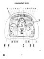
DASHBOARD
DESCRIPTION OF INSTRUMENTS
A - Indicator lights
B - Air pressure gauge
C - Speed indicator with counter of operational hours of the engine and
symbols indicating speed of the engine, at which nominal speed of the
rear output shaft is reached
depending on speed on the rear
output shaft.
D - Fuel-content gauge
E - Cooling fluid thermometer
INDICATOR LIGHTS
1. High beams (blue). Indicate that high
beams are on.
2. Indicator of direction indicator lights
(green)
3. Indicator of direction indicator lights
of the 1st trailer (green)
4. Indicator of direction indicator lights
of the 2nd trailer (green)
5. Indicator of minimal air pressure in
the brake system (red). Indicated a
drop of air pressure for air brakes of
the trailer under critical value, i.e.
450kPa.
6. Manual brake (red). Indicates applied
manual brake.
7. Recharging (red). During run of the
engine it is on in case of a fault in recharging. It must be permanently on
when the engine is stopped.
8. Indicator of lubrication (red). During
run of the engine it shall be on if
pressure of oil drops under 120 to
60kPa an on if engine is stopped.
9. Reserve.
10. Reserve.
11. Reserve.
12. Reserve
13. Reserve.
14. This indicator (red) indicates a fault
in the steering hydrostatic system.
33
15. Fuel (orange). It is on when level of
fuel in the fuel tank drops under 1/6
to 1/10 of its volume.
16. Indicator of disengagement of the
output shaft clutch (red).
17. Glow plug (yellow). Indicates activation of the device for facilitation of
start of the engine.
18. Reserve.
19. Reserve.
20. Warning indicator (red). It is on in
case of an air pressure drop under a
critical value, i.e. 450kPa, with engaged parking brake, with charging
failure or with low pressure of oil in
the engine.
21. Reserve
ACQUAINTANCE WITH TRACTOR
F54d
34
ACQUAINTANCE WITH TRACTOR
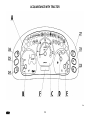
DIGITAL DASHBOARD
A digital dashboard is installed upon request.
DESCRIPTION OF INSTRUMENTS
A - Indicators
B – Air pressure gauge
C – Engine speed indicator
D – Fuel-content gauge
E – Cooling fluid thermometer
F – Display
INDICATORS & PUSHBUTTONS
Layout of the indicators on the digital
dashboard is identical with analog dashboard.
After pressing the selected pushbutton
the display shows the respective symbol
and value.
22. Battery voltage button: The voltage
value is displayed on the display
(with the resolution of 0.1 V).
23. . Button of the number of covered
kilometres (per day or since the last
reset). The number of kilometres is
shown on the display. The value can
be reset with long pressing of the button.
24. Button of immediate travel speed
in km.h-1, which is displayed on the
display
25. Free
26. PTO button. The rpm value with the
resolution of 10 rpm is shown on the
display.
Serves only for operation data
display
27. The switch of hours of operation. The
information is displayed on the display
35
ACQUAINTANCE WITH TRACTOR
F54e
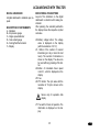
DISPLAY OF PTO SPEED
By pressing the switch marked with the arrow, you will display the PTO speed in the
left and right parts of the display. It is a number of revolutions with engaged PTO
independent revolutions.
By pressing the buttons gradually, you will induced the number of PTO revolutions for
individual gears of PTO revolutions.
A - for 1000 revolutions
B - for 540 revolutions
C - for 540E revolutions
The button serves only for displaying data.
36
ACQUAINTANCE WITH TRACTOR
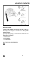
SWITCHERS, SWITCHES AND LEVERS
a - Switch of lighting (off, parking lights, front headlamps).
b - Switch of low beams in the front mask and low beams on
the cab.
∗ Option: the lights on the cab may be controlled by this
switch independently on the lights in the front mask
(on/off).
c - Switch of the rear fog light (on/off). Function of the fog light
is indicated by an illuminated symbol on the switch.
d - Switch of the rear working headlamp on the cab column
(on/off). Function of the working headlamp is indicated by
an illuminated symbol on the switch.
e - Switch of warning lights.
f - Switch of the front driving axle. Switched on front driving
axle is indicated by an illuminated symbol on the switch.
g - Switch of the light beacon (on/off).
h - Switch of working lights in the front mask (on/off). Function
of the working lights is indicated by an illuminated symbol
on the switch.
i - Switch of the front output shaft (on/off). Function of the
front output shaft is indicated by an illuminated symbol on
the switch. The switch is equipped with a mechanical catch
against unintentional switching. When switching on press
the catch towards the symbol.
j - Pushbutton of the differential lock.
k - Engine stop (stopping device).
l - Switch of direction indicators, low and high beams and
horn and flash light.
m - Ignition box.
C152
37
ACQUAINTANCE WITH TRACTOR
C153
C154
C155
LIGHT SWITCH (a)
a - Lights are “OFF“
b - Clearance lights and tail lights, license plate light and illumination of
instruments are “ON“
c - All electrical appliances are connected as in “b“ position. Moreover
low and high beam lamps are ”ON”
(according to the position of toggle
switch - turn signal, horn, lights, high
and low beam headlight switch and
acoustic horn)
SWITCH OF GRILL AND CAB
HEADLIGHT (b)
a - Cab roof headlights are “OFF”
b - Cab roof headlights are “ON”
The switch controls the headlights in the
mask grill or in the tractor cab roof. Use
the cab roof headlights only if the front
grill headlights are covered by attached
implement fitted in the front three point
hitch. Symbol on the switch indicates
that cab roof headlights are “ON”. High
beam can light in the grill only.
WARNING LIGHT SWITCH (e)
a - Warning lights are “OFF“
b - Warning lights are “ON“
Flashing of indicator light on the
dashboard indicates function of warning
lights.
38
ACQUAINTANCE WITH TRACTOR
C156
C157
C158
FRONT WHEEL DRIVE SWITCH (f)
Use the front driving axle for increasing the pulling force of the
tractor when rear wheels slip.
a - Front driving axle disengaged
b - Front driving axle engaged
Front driving axle is engaged at stopped
tractor (braked tractor; stopped engine,
switch key is switched-of).
In the basic position, the front driving
axle is engaged (indicator lamp is “ON”)
and disengaging of the axle is made with
the switch (indicator lamp is “OFF”).
PUSH BUTTON OF REAR, FRONT
DIFFERENTIAL LOCKS (j)
a - Differential lock disengaged
b - Differential lock engaged
The differential lock is engaged by pressing the differential lock push button that
returns into the previous position after
loosing. Illuminating of the symbol on the
switch indicates that the differential lock
is engaged.
The differential lock is automatically disengaged after pressing the brake pedals.
At tractors equipped with front driving
axle equipped with engageable differential lock, this is engaged simultaneously
with the rear differential lock engaging.
TURN SIGNAL, HEADLIGHT AND
HORN TOGGLE SWITCH (k)
a - Acoustic horn – press the toggle
switch in axis direction
b - Low beam light
c - Turn signal - right
d - Turn signal - left
e - Light horn
f - High beam light
39
ACQUAINTANCE WITH TRACTOR
C159
C160
C161
IGNITION BOX
The ignition box is located on the
dashboard, see the arrow.
KEY IN "0" POSITION
All electrical appliances controlled by the
key switch are disconnected. The key
can be removed.
KEY IN "I" POSITION
All electrical appliances controlled by the
key switch are connected except of
starter motor. The key is located in this
position when running the engine.
40
ACQUAINTANCE WITH TRACTOR
C162
KEY IN "II" POSITION
Starter motor is connected in this position and all electrical appliances controlled by the key switch are connected
except of wipers, washer, blower of cab
and air-conditioning. The key turns
automatically to “I“ position after starting.
E144
LEVER OF MANUAL REFULATION OF
FUEL
A - Maximum speed of the engine
B - Idle run
The lever allows setting of speed of the
engine within range A to B.
41
X145b
CONTROL OF ENGINE STOP
Pulling up the control knob causes immediate stop of the engine and it slight
turning in pulled up position locks its position.
After the engine is stopped, turn back the
control knob to its original position.
The engine cannot be started if
the control knob remains pulled
up.
ACQUAINTANCE WITH TRACTOR
C165
PEDALS AND LEVERS
1. Travel clutch pedal
2. Foot operated service brake pedals
connected by latch
3. Foot throttle pedal
42
ACQUAINTANCE WITH TRACTOR
C168
GEAR SHIFTING LEVER
- Main gear shifting lever
The handle of the gear shifting lever is
red.
C168a
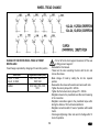
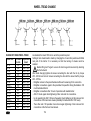
GEAR SHIFTING SCHEME
A - Standard tractor models
B - Tractor equipped with reversor
43
G150
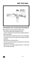
LEVER OF SHIFTING OF ROAD AND
REDUCED GEARS
H Road gears
N Neutral
L Reduced gears
Shifting is carried out with tractor in
standstill.
ACQUAINTANCE WITH TRACTOR
G154
G153
G153
PTO SELECTION CONTROL LEVER
a - Independent speed of PTO shaft
- PTO shaft speed depends upon
the engine speed
n - Neutral
b - Ground speed of PTO shaft
(through gearbox) - PTO shaft
speed depends upon the engaged gear speed
Shifting is made when the tractor stops.
Standard tractor models are equipped
with six-spline PTO shaft end.
∗ PTO SPEED CONTROL LEVER
a - 540 rpm
n - Neutral
b - 1000 (540E)rpm
Shifting is made when the tractor stops.
∗ Tractor can be equipped with the following changeable PTO shaft ends as
option:
six-spline PTO shaft end - 540 rpm
twenty-one-spline PTO shaft
end –
1000 rpm.
PTO speed shifting of either 540
or 1000 rpm is possible regardless to assembled PTO shaft end (with
six or twenty-one splines). PTO speed
and the shaft end type must be chosen
depending upon prescribed speed of implemented machine.
∗ PTO SPEED CONTROL LEVER TRACTOR EQUIPPED WITH
REVERSOR OR REDUCTOR FOR
CREEPING GEARS
a - 1000 (540E) rpm
n - Neutral
b - 540 rpm
Gear 540 E serves for reaching of
540 rpm of the PTO shaft with preservation of economical engine speed.
Shifting is made when the tractor stops.
44
ACQUAINTANCE WITH TRACTOR
C172
∗ REVERSOR SHIFTING LEVER
FForward drive; lever in forward
position
RBackward drive; lever in backward position
The reversor lever has no neutral
position. Therefore neutral must
be shifted by the main shifting
lever for stopping the tractor.
45
C173
PARKING BRAKE LEVER, PTO SHAFT
CONTROL LEVER AND PICK UP HITCH
CONTROL LEVER
1. Control lever of PTO shaft clutch
2. Parking brake lever
3. Pick up hitch control lever
ACQUAINTANCE WITH TRACTOR
H355
E157
SWITCHING ON THE FRONT OUTPUT
SHAFT ZUIDBERG
The front output shaft Zuidberg is
switched on with a switch on the
dashboard. Work of the switch is signalled by burning symbol on the switch.
The switch is equipped with a mechanical lock (1) against accidental switching
on. When switching on, press the lock
(1) in direction of the arrow.
When starting the engine, the
switch should be off.
BATTERY SWITCH
During long-time shutdown, repairs, failure or crash immediately
disconnect the battery by means
of the battery switch.
Battery switch is located on the left hand
tractor side in front of the cab.
FUEL TANK
The fuel tank is fitted at the right-hand
tractor side. A plastic 124- litre tank is installed as standard. At the customer’s
request a 150-litre tank may be installed.
Do not step on the fuel tank!
1 - battery connected
2 - battery disconnected
DRAINING PLUG OF FUEL TANK
Opening for draining of impurities is located in the bottom part of fuel tank.
46
OPERATION
Be familiar with shifting pattern
and test all positions of shifting
lever at stopped engine before
driving a new tractor.
Before driving, you must be sure
that at normal operation the
technical state of tractor corresponds to the safety traffic
condition before driving.
Page
Engine starting .......................................................................................................... 48
If engine does not start.............................................................................................. 49
Signalling of glow system failures ............................................................................. 49
Manipulation with motor starter ................................................................................. 49
Immediately after starting .......................................................................................... 50
Preheating of engine ................................................................................................. 50
∗Coolant heater......................................................................................................... 51
Starting the engine with using of coolant heater........................................................ 51
Setting in motion ....................................................................................................... 52
Selection of road or reduced speeds......................................................................... 53
Gear change ............................................................................................................. 53
Selection of drive direction - *reversal lever .............................................................. 53
Shifting from lower to higher gear speed................................................................... 54
Shifting from higher to lower gear speed................................................................... 54
Driving uphill.............................................................................................................. 55
Driving downhill ......................................................................................................... 55
Differential lock.......................................................................................................... 56
Control of front driving axle ....................................................................................... 56
Driving with front driving axle engaged ..................................................................... 56
Service brakes .......................................................................................................... 57
Air brakes of trailers and semi-trailers....................................................................... 57
Warning signal of air pressure drop .......................................................................... 57
Single and double hose brakes ................................................................................. 58
Single hose brakes.................................................................................................... 58
Double hose brakes .................................................................................................. 58
Trailer hydraulic brakes ............................................................................................. 59
Connection and disconnection of quick couplings of the trailer hydraulic brakes ...... 59
Stopping the tractor - parking brake .......................................................................... 60
Stopping the engine .................................................................................................. 60
Leaving the tractor .................................................................................................... 60
Warning signal of hydrostatic steering failure............................................................ 61
Important warnings.................................................................................................... 61
47
OPERATION
P11NG202a
P11NC203a
ENGINE STARTING
1. Insert the key into the key switch ("0"
position).
2. Depress the clutch pedal.
3. Move the main shifting lever into
neutral position.
4. Move the hand clutch lever into
braking position (safety interlock
switch will be actuated).
5. Turn the key from “0” position to "I"
position. The indication lamp of
glowing of thermo-start turns “ON“.
6. Wait until the indication lamp is off.
(The time is dependent on coolant
temperature).
In case that the indication lamp is
only flashing instead of lighting,
the
glowing
system
failed
(Chapter Signalling of glowing
system failures). Let repair the
indicated failure in a specialized
workshop.
7. Immediately after indication lamp
extinction (max. within 5 s) turn the
key from the position "I" into "II"
position (start).
8. Release the key immediately after
starting the engine, it returns
automatically into ”I” position. Do not
start longer than 15 sec.
48
OPERATION
G204
G205
G206
IF ENGINE DOES NOT START
Turn the key into position "0", wait 30
seconds and repeat starting.
Maximum 6 starting cycles are allowed
(15 seconds starting and 30 second
interruption make one cycle). Farther
starting of engine is allowed after cooling
of starter motor to the ambient
temperature.
Never help to the stopping engine
by the starter motor. There is
danger of damage of starter
motor.
SIGNALLING OF GLOW SYSTEM
FAILURES
Failure of glowing system is signalised by
flashing of the signalling lamp of glowing.
- If the signalling lamp of glowing is
flushing one times in one second at
stopped engine, glowing will take place
in emergency regime as at low
temperature regardless to coolant
temperature.
- If the signalling lamp of glowing is
flushing two times in one second at
stopped engine, glowing is put of
operation (out of function).
- If the signalling lamp of glowing is
flushing permanently at running
engine, failure of glowing regulator
occurred and glowing was not finished.
It is necessary to remove the failure
immediately, because there is danger
of battery discharging.
MANIPULATION WITH MOTOR
STARTER
It is forbidden to start the
tractor by short circuit of
starter motor connectors!
Start the tractor from the
driver’s seat only!
Disconnect the ground battery
pole, shift all levers into neutral
position, including PTO engagement, when any manipulation
with starter motor or repairing it!
Starter motor connectors are
covered with a cover.
49
OPERATION
G207
C208
IMMEDIATELY AFTER STARTING
After starting set the engine
speed to 800 up to 1000 min-1
and let the engine at idle running
for ca 2 minutes without load.
In that time check lubrication, charging
(indicator lights must be “off“) and other
functions assuring the correct engine
operation. Time of engine idle without
load must be kept especially in winter
season.
PREHEATING OF ENGINE
Continue with farther preheating the engine already while driving. Warming up
the engine by long idle run or fast increase of speed is dangerous for the
engine.
-1
Do not exceed engine speed above 2 000 min until the coolant temperature
reaches 45 °C.
50
OPERATION
C209
C210
∗COOLANT HEATER
Coolant heater is fitted at the right-hand
side of the engine block.
Output 1000 W
Voltage 220 V
STARTING THE ENGINE WITH USING OF COOLANT HEATER
Heater enables starting the engine at low ambient temperature by preheating the
coolant. The electrical installation and its protection against electrical shock hazard
must be done according to the valid regulations
1. Plug the heater first.
2. Plug the cable with connected heater to 220 V mains after.
With regard to reduction of engine wear when starting at low temperatures, producer
recommends to use the heater. Preheating time depends upon the ambient
temperature (1 to 2 hours before supposed starting are sufficient).
After finishing of heating, unplug the mains first and the heater only
after!
Electrical shock hazard!
It is necessary to ensure instruction of tractor operator’s and regular
revisions of the coolant heater including inlet cable accordingly with the
valid standard of the country, in which the tractor is operated, minimum
before each winter season.
51
OPERATION
C211
SETTING IN MOTION
1. Depress the clutch pedal.
2. Shift the main shifting lever into neutral.
3. Start the engine.
4. Set the engine speed to 800 r.p.m.
5. Select road or reduced gear.
6. ∗ Shift the reversor lever into the desired direction of tractor movement (forward
or reverse).
7. Shift the proper gear speed suitable for setting in motion.
8. Slightly increase engine speed.
9. Prepare the parking brake for releasing.
10. Release the clutch pedal up to point where the tractor starts to move and
simultaneously with engine speed increasing, continue with smooth releasing the
clutch.
11. Fully release the parking brake.
12. Accelerate smoothly and slowly.
52
Very fast acceleration can cause
overload of transmission, increased fuel consumption, excessive
tire wear and damage of
st
transported load. Use the 1 gear
for accelerating when driving with
heavy trailer uphill and in heavy
terrain only.
OPERATION
G150
SELECTION OF ROAD OR REDUCED
SPEEDS
H
road speeds
N
neutral
L
reduced speeds
When reduced speeds are used, gear
change is the same as in road speeds.
Considering low speed of the tractor,
change nearly always means moving off
from rest.
The change lever from road to
reduced speeds may be moved
only if the tractor is in rest.
C168b
E149a
GEAR CHANGE
Gears are changed using the main
change lever.
SELECTION OF DRIVE DIRECTION *REVERSAL LEVER
F - forward drive; the lever is in the front
position
R - backward drive; the lever is in the
back position
AStandard type of the tractor
Gears and drive direction are changed
using the change lever
BThe tractor is equipped with
reversal.
Gears are changed with the main
change lever, drive direction is changed
with the reversal lever.
53
Change is carried out when the tractor is
in rest.
OPERATION
C212
C213
SHIFTING FROM LOWER TO HIGHER
GEAR SPEED
Depress the clutch pedal (clutch
disengaged). In the same time loosen
the throttle pedal and shift the proper
higher gear speed. Fluently release the
clutch pedal (the clutch starts engaging)
and simultaneously increase engine
speed.
Note: For increasing of service life of
synchronizers, it is possible to apply socalled double clutching when shifting
from lower gears to higher gears.
SHIFTING FROM HIGHER TO LOWER
GEAR SPEED
Depress the clutch pedal and shift the
shifting lever through neutral position to
lower gear speed.
Note: For increasing of service life of
synchronizers, it is possible to apply socalled “between-gas” when shifting from
higher gears to lower gears.
54
OPERATION
C215
C216
DRIVING UPHILL
Shift from higher to lower speed
in time when going uphill, to
avoid engine speed dropping
below 800 min-1 and do not admit
driving leading to engine stopping
in consequence of overloading.
DRIVING DOWNHILL
Driving downhill without shifted
speed gear is forbidden. If driving
down a longer hill, shift so low
gear the sharper one the hill is. If
possible, shift the lower speed
gear still before driving downhill.
Note: The gear you use reliably for
driving uphill is safely suitable for driving
downhill.
55
OPERATION
C218
C219
G223
DIFFERENTIAL LOCK
Engaging is made by depressing of the
switch that will return in the original
position after releasing.
Engaging of the differential lock is
signalised with lighting symbol at the
switch.
When depressing the brake pedals, the
differential lock automatically disengages.
Engage the differential lock only
when the tractor is stoped.
Do not use the differential lock,
when turning.
CONTROL OF FRONT DRIVING AXLE
In basic position, the front driving axle is
engaged.
Engaging of the front driving axle is
signalized with lighting symbol at the
dashboard.
Disengaging is made with the switch that
is situated at the dashboard.
a - Front driving axle disengaged
b - Front driving axle engaged
At the stopped tractor, the front driving
axle is engaged at stopped tractor
(braked tractor, stopped engine, key
switch in “0” position).
At sudden drop of air pressure in
the tractor air pressure system,
the
front
driving
axle
is
automatically engaged.
DRIVING WITH FRONT DRIVING AXLE
ENGAGED
Use the front driving axle when
the rear wheels are slipping and
for increasing the traction force of
tractor.
Driving with engaged front diving
axle on the road and on hard
surface causes excessive wear of
front tires.
Permanent engagement of front driving
axle is permitted if an agriculture
machine or implement is attached in
front of the tractor. This condition is
specified in operator’s manual of each
particular machine.
Maximum permitted speed of the set with
such attachment is 15 km.h-1.
56
OPERATION
C221
C222
C223
SERVICE BRAKES
Disc brakes are of disc, wet,
hydraulically actuated, double pedal type
with automatic pressure compensator.
Both brake pedals must be
latched together when driving on
the road.
Use unlatched pedals for braking
right or left wheel separately
when working in terrain and fields
only.
Note: When driving downhill at steep
descent with a trailer or semi-trailer that
are equipped with air or hydraulic
brakes, it is necessary to brake with
service brake already from the beginning
of decline!
AIR BRAKES OF TRAILERS AND
SEMI-TRAILERS
Control of air brakes of trailers (semitrailers), is performed in such manner
that the brake effect of both vehicles is
synchronised.
When braking with one brake
pedal, the air brakes are not in
function!
At pressure drop, the relief valve
puts of operation secondary
appliances
(differential
lock,
disengaging of front driving axle,
front PTO shaft).
When driving with a hitched
trailer or semi-trailer, the service
brake pedals must be connected
together and secured with the
latch!
57
WARNING SIGNAL OF AIR
PRESSURE DROP
Decrease of air pressure under 450kPa
is indicated by a red lamp and red
symbol of a tractor with a sign STOP on
the dashboard.
Tractor with a braked trailer or
semi-trailer cannot continue in
driving when air pressure drops
under the critical margin 450 kPa,
until it comes to pressure
increase.
OPERATION
P11NX227
P11NX228
P11NX229
SINGLE AND DOUBLE HOSE
BRAKES
1. Coupling of single hose air brake
system.
2. Couplings of double hose air brake
system.
After disconnecting or without
any hitched trailer or semi-trailer,
it is necessary to cover the
couplings with caps.
SINGLE HOSE BRAKES
Operating pressure is adjusted with the
control valve at 600 ± 20 kPa.
Permitted speed of the tractor
with a hitched trailer (semi-trailer)
of maximum weight, approved for
the stated tractor model, is
maximum 30 km.h-1!
Maximum permitted speed of the
set is stated as the maximum
permitted speed of the slower
vehicle of this set.
DOUBLE HOSE BRAKES
Operating pressure is adjusted with the
control valve at 740 ± 20 kPa. Capacity
of air tank is 20 l. Left coupling cover is
marked with yellow color (braking
branch), right coupling cover is marked
with red color (filling branch).
Permitted speed of the tractor
with a hitched trailer (semi-trailer)
of maximum weight, approved for
the stated tractor model, is
-1
maximum 40 km.h !
Maximum permitted speed of the
set is stated as the maximum
permitted speed of the slower
vehicle of this set.
58
OPERATION
P11NE231
TRAILER HYDRAULIC BRAKES
Connect the trailer or semi-trailer hydraulic brakes with the quick coupler marked with
an arrow.
The control of the trailer (semi-trailer) hydraulic brakes and the control of the tractor
brakes ensure synchronized braking effect of both the vehicles. Working pressure is
enforced by oil supplied from the hydraulic gear-type pump that works permanently.
The trailer brake control valve is controlled by brake fluid pressure from the main
brake cylinders depending on force that influences the brake pedal. Upon maximum
pressing down the brake pedal, pressure on the coupling head should be 12 - 15
MPa. The trailer brake valve prefers the brake function to the hydraulic function.
In the event of shocks when you press down the brake pedal, you have to bleed the
hose from the brake valve to the quick coupling.
When driving with trailer, the brake pedals should be connected and safeguarded
with a lock!
When braking with one brake pedal, the trailer hydraulic brakes are out of
operation.
59
CONNECTION AND DISCONNECTION
OF QUICK COUPLINGS OF THE
TRAILER HYDRAULIC BRAKES
When connecting and disonnecting
the quick couplings you should be
aware of the rest of oil that is kept
in the quick coupling plug or
socket.
To protect environment you have
to remove the oil residues after
each disconnection of the quick
couplings with a textile rag.
OPERATION
G232
G233
C230
STOPPING THE TRACTOR - PARKING
BRAKE
At normal conditions stop the tractor
slowly. Shortly before stopping:
1. Depress the clutch pedal.
2. Move the main shifting lever into
neutral.
3. At each tractor stopping protect the
tractor against accidental movement
by setting of parking brake. Indicator
lamp located on the dash indicates
parking brake setting.
STOPPING THE ENGINE
The engine must be cooled after work
with fully loaded tractor.
1. Reduce engine speed to 800 - 1000
min-1 before stopping the engine and
let it run without load approximately
for 5 minutes.
2. Move the throttle control lever into
STOP position.
3. Pull up the control of engine stopping
(stopping device) and keep it in
pulled position until the engine stops
(push the control back).
4. After engine stopping is possible to
turn the switch key into “0“ position.
Note: At stopped engine the front driving
axle is automatically shifted into “on”
position.
LEAVING THE TRACTOR
Before leaving tractor with safety cab do
not forget to remove the key from the key
switch in “0” position (only at stopping
engine – the indicator of battery charging
lamp must be “on”) and lock the cab. at
cab tractors before leaving tractor. (The
key cannot be removed when it is in “I”
or “II” positions).
When the tractor stands on the hill,
wheels must also be locked with blocks.
The tractor must be properly
assured against accidental move:
60
1.
2.
3.
Engine must be “off”.
Speed gear 1 must be shifted.
Tractor must be braked with parking
brake.
When the tractor stands on the hill,
wheels must also be locked with blocks.
OPERATION
C231
G236
WARNING SIGNAL OF HYDROSTATIC
STEERING FAILURE
Failure of the hydrostatic steering pump
is after the pump signalised at the
dashboard with a corresponding symbol
at drop of oil pressure below 120 kPa.
Note: At starting of the tractor or at low
engine speed the signalling lamp can
blink and if then the signalling lamp, after
starting or increasing of speed, is “off”, it
does not represent a failure. The system
is in order.
IMPORTANT WARNINGS
In case that indicator of lubrication,
battery recharge or a fault of the
hydrostatic steering is on during normal
operation of the tractor, stop the tractor
immediately, stop the engine and contact
a specialised repair shop. This prevents
a serious damage or breakdown of the
tractor.
61
NOTE
62
RUNNING-IN THE TRACTOR
Page
General principles for running-in a new tractor in the course of first 100 operating
hours ......................................................................................................................... 64
In the course of first 100 operating hours .................................................................. 64
From 100 operating hours ......................................................................................... 65
63
RUNNING-IN THE TRACTOR
G251
GENERAL PRINCIPLES FOR RUNNING-IN A NEW TRACTOR IN THE COURSE
OF FIRST 100 OPERATING HOURS
In the course of first 100 operating hours:
- do not load the engine excessively;
- avoid run with partial load of the engine;
- avoid excessive idle run time;
- check frequently level of oil in the engine (increased consumption of oil within
this period is normal);
- checks screwed joints, in particular supporting parts of the tractor;
- remedy immediately all found faults; this prevents consequent damages and/or
threats to safety of operation;
- follow also the same procedure after overhaul of the tractor
64
G252
IN THE COURSE OF FIRST 100
OPERATING HOURS
- perform running-in in normal traffic;
- retighten nuts of front and rear wheels
including connection flange/rim by the
prescribed torques.
RUNNING-IN THE TRACTOR
E256
FROM 100 OPERATING HOURS
After running-in you can work with the
tractor without any limitation.
Operating values of engines of tractors:
Recommended oper1400-2300 min-1
ating speed
Idle run
800±25 min-1
Operating oil pres0.2-0.5 MPa
sure
Oil pressure at idle
min. 0.05 MPa
run
Max. temperature of
106 °C
cooling fluid
65
NOTE
66
TRANSPORT USE
Page
Front hook ................................................................................................................. 68
Multi-level quick-adjustable hitch CBM...................................................................... 68
Height adjustment and dismounting of the multi-level hitch CBM.............................. 68
Automatic hitch of the multi-level hitch device CBM.................................................. 69
Modular system of hitches for trailers and semi-trailers ............................................ 69
Bracket Module of pivoted pull bar ............................................................................ 69
Pivoted pull bar ......................................................................................................... 69
Bracket Module of pivoted pull bar with fixed pin ...................................................... 70
Bracket module with ball ø 80 ................................................................................... 70
∗Towing bar............................................................................................................... 70
Coupling of a single-axle trailer ................................................................................. 71
Uncoupling of a single-axle trailer ............................................................................. 71
Hitch CBM for single-axle trailers .............................................................................. 71
Coupling with a trailer or semi-trailer ......................................................................... 72
Hook of the mounting for a single-axle trailer ............................................................ 72
Maximum permitted vertical static loading of hitches for trailers and semi-trailers .... 73
Before a drive make sure that the
technical condition ensures safe
operation of the tractor.
In case that a trailer or implement is
coupled, verify its coupling and proper
fixing of the load. Never get out of the
tractor to couple a trailer yourself. Pay
also attention to your assistant.
67
TRANSPORT USE
E301
E302
E303
FRONT HOOK
It can only be used for towing of the tractor without trailer or other accessories attached.
Use a towing bar or rope to extricate the tractor.
Never use chains! Risk of a lethal injury
with rupture of the chain!
It is forbidden to use axles of the tractor
(individual travel wheels) as a winch with
extrication of the stuck tractor.
MULTI-LEVEL QUICK-ADJUSTABLE
HITCH CBM
It is used for coupling of double-axle of
light single-axle trailers. The guide hitch
is height-adjustable. When working with
farming mechanisms it is necessary to
adjust height of the hitch or dismount it.
HEIGHT ADJUSTMENT AND
DISMOUNTING OF THE MULTI-LEVEL
HITCH CBM
Moving of the control lever in direction of
the arrow to position (1) unlocks the
lever, consequent moving to position (2)
engages the arrestment pins (3); this releases the multi-level hitch and its height
can be adjusted or the hitch can be dismounted. After release of the lever from
position (2) the arrestment pins (3) are
disengaged and the lever returns automatically to its initial position.
68
TRANSPORT USE
E304
E305
E306
AUTOMATIC HITCH OF THE MULTILEVEL HITCH DEVICE CBM
Moving of the lever (1) in direction of the
arrow (a) slides the pin (2) into the upper
position that is indicated by the extracted
warning indicator (3), see fig. (A).
After sliding the hitch onto the pole eye
the pin slides automatically into the
trailer pole eye. The hitch pin (2) can be
engaged manually by sliding the lever (1)
in direction of the arrow (b). Engagement
of the pin is indicated by the retracted
warning indicator (3), see fig. (B).
After connecting the trailer it is
always necessary to check
whether the warning indicator (3)
is retracted as shown on fig. (B).
MODULAR SYSTEM OF HITCHES FOR
TRAILERS AND SEMI-TRAILERS
Types of modules:
Fig. (B) – Pivoted pull bar bracket.
Fig. (C) – Pivoted pull bar bracket with
fixed pin.
Fig. (D) – Bracket with ball ø 80.
Dismounting – fig. (A):
1. Dismount the locking screw (1).
2. Secure the module against fall,
unlock and dismount the pins (2).
3. Slide out the module from the bracket
downward.
BRACKET MODULE OF PIVOTED
PULL BAR
The bracket module of the pivoted pull
bar is located in the multi-level hitch
bracket.
Mounting is performed in reverse order.
69
PIVOTED PULL BAR
Dismounting:
1. Unlock and dismount the pins (1).
2. Pull out the pivoted pull bar in direction of the arrow.
Mounting is performed in reverse order.
TRANSPORT USE
E307
E308
E312
BRACKET MODULE OF PIVOTED
PULL BAR WITH FIXED PIN
Mounting and dismounting of the pivoted
pull bar should be performed as described in the chapter “Pivoted pull bar”.
Coupling the pole eye to the fixed pin (3):
1. Unlock and dismount the pin (1).
2. Lift the locking wedge (2) in direction
of the arrow.
3. Couple the pole eye to the fixed pin
(3).
4. Return the locking wedge (2) to its
initial position and lock it using the
pin (1).
BRACKET MODULE WITH BALL Ø 80
The bracket with ø 80 is used
only for coupling of trailers with a
coupling device designed for
balls ø 80.
∗TOWING BAR
Height of the towing bar can be adjusted
within entire extent of the adjustable
height. Only those farming mechanisms
can be attached to the towing bar that
load it permanently downwards.
When working with the towing bar
dismount the multi-level hitch and
pivoted pull bar.
Fig. (A) – Unlocking of the hitch:
Moving of the lever (1) in direction of the
arrow slides off the locking wedge (2).
Fig. (B) – Locking of the hitch. (B):
Moving of the lever (1) in direction of the
arrow slides in the locking wedge (2).
70
TRANSPORT USE
P+11N003
E311
E309
COUPLING OF A SINGLE-AXLE
TRAILER
Coupling can be performed using the
hydraulic circuit lever (2). The hitch hook
with the trailer pole eye is lifted hydraulically to the position where the supporting
hooks click under pins of the hitch carrier. The lifting arms of the hydraulic device then shall be lowered to lock the
supporting hooks onto the carrier pins;
the telescopic pull rods shall not be under any tension.
UNCOUPLING OF A SINGLE-AXLE
TRAILER
This can be performed after slight lifting
of the hitch by the inner hydraulic circuit
lever. Move the control lever backwards.
The lever is located on the left side of the
driver’s seat. Lower the hitch using the
inner hydraulic circuit lever and disconnect the trailer pole eye.
HITCH CBM FOR SINGLE-AXLE
TRAILERS
The hitch for a single-axle trailer can be
equipped with a hook (A) that is designed for coupling of single-axle trailers
having poles according to the standard
ISO 5692 (inner diameter of the eye
50mm and height of the eye 30mm) or
pivoted pull bar (B).
The coupling hook is lowered and lifted
hydraulically using length-adjustable
telescopic pull rods.
Replacement of the hook for the pivoted
pull bar (C):
1. Lower the hitch.
2. Unlock and remove the pin (1).
3. Remove the hook in direction of the
arrow.
The pivoted pull bar is mounted in reverse order.
71
TRANSPORT USE
G313
G900
COUPLING WITH A TRAILER OR
SEMI-TRAILER
The tractor can be coupled only with a
tractor trailer after matching of operating
brakes of the tractor and pneumatic or
hydraulic brakes of the trailer. In case of
coupling with a semi-trailer the static
loading of the rear axle of the tractor may
not exceed the maximum permitted value.
HOOK OF THE MOUNTING FOR A
SINGLE-AXLE TRAILER
The hook of the mounting for a singleaxle trailer is located in the bracket on
the left-hand side of the cabin back wall.
72
TRANSPORT USE
MAXIMUM PERMITTED VERTICAL STATIC LOADING OF HITCHES FOR TRAILERS AND SEMITRAILERS
Hitch type
Permitted
vertical
static
loading
Diameter
of hitch
pin
2,000kg
31mm
Hitch type
Hitch class D2
Permitted
vertical
static
loading
Diameter
of hitch
pin
2,000kg
38mm
1,500 kg
28mm
Hitch class C
2,000 kg
43mm
Maximum weight of a coupled braked trailer or semi-trailer shall not exceed the value given on
the type plate of the tractor and value given in the MOT certificate of the vehicle. Hitch of class C:
max. weight of the trailer 6,000kg. Hitch of class D2: max. weight of the trailer 14,000kg.
73
TRANSPORT USE
MAXIMUM PERMITTED VERTICAL STATIC LOADING OF HITCHES FOR TRAILERS AND SEMI-TRAILERS
Hitch type
Permitted
vertical
static
loading
Diameter
of the pin
(ball) of
the hitch
31mm
3,000kg
80mm
47mm
1,200kg
32mm
Permitted
vertical
static
loading
Diameter
of the pin
(ball) of
the hitch
736kg
3,000kg
Hitch type
Hitch type
Permitted Diameter
vertical
of the pin
static
(ball) of
loading
the hitch
fixed pin
2,000kg
44.5mm
Maximum weight of a coupled braked trailer or semi-trailer shall not exceed the value given on the type plate of the tractor
and value given in the MOT certificate of the vehicle. Maximum speed of the vehicle train is given by the maximum permitted speed of the slower vehicle of the vehicle train.
74
PTO DRIVE OF AGRICULTURAL MACHINES
Page
Operation with PTO................................................................................................... 76
Hand control lever of PTO shaft clutch...................................................................... 76
∗Hand control lever of PTO shaft clutch with pneumatic control ............................... 77
Changable pto end pieces ........................................................................................ 77
Change of depending and independent rotations...................................................... 78
∗ PTO speed control lever......................................................................................... 78
∗ PTO speed control lever - Tractor equipped with reversor or reductor for
creeping gears .......................................................................................................... 78
Front output shaft Zuidberg ....................................................................................... 79
Engagement of the front output shaft Zuidberg ......................................................... 79
Maximum transferred power...................................................................................... 79
Drive of machines with greater inertial masses ......................................................... 80
Before attaching of an implement,
driven by means of the tractor
PTO shaft, check the speed
compatibility of both, it means
tractor PTO shaft and implement
driven shaft (540 r.p.m. or 1000
r.p.m.). Different PTO speed
values may cause serious
damages and injuries.
75
PTO DRIVE OF AGRICULTURAL MACHINES
E352b
C352
OPERATION WITH PTO
1. When working with the output shaft pay attention to proper fixing of all
covers.
2. After completion of work install always the output shaft cover.
3. Connect and disconnect the articulated shaft of the coupled mechanism
to the rear output shaft of the tractor always when the engine is stopped,
output shaft disengaged and lever of shifting of dependent and
independent rpm of the output shaft in position N - neutral!
4. Connect and disconnect the articulated shaft of the coupled mechanism
to the front output shaft of the tractor always when the engine is stopped
and output shaft disengaged!
5. Perform any repairs or cleaning of parts of the coupled mechanisms
driven by the output shaft only when the engine is stopped, output shaft
disengaged and lever of shifting of dependent and independent rpm of
the output shaft in position N - neutral.
C350
HAND CONTROL LEVER OF PTO
SHAFT CLUTCH
With rising of the hand control lever of
the PTO clutch into the upper position it
comes to disengaging of the PTO clutch.
The upper position of lever is indicated
with indicator light located in the
dashboard. The lever is automatically
locked in the upper position with a latch.
Releasing of locking and return of the
lever into the lower position is possible
after rising the lever and depressing the
push-button at the front of the lever.
76
Upper position
Lower position
- clutch is disengaged
- clutch is engaged
PTO DRIVE OF AGRICULTURAL MACHINES
C353
E357
∗HAND CONTROL LEVER OF PTO
SHAFT CLUTCH WITH PNEUMATIC
CONTROL
∗As option, the tractor can be equipped
with disengaging of the PTO clutch with
pneumatic control. The function of the
hand control lever of the PTO clutch is
same as standard tractor model. At air
pressure of min. 500 kPa, it is possible,
by depressing of the clutch pedal, to
disengage the PTO clutch simultaneously with the travel clutch.
CHANGABLE PTO END PIECES
If equipped with reversation or creeper,
the tractor can be equipped with 6-spline
or 21-spline PTO end piece on request.
Changing the end piece:
1. Use circlip pliers to remove the
circlip (1).
2. Remove the end piece by pulling it
in the direction shown by the arrow
(2).
3. Procede contrariwise to place the
end piece, take proper care while
placing the circlip (1).
77
PTO DRIVE OF AGRICULTURAL MACHINES
G154
G153
G153
CHANGE OF DEPENDING AND
INDEPENDENT ROTATIONS
Change is implemented when the tractor
is in rest and the hand lever switching off
the output shaft coupling is off.
aoutput
shaft
independent
rotations (number of rotations
depends on number of the engine
rotations)
nneutral position. Use it to make
easier connection of the cardan
shaft of an agricultural machine.
The end piece of the rear output
shaft may rotate freely.
boutput shaft depending rotations
(number and direction of the
rotations depend on the gear and
position of the reversal lever).
∗ PTO SPEED CONTROL LEVER
a - 540 rpm-1
n - neutral
b - 1000 (540E) rpm-1
The tractor standard type is equipped
-1
only with 540 rpm and the lever is not
installed.
Change is implemented when the tractor
is in rest and the hand lever switching off
the output shaft coupling is off.
∗ PTO SPEED CONTROL LEVER TRACTOR EQUIPPED WITH
REVERSOR OR REDUCTOR FOR
CREEPING GEARS
a - 1000 (540E) rpm-1
n - neutral
b - 540 rpm-1
The tractor standard type is equipped
only with 540 rpm-1 and the lever is not
installed.
Change is implemented when the tractor
is in rest and the hand lever switching off
the output shaft coupling is off.
78
PTO DRIVE OF AGRICULTURAL MACHINES
E356
H355
FRONT OUTPUT SHAFT ZUIDBERG
The front output shaft is equipped with a
fixed 6- or 21-spline terminal and its
speed is 1,000 rpm only.
The tractor may be equipped with an
optional front output shaft with both
directions of rotation:
a - in direction of rotation of the
engine (standard)
b - against direction of rotation of the
engine (∗optional)
ENGAGEMENT OF THE FRONT
OUTPUT SHAFT ZUIDBERG
The front output shaft Zuidberg can be
engaged and disengaged using a switch
on the dashboard. Activation of the
switch is indicated by the illuminated
symbol on the switch.
The switch is fitted with a mechanical
lock (1) against unintentional switching
on. When activating the switch, depress
also the lock (1) in direction of the arrow.
The switch shall be off when
starting the engine.
79
E358
MAXIMUM TRANSFERRED POWER
Output shaft
Transferred
power
front (Zuidberg)
1,000 rpm
45kW*
rear
1,000 rpm
full engine power
540 rpm
full engine power
540E rpm
full engine power
*In case of a transfer of power without
shocks, the value of the transferred
power may be increased to 50kW.
PTO DRIVE OF AGRICULTURAL MACHINES
DRIVE OF MACHINES WITH
GREATER INERTIAL MASSES
(CRUSHERS, ROTARY HARROW,
REAPERS, ETC.)
The propeller shaft for drive of such
machines shall be equipped with a socalled free engine clutch that provides
disconnection of the transfer of torques
with backward effects from the machine
to the tractor.
80
HYDRAULIC SYSTEM
Page
Hydraulic system....................................................................................................... 82
Hydraulics control panel ............................................................................................ 83
Ways to regulate inner hydraulic circuit..................................................................... 83
Controlling the inner hydraulic circuit ........................................................................ 84
Free (floating) position .............................................................................................. 84
Adjustable stop.......................................................................................................... 84
Three-point hitch Lowering speed control ................................................................. 85
Hydraulic system sensitivity control........................................................................... 85
Position regulation of the lifting of the rear three-point hitch ..................................... 86
Power regulation of the lifting of the rear three-point hitch ........................................ 87
Mixed regulation of lifting the rear three-point hitch................................................... 88
Exterior rear hydraulic arms controls......................................................................... 89
Outer hydraulic circuit ............................................................................................... 89
Outer hydraulic circuit controls .................................................................................. 90
Locking control levers ............................................................................................... 91
Different functions of outer hydraulic circuit control levers ........................................ 92
Different functions of outer hydraulic circuit control levers ........................................ 93
Different functions of outer hydraulic circuit control levers ........................................ 94
Different functions of outer hydraulic circuit control levers- one section distributor ... 95
Amount of oil taken from outer hydraulic drives ........................................................ 96
Quick couplers with dripping oil reservoir .................................................................. 97
Connecting and disconnecting quick couplers .......................................................... 97
Connecting machinery and tools to outer hydraulic circuit ........................................ 98
Connecting machinery and tools assembled from more parts................................... 98
The hydraulic system is intended for
lifting and lowering of agricultural machines and implements attached in the
rear three point hitch.
81
HYDRAULIC SYSTEM
P11N001
HYDRAULIC SYSTEM
It consists of the inner and outer circuits.
Gear pump is the source of pressure oil.
Oil is taken from reservoir shared by
gearbox and transmission.
Hydraulic pump cannot be switched off.
If the engine is working, the pump is on.
The amount supplied is 50 liters per
minute.
The pressure in hydraulic system raised
by the hydraulic pump is restricted by a
safety valve to 19 MPa.
82
HYDRAULIC SYSTEM
P+11N001
P+11N002
HYDRAULICS CONTROL PANEL
Hydraulics control panel is located in the
area of the right wing.
Controlling the rear three-point hitch is
enabled by the inner hydraulic circuit (1).
Controlling outer hydraulic circuits
(couplers) is enabled by outer hydraulic
circuit (2).
WAYS TO REGULATE INNER HYDRAULIC CIRCUIT
Hydraulic system allows of three ways to regulate the lifting of the rear three-point
hitch:
Position regulation (img. 1) – the tool connected to the rear three-point hitch is
automatically kept in the same height (position) with regard to the tractor.
Mixed regulation (img. 2) – a combination of position and power regulation. Suitable
mainly for tilling areas of different soil resistance.
Power regulation (img. 3) – the tool connected to the three-point hitch is
automatically being adjusted depending on changing soil resistance.
All the regulations can also be used when working with a tool equipped with a
support wheel in so-called free (floating) position.
83
HYDRAULIC SYSTEM
P+11N003
P+11N004
P+11N009
CONTROLLING THE INNER
HYDRAULIC CIRCUIT
1. position or power regulation lever
2. lever for selecting floating position,
adjusting the height of the threepoint hitch in position regulation or
mixed regulation.
3. three-point hitch lowering speed
control
4. hydraulic system sensitivity control
5. adjustable stop
FREE (FLOATING) POSITION
Free (floating) position makes it possible
to work with tools with a support wheel.
In this position, the arms of the rear
three-point hitch are loose.
Move lever (2) to the front position (a).
The position of lever (1) makes no
difference.
ADJUSTABLE STOP
Under
default
settings,
it
is
recommended to set the adjustable stop
(1) to a position on the edge between
floating position and the beginning of the
range of lifting of the rear three-point
hitch (b). After pushing the lever towards
you, the lever can be moved over the
adjustable stop.
84
HYDRAULIC SYSTEM
P+11N006
E408
THREE-POINT HITCH LOWERING
SPEED CONTROL
Three-point hitch lowering speed control
(3) selects the speed of lowering the
arms of the rear three-point hitch.
Turning the knob in (b) direction reduces
the lowering speed of the arms of the
rear three-point hitch, turning it in (a)
direction increases the speed. If the knob
is turned in (b) direction to its stop point,
the arms of the rear three-point hitch
cannot be lowered.
HYDRAULIC SYSTEM SENSITIVITY
CONTROL
Hydraulic system sensitivity control (4)
adjusts the sensitivity of the hydraulics in
power or mixed regulation. Turning the
knob in (a) direction increases sensitivity,
turning it in (b) direction decreases
sensitivity.
85
HYDRAULIC SYSTEM
P+11N008
POSITION REGULATION OF THE LIFTING OF THE REAR THREE-POINT HITCH
Position regulation of the lifting of the rear three-point hitch means that the tool connected to the rear three-point hitch is
automatically kept in the same height (position) with regard to the tractor.
Move lever (1) to the front position (d). Adjust the height of the rear three-point hitch with tools within the (b) range by lever (2).
Adjusting the height is smooth within the range 1-9. In position 1, the arms of the rear three-point hitch are in the lower position, in
position 9, in the highest position. Position (c) is a transport position when the tools connected to the rear three-point hitch is
raised at maximum.
To transport tools which are connected to the rear three-point hitch always use position regulation.
To raise tools into transport position, turn the three-point hitch lowering speed control knob (3) in the direction shown by
the arrow up to the stop point, which results in interrupting the oil flow in hydraulics. Should tools connected to the rear
three-point hitch not be lowered, check the position of the speed lowering control knob (3) – turn it in the opposite
direction than shown by the arrow.
If tools connected to the rear three-point hitch are long and heavy, the arms of the rear three-point hitch may get locked in
the transport position during transport. If the lowering speed control knob (3) is loosened and the tools still cannot be
lowered, move lever (2) to the floating position (c) for a short time and immediately get back to the lowering range (d). The
arms of the rear three-point hitch start to go down as set by lever (2).
86
HYDRAULIC SYSTEM
P+11N010
POWER REGULATION OF THE LIFTING OF THE REAR THREE-POINT HITCH
Power regulation of the lifting of the rear three-point hitch means that the tool connected to the rear three-point hitch is
automatically being adjusted depending on changing soil resistance.
Set the adjustable stop (5) to a position on the edge between floating position and the beginning of the range of lifting of the rear
three-point hitch.
Move lever (2) to (f) position – to the adjustable stop (5).
Move lever (1) to (g) position, accelerate the tractor and move lever (1) in the direction shown by the arrow to set the depth of
tilling (in (g) position, depth is the lowest).
Once the depth of tilling is set, lever (1) must be kept in constant position. At the end of each row, raise the tool connected to the
rear three-point hitch only by moving lever (2) to (e) position. To lower the tool to its operating position again, move lever (2) to (f)
position.
The rear three-point hitch may start oscillating under the influence of changing soil resistance. To reduce oscillation, set
lower hydraulic system sensitivity by turning the control knob (4) in (b) direction.
87
HYDRAULIC SYSTEM
P+11N011
MIXED REGULATION OF LIFTING THE REAR THREE-POINT HITCH
Mixed regulation of lifting the rear three-point hitch means that the tool connected to the rear three-point hitch is automatically
being adjusted depending on changing soil resistance and at the same time it prevents any increase in depth of tilling in case of
smaller soil resistance.
Set the depth of tilling by lever (1) as described in “Power regulation of the lifting of the rear three-point hitch“. Then start moving
lever (2) in the direction shown by the arrow until the arms of the rear three-point hitch start to rise slightly. Herewith, mixed
regulation has been set. Move the adjustable stop (5) to lever (2) which has been set and lock it. At the end of each row, raise the
tool connected to the rear three-point hitch only by moving lever (2) to (e) position. To lower the tool to its operating position
again, move lever (2) to the preset stop.
88
HYDRAULIC SYSTEM
P+11N016
P+11N012
EXTERIOR REAR HYDRAULIC ARMS CONTROLS
Exterior rear hydraulic arms controls are located on the rear right wing. They make it
easier for the operator to conncet tools by controlling the movements of the lower
drawbars of the three-point hitch from the outside. They only serve for connceting
and disconnecting the tools.
Img. (A)
Before using exterior controls, move the power regulation lever (1) to its utmost
position.
Lowering hydraulic arms img. (B):
Move lever (3) in the direction shown by the arrows (moving the lever is restricted
with a link). By repeating this procedure, hydraulic arms are lowered in small steps.
Raising hydraulic arms img. (C):
Move lever (3) in the direction shown by the arrows (moving the lever is restricted
with a link). By repeating this procedure, hydraulic arms are raised in small steps.
If the lifting device controlled by exterior controls is loaded, movement of the
lower drawbars within one step (on the exterior controls) is longer than if
unloaded.
OUTER HYDRAULIC CIRCUIT
It supplies pressure oil for hydraulic
devices on outer drives of hydraulics
ended with couplers. Coupler sockets
with 12.5 mm bore are in accordance
with the international recommendation of
ISO.
89
HYDRAULIC SYSTEM
P+11N015
OUTER HYDRAULIC CIRCUIT CONTROLS
Outer hydraulic circuit controls are located on the right wing.
lever (a) controls the lower section of distributor – quick couplers (1) and (2)
lever (b) controls the central section of distributor – quick couplers (3) and (4)
lever (c) controls the upper section of distributor – quick couplers (5) and (6)
Quick coupler (0) is directly connected with transmission and it is supposed for recuperative oil of exterior hydraulic appliances
(e.g. from rotary hydraulic engines etc.).
According to the equipment of the tractor, the following combinations of control levers and quick couplers can be supplied:
lever (a) – quick couplers (1) and (2)
levers (a) and (b) – quick couplers (1), (2), (3) and (4)
levers (a),(b) and (c) – quick couplers (1), (2), (3), (4), (5) and (6)
Quick coupler (0) is supplied in any case.
If the tractor is equipped with front three-point hitch, use lever (b) to control it. When the front three-point hitch is used,
quick couplers cannot be connected as they are pressured together with the front three-point hitch! When you finish using
the front three-point hitch and want to use the section with quick couplers 3 and 4 with connection to the front three-point
hitch, raise the arms of the front three-point hitch to the transport position and move the front three-point hitch lever to the
„locked“ position.
90
HYDRAULIC SYSTEM
P+11N014
LOCKING CONTROL LEVERS
Outer hydraulic circuit control levers are
locked in neutral (N) position.
To unlock them, raise the lock control (1)
and turn it to a stop point in the direction
shown by the arrow.
To lock them again, move the levers to
neutral (N) position and turn the lock
control in the opposite direction than
shown by the arrow to a stop point and
push the control down. This locks the
lever in neutral position.
For safety reasons, always lock
outer hydraulic circuit levers in
neutral position (N).
91
HYDRAULIC SYSTEM
P+11N017
DIFFERENT FUNCTIONS OF OUTER HYDRAULIC CIRCUIT CONTROL LEVERS
There are four positions of the lever (a):
N - Neutral position. Quick coupler drives (1) and (2) are closed and oil in the hydraulic appliance connected is blocked. Lever
(a) is locked in this position.
1 - Pressure in quick coupler (1). Quick coupler (2) is connected with the drain. Lever (a) is locked in this position. In case
pressure exceeds 16.5 MPa when connected to quick coupler (1), lever (a) automatically returns to (N) position – „kick-out“
function.
2 - Pressure in quick coupler (2). Quick coupler (1) is connected with the drain. Lever (a) is locked in this position. In case
pressure exceeds 16.5 MPa when connected to quick coupler (2), lever (a) automatically returns to (N) position – „kick-out“
function.
P - Floating position. Both quick couplers (1) and (2) are connected with the drain and oil is free to flow in both directions.
Lever (a) is locked in this position.
92
HYDRAULIC SYSTEM
P+11N018
DIFFERENT FUNCTIONS OF OUTER HYDRAULIC CIRCUIT CONTROL LEVERS
There are four positions of the lever (b):
N - Neutral position. Quick coupler drives (3) and (4) are closed and oil in the hydraulic appliance connected is blocked. Lever
(b) is locked in this position.
3 - Pressure in quick coupler (3). Quick coupler (4) is connected with the drain. It is necessary to hold lever (b) in this position,
when released, lever (b) automatically returns to (N) position. In addition, quick coupler (3) is equipped with a one-way
valve – convenient for connecting a tool which requires higher degree of impermeability – minimum lowering of the tool
during transport.
4 - Pressure in quick coupler (4). Quick coupler (3) is connected with the drain. Lever (b) is locked in this position.
P - Floating position. Both quick couplers (3) and (4) are connected with the drain and oil is free to flow in both directions.
Lever (b) is locked in this position.
93
HYDRAULIC SYSTEM
P+11N019
DIFFERENT FUNCTIONS OF OUTER HYDRAULIC CIRCUIT CONTROL LEVERS
There are four positions of the lever (b) which controls quick couplers (5) and (6):
N5-
6P-
Neutral position. Quick coupler drives (5) and (6) are closed and oil in the hydraulic appliance connected is blocked. Lever
(c) is locked in this position.
Pressure in quick coupler (5). Quick coupler (6) is connected with the drain. It is necessary to hold lever (c) in this position,
when released, lever (c) automatically returns to (N) position. In addition, quick coupler (5) is equipped with a one-way
valve – convenient for connecting a tool which requires higher degree of impermeability – minimum lowering of the tool
during transport.
Pressure in quick coupler (6). Quick coupler (5) is connected with the drain. Lever (c) is locked in this position.
Floating position. Both quick couplers (5) and (6) are connected with the drain and oil is free to flow in both directions.
Lever (c) is locked in this position.
94
HYDRAULIC SYSTEM
P+11N017d
DIFFERENT FUNCTIONS OF OUTER HYDRAULIC CIRCUIT CONTROL LEVERS- ONE SECTION DISTRIBUTOR
There are four positions of the lever (a):
N - Neutral position. Quick coupler drives (1) and (2) are closed and oil in the hydraulic appliance connected is blocked. Lever
(a) is locked in this position.
1 - Pressure in quick coupler (1). Quick coupler (2) is connected with the drain.
2 - Pressure in quick coupler (2). Quick coupler (1) is connected with the drain. Lever (a) is locked in this position.
P - Floating position. Both quick couplers (1) and (2) are connected with the drain and oil is free to flow in both directions.
Lever (a) is locked in this position.
95
HYDRAULIC SYSTEM
Working area: in flat terrain
Max. amount of oil taken: 20 liters
Gearbox filling: standard filling
Working area: in a slope
Max. amount of oil taken : 13 liters
Gearbox filling : standard filling
Working area : in flat terrain
Max. amount of oil taken : 27 liters
Gearbox filling :
gearbox oil filling increased by 7 liters
(max. amount of oil in gearbox allowed)
E413
AMOUNT OF OIL TAKEN FROM
OUTER HYDRAULIC DRIVES
For maximum amount of oil taken see
the following table.
Working area : in a slope
Max. amount of oil taken : 20 liters
Gearbox filling :
gearbox oil filling increased by 7 liters
(max. amount of oil in gearbox allowed)
If the amount taken exceeds the
limit, hydraulic pump can absorb
air and can get damaged.
If the amount of oil in transmission
decreases after disconnecting the tool
due to its permanent outflow out of the
tractor into the machine’s hydraulic
circuit, refill the oil missing.
96
HYDRAULIC SYSTEM
P+11N020
*QUICK COUPLERS WITH DRIPPING
OIL RESERVOIR
On request, dripping system for holding
leakage oil can be installed. Check the
reservoir regularly; if it is full, empty it
ecologically.
CONNECTING AND DISCONNECTING
QUICK COUPLERS
When connecting or disconnecting
quick couplers, be careful about
leakage oil which rests on the
coupler socket.
To behave ecologically, remove the
leakage oil each time after
disconnecting the couplers with a
textile cloth.
97
HYDRAULIC SYSTEM
CONNECTING MACHINERY AND TOOLS TO OUTER HYDRAULIC CIRCUIT
Connecting a double acting cylinder
A double acting cylinder must always be connected to quick couplers of one section.
Connecting machinery and tools assembled from more parts
When working with agriculture machinery which is assembled from more parts (combinators, scrubbers, or harrows) where the
edge frame is hinged to the central frame because it is diagonally folded during transport by independent hydraulic cylinders
which are controlled by outer hydraulic circuit of the tractor, it is recommended to connect the lifting arms of the cylinders to quick
couplers (3) and (5) which are equipped with a one-way valve.
Connecting rotary hydraulic engine
If a hydraulic engine is connected to outer hydraulic drive, it is always necessary to connect its returnable arm to quick coupler
(0). Filling (pressure) arm can be connected to quick couplers (1) or (2), where the hydraulic engine is protected by the “kick-out”
function from overload. This function stops the hydraulic engine if pressure in the filling arm exceeds 17 MPa.
Connecting reverse rotary hydraulic engine
Due to its function, reverse rotary hydraulic engine must be connected to quick couplers of one section. It is recommended to use
quick couplers (1) and (2), where the hydraulic engine is protected by the “kick-out” function from overload. This function stops
the hydraulic engine if pressure in the filling arm exceeds 17 MPa. If the hydraulic engine is connected to quick couplers of
different sections, both arms must be equipped with safety valves which can be relied on to restrict high pressure peaks during
run-out. Connect the safety valves drain to quick coupler (0).
Connecting external hydraulic distributor
It is recommend to connect external hydraulic distributor to quick couplers (4) or (6). Control levers (b) and (c) are mechanically
locked in these positions without hydraulic lock.
Connectable machinery which makes use of oil in outer hydraulic circuit must be filled with the same kind of oil
as recommended for tractor gearbox!
Quick coupler sockets of connectable machinery must be cleaned properly before connecting.
98
HITCHES
Page
Rear three-point hitch.............................................................................................. 100
Safety principles with work with a three-point hitch ................................................. 100
Height adjustment of lifting pull rods ....................................................................... 101
Fixed and free position of lower hydraulic pull rods................................................. 101
Limiting pull rods ..................................................................................................... 101
Upper pull rod.......................................................................................................... 102
Selection of holes in the bracket ............................................................................. 102
∗Lower pull bars with extensible terminals .............................................................. 103
∗Lower pull bars with hooks CBM ........................................................................... 103
Blocking of lower linkages with cbm hooks ............................................................. 103
∗Front three-point hitch ........................................................................................... 104
Adjustment of lifting speed of the front three-point hitch ......................................... 104
Controlling front three-point hitch ............................................................................ 105
Hydraulic locking of the front three-point hitch ........................................................ 106
Working and transport positions of the front three-point hitch ................................. 106
Drive with farming mechanisms attached to the front three-point hitch ................... 106
99
HITCHES
REAR THREE-POINT HITCH
It is designed for coupling of carried or
semi-carried farming mechanisms and
implements with hitch points of category
I or II according to ISO.
The categories differ in the length of the
hitch axis, i.e. distance of centres of balls
of lower hitch joints with attached implements.
Category I.
Length of hitch axis
∅ of holes of coupling balls
of lower pull rods acc. to ISO
∅ of the upper pull rod hole
Category II.
Length of hitch axis
∅ of holes of coupling balls
of lower pull rods acc. to ISO
∅ of the upper pull rod hole
1.
2.
3.
4.
5.
Upper pull rod
Left lifting pull rod
Right lifting pull rod
Limiting pull rods
Lower pull rods
P11NE451
100
728mm
28mm
25mm
870mm
28mm
25mm
G452
SAFETY PRINCIPLES WITH WORK
WITH A THREE-POINT HITCH
The persons not charged with
work with an implement to the
tractor may not stay between the
tractor and hitched mechanism
(implement) - (A).
Do not park the tractor with
hitched implement in lifted position
(B).
When driving without any implement it is necessary to couple
lower pull rods (5) using springs
and set the upper pull rod (1) into
the flexible hitch! For transport of
an implement the limiting pull
rods (4) shall be adjusted to prevent any undesired side movements of the implement!
HITCHES
E453
E454
E455
HEIGHT ADJUSTMENT OF LIFTING
PULL RODS
Lifting pull rod see fig. (A):
Perform adjustment by turning of the eye
(1) after disconnection of the upper end of
the lifting pull rod.
FIXED AND FREE POSITION OF
LOWER HYDRAULIC PULL RODS
Fixed position of lower hydraulic pull
rods see fig. (A):
The pin head (1) and washer (2) are
mounted horizontally.
Lifting pull rod see fig. (B):
Pull out the arm cross (2) in direction of
the arrow and perform adjustment by
turning of the arm cross.
Free position of lower hydraulic pull rods
see fig.(B):
The pin head (1) and washer (2) are
mounted vertically.
Free position allows free coupling of the
tractor and implement. Both ends of the
pull rods may move freely each other in
this case.
LIMITING PULL RODS
The limiting pull rods (1) allow side
swings of the lower pull rods.
The left and right limiting pull rods can be
adjusted by turning of the pull rod pipe,
see the arrow.
Both limiting pull rods shall always be mounted on the tractor.
According to equipment of the tractor
both pull rods can be arranged as shown
on fig. (B)
101
HITCHES
P11NE456
UPPER PULL ROD
Length of the upper pull rod (1) is adjustable. The pull rod can be connected to
the tractor to one of four holes in the
bracket that transfers forces from the
hitched implement to the torsion rod in
the cover of the hydraulics regulation.
When transporting an implement
it is necessary to reposition the
upper pull rod to the hole “d“ to
prevent overloading of the lifting
hydraulics kinematic systém or
fall of the hitched mechanism.
E457
UPPER PULL ROD
When extending the upper
rod it is necessary to
attention that both joints
screwed out from the pull
pipe in the same length.
102
pull
pay
are
rod
E458
SELECTION OF HOLES IN THE
BRACKET
Connection of the upper pull rod to some
of the holes "a" to "d" of the bracket influences:
- Sensitivity of hydraulics regulation (selection lever of the system in position "D"
or "M"). Sensitivity is highest when the
pull rod is connected to the hole "a".
HITCHES
E459
E460
X901
∗LOWER PULL BARS WITH
EXTENSIBLE TERMINALS
The lower pull bars of the hitch are provided with semi-automatic extensible
terminals CBM. These terminals facilitate
coupling of the implement to the tractor.
After pulling out the locking pins (1) push
out the terminals (2). The pushed out
terminals can be then attached to the fixing pins of the carried implement.
After attaching the carried implement release the hydraulic arms. By lowering
them and reversing the tractor the terminals (2) slide into the pull bars and lock
themselves automatically in the working
position using the locking pins (1).
Check always position of extensible terminals and locking pins,
see fig. (3).
∗LOWER PULL BARS WITH HOOKS
CBM
The lower (3) and upper (4) pull bars of
the hitch are provided with hooks CBM.
First the implement shall be completed
with hitch balls CBM (1) and adjust the
distance between lower pull bars of the
hitch (3) using the limiting pull bars.
By reversing of the tractor and slight lifting of the three-point hitch its lower pull
bars (3) are connected to the implement
and the upper pull bar (4) of the threepoint hitch is then connected by the
driver from the cabin.
When uncoupling the implement, unlock
the hooks, lift the upper pull bar (4) using
the control stranded wires and disconnect the lower pull bars (3) by lowering of
the three-point hitch.
BLOCKING OF LOWER LINKAGES
WITH CBM HOOKS
For very difficult working conditions (aggregation with heavy
machines on slopes or aggregation with side loaded machines)
we recommend to lock the lower
linkage hook by inserting of a M8
bolt to the orifice (S) and blocking
of the bolt with a nut.
103
HITCHES
E461
X463
∗FRONT THREE-POINT HITCH
It is designed for coupling of front-carried
faming mechanisms and implement of
category II according to ISO.
When transporting a carried
implement it is always necessary
to secure the hitch lifted position
hydraulically using the valves that are
located on the left side of the tractor
above the front axle.
This hydraulic locking is recommended
even in case that there is not coupled
any mechanism to the three-point hitch.
ADJUSTMENT OF LIFTING SPEED OF
THE FRONT THREE-POINT HITCH
Before commencement of work with the
implement attached to the front threepoint hitch it is recommended to adjust
the throttling valve (3) so that the time
necessary to lower the implement from
the highest to the lowest position is 1 to
1.5 second. Rotation of the valve body
counterclockwise (in direction of the arrow) the lowering speed increases. During adjustment the front hitch valve levers shall be in horizontal position.
104
HITCHES
P+11N021
CONTROLLING FRONT THREE-POINT HITCH
The hitch is equipped with two single acting hydraulic cylinders which are supplied
with oil from an additional hydraulic distributor. To lift or lower, use lever (b) of the
additional distributor.
3 position
lifting
4 position
lowering
N position
locking the hitch
P position
not to be used
If the tractor is equipped with front three-point hitch, use lever (b) to control it.
When the front three-point hitch is used, quick couplers cannot be connected
as they are pressured together with the front three-point hitch! When you finish
using the front three-point hitch and want to use the section with quick couplers 3 and 4 with connection to the front three-point hitch, raise the arms of
the front three-point hitch to the transport position and move the front threepoint hitch lever to the „locked“ position.
105
HITCHES
E464
HYDRAULIC LOCKING OF THE
FRONT THREE-POINT HITCH
Hydraulic locking of the front three-point
hitch can be carried out in any position of
the hydraulic cylinders using valves installed in the front part of the tractor (2).
A
Free position
The valve levers are in horizontal
position
- The hitch can be controlled
from the cabin
B
Locked position
The valve levers are in vertical
position
- The hitch is locked
F465
WORKING AND TRANSPORT
POSITIONS OF THE FRONT THREEPOINT HITCH
A
Working position of the front
three-point hitch
B
Transport position of the front
three-point hitch
Change of position of the pull bars of the
front three-point hitch:
1. Unlock and remove the pin (1) from
the hole.
2. Lift the arm from position (A) to position (B).
3. Lock the arm by inserting the pin to
the hole (2) and then lock the pin.
Insert only pin to the hole; never
check its clearness by fingers!
106
P11NE467
DRIVE WITH FARMING MECHANISMS
ATTACHED TO THE FRONT THREEPOINT HITCH
When driving a tractor farming
mechanisms attached to the front
three-point hitch, the maximum
-1
permitted speed is 15 km.h .
In case that there is not coupled
any mechanism or weight to the
front three-point hitch, it is recommended to lift the lower lifting
pull bars to their transport position.
WHEEL TREAD CHANGE
Page
Change of the front wheel tread at front non-driven axle ........................................ 108
Setting the front axle knees (extensions) ................................................................ 108
Change of the front wheel tread at front driving axle............................................... 109
Setting the stops at front driving axle ...................................................................... 110
Front wheel toe-in ................................................................................................... 111
Setting the wheel toe-in at tractors without front driving axle .................................. 112
Setting the wheel toe-in at tractors with front driving axle ....................................... 113
Fenders of front driving axle.................................................................................... 113
Change of rear wheel tread..................................................................................... 114
107
WHEEL TREAD CHANGE
C501
C502
CHANGE OF THE FRONT WHEEL TREAD AT FRONT NONDRIVEN AXLE
Tread change is provided by sliding out and in the front axle
knees (extensions) (A) when front axle is lifted and
corresponding setting of adjusting elements is made.
SETTING THE FRONT AXLE KNEES (EXTENSIONS)
First of all fix the tractor against movement, lift the axle
by lifting jack and support it.
- Thread out axle knee nuts and remove the screws (1).
- Loosen the lock nuts of ball joints (2) and ball joint heads (3)
and thread out the both steering rods (4).
- Slide out (or in) the knees to the required tread, reassemble
the axle screws. Tighten axle knee nuts by torque
177 - 196 Nm.
- First of all fix the tractor against movement, lift the axle by
lifting jack and support it.
- Thread in the steering rods (4) with marked tread (they are
supplied as option), make setting of toe-in and secure it with
securing nuts (2,3).
- Tighten the nuts by torque 122 - 136 Nm.
Used tires
6,00-16
6,50-16
7,50-16
7,50-20
9,00-16
Adjustable tread (mm)
1600,1900
1600,1900
1495, 1570, 1870
1495, 1570, 1870
1495, 1570, 1870
108
WHEEL TREAD CHANGE
G503a
CHANGE OF THE FRONT WHEEL TREAD AT FRONT
DRIVING AXLE
Tread change is provided by changing of rim and disc position.
Used tires
11,2-24, 11,2R24,
12,4-24, 12,4R24
13,6R24
Adjustable treads (mm)
1525, 1620, 1680, 1770,
1825, 1920
1610, 1690, 1760, 1835,
1910
−
−
−
−
−
−
−
−
−
−
109
First of all fix the tractor against movement, lift the axle
by lifting jack and support it.
Dismantle the front wheels.
Thread out the nuts connecting the disc with the rim and
remove the screws.
Make change of tread by setting the rim into required
position.
Reassemble the screws with washers and secure with nuts.
Tighten the nuts by torque 200 - 220 Nm.
Tighten the front wheel nuts by torque 270 - 300 Nm.
Retighten screws to the prescribed level after each loosening
of rim connection.
Retighten connections again to the prescribed torque after
driving the distance 100 m with unloaded tractor.
Retighten connections after 3 hours of operation with loaded
tractor.
Check again tightening of disc nuts and rim footings after 10
hours of operation.
WHEEL TREAD CHANGE
C504
SETTING THE STOPS AT FRONT
DRIVING AXLE
Set stops at each change of front wheel
tread of the driving front axle according
to the mentioned tables after loosening
the nut “2” and treading out or in the
screw “1” at value “A“.
Tire
Treads
1525
1610
1620
1680
1690
1760
1770
1825
1835
1910
1920
11,2-24
A (mm)
60
12,4-24
A (mm)
61
46
55
47
13,6R24
A (mm)
59
50
43
39
32
34
27
27
110
WHEEL TREAD CHANGE
FRONT WHEEL TOE-IN
Value of front wheel toe-in measured at
the rim at the tractor:
− with non-driven axle 2 to 6 mm
− with driving axle 0 to 4 mm
Toe-in „S“ is determined by the
difference of measured values: S = b - a.
Before toe-in checking it is
necessary to check and eventually adjust the play of front
wheel bearings and inflate the
front tires to the prescribed
pressure.
Front wheel toe-in measurement
is executed on rims of wheels.
C505
111
WHEEL TREAD CHANGE
C506
SETTING THE WHEEL TOE-IN AT TRACTORS WITHOUT FRONT DRIVING AXLE
Note: As standard, the tractors are provided with hydrostatic steering.
− Set the wheels symmetrically with the longitudinal axis of tractor.
− In the front in horizontal plane of wheel axes measure the distance between rims.
Mark the measuring point.
− Drive the tractor so that the marked points would be in the rear in horizontal plane
of wheel axes (turning by 180°) and again measure the distance between the
marked points.
− Shift out the piston rod of the cylinder at 145,5 ± 1.
− Loosen the nuts (2,3) and by turning the rod (4) adjust the toe-in at the required
value (measure at the rime side).
− Tighten the lock nuts of the heads of ball joints by torque 122 - 136 Nm. Upper
surfaces of heads must be parallel.
112
WHEEL TREAD CHANGE
C507
C508
SETTING THE WHEEL TOE-IN AT TRACTORS WITH FRONT DRIVING AXLE
Note: As standard, the tractors are provided with hydrostatic steering.
− Set the wheels symmetrically with the longitudinal axis of tractor.
− In the front in horizontal plane of wheel axes measure the distance between rims.
Mark the measuring point.
− Drive the tractor so that the marked points would be in the rear in horizontal plane
of wheel axes (turning by 180°) and again measure the distance between the
marked points.
− Loosen the lock nuts of the heads of ball joints (2) of the connecting steering rods
at the hydraulic cylinder.
− By turning the rod of the ball joint (3) adjust the toe-in. Execute the adjusting
symmetrically at the both balls, so that the same turning radius at the both sides
could be preserved (measure at the rim sides).
− Tighten the lock nuts of the heads of ball joints (2) by torque 122 - 136 N. Upper
surfaces of heads (1) must be parallel.
FENDERS OF FRONT DRIVING AXLE
Fenders of front driving axle are fitted on
adjustable holders that could be laterally
(by displacement of the screws (a) into
other holes) and considering height (by
displacement of the screws (b) into other
holes) adjusted according to the required
tread values and sort of used tires.
113
WHEEL TREAD CHANGE
509
CHANGE OF REAR WHEEL TREAD
Used tires
12,4-36
13,6-36
14,9-28
14,9R28
16,9-28
16,9R28
16,9-30
16,9R30
480/70R30
18,4 -30
18,4 R30
16,9-34
16,9R34
480/70R34
18,4-34
18,4R34
Tire width Adjustable
in mm
tread
315
348
315
378
429
429
429
429
479
467
468
429
429
429
467
467
1350 - 1800
1350 - 1800
1425 - 1800
1425 - 1800
1425 - 1800
1425 - 1800
1425 - 1800
1425 - 1800
1425 - 1800
1500 - 1800
1500 - 1800
1425 - 1800
1425 - 1800
1425 - 1800
1500 - 1800
1500 - 1800
As standard, the tread 1500 mm is set at the production plant.
Setting of rear wheel treads is made by changing the rim and disc positions with lifted
rear part of the tractor. It is necessary so that free turning of wheels could be
enabled.
Before lifting don’t forget to secure the tractor against movement by blocking
the front wheels!
After tread changing tighten all screws connecting the disc with the rim by torque
200 - 220 Nm and nuts of screws connecting the disc with the wheel shaft by torque
400 - 470 Nm.
− Retighten screws to the prescribed level after each loosening of rim connection.
− Retighten connections again to the prescribed torque after driving the distance 100
m with unloaded tractor.
− Retighten connections after 3 hours of operation with loaded tractor.
− After 10 hours again check tightening of disc nuts and rim connections.
− Up to operating the first 100 hours frequently check tightening of disc nuts and rim
connections at front and rear wheels (minimally 6-times within first 100 hours).
− Then after each 100 operation hours check again tightening of disc nuts and rim
connections at the front and rear wheels.
114
ADDITIONAL WEIGHTS
Page
∗Weights in front of the bonnet mask ...................................................................... 116
∗Weights of the front three-point hitch..................................................................... 116
∗Weights of rear wheels .......................................................................................... 116
Valve for filling of tyres with a fluid .......................................................................... 117
Chocking of front wheels ......................................................................................... 117
Procedure of filling of tyres with water..................................................................... 118
Procedure of discharge of a fluid from tyres............................................................ 118
Maximum weight of fluid (kg) according to dimensions of tyres .............................. 119
Non-freezing solution for filling of tyres ................................................................... 119
Additional weights are necessary to increase pressure onto axles, better steering ability and stability of the tractor
(when working with a front loader, observe directions of its manufacturer).
115
ADDITIONAL WEIGHTS
P11NE551
∗WEIGHTS IN FRONT OF THE
BONNET MASK
Weights in front of the mask
Combination of
Weights
weights (pcs)
(kg)
4+1
4x50 + 66
266
8+1
8x50 + 66
466
P11NE551
∗WEIGHTS OF THE FRONT THREEPOINT HITCH
Weights of the front three-point hitch
Combination of
Weights
weights (pcs)
(kg)
10
10x28
280
E553
∗WEIGHTS OF REAR WHEELS
Combination of
weights (pcs)
2+2
2+4
2+8
Weights
(kg)
2x16 + 2x30
2x16 + 4x30
2x16 + 8x30
90
150
270
A - Mounting of weights for rear wheel
treads 1,350 to 1,500mm
B - Mounting of weights for rear wheel
treads 1,575 to 1,800mm
116
ADDITIONAL WEIGHTS
G554
G555
VALVE FOR FILLING OF TYRES WITH
A FLUID
All inner tubes of rear wheels are provided with valves that allow their filling
with a fluid if an extension is used.
Tubeless tyres cannot be filled
with any fluid! Only radial tubeless tyres can be filled with water
for purpose of additional loading.
Filling of tubes of the front wheel
tyres and rear double wheels with
a fluid is not permitted!
CHOCKING OF FRONT WHEELS
Before lifting of rear wheel do not
forget to secure the tractor
against any movement by
chocking of front wheels!
117
ADDITIONAL WEIGHTS
E556
E557
PROCEDURE OF FILLING OF TYRES WITH WATER
1. Lift the tractor to relieve the tyre and turn the tyre to position
the tyre valve upwards (A).
2. Discharge air and screw out the valve insert.
3. Screw on the extension for filling with water and connect a
hose of water supply.
4. Fill the tyre with prescribed volume of the fluid.
5. For filling of the tyre you can use a gravity tank (B) us fill the
tyre under pressure (C).
6. Disconnect the hose and screw ooff the water filling extension.
7. Screw in the valve insert and inflate the tyre to the prescribed pressure (D).
8. Then screw on a protective cap onto the valve.
9. Fill up the other tyre in the same way.
PROCEDURE OF DISCHARGE OF A FLUID FROM TYRES
1. Lift the tractor to relieve the tyre and turn the tyre to position
the tyre valve upwards (A).
2. Discharge air and screw out the valve insert; turn the wheel
to position the valve downwards.
Discharging of the fluid may cause underpressure in the
tyre. Therefore turn slightly the wheel from time to time
to get tha valve to upper position (B)!
3. Remove residues of the fluid using compressed air after
screwing in the water filling extension (C).
4. Blow out fluid as long as it stops flowing out from the air extension pipe.
5. Screw off the water filling extension.
6. Screw in the (D)
7. Then screw on a protective cap onto the valve.
8. Discharge fluid from the other tyre in the same way.
118
ADDITIONAL WEIGHTS
MAXIMUM WEIGHT OF FLUID (kg) ACCORDING TO DIMENSIONS OF TYRES
Tyre dimensions
Weight (kg)
12,4-36
160
14,9-28
190
16,9-28
215
16,9-30
240
480/70R30
280
16,9-34
250
18,4-30
337
18,4-34
345
NON-FREEZING SOLUTION FOR FILLING OF TYRES
Water for preparation of solution
(l)
45
45
45
Calcium
chloride
CaCl2
(kg)
11,8
13,9
15,4
Lime
hydrate
Solution density
at 20 °C
(kg)
0,21
0,23
0,25
1,13
1,18
1,21
Solidification
point
approx.
(°C)
-18
-25
-30
Total
volume
Additional
weight
(l)
50
50
50
(kg)
57
59
61
Preparation of solution:
1. Anhydrous lime CaCl2 shall be added to water, never inversely!
2.
3.
4.
5.
6.
The fluid is not dangerous, however, handle with it carefully. Wash spilled drops with clean water.
Before filling let the solution cooled down. Observe the prescribed volume of hydrated lime.
The solution may not come into contact with metal parts and electric installation! It does not damage the tyre tube valve.
Frost-resistant solution, prepared in the given composition, may not be used in the cooling system!
Dispose anti-freeze means after discharging as special waste!
119
NOTE
120
ELECTRIC INSTALLATION
Page
Essential service information................................................................................... 122
Battery..................................................................................................................... 123
Maintenance of the battery...................................................................................... 123
Alternator................................................................................................................. 124
Maintenance of the alternator.................................................................................. 124
Check of adjustments of lights in the mask of the tractor ........................................ 126
Adjustment of lights in the mask of the tractor......................................................... 126
Check of adjustment of lights on the roof of the cabin............................................. 127
List of lamps ............................................................................................................ 128
No additional interventions may
be carried out on electric installation of the tractor (connection of other
electric consumers) due to its possible
overloading!
With repairs of electric installation pay
special attention in particular to manipulation with the battery to avoid any contact of electrolyte with skin or clothing.
121
ELECTRIC INSTALLATION
E602
ESSENTIAL SERVICE INFORMATION
The battery shall always be connected with “minus” pole to the frame and “plus” pole
to the alternator. Reverse connection of the battery destroys the semi-conducting
equipment of the alternator. With use of an additional battery for starting of the tractor, do not forget connect the outlets "plus" to "plus" and "minus" to "minus". In case
of a replacement of some part of the charging circuit, disconnect the battery using the
disconnector from the frame of the tractor (“-“ pole). This prevents any accidental
short-circuit on the terminals.
With any manipulation or repair of the starter it is necessary to disconnect minus pole of the battery and move all shifting levers including lever of engagement of the output shaft to neutral position (do not also forget if arrested
switches of output shafts on the right column of the cabin are off to avoid
spontaneous start and jeopardise life of the mechanic.
It is forbidden to start the tractor by short-circuiting the starter terminals.
Start the tractor from the driver’s seat only.
122
ELECTRIC INSTALLATION
E603
E604
BATTERY
The battery (1) is installed on the left
side, under the cabin.
The battery disconnector (2) in installed
on the left side at the batter.
a - Battery connected
b - Battery disconnected
MAINTENANCE OF THE BATTERY
Keep the battery clean and fixed safely to the vehicle. However, the fixing device may
not deform the battery case. In case of polypropylene batteries electrolyte level shall
not be under the minimum level mark as seen on the case.
In case that the tractor is put out
of operation for a longer period, it
is recommended to disconnect
the battery using the battery disconnector. It is necessary to
charge the battery at least each
three months due to its selfdischarging.
Refill the battery with distilled water only!
1. Read carefully the instructions delivered with the battery before you handle with it!
2. Protect your eyes with goggles or face shield when handling with the battery!
3. Electrolyte is strong caustic, therefore handle with it carefully! Wash skin,
stained with electrolyte, with water and neutralise with soap, as well as stained
clothes. Keep out of reach of children!
4. Charging generates hydrogen on the electrodes that is explosive if mixed with
air. It is forbidden to handle with open flame close to the battery being charged!
5. Explosion may also be caused by a spark when disconnecting the battery or a
by released terminal when the charging circuit is under voltage!
6. Disposed battery is dangerous waste; when purchasing a new battery, deliver
the old one to the dealer for free disposal.
7. Insufficiently charged battery may freeze in winter.
123
ELECTRIC INSTALLATION
E605
E606a
ALTERNATOR
It is accessible after opening of the
bonnet. Recharging of the battery is
indicated by a red light on the dashboard
cluster; this light shall be off after starting
the engine.
Burnt indication lamp 12V/2W
shall be immediately replaced by
a lamp of identical parameters.
The indicator is part of the alternator excitation circuit; in case that
the lamp is burnt, the battery is
not recharged!
When repairing the tractor using
electric welding all conductors
shall be disconnected from the alternator. Protect the conductor
"+B" against short-circuit.
MAINTENANCE OF THE ALTERNATOR
During cleaning and washing of the tractor protect the alternator against water
or diesel oil!
Alternator shall not be disconnected from the battery during run of the engine!
Alternator shall not be put into operation without loading, i.e. with the conductor disconnected from the terminal “+B“ and connected terminal “+D“. Such
connection may generate extraordinary high voltage in case of increasing of
speed of the engine and such voltage might destroy the semi-conductors!
Never short-circuit any battery terminal during run of the engine!
Alternator shall not be excited additionally. In such case the semi-conductors
may be damaged!
Pay attention to perfect electric connection on the terminals and grounding of
the alternator!
Poles of the alternator may not be reversed even for a short time!
124
ELECTRIC INSTALLATION
Layout of fuses in the fuse
box
F306
FUSE BOX
It is accessible after removal of the left
cover of the steering bracket.
The blade-type fuses (1) shall be replaced for new ones having the same
rating. In case of repeated blowing seek
an authorised repair shop.
Rating of the strip-type fuse (2) is 80 A.
F307
125
Pos.
Fuse
rating
Protected system
1
15A
2
3
15A
15A
4
5
15A
15A
6
15A
7
8
15A
7,5A
9
10
11
15A
3A
15A
12
13
14
15
16
17
18
19
20
21
20A
15A
7,5A
15A
15A
15A
20A
15A
15A
80A
Interrupter of warning lights
Stop lights
Horn, beacon
Control of front driving axle, control of
differential lock, dashboard power
supply,
High beams with indicator
Left marker lights, dashboard illumina- tion, registration plate illumination
Right marker lights, rear working
headlight with indicator
Right low beams, fog light + indicator
Left low beams, indicator of lights in
the mask/on the roof of the tractor
Working lights in the front mask
Front VH Zuidberg
Front and rear wipers, washer, radio
“15“
Heating fan, radio “30“
Recirculation, cigarette lighter
Air-conditioning (compressor clutch)
mirror heating
rear window defroster
Driver’s seat compressor
3-pin socket
Front working headlamps on the roof
Rear working headlamps on the roof
Heating plug
ELECTRIC INSTALLATION
E609
G610
CHECK OF ADJUSTMENTS OF LIGHTS IN THE MASK OF THE TRACTOR
When checking the headlamps using a testing wall, the tractor shall stand on a horizontal surface and the tyres inflated to the prescribed pressure. Basic vertical adjustment is 3.5% at unladen weight of the tractor. In horizontal direction the light
beams shall be parallel with longitudinal axis of the tractor symmetry.
- Distance of the testing wall from the headlamp (5m)
I
- Height of the headlamp centre above the road surface
h
Δh - Headlamp inclination -3.5% of the testing wall distance = 17.5cm
- Elevation of the asymmetric light picturing (15%)
α
ADJUSTMENT OF LIGHTS IN THE
MASK OF THE TRACTOR
Adjustment is carried out by all screws
for vertical and horizontal directions simultaneously. After adjustment all
springs of non-adjustment screws shall
be pre-stressed! Each headlight is adjusted independently. The lamp can be
replaced by its pulling out from the rear
side of the headlight parabola.
126
ELECTRIC INSTALLATION
G611
CHECK OF ADJUSTMENT OF LIGHTS ON THE ROOF OF THE CABIN
In vertical direction any point of the illuminated area within plane of the road to the left
from the longitudinal vertical plane passing through the headlight centre shall not be
more than 30m from the front outline of the tractor.
In horizontal direction the headlight beams shall be parallel with the longitudinal axis
of symmetry of the tractor.
Carry out checks of adjustment of the headlamps at unladen weight of the tractor.
The front roof headlights may be used during traffic on ground roads only if there is a
front-carried mechanism is coupled to the tractor or an equipment covering the main
headlights (in the mask of the tractor).
127
ELECTRIC INSTALLATION
QQQ_G612
LIST OF LAMPS
Pos.
1
2
3
4
5
6
7
8
9
Locations of lamps
Main headlights H4
Roof low beams H7
Front combined lights
Direction indicators P21W
Marker lights R5W
Working and ploughing headlamps
Rear combined lights
Tail and stop lamps
Direction indicators
Registration plate illumination C5W
Dashboard
Lighting of the cabin
Illumination of the heating panel
Voltage
12V
12V
Power
55/60W
55W
Socket
P 43t
PX26d
12V
12V
12V
21W
5W
65W
BA 15s
BA 15s
PGJ19-5
12V
12V
12V
12V
12V
12V
12V
5 /21W
21W
2x5W
2W
1,2W
5W
1,2W
BAY 15d
BA 15s
SV 8,5-8
W2x4,6d
W2x4,6d
SV 8,5-8
W2x4,6d
128
Note
Illumination, recharging indicator
Other indicators
TRACTOR MAINTENANCE
Page
Operations carried out daily before beginning of work ............................................ 130
Operations carried out after every 50 hours of work ............................................... 130
Operations carried out after every 100 hours of work ............................................. 130
Operations carried out after every 500 hours of work ............................................. 131
Operations carried out outside the interval of 500 hours of work ............................ 131
Replacement of fillings and filters............................................................................ 132
Fuels, coolants and lubricants used - amounts ....................................................... 133
Oils for four-cylinder supercharged engines Zetor .................................................. 134
Oils for front output shaft ......................................................................................... 134
Oils for tractor transmission gearing........................................................................ 135
Oils for front drive axle ............................................................................................ 136
Oil for hydrostatic steering for tractors .................................................................... 136
Plastic lubricant for tractor....................................................................................... 137
Fluids for tractor hydraulic brakes ........................................................................... 137
Fluid for tractor cooling system ............................................................................... 138
Fuel ......................................................................................................................... 138
Tractor lubrication chart........................................................................................... 139
Front driving axle..................................................................................................... 139
Front non-driving axle ............................................................................................. 140
Suspension for single-axle trailer ............................................................................ 140
Three-point suspension........................................................................................... 141
Front three-point suspension................................................................................... 142
Suspension mouth for trailer ................................................................................... 142
Upper linkage bracket ............................................................................................. 143
Pin of coupling switching off .................................................................................... 144
Overhaul in proxima tractors ................................................................................... 145
Technical maintenance of tractors after overhaul of units........................................ 145
129
TRACTOR MAINTENANCE
OPERATIONS CARRIED OUT DAILY BEFORE BEGINNING OF WORK
Before engine start
After engine start
Check of amount of oil in engine
Check of engine lubrication function (indicator lamp)
Check of amount of coolant and impermeability of joints of the Check of charge function (indicator lamp)
cooling system
Check of steering function (indicator lamp)
Check of amount of oil in steering hydrostatic circuit reservoir
Check of steering circuit function and impermeability
Check of amount of brake fluid and impermeability of hydraulic Check of tractor brakes function and efficiency
brakes
Check of trailer or semi-trailer brakes function and efficiency
Check of amount of oil in gearbox and axle drive
Check of indicator of air cleaner pollution
Check of air pressure in all of the tyres
Check of tightening of wheels
Check of towing jaws and connecting equipment
OPERATIONS CARRIED OUT AFTER EVERY 50 HOURS OF WORK
Tractor lubrication in accordance with lubrication chart
OPERATIONS CARRIED OUT AFTER EVERY 100 HOURS OF WORK
Cleaning of radiator elements with compressed air
Maintenance of dry air cleaner (depending on signal from the pollution indicator)
Check of amount of oil in gearbox and axle driving box
Check of amount of oil in rear axle portal
Check of amount of oil in front output shaft gearbox housing
Check of amount of oil in reducers and front driving axle housing
Discharge of condensate from air reservoir
130
TRACTOR MAINTENANCE
OPERATIONS CARRIED OUT AFTER EVERY 500 HOURS OF WORK
Check of Vee belt tension
Check of clearances in the whole hydrostatic steering system
Check of front axle pin clearance
Check of adjustment of coupling and brake pedal clearance
Check of foot brake and handbrake function
Check of hand coupling function P
Check of trailer brake function
Cleaning and application of a lubricating grease thin layer on accumulator battery terminals
Check of air-pressure system impermeability and function
Check of driver’s seat function, lubrication of movable parts with grease
OPERATIONS CARRIED OUT OUTSIDE THE INTERVAL OF 500 HOURS OF WORK
2 500
o
2000
o
o
2000
1500
o
Check of injector opening pressure and injection nozzle function
1000
Check and adjustment of valve clearance
500
Always after…. hours of work
Condition of engine hour-meter
2 000
In a new tractor or a tractor after
overhaul
Replacement of hydrostatic steering hoses
After every 3500 Mth or 4 years
Check of convergency of the front wheels
o
2000
Refilling of lubricating grease in front wheel
hubs (max.1/3 of the wheel hub space) P
o
1500
Check of front wheel bearing clearance P
o
1500
131
TRACTOR MAINTENANCE
REPLACEMENT OF FILLINGS AND FILTERS
1 000
1 500
2 000
Replacement of engine oil
Replacement of engine oil filter cartridge
Replacement of fuel filter cartridge
Replacement of air filter cartridge
Replacement of air filter safety cartridge
500
Condition of engine hour-meter
100
In a new tractor or a tractor after overhaul
Always after …. hours of
o
o
o
o
o
o
o
o
o
o
o
o
o
o
o
o
o
500
500
500
1000
2000
After every 1000 Mth or 2
years
After every 2 years
After every 2 years
1500
1500
Replacement of heating filter cartridge
Replacement of coolant
Replacement of brake fluid
Replacement of oil in gearbox and axle drive
Replacement of oil in rear axle portals
Changing suction filter
(hydraulic pump suction filter)
chaning insertion of oil cleaner
Replacement of oil in front driving axle housing
Replacement of oil in front driving axle reducers
Replacement of hydrostatic steering oil
Replacement of hydrostatic steering filter cartridge
Replacement of oil in front output shaft housing and cleaning of oil
filter screen
132
o
o
work
o
o
o
o
500
o
o
o
o
o
o
o
o
500
1000
1000
1500
1500
o
500
o
o
o
o
o
o
o
TRACTOR MAINTENANCE
FUELS, COOLANTS AND LUBRICANTS USED - AMOUNTS
Name
Brake fluid
Coolant
Coolant without cabin
Coolant with cabin
Oil in engine
Oil for hydrostatic steering
Oil for front driving axle housing
Oil for front driving axle planet reducers
Oil for front driving axle planet reducers equipped with brakes
Oil for portal
Oil for gearbox and axle drive
Oil for front output shaft gearbox
Fuel
litres
0,5
19
20,5
10
2,5
5,5
2x0,6
2x1,7
2x1,9
59 •
2,7
124/150
• - In tractors without the front driving axle the amount of oil should be by 2 litres lower. If the tractor works on a slope, filling
should be increased by about another 7 litres oil. This should also apply to aggregation with machines connected with the hydraulic outside circuit.
133
TRACTOR MAINTENANCE
OILS FOR FOUR-CYLINDER SUPERCHARGED ENGINES ZETOR
Oil marking
Viscosity class
Output class
SAE
API
Shell Rimula R3 X
15W-40
API CH-4
MOL Dynamic Transit
15W-40
API CI-4
MOL Dynamic Turbo Diesel
15W-40
API CF-4
ORLEN OIL Diesel(2)HPDO
15W-40
API CG-4
ÖMV truck LD
15W-40
API CI-4
ARAL Mega Turboral
10W-40
API CH-4
Fuchs Titan Truck
15W-40
API CG-4
MOGUL DIESEL DTT PLUS
10W-40
API CF
MOGUL DIESEL DT
15W-40
API CG-4/SL
MOGUL DIESEL DTT EXTRA
15W-40
API CI-4/SL
TRYSK SUPER (M7 ADS III)
15W-40
API CF-4
TRYSK SUPER TURBO (M7 ADS IV)
15W-40
API CG-4/SL
OILS FOR FRONT OUTPUT SHAFT
Producer
BP
Shell
Esso
Castrol
Elf
FINA
Oil marking
Autran DX III
Fluid 9
Donax TX
ATF E 25131
Transmax S
Elfmatic G2 Syn
Elfmatic G3
Finamatic HP
Finamatic S6726
Producer
Mobil
Texaco
Valvoline
Beverol
JD
Total
134
Oil marking
Mobil ATF
Texamatic 7045
ATF Dextron II-E
Dextron II-E
(Fina)matic HP
Hygard JDMJ 20C
Fluide AT42
Fluidematic Syn
TRACTOR MAINTENANCE
OILS FOR TRACTOR TRANSMISSION GEARING
Viscosity class
SAE J 306 MAR 85
Output class API
SAE J 308 NOV 82
Suitability of use
Specification
80 W
GL-4
All year round
MIL-L-2105
Viscosity class
SAE
80W
80W
80W
80W
80W
80W
80W
10W-30
80W
80W-85W
10W - 30
80W
80W
10W-30
80W
80W
80W
80W
Output class
API
GL-4
GL-4
GL-4
GL-4
GL-4
GL-4
GL-4
GL-4
GL-4
GL-4
GL-4
GL-4
GL-4
GL-4
GL-4
GL-4
GL-4
GL-4
OILS FOR TRACTOR TRANSMISSION GEARING
Producer
Paramo Pardubice
Esso
Aral
ÖMV
Shell
Fuchs
MOL
ORLEN OIL
TAB. 2
Oil marking
Gyrol - UTTO
Gyrol 80W
Mogul Trans 80
Mogul Traktol UTTO/EKO
Torque Fluid 62
EP 80
Fluid HGS
Super Traktoral
Austromatic HGN
Gear Oil EC 4
Austrotrac
Shell Donax TD
Shell spirax GX
Titan Hydramot 1030MC
Renolin G 100
Farm NH Ultra (UTTO)
Hykomol 80W
Hipol® 6
135
TRACTOR MAINTENANCE
OILS FOR FRONT DRIVE AXLE
Producer
Agip
Aral
Esso
Fuchs
ÖMV
Shell
MOL
ORLEN OIL
Oil marking
Viscosity class
SAE
80W
80W
80W
80W-90
10W-30
80W-90
85W-90
80W-90
80W - 90
80W - 90
Rotra Multi THT
Fluid HGS
Torque Fluid 62
Titan Supergear
Titan Hydramot 1030MC
Titan Renep 8090MC
Gear Oil LS
Spirax AX
Hykomol K 80W-90
Platinum Gear 80W-90
OIL FOR HYDROSTATIC STEERING FOR TRACTORS
Producer
Aral
Fuchs
ÖMV
Shell
PARAMO
PARAMO
MOL
ORLEN OIL
Oil marking
Classification
Vitam DE 32
RENOLIND10VG32
Hyd HLP 32
TELLUS DO 32
MOGUL H-LPD 32
MOGUL HM 32
Hydro HV 32
Hydrol L-HM 32
Hydrol L-HM 46
HLP DIN 51524
HLP DIN 51524-2
HLP DIN 51524
HLP DIN 51524
HLP DIN 51524
HLP DIN 51524
HVLP DIN 51524-3
HLP DIN 51524-2
HLP DIN 51524-2
136
Output class
API
GL-4
GL-4
GL-4
GL-4/GL-5
GL-4
GL-4/GL-5
GL-5
GL-5
GL-5
GL-5
TRACTOR MAINTENANCE
PLASTIC LUBRICANT FOR TRACTOR
Type
MOGUL LA 2
MOGUL LV 2M
ÖMV signum
Shell retinax HD2
MOL
ORLEN OIL
Classification
ISO 6743/9 CCEB 2/3, ISO - L - XBCEA 2
ISO 6743/9 CCEB 2/3
DIN 51825-K 2 C-30
DIN 51825 KP 2 K-20
Liton LT 2EP
Liten® Premium ŁT-4 EP2
FLUIDS FOR TRACTOR HYDRAULIC BRAKES
Type
Synthol 205
Fuchs MAINTAIN DOT 4
Brake Fluid DOT 4
Shell Donax YB
EVOX DOT 4+
Classification
PND 31-656-80, ISO 4925, SAE - J 1703
SAE - J 1703
ISO 4925, SAE - J 1703
SAE J 1703, ISO 4925
SAE J 1704, ISO 4925/4
NOTE!
1. The fluid is not determined for arctic conditions!
2. The brake fluid should be replaced once every two
years regardless of hours of work!
3. The fluids of the same classification may be mixed.
137
TRACTOR MAINTENANCE
FLUID FOR TRACTOR COOLING SYSTEM
FRIDEX - STABIL, FRIDIOL 91 or FRICOFIN S and demineralised water in
proportion 1:1.5 (refilling should be carried out in the above-mentioned proportion).
Anti-freeze for refilling abroad should contain anti-corrosive additives protecting any materials (including rubber and head sealing) of the engine
cooling system.
NOTE!
1. It is forbidden to charge the tractor cooling system with water without
antifreeze!
2. The coolant should be changed after two years of operation. Fluids
FRIDEX - STABIL and FRIDIOL 91 may be mixed.
3. Possibility to mix with fluids of other producers hasn’t been tested!
FUEL
Diesel fuel for summer period from 01.04. to 31.10.
Diesel fuel for winter period from 01.11. to 31.3.
Notice: Similarly suitable types of fuel should be used abroad.
Mixed fuel Natural Diesel (bio diesel fuel).
Notice: Tractor operation with the bio diesel fuel requires equipment of the
fuel system with the REP hoses. Use of the bio diesel fuel increases consumption, decreases output by about 5%, and requires oil change in the
engine after 200 hours of work. It also has corrosive effect on painted parts.
138
TRACTOR MAINTENANCE
TRACTOR LUBRICATION CHART
FRONT DRIVING AXLE
Pos.
No.
1
2
3
139
Name
Kingpins
Central pin
Connecting shaft coupling
Number of lubr.
points
4
2
2
TRACTOR MAINTENANCE
FRONT NON-DRIVING AXLE
Pos.
No.
1
2
Name
Kingpins
Central pin
Number of lubr.
points
2
2
SUSPENSION FOR SINGLE-AXLE TRAILER
Pos.
No.
1
140
Name
Hook pin bearings
Number of lubr.
points
2
TRACTOR MAINTENANCE
THREE-POINT SUSPENSION
Pos.
No.
1
2
141
Name
Pins of hydraulic auxiliary cylinders
Lifting linkages
Number of lubr.
points
2
2
TRACTOR MAINTENANCE
FRONT THREE-POINT SUSPENSION
Pos.
No.
1
Name
Number of lubr.
points
Pins of cylinders of front three-point
4
suspension
SUSPENSION MOUTH FOR TRAILER
Pos.
No.
1
142
Name
Suspension mouth for trailer
Number of lubr.
points
1
TRACTOR MAINTENANCE
UPPER LINKAGE BRACKET
Pos.
No.
1
143
Name
Pins of upper linkage bracket
Number of lubr.
points
2
TRACTOR MAINTENANCE
PIN OF COUPLING SWITCHING OFF
Pos.
No.
1
144
Name
Pin of coupling switching off
Number of lubr.
points
2
TRACTOR MAINTENANCE
OVERHAUL IN PROXIMA TRACTORS
Overhaul of the tractor is necessary if its subsequent use is not economical, most of its parts require repair or the overall technical
condition endangers safety of transport.
If all instructions for maintenance are followed in accordance with the manufacturer’s documentation and in work in moderate climate and on flat terrain the engine and gear mechanism average service life is 8000 hours of work.
The number of hours of work shall apply to the following distribution of the tractor work:
ploughing and ground preparation for sowing 15 - 25 %
10 - 15 %
planting and sowing
10 - 20 %
harvesting
40 - 65 %
agricultural transport
If the tractor works in mountain and piedmont areas, the engine and gear mechanism service life is reduced by 15-20 %.
If the tractor works in severe climate conditions, the engine and gear mechanism service life is reduced by 15 - 20 %.
Notice: The front driving axle is considered a part of the gear mechanism.
TECHNICAL MAINTENANCE OF TRACTORS AFTER OVERHAUL OF UNITS
Initial run of the tractor after the overhaul should follow instructions for initial run of a new tractor. Maintenance is the same as in a
new tractor.
145
NOTE
146
MAINTENANCE INSTRUCTIONS
Most of operations of planned maintenance may be carried out by the driver or
other user of the tractor. In case you do
not have sufficient technical equipment,
let the difficult operations carried out by a
specialised repair shop.
All works, connected with cleaning, lubrication and adjustments
of the tractor or coupled mechanisms may only be carried out after stopping of the engine and
other movable components except checks of brakes, recharging
and hydraulic system.
Page
Opening of front bonnet .......................................................................................... 148
Check of engine oil level ......................................................................................... 148
Discharge of engine oil............................................................................................ 148
Replacement of full-flow engine oil cleaner ............................................................. 149
Pouring of oil into engine......................................................................................... 149
Replacement of fuel filter cartridge.......................................................................... 150
Bleeding of fuel system ........................................................................................... 150
Function of indicator of clogging.............................................................................. 151
Check of oil level in hydrostatic steering tank.......................................................... 154
Replacement of oil and hydro-static steering filtration cartridge .............................. 154
Bleeding of hydrostatic steering hydraulic circuit............................................. 155
Replacement of hydrostatic steering hoses ............................................................ 156
Replacement of cooling fluid ................................................................................... 157
check and replacement of oil in gearbox, axle drive and rear axle portals.................... 158
Drainage and inspection holes ................................................................................ 158
changing suction filter ............................................................................................. 159
chaning insertion of oil cleaner................................................................................ 159
Lubrication and filling points of the front driving axle............................................... 161
Cleaning of heating system filters ........................................................................... 162
*Air filter with active carbon ..................................................................................... 162
Instructions for installation of the carbon filter ......................................................... 163
Drainage of condensate from air accumulator............................................................ 163
Check of tightness of air systems............................................................................ 163
Working pressure of air brakes .................................................................................... 164
Maintenance of the air-conditioning (A/C) system................................................... 164
Maintenance and care for tyres............................................................................... 165
Inflation of tyres....................................................................................................... 165
Laying by the tractor................................................................................................ 165
147
MAINTENANCE INSTRUCTIONS
G701
X903
E703
OPENING OF FRONT BONNET
Opening of the bonnet:
Unlock the bonnet by pressing of the
pushbutton (1); grasp it in places of the
arrows and lift it.
The bonnet is hold in lifted position by a
gas-fluid strut.
Closing of the bonnet:
Grasp the bonnet in places of the arrows; pull it downwards until the lock
clicks.
Rapid closing of the bonnet may
damage filaments of bulbs in
headlights in the front mask.
CHECK OF ENGINE OIL LEVEL
Check oil level every day, before start of
operation, on the tractor standing on a
horizontal surface. The oil gauge rod (1)
and filling hole (2) are located on the
right side of the engine. Screw out the
gauge rod (1), wipe it with a cloth and
screw in. After re-screwing it out the oil
level shall not be under the lower gauge
mark. Refill oil through the filling hole as
necessary (2).
DISCHARGE OF ENGINE OIL
1. Screw out the drain plug (1), the best
immediately after a drive or warmingup of the engine to its operating temperature.
2. Discharge oil.
3. Clean the drain plug.
4. Screw the drain plug (1) into the hole.
148
MAINTENANCE INSTRUCTIONS
E704
E705
REPLACEMENT OF FULL-FLOW
ENGINE OIL CLEANER
It is replaced with each replacement of
engine oil. Before re-installation of a new
cleaner clean the sealing surface of the
body (1) and cleaner (2). Apply engine
oil on rubber sealing and tighten the
cleaner by hand. After seating of the
sealing onto sealing of the block tighten
the cleaner by additional 3/4 to 1 1/4
turn. Check tightness after start of the
engine.
POURING OF OIL INTO ENGINE
Pour prescribed volume of oil into the filling hole (2, start the engine and let it
running for 2 to 3 minutes at 750 to 800
rpm.
After stopping the engine and stabilisation of level check oil level using the oil
gauge rod (1) and check tightness of the
cleaner, drain plug (3) and other connections.
149
MAINTENANCE INSTRUCTIONS
E706
E707
E708
REPLACEMENT OF FUEL FILTER
CARTRIDGE
Before replacement of the fuel
filtration cartridge put a suitable
container under the engine to
catch any fuel leaking from the
cleaner.
1. Release the nut (1).
2. Screw out the body (2).
3. Clean the body and replace the filtration cartridge.
4. Check correct seating of the body
sealing.
5. Re-install the body.
6. Bleed the fuel system.
BLEEDING OF FUEL SYSTEM
Before bleeding put a suitable
container under the engine to
catch any fuel leakingfrom the
cleaner and injection pump.
1. Pressurise the fuel system by several
strokes of the feeding pump (1).
2. Release the screw of connection of
fuel supply to the cleaner (2) and let
the foam escaped.
3. Tighten the screw (2) and repeat the
procedure until clean fuel begins flow
out from the cleaner after release of
the screw.
4. Bleed the injection pump in the same
way.
5. Carry out bleeding by the screw (3) that
is located on the pump body.
150
MAINTENANCE INSTRUCTIONS
G710
G711
MAINTENANCE OF DRY AIR
CLEANER – INDICATOR OF
CLOGGING
Maintenance of the cleaner should be
carried out when indicator of clogging
warns you of clogging.
The indicator is accessible after opening
of the front bonnet of the tractor. It is installed on the left side of the air cleaner,
close to the suction pipe elbow.
FUNCTION OF INDICATOR OF
CLOGGING
Degree of clogging of the air filter is indicated by position of the slider (1) in the
indicator window. In case that the slider
(1) reached the red field marked service
(2), maintenance of the dry air cleaner is
necessary.
After completion of maintenance
of the dry air cleaner ensure
correct function of the indicator of
clogging.
Push the cap on the indicator body (3) in
direction of the arrow; this unlocks mechanically the slider (1) that indicates
clogging; the slider then returns of its initial position and restores function of the
indicator.
151
MAINTENANCE INSTRUCTIONS
X712
INSTRUCTIONS FOR MAINTENANCE
OF DRY AIR CLEANER
Carry out maintenance of the air cleaner
as follows:
1. Lift the front bonnet.
2. Release clips of the air cleaner lid
(marked by arrows).
3. Remove the cleaner lid (1).
G713
QQQ_G714
REGENERATION OF THE MAIN AIR
CLEANER CARTRIDGE
REPLACEMENT OF AIR CLEANER
LOCKING CARTRIDGE
− Pull out the main cartridge of the dry
cleaner (2).
Unless the main cartridge is damaged
(no dust may be on the inner surface of
the cartridge), carry out regeneration by
purging using compressed air from the
inner side of the cartridge.
This cleaning procedure may be repeated maximum three times. The cartridge shall be replaced every year.
− Pull out the locking cartridge of the dry
cleaner (3).
The locking cartridge cannot be
regenerated. It shall always be
replaced in these cases:
- when the main cartridge is
damaged
- after 5 maintenances of the air
cleaner
- at least every two years
152
MAINTENANCE INSTRUCTIONS
G715
REINSTALLATION OF AIR CLEANER
CARTRIDGES
Reinstall the air cleaner cartridges in reverse order.
During this operation pay attention to:
- cleanness of contact surfaces,
- cartridges may not be deformed and
may not vibrate after installation,
- perfect tightness of the whole cleaner
shall be ensured after closed with the
lid,
- after completion of maintenance of the
dry air cleaner restore function of the
indicator of clogging.
153
MAINTENANCE INSTRUCTIONS
E719
G750
E721
CHECK OF OIL LEVEL IN
HYDROSTATIC STEERING TANK
Carry out checks every day before start
of operation, on the tractor standing on a
horizontal surface. Open the bonnet,
screw out the gauge rod, wipe if with a
cloth and screw in. The screw it again
and check the level that shall not be under the lower gauge mark. Refill oil as
necessary after removal of the tank lid.
REPLACEMENT OF OIL AND HYDROSTATIC STEERING FILTRATION
CARTRIDGE
1. Put a suitable container under
the hydrostatic steering tank.
containers under working cylinder
hoses and under the drain tube).
11. Start the engine and at idle speed
(max. 10 sec) turn the steering wheel
2-3 times to both sides to push off oil
from the control unit and piping.
12. Secure the tractor against any movement and lift the front axle.
13. Put a container under the working cylinder and rotate (manually) wheels to push out oil
from the working cylinder.
14. Reconnect all joints.
15. Fill the tank with oil and bleed the hydrostatic steering circuit.
2. Screw out the drain screw in the tank
bottom
3. Drain oil.
4. Screw out the tank lid nut.
5. Remove hydrostatic steering tank lid.
6. Replace the filtration cartridge.
7. Reinstall the tank lid.
8. Lok its position by the nut.
9. Screw in the drain screw.
10. Disconnect both hoses from
the working cylinder and drain
tube from the tank (put
154
MAINTENANCE INSTRUCTIONS
BLEEDING OF HYDROSTATIC
STEERING HYDRAULIC CIRCUIT
1. Secure the tractor against any movement and lift the front axle.
2. Start the engine let it running at idle
speed for approx. 1 minute.
3. At idle speed turn the steering wheel
to both sides several times
4. At maximum speed of the engine turn
the steering wheel alternately 3 times
slowly and quickly up to the limiting
stops of the wheels.
E722
E723
5. Stop the engine.
6. After completion of bleeding check
and refill (if necessary) oil up to the
gauge rod mark. Check tightness of
all connections and lines of the hydrostatic steering hydraulic circuit.
7. Lower the front axle.
With all bleeding operations on
the hydrostatic steering watch oil
level in the tank to prevent suction of air into the steering system.
155
MAINTENANCE INSTRUCTIONS
G719
REPLACEMENT OF HYDROSTATIC STEERING HOSES
The hoses shall be replaced after four years from the date of their manufacturing (the
date can be found on their surface) or after 3,500 Mh of the tractor or in case that any
traces of their damage are found (weeping of a hose, local bulging, leakage of working medium around terminals and from the surface, damaged jacket by rubbing
against metal frame, damaged outer braid of low-pressure hoses).
In case of a failure of the pump or if the engine is in standstill, steering ability
is preserved, however, the steering wheel shall be manipulated with much
higher effort. It is possible to drive with the tractor to the nearest repair shop
at reduced speed.
The steering wheel shall not be hold in any side limit position for a longer period (max. 20 sec), otherwise this causes excessive warming of oil in the hydrostatic steering circuit.
156
MAINTENANCE INSTRUCTIONS
G725
REPLACEMENT OF COOLING FLUID
Follow this procedure:
1. Open the heating circuit cock (A) and
release the overpressure lid on the
expansion tank (B)
E726
G716
2. Drain cooling fluid from the tank (C).
The drain screw is accessible after
removal of the left part of the bonnet.
3. Drain cooling fluid from the block of
the engine (D). The drain cock is accessible after removal of the right part
of the bonnet.
4. After drainage of cooling fluid close
the screw and cock (let the heating
circuit cock open).
5. Fill the cooling system with an antifreezing mixture.
6. Start the engine and let it running for
approx. 1 minute.
7. Refill anti-freezing mixture in the expansion tank up to the upper gauge
mark MAX.
8. Close the expansion tank by the
overpressure lid.
Replace anti-freezing mixture after two
years at the latest.
157
MAINTENANCE INSTRUCTIONS
E723a
CHECK AND REPLACEMENT OF OIL IN
GEARBOX, AXLE DRIVE AND REAR
AXLE PORTALS
Oil level in the gear mechanisms is
checked oil gauges, whitch is located in
left rear part of the gearbox case.
A - Standard oil filling
Carry out checks
engine is stopped.
when
the
E729
DRAINAGE AND INSPECTION HOLES
1. Drain plug of the gear mechanism.
2. Oil drain plug from the outlet for the
front driving axle.
3. * Brake chamber inspection screw.
4. Plug for drainage of oil from the axle
drive case.
5. Drain plugs of the left and right brake
chambers.
158
E730
1.
* Inspection and oil filling screw of
the axle shaft case (applicable for
standard adjustment of the portal).
2. Plug for draining of oil from the axle
shaft case.
3. *
Inspection screw of the brake
chamber.
* After screwing out the inspection screw the level of oil shall
reach lower edge of the inspection hole.
MAINTENANCE
P11004
P11N005
CHANGING SUCTION FILTER
Suction filter is located on the left side of gearbox. To change the filter, empty the oil
from gearbox.
CHANING INSERTION OF OIL
CLEANER
Oil cleaner is located on the left side of
gearbox.
Oil flows out of the hoses while changing the filter. Capture the oil in a clean container.
Loosen cuffs (1) on both sides and pull off the hoses (2). Remove the bolts (3), take
off the cuff (4), and remove the filter (5). To place a new filter, proceed contrariwise.
Put the oil which has flown out back to gearbox (this holds if it is necessary to change
the filter outside the period recommended for changing the filter and oil.
Before changing the insertion of
oil cleaner, place a suitable container under the tractor to capture
dripping oil.
159
1.
2.
3.
screw out cleaner body (1)
change the filter insertion
place the cleaner body back in its
original position
MAINTENANCE INSTRUCTIONS
F206
∗ FRONT OUTPUT SHATF
The inspection and oil filling plug is located on the front output shaft face.
Note: A plug or hollow screw is installed
according to the particular design.
A hollow screw of the oil cooler hose is
installed instead of the inspection and filling plug on the front output shaft with
standard direction of rotation. Carry out
checks after removal of the hollow
screw.
After screwing out the inspection
plug the level of oil shall reach
the lower edge of the inspection
hole.
With replacement of oil it is necessary to
clean the screen oil cleaner (2). This
screen-type cleaner is accessible after
removal of the retaining ring and the lid.
160
MAINTENANCE INSTRUCTIONS
E733
G731
G735a
LUBRICATION AND FILLING POINTS
OF THE FRONT DRIVING AXLE
1 - Steering knuckle lubricator.
2 - Sliding bearing (2x) of the front driving axle.
3 - Gearbox oil drain hole.
4 - Oil filling and inspection hole on the
gearbox (after screwing off the inspection screw the oil level shall
reach the lower edge of the inspection hole).
OIL FILLING, INSPECTION AND
DRAIN HOLES OF FRONT WHEEL
REDUCERS
Carry out check, filling and draining of oil
through one hole after turning the reducer as illustrated.
1. Check of oil level – the hole is in the
reducer horizontal axis (after screwing off the inspection screw the oil
level shall reach the lower edge of
the inspection hole).
2. Filling of oil – the hole is on the top.
3. Drainage of oil from a non-braked
axle – the hole is in the bottom.
4. Drainage of oil from a braked axle –
the hole is in the bottom.
REFILLING OF BRAKE FLUID
The tank is located on the left side of the
tractor in front of the cabin and accessible after lifting of the bonnet.
Keep level of brake fluid within 3/4 (max.
height) and 1/2 (min. level) of the tank
volume.
When manipulating with brake
fluid observe strict cleanness.
Check level every day before you
drive out.
161
MAINTENANCE INSTRUCTIONS
E730
E730a
CLEANING OF HEATING SYSTEM
FILTERS
Carry out regeneration of filters, installed
under covering grilles above front glass
outside the cabin, as necessary according to the degree of clogging:
− by dusting,
− by purging using compressed air.
Carry out checks of clogging every day.
Replace strongly clogged filters.
The safety cabin of the tractor is
not equipped with any special filters of air sucked into the cabin.
The filters do not protect the
driver against effects of aerosols
and other harmful substances!
*AIR FILTER WITH ACTIVE CARBON
Filters with active carbon are installed instead of the standard dust filter and replacement is carried out in the same way as in the common filters. The filter should
be located with the white surface on the grid.
The filter is used only when spraying pesticides, after the work the paper filter should
be reinstalled, because the carbon filter would be choked with dust after a short period of time. Upon work the re-circulation controller should be in the position “air is
drawn into from the outside”.
The fan controller should be in the position “fan maximum work”.
•
WARNING: The filter does not provide full protection against toxic
substances.
•
When handling the filter, wear protective gloves.
•
Don’t clean the filter; don’t flush it with compressed air.
DANGER: The filter with active carbon should be replaced after every 200
hours or 36 months (manufacture date is stated on the filter). If you can smell
pesticides in the cabin, replace the filter immediately and check the cabin
sealing. Used filters should be disposed in special disposal centres.
162
MAINTENANCE INSTRUCTIONS
E13
G731
G732
INSTRUCTIONS FOR INSTALLATION
OF THE CARBON FILTER
1. Remove the worn out filter from the air
duct neck.
2. Remove the protective package of a
new filter.
3. Put the filter to the air duct neck so
that the air passage direction corresponds to the passage direction
through the filter in accordance with
the arrow on the filter. The inlet air
should pass to the white duct filtration
layer first.
4. Check proper sealing of the filter.
5. Fix the filter.
DRAINAGE OF CONDENSATE FROM
AIR ACCUMULATOR
Drain condensate by pulling the ring to
deflect the bleeding valve.
The valve is installed on the air accumulator bottom.
CHECK OF TIGHTNESS OF AIR
SYSTEMS
− Fill the air accumulator up to the
maximum pressure (730 ± 20 kPa).
− When the engine is stopped, pressure
may not drop by more than 10 kPa.
Carry out checks every day before you drive out with a trailer or
semi-trailer!
A warning light on the dashboard
lights on in case of a drop of
pressure in the brake system under 450 ± 30 kPa!
163
MAINTENANCE INSTRUCTIONS
G733
E740
WORKING PRESSURE OF AIR BRAKES
In case of a single hose (1) and doublehose (2) designs, air pressure on the
double-hose coupling head (red capsule)
is 740 ± 20 kPa and on the single-hose
coupling head is 600 ± 20 kPa max. (atthe moment when pressure regulator relieves the compressor by blowing off).
MAINTENANCE OF THE AIRCONDITIONING (A/C) SYSTEM
Cleaning of the A/C condenser is
the most important part of maintenance of this equipment (it is installed
in front of the engine radiator).
Clogged A/C condenser reduces effectiveness of cooling of the A/C system as
well as cooling of the engine.
Open the bonnet, screw off the nut (1)
and slide the radiator to the side and
purge it using compressed air or flush it
pressurised water (against direction of
drive).
Then slide the radiator back to its position and fix it properly. Pay attention to
correct arrangement of hoses to the oil
cooler.
164
E741
With correct function of the A/C system,
water condensates in the roof space of
the cabin. Condensate is drained by
hoses in columns of the cabin and flows
out in lower ends of the columns. Therefore pay attention to the hoses that
should not be clogged to drain condensate.
MAINTENANCE INSTRUCTIONS
G736
E743
MAINTENANCE AND CARE FOR TYRES
Check regularly outer surfaces of the tyres and their sides for defects in side walls
and at tyre beeds and damaged tyre skeletons.
LAYING BY THE TRACTOR
In case that the tractor has to be put out
of operation for a longer period (storage),
support the tractor and reduce pressure
in tyres for minimum (the wheels may not
be in contact with ground).
Take out of service tyres with any defects.
INFLATION OF TYRES
Basic values of recommended inflation are specified in the chapter “Essential technical parameters”. Check pressure regularly before you drive out if the tyres are cold.
Use the pressure regulator (B) for inflation; this device is used for balancing of pressure, inflation of tyres and as a safety valve. Screw off the wing nut on the pressure
regulator (or remove the rubber cap) and screw in a hose for inflation of tyres instead.
Screw in the hose up to the end of its thread to squeeze the backflow valve. In case
that there is maximum pressure 0.6MPa (or 0.7MPa with double-hose brakes) in the
air accumulator, tyres cannot be inflated. In such case it is necessary first to reduce
pressure using the valve for draining of condensate that is installed on the air accumulator bottom (A). After inflation of tyres it is then necessary to screw on the wing
nut onto the pressure regulator (or put back the rubber cap).
165
NOTE
166
ADJUSTMENT
Page
Tensioning of engine belt ........................................................................................ 168
∗Tensioning of air-conditioning compressor belt ..................................................... 168
Tightening of cylinder heads ................................................................................... 168
Valve clearance adjustment .................................................................................... 168
Bleeding of tractor brake system............................................................................. 169
1. Bleeding of pressure air brake system for trailers ............................................... 170
2. Bleeding of rear wheel brakes............................................................................. 171
3. Bleeding of hydraulic brakes of trailer ................................................................. 172
Check and adjustment of service and parking brakes............................................. 173
Service brake adjustment........................................................................................ 173
Parking brake adjustment ....................................................................................... 174
Adjustment of free travel of brake pedals ................................................................ 174
Adjustment of free travel of clutch pedal ................................................................. 175
Bleeding of hydraulic clutch circuit .......................................................................... 175
Adjustment of mechanical control of PTO clutch ........................................................ 176
∗Adjustment of pneumatic control of PTO clutch with mechanical connection............ 177
Engine travel clutch adjustment .............................................................................. 179
Play adjustment of front wheel roller bearings at tractor without front driving axle .. 179
Adjustment of hitch for single-axle trailers............................................................... 180
Adjustment of bowden cable ................................................................................... 180
Calibration of travel speed of digital dashboard ........................................................ 181
Almost all the following works require
certain experience and more exacting
service and diagnostic equipment. That’s
why we recommend to do the works at
specialized or authorized workshops.
167
ADJUSTMENT
C750
C751
C752
TENSIONING OF ENGINE BELT
At correct tensioning of the belt, belt
deflection must be 5,5 mm after affecting
one belt by force of 25 N.
Adjust the belt tension to prescribed
value after loosening of the alternator
fixing screws (1, 2).
TIGHTENING OF CYLINDER HEADS
Cylinder heads are tightened at cold
engine in the prescribed sequence.
Torque
160 - 180 Nm
Valve clearance
0,25 ± 0,05 mm
VALVE CLEARANCE ADJUSTMENT
Engine valve clearance is adjusted at
cold engine. The correct valve clearance
at suction and exhaust valves is
0,25±0,05 mm.
Change of rocker arm movement:
Change of rocker Adjusted valve at
arm of cylinder No.:
cylinder No.:
1.
4.
3.
2.
4.
1.
2.
3.
∗TENSIONING OF AIR-CONDITIONING
COMPRESSOR BELT
At correct tensioning of the belt, belt
deflection must be 7,5 mm after affecting
one belt by force of 25 N.
Adjust the belt tension to prescribed
value after loosening of the fixing screws
of the air-conditioning compressor.
168
ADJUSTMENT
BLEEDING OF TRACTOR BRAKE
SYSTEM
Bleeding of the tractor brake system
always do in the following order:
1. pressure air brake system for trailers
2. rear wheel service brakes
3. hydraulic brakes of trailer
G735a
C756
Bleed the pressure air system for trailers
and the rear wheel service brakes at
unlatched brake pedals, separately for
each wheel.
Bleed the hydraulic brakes of trailer at
latched brake pedals.
During bleeding observe brake fluid level
in the equalizing tank to avoid suction of
air into the system.
After each two years it is necessary to
replace brake fluid in the entire brake
circuit.
Important:
When bleeding the pressure air
system for trailers and the rear
wheel brakes, one pedal (1) must
+0,5
mm be always depressed by 7,5
measured to the main brake valve piston
rod i.e. 3+0,2 mm at the adjusting screw
(2) and the second pedal is used for
bleeding. For keeping the right distance,
insert the flat gauge of corresponding
+0,2
mm, between the
thickness, i.e. 3
pedal (1) and the adjusting screw (2).
169
ADJUSTMENT
C757
1. BLEEDING OF PRESSURE AIR BRAKE SYSTEM FOR TRAILERS
Bleed he system at working air pressure 730±20 kPa in the following way:
- Add missing volume of brake fluid into the brake fluid tank up to the maximum
level.
- Remove the plugs of the vent screws (2) of trailer control valve (1) located at the
right-hand side of the tractor between the fuel tank and the rear half-axle.
- Slide hoses on the screws and put the other hose ends at the bottom of a
transparent tank (3) partially filled with brake fluid. Place the tank minimum 300 mm
above the vent screws. The screws must be permanently under pressure to avoid
aerating of the brake system through the screw threads.
- Loosen the bleeding screws maximum by 1/4 turn.
- Bleeding process is the same as mentioned in - Important (see page 178).
- Fully depress the pedal that is not blocked by the gauge and tighten the adjusting
screw.
- Release the brake pedal and repeat the process, until air bubbles cease escaping
from the hose.
170
ADJUSTMENT
C760
2. BLEEDING OF REAR WHEEL BRAKES
Bleed the system in the following way:
- Check brake fluid level in the equalising tank. Add missing volume of brake fluid
into the brake fluid tank up to the maximum level.
- After removing of the rubber cap, slide a hose on the vent screw (2) of the brake
cylinder and put the hose end at the bottom of a transparent tank (3) partially filled
with brake fluid. The vent screw must be permanently under pressure to avoid
aerating of the brake system through the screw threads. Place the tank minimum
300 mm above the vent screw at this operation.
- Loosen the bleeding screws maximum by 1/4 turn.
- Bleeding process is the same as mentioned in - Important (see page 178).
- Fully depress the pedal that is not blocked by the gauge and tighten the adjusting
screw.
- Release the brake pedal and repeat the process, until air bubbles cease escaping
from the hose.
171
ADJUSTMENT
C759
3. BLEEDING OF HYDRAULIC BRAKES OF TRAILER
Bleed the system in the following way:
- Add missing volume of brake fluid into the equalising tank up to maximum level.
- Remove plug of vent screw (2) of hydraulic trailer control valve (1) located at the
left-hand front support of the cab silent-block.
- Slide a hose on the screw and put the hose other end at the bottom of a
transparent tank (3) partially filled with brake fluid. Place the tank minimally 300
mm above the vent screw. The vent screw must be permanently under pressure to
avoid aerating of brake system through the screw threads.
- Loosen the bleeding screws maximum by 1/4 turn.
- Fully depress the latched brake pedals to the stop and tighten the adjusting
screws.
- Release the brake pedals and repeat the process, until air bubbles cease escaping
from the hose.
172
ADJUSTMENT
CHECK AND ADJUSTMENT OF
SERVICE AND PARKING BRAKES
Adjustment must be done in the following
steps:
1. service brake adjustment
2. parking brake adjustment
Another way is not possible. Also only
separate adjustment of either service or
parking brake is not possible. Adjusting
operations depend on one another.
SERVICE BRAKE ADJUSTMENT
Secure the tractor against
movement!
- Lift the tractor rear wheels.
- Loosen the nuts (2), nuts (6) and nuts
(8).
- Loosen the screw (7).
- Let your helper turn one wheel and
simultaneously tighten the screw (5)
until the wheel starts to be braked.
- Loosen the screw (7) by 5/6 turn,
check, if the wheel can turn freely and
secure the screw (7) with the nut (6).
- Adjusting process is the same at the
right-hand and left-hand sides.
C764
173
ADJUSTMENT
If asymmetry of brake effect appears
between the left and right brakes, it is
necessary to loosen the adjusting screw
(7) of the brake with bigger brake effect,
until the brake effects of the right and left
wheels are equal. But the screw can be
loosened maximum by 1/2 turn.
If asymmetry of brake effect is not
eliminated even after such adjusting, the
tractor brakes must be adjusted in an
authorized service.
PARKING BRAKE ADJUSTMENT
− Set the lever (4), so that the distance
between the bracket (K) and the fork
face at the level (4) might be 109 mm
(so that the lever (4) might form angle
20° with vertical plane)
− Screw the nut (2) to the seating
surface of the pin (3) without play and
without pre-stressing – it must not
come to depressing of the arms (5).
− Adjusting process is the same at the
right-hand and left-hand tractor sides.
− By means of the nuts (8) adjust the
Bowden cable of the parking brake
lever so that at preservation of angle
20° at the lever (4), the parking brake
lever could be without play.
− Rise and lower the parking brake lever
(1) several times. You will eliminate
possible mutual plays among the parts
by this way.
− Check adjustment of the parking brake
system, in case of necessity re-adjust,
and check tightening of all locking nuts
(6), (8)
If asymmetry of brake effect of the
parking brake appears between the left
and right brakes, it is necessary to
loosen the upper adjusting nut (6) of the
brake with bigger brake effect until the
brake effects of the right and left wheels
are equal. But the nut (2) can be
loosened maximally by 1,5 turn.
If asymmetry of brake effect is not
eliminated after such adjusting, the
tractor brakes must be adjusted in an
authorized service.
Note: There are adjusting openings in
the tractor cab floor for making easy the
brake.
174
C754
ADJUSTMENT OF FREE TRAVEL OF
BRAKE PEDALS
Correct play between the piston rod of
brake pedal and the piston of main brake
valve is 0,5-1,0 mm (3 - 6 mm when
measured at the edge of the brake
pedals at unlatched pedals). Adjust the
play at unlatched pedals and after
releasing of the adjusting nut (1), in
which the piston rod is screwed.
ADJUSTMENT
C765
C767
ADJUSTMENT OF FREE TRAVEL OF
CLUTCH PEDAL
Correct play between pedal piston rod
and main cylinder piston is not adjusted play is adjusted by the producer.
Mutual position between the piston rod
and piston rod eye (1) is adjusted so that
the piston rod might be maximally pulled
out from the cylinder and simultaneously
the play between the pedal and the
upper stop screw (2) might be 0,1-0,2
mm. Subsequently the piston rod is fixed
with the nut (3) to piston rod eye. Check
eventual deformation of dust cap after
adjustment, in case of deformation
correct it by hand.
BLEEDING OF HYDRAULIC CLUTCH
CIRCUIT
Bleed the clutch hydraulic circuit in the
same way as rear brake system bleeding. The vent screw of clutch hydraulic
circuit is located at the clutch control
cylinder (1).
Add only fresh brake fluid into the
brake fluid tank, which is
common for both brake and
clutch circuits.
Brake fluid must be replaced in the entire
brake circuit including the clutch
hydraulic circuit after each two years of
operation.
175
ADJUSTMENT
C768
ADJUSTMENT OF MECHANICAL
CONTROL OF PTO CLUTCH
It works through the release bearing on
the PTO clutch levers.
1. Lever
2. Bowden cable
3. Adjusting nut
4. Adjusting screw
5. Pin
6. Bowden cable bolt
7. Two-arm lever
8. Draw rod
9. Shaft with lever
10. Electric switch
11. Bearing
12. Release levers of travel clutch
C769
ADJUSTMENT PROCEDURE
1. Remove the plastic cover of the lever
of hand control of the PTO clutch.
2. Loosen the adjusting screw (4). This
way the adjusting nut (3) is released.
3. Adjust the play between the bearing
(11) and the clutch levers (12). Perform
the adjustment with the adjusting nut (3)
so that the play between the bearing (11)
and the clutch levers (12) might be 4
mm; at the same time it must not
decrease under 2,5 mm. During
adjusting hold the Bowden cable bolt (6)
in the adjusting nut (3) so that it could
not come to its turning together with the
adjusting nut (3) and so to plying apart of
the Bowden cable (2).
4. After adjusting secure the adjusting nut
(3) with the adjusting screw (4). Check,
176
that seating surface of the adjusting nut
(3) is seated at upper surface of the pin
(5).
5. By shifting of the lever (1) to the
disengaged position, the indicator lamp
at the dashboard must be “on”.
6. When the release levers of the travel
clutch are adjusted properly, the control
force at the lever (1) is max. 200 N. If the
force increases non-proportionally (ca 2
times) it is necessary to adjust the
release levers of the travel clutch.
ADJUSTMENT
C768
C771
∗ADJUSTMENT OF PNEUMATIC
CONTROL OF PTO CLUTCH WITH
MECHANICAL CONNECTION
1. Lever
2. Bowden cable
3. Adjusting nut
4. Adjusting screw
5. Pin
6. Bowden cable bolt
7. Two-arm lever
8. Pin
9. Shaft with lever
10. Electric switch
11. Bearing
12. Release levers of travel clutch
13. Adjusting draw rod
14. Draw rod
15. Air cylinder
16. Electromagnetic valve
177
ADJUSTMENT
C768
Adjustment procedure:
1. Remove the plastic cover of the lever
of hand control of the PTO clutch.
2. Adjust the play between the bearing
(11) and the clutch levers (12). Perform
the adjustment with the draw rod (13)
so that the play between the bearing
(11) and the clutch levers (12) might be
4 mm; at the same time it must not
decrease under 2,5 mm.
3. The air cylinder piston (15) must be in
the basic stop position during
adjustment.
4. Loosen the adjusting screw (4). So the
adjusting nut (3) is released. With the
adjusting nut (3) adjust the play
between the pin (8) and opening of the
draw rod (14) to the value 0,1+0,2 mm.
During adjusting hold the Bowden
C771
cable bolt (6) in the adjusting nut (3) so
that it could not come to its turning
together with the adjusting nut (3) and
so to plying apart of the Bowden cable
(2).
5. After adjusting secure the adjusting nut
(3) with the adjusting screw (4). Check,
that seating surface of the adjusting nut
(3) is seated at upper surface of the pin
(5).
6. Check the play between the bearing
(11) and the clutch levers (12); eventually readjust with the draw rod (13).
7. After adjusting shift the lever (1),
without switching-on of electric current
supply to the electromagnetic valve
(16), by the force that is needed for
releasing of the PTO clutch. After
releasing of the lever (1) check
178
adjustment according to points 4., 5.
and 6
8. At shifting of the lever (1) to the
disengaged position, the indicator lamp
at the dashboard must be “on”.
9. When the release levers of the travel
clutch (12) are adjusted properly, the
control force at the lever (1) is max 120
N, at the electromagnetic valve switch
(16) in “on” position and 200 N at the
valve in “of” position. If the force
increases non-proportionally (up to 2
times) it is necessary to adjust the
release levers of the travel clutch.
ADJUSTMENT
ENGINE TRAVEL CLUTCH
ADJUSTMENT
The travel clutch is designed in such
manner that no adjustment is required
during the entire service life of clutch
plate lining. Full wear of the plate
becomes evident by clutch slipping. All
the three travel clutch levers must be in
one plane and must be in touch with the
clutch release sleeve. When replacing
the travel clutch plate, adjust the clutch
to the following value still at disassembled tractor. Set the travel clutch
levers 25 mm from the recess in the
clutch cover by means of the nuts. The
difference in setting of the levers can be
maximum 0,15 mm. Depress the clutch
pedal approx. 5 times up to the stop after
assembly of the engine with the
transmission.
C772
PLAY ADJUSTMENT OF FRONT WHEEL ROLLER BEARINGS AT TRACTOR
WITHOUT FRONT DRIVING AXLE
Secure the tractor against movement!
-
Lift up and support the front axle.
Screw off the bearing cover (1).
Remove the cotter pin (2) from the slotted nut (3).
Tighten the slotted nut (3) by torque 15 Nm.
Loosen the nut by 180° and release the bearing by knocking with wooden mallet at
the wheel hub.
- Retighten the slotted nut (3) with torque wrench by torque 3-5 Nm. It must be
possible to turn the wheel freely without any evident play but without any evident
resistance. (Hub sealing resistance must be taken into consideration)
- Lock the slotted nut with a new cotter pin.
- Screw in the bearing cover.
179
ADJUSTMENTS
E766
G767
ADJUSTMENT OF HITCH FOR
SINGLE-AXLE TRAILERS
1. Lift the hydraulic arms to their upper
(transport) position with selected
position regulation (P)
2. Screw the nuts on the adjustable pull
rods to the guide tube without any
play.
3. Further tighten the nuts by 3.5 turns.
4. Check free tilting of the supporting
hooks.
5. By repeated lowering and lifting of the
hydraulic arms to their transport
position verify free run of the engine
at idle speed; the safety valve of the
hydraulic pump shall not be activated.
6. Then lower slightly the arms.
ADJUSTMENT OF BOWDEN CABLE
The hitch is in transport position. The
Bowden cable shall be stretched so that
there is no play on the control lever in
the cabin. In case that it is stretched
insufficiently, adjust it using the set
screw (1). After completion of the
adjustment lock the set screw by the lock
nut (2).
180
ADJUSTMENTS
E769
CALIBRATION OF TRAVEL SPEED OF
DIGITAL DASHBOARD
Dashboard is calibrated after the
assembly in production plant.
Do the repeated calibration:
− After significant wear of tyres
− When assembling new tyres
− When replacing the dashboard
CALIBRATION PROCEDURE
− On an appropriate area, mark a track
of 100 m length
− Inflate the tyres of the tractor to the
prescribed pressure, see tables of this
Operator´s Manual
− Start the engine
E770
E771
− Locate the tractor at the beginning of
the hundred-metre track
− Press the (A) and (B) buttons
simultaneously. Keep the buttons
pressed for 7 sec. There will be an
acoustic signal and in “c-n-t”
inscription starts flashing on the
display.
− Release both buttons (A) and (B), “cn-t” inscription stops flashing
− Start the tractor in a balanced speed of
10 km.h-1
− After travelling the whole distance of
100 m, stop the tractor on a marked
end of the track (see fig. E769)
− Press (B) button.
− If calibration has been completed
without errors, there will be acoustic
signal and “Pulse” inscription will
appear on the display
− After 2 sec, calibration value will
appear on the display.
− After another 2 sec, the calibration is
automatically completed, dashboard is
calibrated and ready for operation.
181
NOTE
182
MAIN TECHNICAL PARAMETERS
Page
Main dimensions of tractor (mm)............................................................................. 184
Technical data of engines of tractors Proxima (TIER II).......................................... 185
Technical specifications of engines of tractors Proxima (TIER III) .......................... 187
Max. allowed load of front axle tractors without front drive (kg)............................... 189
Max. permitted loading of the front axle tractors with front drive (kg) ...................... 189
Max. allowed load of rear axle (kg) ......................................................................... 190
Max. allowed weight of set „tractor + hitched implement“ (kg) ................................ 190
Condition of steeringability ...................................................................................... 190
Loading capacity of front tires ................................................................................. 191
Loading capacity of rear tires .................................................................................. 192
Change of load capacity of front tires %.................................................................. 193
Change of load capacity of rear tires % .................................................................. 193
Permitted combinations of wheels for tractors......................................................... 193
Forces ..................................................................................................................... 194
Power ...................................................................................................................... 194
Tractor travel speed (km.h-1) at rated engine speed and at below stated tire
dimensions of rear wheels....................................................................................... 195
Independent rear PTO shaft rotation....................................................................... 201
Rear independent PTO shaft rotation...................................................................... 201
Front PTO shaft....................................................................................................... 202
Contour and tread turning diameters tractors without front drive............................. 203
Contour and tread turning diameters tractors with front drive.................................. 203
183
MAIN TECHNICAL PARAMETERS
MAIN DIMENSIONS OF TRACTOR (mm)
Tractor model
Contour length with hitches with lowered
front three point hitch
Contour length with hitches without front
three point hitch
- without ballast weights in front of tractor
mask
- with ballast weights in front of tractor mask
Width over rear fenders
Height up to muffler top
Height up to cab top
Ground clearance under front axle housing
Height of trailer hitch mouth in highest
position (mouth centre)
Height of swinging draw bar (to inner bottom
surface of clevis)
Height of rear PTO shaft
Height of front PTO shaft
Wheel base
tractors without front
drive
tractors with front drive Note
4803
4717
3873
4152
1910
2622 - 2684
2580 - 2633
470 - 540
3787,5
4066,5
1910
2671 - 2692
2600 - 2667
385 - 429
According to applied tires
According to applied tires
According to applied tires
862 - 989
826 -972
According to applied tires
247 - 376
660 - 770
438 - 544
2321,5
209- 358
641 - 764
512 - 600
2236
According to applied tires
According to applied tires
According to applied tires
184
MAIN TECHNICAL PARAMETERS
TECHNICAL DATA OF ENGINES OF TRACTORS PROXIMA (TIER II)
Tractor model
Engine model
Engine kind
Engine execution
Number of cylinders
Displacement
Bore x stroke
Rated speed
Ignition sequence
Compression ratio
Max. overspeed
Idle speed
Net engine power at nominal
speed according to EC24
Specific fuel consumption at
above mentioned power
Engine lubrication
Max. engine oil consumption
after 100 hour running in
Engine oil pressure at rated
speed and oil temperature
80°C
Min. oil pressure at 750 RPM
and oil temperature 80°C
Max. coolant temperature
Timing
Oil cleaner
Fuel cleaner
Proxima 70
Proxima 80
Proxima 90
Proxima 100
7204
1104
1204
1004
diesel, four stroke with direct fuel injection, turbocharged
in line, vertical, water-cooled
4
4
4
4
4156
4156
4156
4156
105x120
105x120
105x120
105x120
2200
2200
2200
2200
1-3-4-2
1-3-4-2
1-3-4-2
1-3-4-2
17
17
17
17
2460
2460
2460
2460
750±25
750±25
750±25
750±25
cm3
mm
min-1
min-1
min-1
kW
g.kW-1.h-1
45
53
60
66
257,5
255,5
253,9
254
Pressure type with gear-wheel pump
-1
-1
g.kW .h
0,7
MPa
0,2 - 0,5
MPa
0,05
°C
106
OHV
Full flow for one usage
One stage with cartridge
185
MAIN TECHNICAL PARAMETERS
TECHNICAL DATA OF ENGINES OF TRACTORS PROXIMA (TIER II)
Engine model
Injection pump type
Nozzle type
Injector opening pressure
Timing angle
Valve clearance measured
at cold engine
- suction
- exhaust
7204
PP4M10P1f 3420
DOP 150S 4234128
MPa
°
11
1104
1204
PP4M10P1f 3419
PP4M10P1f 3423
DOP 150S 425DOP 150S 4254133
4133
22-0,8
11
12
mm
mm
0,25±0,05
0,25±0,05
186
1004
PP4M10P1i 3735
DOP 150 S 428 4104
9
MAIN TECHNICAL PARAMETERS
TECHNICAL SPECIFICATIONS OF ENGINES OF TRACTORS PROXIMA (TIER III)
Type of tractor
Type of engine
Engine
Engine design
Number of cylinders
Stroke volume
Bore x stroke
Nominal speed
Order of injection
Compression ratio
Max. override speed
Idle speed
Net power at nominal speed,
measured acc. to EC24
Specific fuel consumption at
the given power
Max. torque (Mt)
Excess of Mt
Lubrication of engine
Max. consumption of oil after
100 Mh of engine running-in
Pressure of oil at engine
nominal speed and
temperature of oil 80 °C
Minimum pressure of oil at
800 rpm and oil temp. 80 °C
Max. temp. of cooling fluid
cm3
mm
min-1
min-1
min-1
Proxima 70
Proxima 80
Proxima 90
Proxima 100
7205
1105
1205
1005
compression ignition, 4-stroke cycle, direct fuel injection, turbo-charged
in-line, vertical, water-cooled
4
4156
105x120
2,200
1-3-4-2
17
2,460
800±25
kW
45
53
60
66
g.kW-1.h-1
270
260
258
255
Nm
%
265
35
310
351
35
35
Pressure system with gear pump
g.kW-1.h-1
0.7
MPa
0.2 - 0.5
MPa
0.05
°C
106
187
391
35
ESSENTIAL TECHNICAL PARAMETERS
TECHNICAL SPECIFICATIONS OF ENGINES OF TRACTORS PROXIMA (TIER III)
Type of engine
Valve gear
Oil cleaner
Fuel cleaner
Type of injection pump
Type of nozzles
Injectors opening pressure
Angle of injections advance
Valve play of cold engine:
− inlet valve
− exhaust valve
7205
MPa
°
1205
OHV
full-flow, disposable
single-stage with replaceable cartridge
PP 4M 10P1i 3781
PP 4M 10P1i 3780
DOP150S428-4104 DOP150S428-4104
25-0.8
12
mm
mm
0.25±0.05
0.25±0.05
PP 4M 10P1i 3782
DOP150S428-4104
1105
188
1005
PP 4M 10P1i 3775
DOP150S428-4104
MAIN TECHNICAL PARAMETERS
MAX. ALLOWED LOAD OF FRONT AXLE TRACTORS WITHOUT FRONT DRIVE (kg)
Travel speed
-1
km.h
Wheel base (mm)
1,495 – 1,500
1,570 – 1,600
1,870 – 1,900
8
3,000
3,000
2,500
20
2,300
2,300
2,300
30
1,500
1,500
1,500
The load is valid with regard to axle. The allowed load with regard to tires is given in chart „Loading capacity of front tires”.
MAX. PERMITTED LOADING OF THE FRONT AXLE TRACTORS WITH FRONT DRIVE (KG)
Wheel track (mm)
Travel speed
-1
km.h
1,525
1,610 – 1,620
1,680 – 1,690
1,760 – 1,770
1,825 – 1,835
8
4,000
4,000
4,000
3,800
3,600
20
3,000
3,000
3,000
2,800
2,600
30
3,000
3,000
3,000
2,800
2,600
40
2,500
2,500
2,500
2,500
2,500
The load is valid with regard to axle. The allowed load with regard to tires is given in chart „Loading capacity of front tires”.
189
MAIN TECHNICAL PARAMETERS
MAX. ALLOWED LOAD OF REAR AXLE (kg)
Travel speed
-1
km.h
Wheel base (mm)
1,350
1,425
1,500
1,575
1,650
1,725
1,800
8
5,500
5,500
5,500
5,500
5,500
5,200
5,000
20
5,000
5,000
5,000
5,000
5,000
4,500
4,300
30
5,000
5,000
5,000
5,000
5,000
4,500
4,300
40
5,000
5,000
5,000
5,000
5,000
4,500
4,300
The load is valid with regard to axle. The allowed load with regard to tires is given in chart „Loading capacity of rear tires”.
MAX. ALLOWED WEIGHT OF SET „TRACTOR + HITCHED IMPLEMENT“ (kg)
Travel speed (km.h-1)
8
20
30
40
Maximum weight of set
tractors without front drive
tractors with front drive
7000
7400
6300
6900
5500
6600
5400
CONDITION OF STEERINGABILITY
Travel speed (km.h-1)
Load of tractor front axle of overall weight tractor + hitched
implement (%)
max. 40
min. 25
max. 15
min. 18
190
MAIN TECHNICAL PARAMETERS
LOADING CAPACITY OF FRONT TIRES
Tire size
9,5-24
11,2-24
11,2R24
320/70R24
12,4-24
12,4R24
12,4-28 10 PR
13,6R24
380/70R24
6,00-16
6,50-16
7,50-16
9,00-16
10,00-16
7,50-20
40 km.h-1
Loading
capacity of tires
(kg)
Tire
Inflating
Axle
1 pc
(kPa)
890
1780
280
980
1960
240
1000
2000
130
1000
2000
120
1000
2000
190
1000
2000
100
1000
2000
170
1000
2000
90
1000
2000
80
-
Travel speed
30 km.h-1
20 km.h-1
Loading
Loading
capacity of tires
capacity of tires
(kg)
(kg)
Tire
Inflating Tire
Inflating
Axle
Axle
1 pc
(kPa)
1 pc
(kPa)
280
1110
2220
280
1330
2660
240
1225
2450
240
1450
2900
160
1250
2500
160
1450
2900
150
1300
2600
160
1450
2900
180
1300
2600
200
1450
2900
130
1300
2600
140
1450
2900
160
1300
2600
180
1450
2900
120
1300
2600
130
1450
2900
100
1300
2600
110
1450
2900
340
570
1140
340
685
1370
320
625
1250
320
750
1500
280
750
1500
280
900
1800
220
750
1500
180
1065
2163
225
750
1500
225
1150
2300
280
750
1500
240
1050
2100
8 km.h-1
Loading
capacity of tires
(kg)
Tire
Inflating
Axle
1 pc
(kPa)
1550
3100
280
1700
3400
240
1700
3400
150
1700
3400
140
1700
3400
180
1700
3400
120
1700
3400
160
1700
3400
110
1700
3400
90
800
1600
340
875
1750
320
1040
2080
280
1240
2480
220
1500
3000
225
1225
2450
280
Note: Loading capacity values are valid for front wheel tread 1495 - 1525 mm and are in accordance with axle loading capacity.
At operation on hard surface it is suitable with regard to slipping and galling of tire to raise pressure by 30 kPa.
191
MAIN TECHNICAL PARAMETERS
LOADING CAPACITY OF REAR TIRES
Tire size
12,4-28 10 PR
14,9-28
14,9R28
16,9-28
16,9R28
16,9-30
16,9R30
480/70R30
18,4-30
18,4R30
16,9-34
16,9R34
480/70R34
18,4-34 8 PR
18,4R34
520/70R34
600/65R34
12,4-36
13,6-36
40 km.h-1
Loading
capacity of tires
(kg)
Inflating
Tire
Axle
(kPa)
1 pc
1430
2860
280
1500
3000
180
1700
3400
150
1700
3400
170
1700
3400
110
1700
3400
160
1700
3400
100
1700
3400
90
1700
3400
120
1700
3400
80
1700
3400
150
1700
3400
100
1700
3400
80
1700
3400
110
1700
3400
80
2680
5000
120
2520
5000
80
1150
2300
170
1300
2600
160
Travel speed
30 km.h-1
20 km.h-1
Loading
Loading
capacity of tires
capacity of tires
(kg)
(kg)
Inflating
Inflating Tire
Tire
Axle
Axle
(kPa)
(kPa)
1 pc
1 pc
260
1790
3580
280
2000
4000
150
1880
3760
180
2000
4000
140
1930
3860
160
2000
4000
110
2000
4000
150
2000
4000
100
2000
4000
130
2000
4000
100
2000
4000
150
2000
4000
100
2000
4000
120
2000
4000
80
2000
4000
100
2000
4000
80
2000
4000
100
2000
4000
80
2000
4000
100
2000
4000
100
2000
4000
130
2000
4000
90
2000
4000
110
2000
4000
80
2000
4000
90
2000
4000
110
2000
4000
110
2000
4000
80
2000
4000
90
2000
4000
100
2640
5000
100
2640
5000
80
2700
5000
80
2700
5000
170
1440
2880
170
1730
3460
160
1615
3230
160
1940
3880
8 km.h-1
Loading
capacity of tires
(kg)
Inflating
Tire
Axle
(kPa)
1 pc
2000
4000
210
2000
4000
120
2000
4000
100
2000
4000
90
2000
4000
80
2000
4000
80
2000
4000
80
2000
4000
80
2000
4000
80
2000
4000
80
2000
4000
80
2000
4000
80
2000
4000
80
2000
4000
110
2000
4000
80
2930
5500
80
2960
5500
60
2000
4000
170
2000
4000
140
Note: Loading capacity values are valid for rear wheel tread 1725 mm and are in accordance with axle loading capacity.
At operation on hard surface it is suitable with regard to slipping and galling of tire to raise pressure by 30 kPa.
192
MAIN TECHNICAL PARAMETERS
CHANGE OF LOAD CAPACITY OF FRONT TIRES %
diagonal
Travel speed (km.h-1)
8
+ 40
20
+ 20
30
0
40
- 20
radial
+ 50
+ 23
+7
0
CHANGE OF LOAD CAPACITY OF REAR TIRES %
diagonal
Travel speed (km.h-1)
8
+ 40
20
+ 20
30
0
40
- 20
radial
+ 50
+ 23
+7
0
PERMITTED COMBINATIONS OF WHEELS FOR TRACTORS
Tyre size
11,2-24
12,4-24
Front wheels
equivalent
11,2R24
12,4R24
360/70R24
Tyre size
13,6-36
16,9-30
18,4 -30
16,9-34
13,6-24
13,6R24
380/70R24
13,6-36
16,9-34
18,4-34
193
Rear wheels
equivalent
16,9R30
480/70R30
18,4 R30
520/70R30
16,9R34
480/70R34
16,9R34
480/70R34
18,4R34
520/70R34
600/65R34
MAIN TECHNICAL PARAMETERS
FORCES
Proxima
Type of engine
Lift capacity at the end of the lower drawbars of the rear theepoint hitch during the entire lift while using up the maximum
pressure with 2 outer cylinders
- cylinder 63mm in diameter (kN)
- *cylinder 75mm in diameter (kN)
Lift capacity at the end of the lower drawbars of the front threepoint hitch during the entire lift while using up the maximum
pressure (kN)
POWER
Power on output shaft (kW±2%)
- at nominal speed engine and shifted speed 1,000 rpm of the
output shaft
New engine having 100 Mh max.
Run-in engine (over 100 Mh
194
70
80
90
100
52
54.5
58
60.5
27
38
23
38.5
40.5
45.5
48
MAIN TECHNICAL PARAMETERS
TRACTOR EQUIPPED WITH SYNCHRONIZED TRANSMISSION - SPEED 30 KM.H-1
Shifted
gear
Ground
PTO speed
1
2
3
4
5
1L
2L
3L
4L
5L
R
RL
293,43
418,20
590,96
935,05
1344,44
293,43
418,20
590,96
935,05
1344,44
-364,92
-364,92
-1
Tractor travel speed (km.h ) at rated engine speed and at below stated tire dimensions of
rear wheels
14,9 - 28
16,9 - 28
12,4 - 36
16,9 - 30
13,6 - 36
18,4 - 30
16,9 - 34
18,4 - 34
5,59
5,85
6,03
6,07
6,24
6,29
6,51
6,72
7,97
8,34
8,59
8,65
8,90
8,96
9,27
9,58
11,26
11,78
12,13
12,22
12,57
12,66
13,10
13,54
17,81
18,64
19,20
19,34
19,90
20,04
20,73
21,43
25,61
26,81
27,61
27,81
28,61
28,81
29,81
30,81
1,42
1,48
1,53
1,54
1,58
1,59
1,65
1,70
2,02
2,11
2,18
2,19
2,25
2,27
2,35
2,43
2,85
2,99
3,07
3,10
3,19
3,21
3,32
3,43
4,51
4,72
4,87
4,90
5,04
5,08
5,25
5,43
6,49
6,79
7,00
7,05
7,25
7,30
7,55
7,81
6,95
7,28
7,49
7,55
7,76
7,82
8,09
8,36
1,76
1,84
1,90
1,91
1,97
1,98
2,05
2,12
L - reduction, R – reverse gear
195
MAIN TECHNICAL PARAMETERS
TRACTOR EQUIPPED WITH SYNCHRONIZED TRANSMISSION - SPEED 40 km.h-1
Shifted
gear
Ground
PTO speed
1
2
3
4
5
1L
2L
3L
4L
5L
R
RL
293,43
418,20
590,96
935,05
1344,44
293,43
418,20
590,96
935,05
1344,44
-364,92
-364,92
-1
Tractor travel speed (km.h ) at rated engine speed and at below stated tire dimensions of
rear wheels
14,9 - 28
16,9 - 28
12,4 - 36
16,9 - 30
13,6 - 36
18,4 - 30
16,9 - 34
18,4 - 34
6,74
7,06
7,27
7,32
7,53
99,08
7,85
8,11
9,61
10,06
10,36
10,43
10,73
69,52
11,18
11,56
13,58
14,21
14,64
14,74
15,17
49,20
15,80
16,33
21,48
22,49
23,16
23,33
24,00
31,09
25,01
25,84
30,89
32,33
33,30
33,54
34,51
21,63
35,95
37,16
1,71
1,79
1,84
1,85
1,91
391,04
1,99
2,06
2,43
2,55
2,62
2,64
2,72
274,37
2,83
2,93
3,44
3,60
3,71
3,74
3,84
194,16
4,00
4,14
5,44
5,70
5,87
5,91
6,08
122,71
6,34
6,55
7,83
8,19
8,44
8,50
8,74
85,35
9,11
9,42
8,38
8,78
9,04
9,10
9,37
9,43
9,76
10,09
2,12
2,22
2,29
2,31
2,37
2,39
2,47
2,56
L - reduction, R – reverse gear
196
MAIN TECHNICAL PARAMETERS
TRACTOR EQUIPPED WITH SYNCHRONIZED TRANSMISSION AND REVERSOR - SPEED 30 km.h-1
Shifted
gear
Ground
PTO speed
1
2
3
4
5
6
1L
2L
3L
4L
5L
6L
1R
2R
3R
4R
5R
6R
1LR
2LR
3LR
4LR
5LR
6LR
228,08
293,43
418,20
590,96
935,05
1344,44
228,08
293,43
418,20
590,96
935,05
1344,44
-249,21
-320,63
-456,96
-645,74
-1021,71
-1469,05
-249,21
-320,63
-456,96
-645,74
-1021,71
-1469,05
-1
Tractor travel speed (km.h ) at rated engine speed and at below stated tire dimensions of
rear wheels
14,9 - 28
16,9 - 28
12,4 - 36
16,9 - 30
13,6 - 36
18,4 - 30
16,9 - 34
18,4 - 34
4,34
5,59
7,97
11,26
17,81
25,61
1,10
1,42
2,02
2,85
4,51
6,49
4,75
6,11
8,70
12,30
19,46
27,98
1,20
1,55
2,21
3,12
4,93
7,09
4,55
5,85
8,34
11,78
18,64
26,81
1,15
1,48
2,11
2,99
4,72
6,79
4,97
6,39
9,11
12,88
20,37
29,29
1,26
1,62
2,31
3,26
5,16
7,42
4,68
6,03
8,59
12,13
19,20
27,61
1,19
1,53
2,18
3,07
4,87
7,00
5,12
6,58
9,38
13,26
20,98
30,17
1,30
1,67
2,38
3,36
5,32
7,64
4,72
6,07
8,65
12,22
19,34
27,81
1,20
1,54
2,19
3,10
4,90
7,05
5,15
6,63
9,45
13,36
21,13
30,38
1,31
1,68
2,39
3,38
5,35
7,70
L - reduction, R – reverse gear
197
4,85
6,24
8,90
12,57
19,90
28,61
1,23
1,58
2,25
3,19
5,04
7,25
5,30
6,82
9,72
13,74
21,74
31,26
1,34
1,73
2,46
3,48
5,51
7,92
4,89
6,29
8,96
12,66
20,04
28,81
1,24
1,59
2,27
3,21
5,08
7,30
5,34
6,87
9,79
13,84
21,89
31,48
1,35
1,74
2,48
3,51
5,55
7,98
5,06
6,51
9,27
13,10
20,73
29,81
1,28
1,65
2,35
3,32
5,25
7,55
5,53
7,11
10,13
14,32
22,65
32,57
1,40
1,80
2,57
3,63
5,74
8,25
5,23
6,72
9,58
13,54
21,43
30,81
1,32
1,70
2,43
3,43
5,43
7,81
5,71
7,35
10,47
14,80
23,41
33,66
1,45
1,86
2,65
3,75
5,93
8,53
MAIN TECHNICAL PARAMETERS
TRACTOR EQUIPPED WITH SYNCHRONIZED TRANSMISSION AND REVERSOR - SPEED 40 km.h-1
-1
Tractor travel speed (km.h ) at rated engine speed and at below stated tire dimensions of
Shifted
Ground
rear wheels
gear
PTO speed
14,9 - 28
16,9 - 28
12,4 - 36
16,9 - 30
13,6 - 36
18,4 - 30
16,9 - 34
18,4 - 34
1
2
3
4
5
6
1L
2L
3L
4L
5L
6L
1R
2R
3R
4R
5R
6R
1LR
2LR
3LR
4LR
5LR
6LR
228,08
293,43
418,20
590,96
935,05
1344,44
228,08
293,43
418,20
590,96
935,05
1344,44
-249,21
-320,63
-456,96
-645,74
-1021,71
-1469,05
-249,21
-320,63
-456,96
-645,74
-1021,71
-1469,05
5,24
6,74
9,61
13,58
21,48
30,89
1,33
1,71
2,43
3,44
5,44
7,83
5,73
7,37
10,50
14,83
23,47
33,75
1,45
1,87
2,66
3,76
5,95
8,55
5,49
7,06
10,06
14,21
22,49
32,33
1,39
1,79
2,55
3,60
5,70
8,19
5,99
7,71
10,99
15,53
24,57
35,33
1,52
1,95
2,78
3,94
6,23
8,95
5,65
7,27
10,36
14,64
23,16
33,30
1,43
1,84
2,62
3,71
5,87
8,44
6,17
7,94
11,32
15,99
25,31
36,39
1,56
2,01
2,87
4,05
6,41
9,22
5,69
7,32
10,43
14,74
23,33
33,54
1,44
1,85
2,64
3,74
5,91
8,50
6,22
8,00
11,40
16,11
25,49
36,65
1,58
2,03
2,89
4,08
6,46
9,29
L - reduction, R – reverse gear
198
5,85
7,53
10,73
15,17
24,00
34,51
1,48
1,91
2,72
3,84
6,08
8,74
6,40
8,23
11,73
16,57
26,22
37,70
1,62
2,09
2,97
4,20
6,64
9,55
5,89
7,58
10,81
15,27
24,17
34,75
1,49
1,92
2,74
3,87
6,12
8,80
6,44
8,29
11,81
16,69
26,41
37,97
1,63
2,10
2,99
4,23
6,69
9,62
6,10
7,85
11,18
15,80
25,01
35,95
1,55
1,99
2,83
4,00
6,34
9,11
6,66
8,57
12,22
17,27
27,32
39,29
1,69
2,17
3,10
4,38
6,92
9,95
6,30
8,11
11,56
16,33
25,84
37,16
1,60
2,06
2,93
4,14
6,55
9,42
6,89
8,86
12,63
17,85
28,24
40,60
1,75
2,25
3,20
4,52
7,16
10,29
MAIN TECHNICAL PARAMETERS
TRACTOR EQUIPPED WITH REDUCTOR FOR CREEPING GEARS - SPEED 30 km.h-1
Shifted
gear
Ground
PTO speed
1
2
3
4
5
1L
2L
3L
4L
5L
1S
2S
3S
4S
5S
1LS
2LS
3LS
4LS
5LS
R
RL
RS
RLS
293,43
418,20
590,96
935,05
1344,44
293,43
418,20
590,96
935,05
1344,44
31,64
45,09
63,72
100,82
144,96
31,64
45,09
63,72
100,82
144,96
-364,92
-364,92
-39,35
-39,35
-1
Tractor travel speed (km.h ) at rated engine speed and at below stated tire dimensions of
rear wheels
14,9 - 28
16,9 - 28
12,4 - 36
16,9 - 30
13,6 - 36
18,4 - 30
16,9 - 34
18,4 - 34
5,59
7,97
11,26
17,81
25,61
1,42
2,02
2,85
4,51
6,49
0,60
0,86
1,21
1,92
2,76
0,15
0,22
0,31
0,49
0,70
6,95
1,76
0,75
0,19
5,85
8,34
11,78
18,64
26,81
1,48
2,11
2,99
4,72
6,79
0,63
0,90
1,27
2,01
2,89
0,16
0,23
0,32
0,51
0,73
7,28
1,84
0,78
0,20
6,03
8,59
12,13
19,20
27,61
1,53
2,18
3,07
4,87
7,00
0,65
0,93
1,31
2,07
2,98
0,16
0,23
0,33
0,52
0,75
7,49
1,90
0,81
0,20
6,07
8,65
12,22
19,34
27,81
1,54
2,19
3,10
4,90
7,05
0,65
0,93
1,32
2,09
3,00
0,17
0,24
0,33
0,53
0,76
7,55
1,91
0,81
0,21
L - reduction, R –reverse gear, S – creeping gears
199
6,24
8,90
12,57
19,90
28,61
1,58
2,25
3,19
5,04
7,25
0,67
0,96
1,36
2,15
3,08
0,17
0,24
0,34
0,54
0,78
7,76
1,97
0,84
0,21
6,29
8,96
12,66
20,04
28,81
1,59
2,27
3,21
5,08
7,30
0,68
0,97
1,37
2,16
3,11
0,17
0,24
0,35
0,55
0,79
7,82
1,98
0,84
0,21
6,51
9,27
13,10
20,73
29,81
1,65
2,35
3,32
5,25
7,55
0,70
1,00
1,41
2,24
3,21
0,18
0,25
0,36
0,57
0,81
8,09
2,05
0,87
0,22
6,72
9,58
13,54
21,43
30,81
1,70
2,43
3,43
5,43
7,81
0,72
1,03
1,46
2,31
3,32
0,18
0,26
0,37
0,59
0,84
8,36
2,12
0,90
0,23
MAIN TECHNICAL PARAMETERS
TRACTOR EQUIPPED WITH REDUCTOR FOR CREEPING GEARS - SPEED 40 km.h-1
Shifted
gear
Ground
PTO speed
1
2
3
4
5
1L
2L
3L
4L
5L
1S
2S
3S
4S
5S
1LS
2LS
3LS
4LS
5LS
R
RL
RS
RLS
293,43
418,20
590,96
935,05
1344,44
293,43
418,20
590,96
935,05
1344,44
31,64
45,09
63,72
100,82
144,96
31,64
45,09
63,72
100,82
144,96
-364,92
-364,92
-39,35
-39,35
-1
Tractor travel speed (km.h ) at rated engine speed and at below stated tire dimensions of
rear wheels
14,9 - 28
16,9 - 28
12,4 - 36
16,9 - 30
13,6 - 36
18,4 - 30
16,9 - 34
18,4 - 34
6,74
9,61
13,58
21,48
30,89
1,71
2,43
3,44
5,44
7,83
0,73
1,04
1,46
2,32
3,33
0,18
0,26
0,37
0,59
0,84
8,38
2,12
0,90
0,23
7,06
10,06
14,21
22,49
32,33
1,79
2,55
3,60
5,70
8,19
0,76
1,08
1,53
2,42
3,49
0,19
0,27
0,39
0,61
0,88
8,78
2,22
0,95
0,24
7,27
10,36
14,64
23,16
33,30
1,84
2,62
3,71
5,87
8,44
0,78
1,12
1,58
2,50
3,59
0,20
0,28
0,40
0,63
0,91
9,04
2,29
0,97
0,25
7,32
10,43
14,74
23,33
33,54
1,85
2,64
3,74
5,91
8,50
0,79
1,12
1,59
2,52
3,62
0,20
0,29
0,40
0,64
0,92
9,10
2,31
0,98
0,25
L - reduction, R –reverse gear, S – creeping gears
200
7,53
10,73
15,17
24,00
34,51
1,91
2,72
3,84
6,08
8,74
0,81
1,16
1,64
2,59
3,72
0,21
0,29
0,41
0,66
0,94
9,37
2,37
1,01
0,26
7,58
10,81
15,27
24,17
34,75
1,92
2,74
3,87
6,12
8,80
0,82
1,17
1,65
2,61
3,75
0,21
0,30
0,42
0,66
0,95
9,43
2,39
1,02
0,26
7,85
11,18
15,80
25,01
35,95
1,99
2,83
4,00
6,34
9,11
0,85
1,21
1,70
2,70
3,88
0,21
0,31
0,43
0,68
0,98
9,76
2,47
1,05
0,27
8,11
11,56
16,33
25,84
37,16
2,06
2,93
4,14
6,55
9,42
0,87
1,25
1,76
2,79
4,01
0,22
0,32
0,45
0,71
1,02
10,09
2,56
1,09
0,28
MAIN TECHNICAL PARAMETERS
Standard tractors
INDEPENDENT REAR PTO SHAFT ROTATION
Designation
PTO shaft speed /engine speed
PTO shaft speed /engine speed
540
540/1994
596/2200
540 E
540/1519
782/2200
1 000
1000/2050
1073/2200
Tractors equipped with reversation or creeper.
REAR INDEPENDENT PTO SHAFT ROTATION
mark
540/1000
540/540E
rotation
shaft rotation/engine rotation
shaft rotation/engine rotation
540
540 / 1987
598 / 2200
1000
1000 / 1950
1128 / 2200
540
540 / 2005
592 / 2200
540E
540 / 1584
750 / 2200
201
MAIN TECHNICAL PARAMETERS
FRONT PTO SHAFT
Sense of rotation
PTO shaft speed/engine speed
PTO shaft speed/engine speed
right
1000/1818
1210/2200
∗left
1000/1870
1176/2200
202
MAIN TECHNICAL PARAMETERS
CONTOUR AND TREAD TURNING DIAMETERS TRACTORS WITHOUT FRONT DRIVE
Wheel tread
front
rear
1515 mm
1500 mm
front
rear
Tire size
9,00-16
16,9R34
Tread
diameter (mm) with inner rear wheel braked
Contour
diameter (mm) with inner rear wheel braked
Left
Right
8090 mm
7200 mm
8710 mm
7820 mm
8260 mm
7290 mm
8920 mm
7950 mm
Left
Right
11150 mm
9360 mm
11970 mm
8025 mm
11690 mm
9900 mm
12510 mm
8565 mm
11100 mm
9110 mm
11930 mm
8025 mm
11600 mm
9620 mm
12430 mm
8525 mm
CONTOUR AND TREAD TURNING DIAMETERS TRACTORS WITH FRONT DRIVE
front
1585 mm
front
13,6R24
Tire size
rear
1500 mm
rear
16,9R34
without engaged front driving axle
Tread
without engaged front driving axle with inner rear wheel braked
diameter (mm) with engaged front driving axle
with engaged front driving axle with inner rear wheel braked
without engaged front driving axle
Contour
without engaged front driving axle with inner rear wheel braked
diameter (mm) with engaged front driving axle
with engaged front driving axle with inner rear wheel braked
Wheel tread
203
NOTE
204
INDEX
A
Acquaintance with tractor
Additional weights
Adjustable stop
Adjustment
Adjustment for driver’s weight
Adjustment of bowden cable
Adjustment of free travel of brake pedals
Adjustment of free travel of clutch pedal
Adjustment of hitch for single-axle trailers
Adjustment of lifting speed of the front three-point hitch
Adjustment of lights in the mask of the tractor
Adjustment of mechanical control of PTO clutch
Adjustment of pneumatic control of PTO clutch with mechanical
connection
Air brakes of trailers and semi-trailers
Air filter with active carbon
Air filter with active carbon
Air filter with active carbon
Alternator
Amount of oil taken from outer hydraulic drives
Automatic hitch of the multi-level hitch device CBM
B
Battery
Battery switch
Bleeding of fuel system
Bleeding of hydraulic brakes of trailer
Bleeding of hydraulic clutch circuit
Bleeding of hydrostatic steering hydraulic circuit
Bleeding of pressure air brake system for trailers
Bleeding of rear wheel brakes
Bleeding of tractor brake system
Blocking of lower linkages with cbm hooks
Bracket Module of pivoted pull bar
17
115
84
167
23
180
174
175
180
104
126
176
177
57
162
25
26
124
96
69
123
46
150
172
175
155
170
171
169
103
69
Bracket Module of pivoted pull bar with fixed pin
Bracket module with ball ø 80
C
Calibration of travel speed of digital dashboard
Cleaning of heating system filters
Condition of steeringability
Connecting and disconnecting quick couplers
Connecting machinery and tools assembled from more parts
Connecting machinery and tools to outer hydraulic circuit
Connection and disconnection of quick couplings of the trailer
hydraulic brakes
Contour and tread turning diameters tractors with front drive
Contour and tread turning diameters tractors without front drive
Control of air circulation in cab (D)
Control of blower (B)
Control of front driving axle
Control of heating valve (A)
Control panel of heating, *air-conditioning, *radio
Control panel on right cab pillar
Controlling front three-point hitch
Controlling the inner hydraulic circuit
Coolant heater
Coupling of a single-axle trailer
Coupling with a trailer or semi-trailer
D
Dashboard
Defrosting the front windshield
Different functions of outer hydraulic circuit control levers
Different functions of outer hydraulic circuit control levers
Different functions of outer hydraulic circuit control levers
Different functions of outer hydraulic circuit control levers- one
section distributor
Differential lock
Digital dashboard
205
70
70
181
162
190
97
98
98
59
203
203
27
26
56
26
26
30
105
84
51
71
72
33
30
92
93
94
95
56
35
INDEX
Discharge of engine oil
Display of pto speed
DOor opening from inside
Door opening from outside
Double hose brakes
Drainage and inspection holes
Drainage of condensate from air accumulator
Draining plug of fuel tank
Drive of machines with greater inertial masses
Drive with farming mechanisms attached to the front three-point
hitch
Driver’s seat grammer maximo
Driver’s seat grammer s
Driver’s seat Mars Svratka
Driving downhill
Driving uphill
Driving with front driving axle engaged
E
Electric installation
Engagement of the front output shaft Zuidberg
Engine starting
Engine travel clutch adjustment
Essential service information
Exterior rear hydraulic arms controls
F
Fast cooling the cab space
Fast heating the cab space
Fenders of front driving axle
Fixed and free position of lower hydraulic pull rods
Fluid for tractor cooling system
Fluids for tractor hydraulic brakes
Forces
Free (floating) position
From 100 operating hours
148
36
19
19
58
158
163
46
80
106
24
24
23
55
55
56
121
79
48
179
122
89
28
27
113
101
138
137
194
84
65
Front driving axle
Front hook
Front non-driving axle
Front output shaft Zuidberg
Front PTO shaft
Front three-point hitch
Front three-point suspension
Front wheel drive switch (f)
Front wheel toe-in
Fuel
Fuel tank
Fuels, coolants and lubricants used - amounts
Function of indicator of clogging
G
Gear change
Gear shifting lever
Gear shifting scheme
General principles for running-in a new tractor in the course of
first 100 operating hours
H
Hand control lever of PTO shaft clutch
Hand control lever of PTO shaft clutch with pneumatic control
Heating and airconditioning outlets
Height adjustment and dismounting of the multi-level hitch CBM
Height adjustment of lifting pull rods
Hitch CBM for single-axle trailers
Hitches
Hook of the mounting for a single-axle trailer
Hydraulic locking of the front three-point hitch
Hydraulic system
Hydraulic system
Hydraulic system sensitivity control
Hydraulics control panel
206
139
68
140
79
202
104
142
39
111
138
46
133
151
53
43
43
64
76
77
30
68
101
71
99
72
106
82
81
85
83
INDEX
Ch
Changable pto end pieces
Change lever for the output shaft rotations 540 and 1000 rpm
Change lever for the output shaft rotations 540 and 540 rpm
Change of depending and independent rotations
Change of load capacity of front tires %
Change of load capacity of rear tires %
Change of rear wheel tread
Change of the front wheel tread at front driving axle
Change of the front wheel tread at front non-driven axle
Changing suction filter
Chaning insertion of oil cleaner
Check and adjustment of service and parking brakes
check and replacement of oil in gearbox, axle drive and rear axle
portals
Check of adjustment of lights on the roof of the cabin
Check of adjustments of lights in the mask of the tractor
Check of engine oil level
Check of oil level in hydrostatic steering tank
Check of tightness of air systems
Chocking of front wheels
I
If engine does not start
Ignition box
Immediately after cooling down the cab
Immediately after starting
Important warnings
In the course of first 100 operating hours
Independent rear PTO shaft rotation
Inflation of tyres
Instructions for installation of the carbon filter
K
Key in "0" position
Key in "I" position
Key in "II" position
77
78
78
78
193
193
114
109
108
159
159
173
158
127
126
148
154
163
117
49
40
29
50
61
64
201
165
163
40
40
41
J
Laying by the tractor
Leaving the tractor
Lever of manual refulation of fuel
Lever of shifting of road and reduced gears
Light switch (a)
Limiting pull rods
List of lamps
Loading capacity of front tires
Loading capacity of rear tires
Location of serial numbers - tractor with a cabin
Locking control levers
Longitudinal adjustment
Lower pull bars with extensible terminals
Lower pull bars with hooks CBM
Lubrication and filling points of the front driving axle
M
Main dimensions of tractor (mm)
Main technical parameters
Maintenance and care for tyres
Maintenance instructions
Maintenance of the air-conditioning (A/C) system
Maintenance of the alternator
Maintenance of the battery
Manipulation with motor starter
Max. allowed load of front axle tractors without front drive (kg)
Max. allowed load of rear axle (kg)
Max. allowed weight of set „tractor + hitched implement“ (kg)
Max. permitted loading of the front axle tractors with front drive
(kg)
Maximum permitted vertical static loading of hitches for trailers
and semi-trailers
Maximum transferred power
207
165
60
41
43
38
101
128
191
192
5
91
23
103
103
161
184
183
165
147
164
124
123
49
189
190
190
189
73
79
INDEX
Maximum weight of fluid (kg) according to dimensions of tyres
Mixed regulation of lifting the rear three-point hitch
Modular system of hitches for trailers and semi-trailers
Multi-level quick-adjustable hitch CBM
N
Non-freezing solution for filling of tyres
O
Oil for hydrostatic steering for tractors
Oils for four-cylinder supercharged engines Zetor
Oils for front drive axle
Oils for front output shaft
Oils for tractor transmission gearing
Opening of front bonnet
Operation
Operation of heating or air-conditioning during operation of
tractor
Operation with PTO
Operations carried out after every 100 hours of work
Operations carried out after every 50 hours of work
Operations carried out after every 500 hours of work
Operations carried out daily before beginning of work
Operations carried out outside the interval of 500 hours of work
Outer hydraulic circuit
Outer hydraulic circuit controls
Overhaul in proxima tractors
P
Parking brake adjustment
Parking brake lever, PTO shaft control lever and pick up hitch
control lever
Passenger’s seat
Pedals and levers
Permitted combinations of wheels for tractors
Pin of coupling switching off
Pivoted pull bar
119
88
69
68
119
136
134
136
134
135
148
47
28
76
130
130
131
130
131
89
90
145
174
45
21
42
193
144
69
Plastic lubricant for tractor
Play adjustment of front wheel roller bearings at tractor without
front driving axle
Position regulation of the lifting of the rear three-point hitch
Pouring of oil into engine
Power
Power regulation of the lifting of the rear three-point hitch
Preheating of engine
Preventive daily service
Procedure of discharge of a fluid from tyres
Procedure of filling of tyres with water
Pto drive of agricultural machines
PTO selection control lever
PTO speed control lever 540 or 1000 rpm
PTO speed control lever 540 or 540 E rpm
Push button of rear, front differential locks (j)
Q
Quick couplers with dripping oil reservoir
R
Rear independent PTO shaft rotation
Rear three-point hitch
Rear window
Rearview mirrors
Replacement of cooling fluid
Replacement of fillings and filters
Replacement of fuel filter cartridge
Replacement of full-flow engine oil cleaner
Replacement of hydrostatic steering hoses
Replacement of oil and hydro-static steering filtration cartridge
Reversor shifting lever
Right function of heating and air-conditioning system
Right rear panel
Running-in the tractor
208
137
179
86
149
194
87
50
9
118
118
75
44
44
44
39
97
201
100
20
21
157
132
150
149
156
154
45
27
21
63
INDEX
S
Safety cab
Safety instructions for users
Safety principles with work with a three-point hitch
Selection of drive direction - *reversal lever
Selection of holes in the bracket
Selection of road or reduced speeds
Service brake adjustment
Service brakes
Setting in motion
Setting the front axle knees (extensions)
Setting the stops at front driving axle
Setting the wheel toe-in at tractors with front driving axle
Setting the wheel toe-in at tractors without front driving axle
Shifting from higher to lower gear speed
Shifting from lower to higher gear speed
Shifting lever of creeping speed reductor
Side window
Signalling of glow system failures
Single and double hose brakes
Single hose brakes
Starting the engine with using of coolant heater
Stopping the engine
Stopping the tractor - parking brake
Suspension for single-axle trailer
Suspension mouth for trailer
Switch of grill and cab headlight (b)
Switchers, switches and levers
Switching on the front output shaft zuidberg
T
Technical data of engines of tractors Proxima (TIER II)
Technical maintenance of tractors after overhaul of units
Technical specifications of engines of tractors Proxima (TIERIII)
Tensioning of air-conditioning compressor belt
19
7
100
53
102
53
173
57
52
108
110
113
112
54
54
45
20
49
58
58
51
60
60
140
142
38
37
46
185
145
187
168
Tensioning of engine belt
Three-point hitch Lowering speed control
Three-point suspension
Tightening of cylinder heads
Tilt and telescope steering wheel
Tilt steering wheel
Tiltable roof lid
Toolbox
Towing bar
Tractor lubrication chart
Tractor maintenance
Tractor travel speed (km.h-1) at rated engine speed and at
below stated tire dimensions of rear wheels
Trailer hydraulic brakes
Transport use
Turn signal, headlight and horn toggle switch (k)
U
Uncoupling of a single-axle trailer
Upper linkage bracket
Upper pull rod
V
Valve clearance adjustment
Valve for filling of tyres with a fluid
Vertical adjustment
W
Warning light switch (e)
Warning signal of air pressure drop
Warning signal of hydrostatic steering failure
Washer control
Washer nozzle
Washer tank
Ways to regulate inner hydraulic circuit
Weights in front of the bonnet mask
209
168
85
141
168
31
31
20
21
70
139
129
195
59
67
39
71
143
102
168
117
23
38
57
61
22
22
22
83
116
INDEX
Weights of rear wheels
Weights of the front three-point hitch
Wheel tread change
Working and transport positions of the front three-point hitch
Working pressure of air brakes
116
116
107
106
164
210
NOTE
211
Operator's manual
Proxima 70
Proxima 80
Proxima 60
Proxima 100
Edition: 2-100-2012
Publication No.: 22.22.12.600
Zetor
Department of Technical Documentation
Trnkova 111
632 00
212