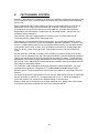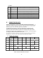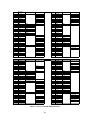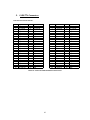
1
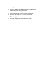
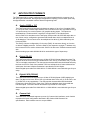
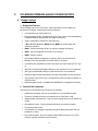
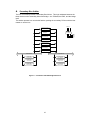
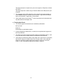
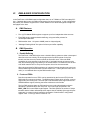
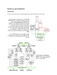
FASTFRAME 1300 HARDWARE MANUAL SPEED AND FLEXIBILITY 30002-00187 COPYRIGHT NOTICE Copyright 2001 by Alacron Inc. All rights reserved. This document, in whole or in part, may not be copied, photocopied, reproduced, translated, or reduced to any other electronic medium or machine-readable form without the express written consent of Alacron Inc. Alacron makes no warranty for the use of its products, assumes no responsibility for any error, which may appear in this document, and makes no commitment to update the information contained herein. Alacron Inc. retains the right to make changes to this manual at any time without notice. Document Name: FastFrame 1300 Hardware Manual Document Number: 30002-00187 Revision History: 2.0 April 22, 2003 Trademarks: Alacron is a registered trademark of Alacron Inc. AltiVec is a trademark of Motorola Inc. Channel Link is a trademark of National Semiconductor CodeWarrior is a registered trademark of Metrowerks Corp. FastChannel is a registered trademark of Alacron Inc. FastSeries is a registered trademark of Alacron Inc. Fast4 , FastFrame 1300 , FastImage , FastI/O , and FastVision are registered trademarks of Alacron Inc. FireWire is a registered trademark of Apple Computer Inc. 3M is a trademark of 3M Company MS DOS is a registered trademark of Microsoft Corporation SelectRAM is a trademark of Xilinx Inc. Solaris is a trademark of Sun Microsystems Inc. TriMedia is a trademark of Philips Electronics North America Corp. Unix is a registered trademark of Sun Microsystems Inc. Virtex is a trademark of Xilinx Inc. Windows , Windows 95 , Windows 98 , Windows 2000 , and Windows NT are trademarks of Microsoft Corporation All trademarks are the property of their respective holders. Alacron Inc. 71 Spit Brook Road, Suite 200 Nashua, NH 03060 USA Telephone: 603-891-2750 Fax: 603-891-2745 Web Site: http://www.alacron.com Email: [email protected] or [email protected] ii TABLE OF CONTENTS Copyright Notice ……………………………………………………………………………… Table of Contents …………………………………………………………………………….. Manual Figures & Tables ……………………………………………………………………. Other Alacron Manuals ………………………………………………………………………. System Requirements ……………………………………………………………………….. I. ii iii v vi vi FASTFRAME 1300 FEATURES............................................................................................. 1 A. FastFrame 1300 Features .............................................................................................. 1 B. Optional Features ........................................................................................................... 2 C. PCI-Version Options....................................................................................................... 2 II. INTRODUCTION TO FASTFRAME 1300 .......................................................................... 3 A. PMC Design ..................................................................................................................... 4 III. DATA ACCESS/CAPTURE ................................................................................................ 5 A. TriMedia-Based Capture ................................................................................................ 5 B. PCI Bridging Logic ......................................................................................................... 5 C. DMA-Based Capture....................................................................................................... 5 IV. INPUT/OUTPUT FORMATS ............................................................................................... 7 A. Analog CVBS or Y/C ....................................................................................................... 7 B. Digital RS-422.................................................................................................................. 7 C. Digital LVDS (RS-644) .................................................................................................... 7 D. Camera Link..................................................................................................................... 7 E. Other Options .................................................................................................................. 8 Optional Video Encoder ........................................................................................... 8 Optional Audio Codec .............................................................................................. 8 Optional FastChannel Header.................................................................................. 8 1. 2. 3. V. PCI BRIDGE/TRIMEDIA-BASED CONFIGURATION....................................................... 9 A. 1. 2. Bridge Features............................................................................................................... 9 Supported Features ................................................................................................. 9 Features Not Supported ........................................................................................... 9 B. Secondary Bus Arbiter ................................................................................................10 C. 1. 2. 3. PCI Bridge Transactions..............................................................................................11 Posted (memory) Writes......................................................................................... 11 Delayed Writes ....................................................................................................... 11 Delayed Reads....................................................................................................... 11 iii 4. D. VI. Prefetchable Reads................................................................................................ 12 Local Registers .............................................................................................................13 DMA-BASED CONFIGURATION .....................................................................................14 A. DMA Features................................................................................................................14 B. 1. 2. DMA Operation..............................................................................................................14 Double Buffering .................................................................................................... 14 Front-end FPGA ..................................................................................................... 14 C. DMA-Engine Block Diagram........................................................................................15 D. DMA-Engine Registers.................................................................................................15 VII. POWER-UP SEQUENCE ..................................................................................................19 A. Power Dissipation.........................................................................................................19 B. FastFrame 1300 Cables ...............................................................................................19 VIII. CLOCK SCHEME...........................................................................................................20 IX. INTERRUPTS.....................................................................................................................21 X. FASTCHANNEL CONTROL .............................................................................................22 A. 1. 2. I²C Address 0 x 40.........................................................................................................23 Byte 1: .................................................................................................................... 23 Byte 2: .................................................................................................................... 23 B. 1. 2. I²C Address 0 x 42.........................................................................................................23 Byte 1: .................................................................................................................... 23 Byte 2: .................................................................................................................... 24 XI. CONNECTOR PIN-OUTS..................................................................................................24 A. Headers and Jumpers ..................................................................................................24 B. VHDCI Connectors........................................................................................................25 C. LVDS/TTL Connectors .................................................................................................27 XII. COMPONENTS replacements.........................................................................................28 A. PCI Components Placements .....................................................................................28 B. PMC Component Placements .....................................................................................29 XIII. TROUBLESHOOTING ...................................................................................................30 XIV. ALACRON TECHNICAL SUPPORT.............................................................................31 A. Contacting Technical Support....................................................................................31 B. Returning Products For Repair Or Replacement.....................................................32 C. Reporting Bugs .............................................................................................................33 iv MANUAL FIGURES AND TABLES Figure Subject Page 1 PCI Block Diagram 2 PMC Block Diagram 4 3 FastFrame 1300 PCI Bridge Data Flow 10 4 DMA Engine Block Diagram 15 5 DMA Address Counter Registers 17 6 Interrupt Connections 21 7 PMC Component Placement 28 8 PMC Component Placement 29 Table 3 Subject Page 1 Local PCI Registers 13 2 DMA-Engine Register Definitions 16 3 DMA Engine Register Locations 18 4 FastFrame 1300 Power Dissipation 19 5 FastFrame 1300 Cables 19 6 Clock Signals 20 7 Control Bits Defined 23 8 Headers and Jumpers 24 9 VHDCI Connector Pin-out 26 10 LVDS Fast Channel Connector Pin-out 27 v OTHER ALACRON MANUALS Alacron manuals cover all aspects of FastSeries hardware and software installation and operation. Call Alacron at 603-891-2750 and ask for the appropriate manuals from the list below if they did not come in your FastSeries shipment. • 30002-00146 FastImage and FastFrame HW Installation for PCI Systems • 30002-00148 ALFAST Runtime Software Programmer’s Guide & Reference • 30002-00150 FastSeries Library User’s Manual • 30002-00153 Fast I/O Hardware User’s Guide • 30002-00155 FastMem Hardware User’s Manual • 30002-00169 ALRT Runtime Software Programmer’s Guide & Reference • 30002-00170 ALRT, ALFAST & FASTLIB Software Installation Manual for Linux • 30002-00171 ALRT, ALFAST, & FASTLIB Software Installation for Windows NT • 30002-00172 FastImage 1300 Hardware User’s Guide • 30002-00173 FastMem Programmer’s Guide & Reference • 30002-00174 FastMem Hardware Installation Manual • 30002-00180 Fast4 1300 Hardware User’s Guide • 30002-00184 FastSeries Getting Started Manual • 30002-00185 FastVision Hardware Installation Manual • 30002-00186 FastVision Software Installation Manual • 30002-00188 FOIL – FastSeries Object Imaging Library SYSTEM REQUIREMENTS • Windows NT with service pack 6 or Windows 2000 with service pack 2 operating systems fully installed. • Minimum 128MB memory installed. • Software Development Environment (SDE) • WinZip software. • Acrobat Reader Software • FastFrame 1300 runtime software is available for Linux, Solaris and Windows NT and Windows NT 2000 operating systems. • Air circulation of at least 200 LFM is required for the Alacron FastFrame 1300 boards. • The operating temperature range of the FastFrame 1300 boards is 0° Celsius to 40° Celsius. vi I. FASTFRAME 1300 FEATURES The Alacron FastFrame 1300 is for original equipment manufacturers and end users who anticipate a demand for diverse I/O requirements and high bandwidth. Available in both analog/digital and digital-only configurations, the FastFrame 1300 with optional Philips TriMedia microprocessor provides for complex image and digital signal processing. A. FastFrame 1300 Features • PMC and PCI Form-Factors available. • Optional on-board TriMedia TM1300 180MHz processor or higher with 16 or 32MB of SDRAM. • Will support future TM1310/20 processors with 64MB. • Capable of over 720 MFLOPS of computational power. • 64 or 32-bit 33MHz PCI interface. • Input/Output via dual (stacked) 68-pin VHDCI connector. • Collects data from up to four (4) simultaneous CVBS or Y/C (S-Video) analog inputs • Collects data from up to 32-bits of LVDS digital input • Collects data from two (2) Camera-Link (Channel Link) inputs. • Two (2) RS-232C serial port interfaces. • Four (4) general-purpose inputs. Four (4) general-purpose outputs. • Two (2) trigger inputs. • Four (4) strobe outputs. • Four (4) clock outputs. • Selectable termination: Allows daisy-chaining of boards. • On-board image-buffering and formatting FPGA, with optional 16 to 128MB of frame memory SDRAM operates at 160MB/s in full-duplex mode or operates at 320MB/s in half-duplex mode. • DMA Engine allows direct-to-host image capture on FastFrame 1300 without TriMedia processor. • 32-bit Fast Channel interface link to Alacron FastImage 1300 or Alacron FastVision capable of 320MB/s peak throughput. • Twelve (12) general purpose LEDs—FPGA controlled (One (1) TriMedia controlled) • Philips SAA7111A Enhanced Video Input Processor 1 B. Optional Features • Optional local TriMedia boot for embedded systems using 2 – 4MB of on-board FLASH accessible via the TriMedia’s X-I/O interface • TriMedia as PCI bus master • Optional stereo Audio Codec up to 20-bit format up to 48K samples/sec • Optional color Video Encoder (PAL or NTSC) from CCIR-656 data C. PCI-Version Options • Optional PMC Site 32Bit/33MHz PCI 32-bit Alacron Fast Channel • Optional LVDS or TTL Alacron Fast Channel headers 2 II. INTRODUCTION TO FASTFRAME 1300 Alacron’s FastFrame-1300 is available in both analog/digital and digital-only configurations for considerable flexibility at a reasonable cost. Depending upon your specific needs and your anticipated applications, your FastFrame 1300 has been configured either with or without a Philips TriMedia TM1300-series microprocessor—an option designed to keep your costs down while providing you with the tools you need either for complex image and signal processing or for frame storage and buffering. The FastFrame 1300 design enables Alacron to offer either the half-length PCI board with TM1300 processor or a simplified setup wherein the board components include four analog inputs, one FPGA, and no processor. In this latter form the analog front end is configured by the host system. RS-232 Driver/ Rcvr To: FPGA CLK Gen CPU_CLK (var) 33 MHz (PCI) 24.576 MHz (EVIP) 100 MHz (FB RAM) VID_CLK (30-60MHz) 3.3V 2.5 or 1.8V 1.5A LDO 2.5V 1.5A LDO FastFrame 1300 PCI Block Diagram 04-Jun-01 Vint for TM1300 Vint for FPGAs I2C Omit for Low Cost ( XC2S100-5FG456C Low Cost Version) Old 'CPLD' Functions LVDS/ RS422 Alacron FastChannel PMC Connector (P4) 64-Bit PCI Core ~22% LUTs ~12%FFs 32-Bits BlockRam FIFO (8x32 Bits) 2 Blocks 64-Bit PCI 33MHz LVDS/ RS422 I2C LED 32-Bit/33MHz PCI LEDs (6) PROM XC17S150AV08C 2,4,8Mx8 Flash (X-I/O) 64-Bit PCI Edge Connector Figure 1 – PCI Block Diagram In addition to the image-processing capabilities of the optional on-board TriMedia TM1300 processor, the FastFrame 1300 provides image data-capture from up to four analog (CVBS or Y/C) sources or from digital sources (Camera-Link or LVDS) of up to 32 bits. The on-board FPGA provides data buffering, formatting, and steering. Camera strobes can be generated from software or from external inputs to the board. The analog front-end is 2 configured using I C—either by the on-board TriMedia processor or from the host via the J4 connector. The data-path FPGA is configured either directly from the PCI interface or by the TriMedia processor 3 PMC P1 & P2 Connectors LVDS/ RS422 LVDS/ RS422 Strobe_Out(4) GP_Out(4) MClk_Out(4) Clk V.34 XC2S150-5FG456C FPGA To: RS-232 Xcvr VID_CLK EEP 24C16 I2C_Ctl (4) Trig_in (2) Strobe_Out (4) (2) CameraLink inputs (2) BlockRam FIFO (8x64 Bits) 8 Blocks CLK 2x CFG 32-Bit I/O 12+ Misc Bits LVDS/ RS422 DMA Controller MCLK Outs(4) Prog_CLK TriMedia TM1300/10/20 BGA292 180MHz (4) 8-bit LVDS or RS422 inputs ChannelLink (2) (4 or 8)M x 16-bit (2x16Mx16 for TM1310) SDRAMs (shares Interconnect Bus) 32-Bit PCI Core ~20% LUTs ~10% FFs (Omit for Low Cost XC2S100) SAA 7111A SAA 7111A (optional ) PROM XC17S100AV08C XC2S150-5FG456C FPGA BlockRam FIFO (32x32 Bits - 4 Blocks) LVDS/ RS422 Upper VHDCI-68 Connector SDRAM Controller 27MHz BlockRam FIFO (32x48 Bits - 6 Blocks) LVDS/ RS422 FastChannel Headers (LVDS, RS422 or TTL) Video Audio Encoder Codec SAA7120 TAS3002 LEDs (6) CFG 100MHz VID_CLK Audio Video Out In/Out (VHDCI) (VHDCI) Video In/Out Omit for Low Cost SAA 7111A RGB 16 - 128MB SDRAM (optional) 32-Bits SAA 7111A RGB In Clks Lower VHDCI-68 Connector (4) CVBS / Y/C inputs Input/output to the board in either configuration, with processor or without processor, uses Alacron’s FastSeries 68-pin VHDCI system and a Camera-Link cable designed specifically for use with the FastFrame 1300. The FastFrame 1300 provides two on-board UARTs, implemented in an FPGA and used to communicate with external devices, including CameraLink cameras. There is no handshaking support. The board can also be configured to allow external RS-232 control of a Camera-Link device which is usually connected to the host PC to allow PC-based applications to control and configure the camera. A. PMC Design The PMC design is simplified—a configuration without a TriMedia processor in which the only components on the board are the four analog inputs and one FPGA. In this configuration, the analog front-end is configured by the host system. RS-232 Driver/ Rcvr To: FPGA CLK Gen CPU_CLK (var) 33 MHz (PCI) 24.576 MHz (EVIP) 100 MHz (FB RAM) VID_CLK (30-60MHz) 3.3V 2.5 or 1.8V 1.5A LDO 2.5V 1.5A LDO FastFrame 1300 PMC Block Diagram 04-Jun-01 Vint for TM1300 Vint for FPGAs I2C (optional ) PROM XC17S100AV08C Omit for Low Cost ( XC2S100-5FG456C Low Cost Version) 32-Bit I/O 12+ Misc Bits V.34 LVDS/ RS422 LVDS/ RS422 XC2S150-5FG456C FPGA LVDS/ RS422 Strobe_Out(4) GP_Out(4) MClk_Out(4) I2C Alacron FastChannel (P4) Connector Figure 2 – PMC Block Diagram 4 32-Bit/33MHz PCI EEP 24C16 2,4,8Mx8 Flash (X-I/O) BlockRam FIFO (8x32 Bits) 2 Blocks 64-Bit PCI 33MHz 64-Bit PCI Core ~22% LUTs ~12%FFs To: RS-232 Xcvr VID_CLK LED I2C_Ctl (4) Trig_in (2) Strobe_Out (4) (2) CameraLink inputs (2) BlockRam FIFO (8x64 Bits) 8 Blocks Clk CFG Old 'CPLD' Functions DMA Controller CLK 2x TriMedia TM1300/10/20 BGA292 180MHz LVDS/ RS422 (4) 8-bit LVDS or RS422 inputs 32-Bits MCLK Outs(4) Prog_CLK BlockRam FIFO (32x32 Bits - 4 Blocks) ChannelLink (2) (4 or 8)M x 16-bit (2x16Mx16 for TM1310) SDRAMs (shares Interconnect Bus) XC2S150-5FG456C FPGA 32-Bit PCI Core ~20% LUTs ~10% FFs (Omit for Low Cost XC2S100) SAA 7111A SAA 7111A SDRAM Controller 27MHz BlockRam FIFO (32x48 Bits - 6 Blocks) LVDS/ RS422 Upper VHDCI-68 Connector Video Audio Encoder Codec SAA7120 TAS3002 LEDs (6) CFG 100MHz VID_CLK Audio Video Out In/Out (VHDCI) (VHDCI) Video In/Out Omit for Low Cost SAA 7111A RGB 16 - 128MB SDRAM (optional) 32-Bits SAA 7111A RGB In Clks Lower VHDCI-68 Connector (4) CVBS / Y/C inputs PMC P1, P2 & P3 Connectors LEDs (6) PROM XC17S150AV08C Indicates Clock Signal III. DATA ACCESS/CAPTURE The FastFrame1300 supports two configurations of data access: • Direct DMA-based Frame-Grabber • TriMedia-based image processing. The DMA-based mode is used in the simplified version of the FastFrame 1300, and is intended for host-based image processing. The TriMedia-based mode is more flexible, allowing some data manipulation before the data goes off-board. Because the TriMedia processor and any device attached to the PMC site is behind a non-transparent bridge, the host’s PCI scan does not see devices behind the bridge (including video-display adapters, etc). Alacron writes device drivers specifically to initialize and communicate with these devices. Contact Alacron for assistance from the engineering staff if your application(s) call for additional specific device drivers. A. TriMedia-Based Capture In TriMedia-based capture, video data is buffered by the TriMedia processor, which can access images in random-access fashion. Data can be transformed or compacted before going off-board: Via the PCI bus, to the PMC site via PCI or Fast Channel, or, in the PCI version of the board, via an optional LVDS Fast Channel connector. The TriMedia-based version of FastFrame 1300 supports a 32-bit PCI bus interface. B. PCI Bridging Logic In the TriMedia-based FastFrame 1300, both the processor and an optional device found on the PMC site are accessible from the host PCI bus. This accessibility is provided by PCI bridging logic in the PCI FPGA. The on-board PCI bridge is designed to function as a non-transparent PCI bridge. Thus it does NOT respond to Type-1 configuration cycles. It only responds to Type-0 cycles to the bridge device itself. The Fast-Frame 1300 device appears to the host as a single PCI device with memory windows. These windows must be configured to be large enough to allow host access to all devices behind the FastFrame 1300 PCI bridge. Downstream configuration cycles to PCI devices on the backside of this bridge are supported via configuration registers. The PCI Bridge-supported features are listed in Section V. C. DMA-Based Capture In Direct Memory Access-based capture, the captured video data is simply buffered, or possibly packed, and made available to a PCI host-based processing engine. This version of the FastFrame 1300 supports 32 and 64-bit PCI interfaces (33MHz). Captured data is sent via DMA to a buffer in host memory, where it is processed by the host processor. The FastFrame 1300 provides DMA master functions. On-board SDRAM buffers allow buffer storage up to 128MB. DMA block lengths of up to 16MB are supported, and individual PCI transactions can burst up to 256 bytes. The DMA controller has two sets of control registers and thus can “double buffer” transfers, interrupting the host when a programmed DMA transfer have been completed, and immediately switching to the other DMA buffer. 5 Alternatively, the host can poll a register to interrogate the DMA status. Additional features include: • PCI master DMA engine with two (2) buffer pointers allows uninterrupted data flow • DMA transfer sizes from 16 bytes to 4MB (must be 4-byte aligned) The video data on the FastFrame 1300 is available only in streaming (serial) format, not in a random-access fashion. The data can go off-board via the host PCI bus or, in the PCI version, via an optional LVDS Fast-Channel connector. In the DMA-based capture configuration, only the FastFrame 1300 DMA registers are available from the PCI bus. The PMC site option is not supported. 6 IV. INPUT/OUTPUT FORMATS The FastFrame1300 is usually configured for your particular application(s) to support one of the input types listed below, although special applications requiring a mix of these inputs may be supported after consultation with the Alacron engineering staff. A. Analog CVBS or Y/C The FastFrame1300 board supports simultaneous capture of up to four (4) analog CVBS or Y/C inputs. Each of these input channels can come from one of four (4) CVBS or two (2) Y/C input sources, for a total of sixteen (16) possible analog inputs. The inputs are terminated into 75 ohms and A/C coupled to a Philips SAA7111A video decoder. All four SAA7111A decoders on the FastFrame 1300 provide 8-bit CCIR 656-style data, or two of them can be configured to generate RGB format data, which is multiplexed into a 16-bit data bus. This bus can then be de-multiplexed into three (3) 8-bit channels by the front-end FPGA. 2 The SAA7111As are configured by I C from the (PMC) J4 connector directly, or from the 2 on-board TriMedia processor. Since the SAA7111As respond to a single I C address only, the on-board FPGA is used to select which SAA7111A device the TriMedia communicates with. Alacron analog-input cable #10024-00162 is used with this type of input setup. B. Digital RS-422 The FastFrame1300 board supports up to 32 bits of RS-422-format digital-input data. The data can be in the form of four (4) individual 8-bit TAPs, two (2) 16-bit TAPs, one (1) 32-bit TAP or a suitable combination. The data can then be assembled into the desired format by the front-end FPGA. Each of the possible TAPs has individual clock, frame-valid and linevalid inputs. On-board 100ohm termination is provided for RS-422 inputs. Alacron digital-input cable P/N 10024-00161 or 10024-00224 is used with this type of input setup. C. Digital LVDS (RS-644) The FastFrame1300 board supports up to 32 bits of RS-644-format (LVDS) digital-input data. The data can be in the form of four (4) individual 8-bit TAPs, two (2) 16-bit TAPs, one (1) 32-Bit TAP or any combination. The data can then be assembled into the desired format by the front-end FPGA. Each of the TAPs has individual clock, frame-valid and line-valid inputs. On-board 100ohm termination is provided for LVDS inputs. Alacron digital-input cable P/N 10024-00161 or 10024-00224 is used with this type of input setup. D. Camera Link The FastFrame 1300 board supports up to two (2) Camera-Link interfaces, each of which represents the base configuration described in the October 2000 Camera Link specifications. Each interface can run at up to 66MHz. 7 Each Camera-Link interface supports 24 bits of data, and four bits of control, as well as the bi-directional serial communications interface and CC1 through CC4 signals. Termination for all Camera-Link signals is provided on board. Alacron supplies a special Camera-Link cable to be used only with the FastFrame 1300. The FastFrame 1300 Camera-Link cable can be used for either of the board’s CameraLink interfaces. It connects to a standard 26-pin 3M MDR connector. Alacron Camera-Link cable #10024-00250 is used with the Camera-Link setup. E. Other Options 1. Optional Video Encoder The FastFrame1300 board supports an optional NTSC/PAL Video Encoder, which will generate a CVBS or Y/C (S-video) output stream from a CCIR 656 data stream. The encoder chip can also generate NABTS Teletext-encoded data on the video signal. The video-output signal replaces the secondary video input of the last CVBS input channel on the VHDCI connector. This design uses a Philips SAA7121, and is configured 2 via I C at address 0x88 2. Optional Audio Codec The FastFrame1300 board supports an optional 24-bit stereo Audio CODEC to allow analog audio signals to be encoded or decoded into an I2-S format serial stream for processing by the TriMedia or- by the on-board FPGA. The CODEC can handle sampling at up to 48KHz. The audio channels appear on the VHDCI connector. The design uses a Texas Instruments TAS3002 device, and is 2 configured via I C at address 0x6A. 3. Optional FastChannel Header The FastFrame1300 board optionally supports up to 32-bits of LVDS or TTL Fast Channel data via dual 50-pin headers. The direction of this Fast-Channel interface is 2 selectable on a byte (8-bit) boundary via I C at address 0x40 & 0x42. This option prevents normal operation of the PMC Fast Channel, although the PMC PCI operation is not affected. 8 V. PCI BRIDGE/TRIMEDIA-BASED CONFIGURATION A. Bridge Features 1. Supported Features The PCI Bridge logic on the Fast-Frame 1300 implements a 32-bit 33MHz nontransparent PCI bridge, supporting the following features: • 3.3V operation with 5.0V tolerant I/O • Non-transparent bridge. Appears as a single Type-0 Device, allowing address translation between primary and secondary side devices. • Type-0 configuration registers for each direction • 3 Base Address Registers (BAR0 through BAR2) on both primary and secondary interface • BAR0: Used by the bridge as the 1K memory-mapped CSR space. • BAR1: Can be configured as memory or I/O window. • BAR2: Memory window • Direct Offset address translation for memory and I/O in both directions • Memory block size adjustable from 256K bytes to 2G bytes. • I/O window size adjustable from 64 to 256 bytes (PCI-spec maximum for Type 0) • 256 bytes of Posted Write data buffering in both directions for one transaction. • 256 bytes of Read data buffering in both directions for one transaction. • Supports single delayed transactions (I/O and configuration) in both directions. • Can generate Type-0 and Type-1 configuration cycles from either interface via CSR accesses. • BAR sizes/types stored in TriMedia Boot EEPROM for configuration flexibility 2. Features Not Supported The FastFrame-1300 Bridge does not support the following: • Subtractive Decoding, which is not needed for a non-transparent bridge • Exclusive (LOCK#) access is not supported in the FastFrame 1300 • Multiple delayed transactions. Only one active transaction per side; others are retried. • Dual-address cycles. Ignores as target and does not initiate as master. • Fast back-to-back cycles. • Concatenation or merging of separate contiguous data transactions into one transaction or burst. • Direct VGA Support. Does not support VGA Palette snooping or I/O, which must be explicitly mapped through a window. 9 B. Secondary Bus Arbiter The PCI FPGA also provides a Secondary Bus Arbiter. This logic arbitrates between the three devices on the secondary side of the bridge – the TriMedia, the PMC, and the bridge itself. The arbiter operates in a round-robin fashion, parking the secondary PCI bus with the last master to use the bus. REQ<0-2> Downstream Posted W rite (256 Bytes) Upstream Read Buffer (256 Bytes) Secondary Bus Arbiter GNT<0-2> Downstream Read Buffer (256 Bytes) Upstream Posted W rite (256 Bytes) Downstream Delayed Buffer (4 Bytes) Upstream Delayed Buffer (4 Bytes) Bridge Control CSR Registers (128B) 32-Bit 33MHz PCI 32-Bit 33MHz PCI Primary-Side Config Registers Secondary-Side Config Registers Primary-Side Target Control Secondary-Side Target Control Primary-Side Master Control Secondary-Side Master Control Figure 3 -- FastFrame 1300 PCI Bridge Data Flow 10 C. PCI Bridge Transactions The Fast-Frame PCI Bridge handles four types of PCI transactions. The behavior of the bridge during each of these transactions is described on the following pages. Transactions are performed in the following order: • Posted Writes must complete before any other transactions (other than Delayed Write Completion) are accepted. • Since the bridge has only single transaction pipelines, transactions on either side are accepted in the order they are presented, with the exception of Posted Writes. 1. Posted (memory) Writes • The bridge accepts burst-write data into a 256-byte (64 data phases) buffer, without wait states, until the buffer is full or a cache-line boundary is crossed (i.e. 4, 8, 16 or 32 D-words per configuration space). • The bridge responds with Target Disconnect if the buffer is filled. The bridge accepts only ONE posted write transaction (up to 256 bytes) at a time. • Once all, or at least the “CacheLineSize” bytes, have been written, the target write may begin. • If the target exceeds the max number of retries (2 ), the transaction is terminated and SERR# is asserted (if enabled) on the initiating bus. If the target aborts the transfer, SERR# is also asserted. • Memory Write and Invalidate (MWI) commands are treated the same as MW commands. 24 2. Delayed Writes • The bridge treats I/O writes and CSR-generated configuration writes as singlecycle “Delayed Writes.” The sequence of a Delayed Write is as follows. • The bridge accepts the write address, C/BEs and data, and then terminates the initiator cycle as a Retry. • The bridge attempts to complete the cycle on the target bus, and responds to the initiator with “Retry.” • The bridge responds to initiator retry (of identical address, C/BE and Data) with a Cycle Complete. • The response to the initiator depends on the outcome of the target transfer. A normal TRDY# response indicates a normal transfer. Target Abort and Master Abort are reported as “Target Abort” to the initiator. • If the initiator does not retry within 2 clocks, the posted write is discarded and any written data is lost, although the target write may have been performed. In this case SERR# is asserted, if enabled. 15 3. Delayed Reads • The bridge treats I/O reads and CSR-generated configuration writes as singlecycle “Delayed Reads.” The sequence of a Delayed Read is as follows: The bridge accepts the read address and C/BEs, and then terminates the initiator cycle as a Retry. 11 The bridge attempts to complete the cycle on the target bus. Responds to initiator with “Retry.” The bridge responds to initiator retry (of identical address and C/BE) with a Cycle Complete. • The response to the initiator depends on the outcome of the target transfer. A normal TRDY# response indicates a normal transfer. Target Abort and Master Abort are reported as “Target Abort” to the initiator. • If the initiator does not retry within 2 clocks, the posted read is discarded and any data read from the target is lost. 15 4. Prefetchable Reads • The following types of transactions are considered prefetchable: Memory Read Read-Line Read-Multiple to prefetchable regions. • I/O and configuration transactions, or reads from non-prefetchable regions will NOT be prefetched. • The bridge will perform limited speculative reads to prefetchable regions. It will fill up to a cache-line boundary and then terminate the target transfer. • If the bridge is still delivering data to the initiator at the same time it is accepting data from the target, the bridge enters Flow-Through mode. In this mode the bridge will continue to transfer data until the buffer is empty for more than 7 cycles, or until a 4KB address alignment boundary is reached. 12 D. Local Registers In addition to the configuration registers required by the PCI Bridge specification, the following local registers are defined. They have the same designation as in the DMA configuration. BAR 0 Offset: Register 0x0000 DMA_ID_STATUS 0x0010 FE_CONFIG (download) 0x0020 FE_CONTROL 0x0030 FE_SDRAM_SEG 0x0040 UART_I2C_CTL 0x0050 GPIO_REG 0x0060 STB_CTL 0x0070 STB_PRE_SW 0x0090 STRB12_START 0x00A0 STRB12_ENDPD 0x00B0 STRB34_START 0x00C0 STRB34_ENDPD Table 1 – Local PCI Registers 13 VI. DMA-BASED CONFIGURATION In the FastFrame 1300 DMA-based configuration there is no TriMedia or PMC secondary-PCI bus. Captured data is sent via DMA to host memory for host processing. In this configuration the primary PCI interface supports 64 or 32-Bit 33MHz PCIs to allow the highest average PCI throughput to the host. A. DMA Features • Four (4) PCI Master DMA engines to support up to four independent video sources. • Each DMA engine supports double-buffering, using two buffer pointers for uninterrupted data flow. • DMA transfer sizes: 16 bytes to 64MB (must be 4-byte aligned) • “Message-Passing-Mode”-like option for frame-per-buffer capability B. DMA Operation 1. Double Buffering The FastFrame 1300 DMA engine uses a double-buffering scheme to allow uninterrupted data flow to the host. Initially, the host programs the first buffer pointer for the first transfer, and the second to continue where the first buffer ends. When the DMA completes the count specified in the first buffer, it (optionally) sends an interrupt to the host, and switches (ping-pong fashion) to the second buffer. This allows the host to have a full buffer transfer-time to set up the first pointer in time for the next transfer. When the second buffer DMA completes, an (optional) interrupt is again sent to the host and the DMA engine switches back to buffer number one. If at any time the buffer is not valid (i.e. not initialized after use) the DMA transfer stops. 2. Front-end FPGA Data from separate front-end TAPs can be assembled by the front-end FPGA for the DMA engines to stream to the host. The DMA engines indicate which of buffer- memory regions they are reading from. The front-end FPGA translates these region-selects into SDRAM address regions, allowing the buffer architecture to be flexible. The four DMA engines share the PCI interface via a round-robin arbitration scheme. Arbitration is performed after each PCI burst. The burst length is specified in the BRST_LEN field in each DMA length Register. This field specifies the number of 4-byte transfers that the initiator will attempt when capture data is available (4 through 64 bytes supported). In general it should match the destination “CacheLineSize” configuration register value. A Zero (0) value is treated as “16.” 14 C. DMA-Engine Block Diagram INTER-FPGA Interface (32-Bit Data) 32 Bits INTER_X [10:1] VID_CLK (75MHz) READ (CTL[3:0]) EMPTY (CTL[7:4]) DMA Arbiter 32 Bit Register 32 Bit Register Data Flow Machine Other Regs 32 Bits DMA_ADDR3 MUX DMA_ADDR2 32 Bits DMA_ADDR1 DMA_ADDR4 64 Bits BlockRam FIFO 64Bits x 256 (4 Blocks) 32 Bits PCI Addr [31:0] PCI Initiator Machine 32-Bit Register 32 Bits CLK {ADDR31-0, ADIO63-0, PCI_CMD etc} 32-Bits {AD63-0, CBE7-0, FRAME etc} Figure 4 -- DMA Engine Block Diagram D. DMA-Engine Registers Each of the four DMA engines has two target-address and DMA-length/control registers (for double-buffering). The length/control registers provide status bits (Error, Done) and the count remaining in the transfer. The Error field will indicate the type of PCI error that was encountered, if any. 15 PCI_CLK (33MHz) Xilinx PCI-64 PCI Core Interface (33MHz) DMA_ID_STATUS RSVD + ID[7:0] CLK SEL[2:0] BRST_LEN [3:0] ANY ERROR ANY BUSY ANY DONE INT ENA Int 1 Int 0 LED[5:0] FE_CONFIG (download) RSVD DONE (R/O) CS_EN (R/W) INIT (R/O) CCLK (R/W) PROG (R/W) FE_CONTROL RSVD <TBD> MSG_PASS CAPTURE_ON REG_R/W REG_ADDR(4) REG_DATA(16) FE_SDRAM_SEG RSVD SDRAM SEGMENT (15 Bits) 00 UART_I2C_CTL DO UART RSVD UART R/W UART ADDR(4) UART DATA(8) DO 2 IC 2 2 IC ADDR(7) 2 I C_R/W IC DATA(8) GPIO_REG RSVD GPIN[3:0] (R/O) GPOUT[3:0] (R/W) STB_CTL RSVD STB3 FUNC STB4ENA STB4POL STB3ENA STB3POL EDGE3&4 TRG_SRC(4,3) + STB1 FUNC STB2ENA STB2POL STB1ENA STB1POL EDGE1&2 TRG_SRC(2,1) STB_PRE_SW RSVD SW_TRIG3&4 SW_TRIG1&2 PRESCALE (11 Bits) STRB12_START ST2_START (16 Bits) ST1_END (16 Bits) STRB12_ENDPD ST12_PERIOD (16 Bits) ST2_END (16 Bits) STRB34_START ST4_START (16 Bits) ST3_END (16 Bits) STRB34_ENDPD ST34_PERIOD (16 Bits) ST4_END (16 Bits) 16 DMA_TGT_ADDR (1-4, A/B) PCI Target Address (30 Bits) 00 DMA_TGT_CNTRL (1-4, A/B) PCIRSVD ERRO PCI ERROS DONE GO DMA Length (24 Bits) 00 Table 2 – DMA-Engine Register Definitions Host Interrupts can be selected or disabled (Interrupt A through Interrupt D). When interrupts are disabled, the host may poll the DONE bit to determine when a transfer has completed. Note that polling cycles reduce effective DMA bandwidth accordingly. The ID is a field used by driver software to identify customized FPGA design variations. The LED field can be used to interrogate or set LEDs on the board. Other application-specific registers may be added as required. Details of the PCI Initiator Address Register are in the diagram below. Done_4 Done_3 Done_2 A/B Buffer Select Chan Sel[1:0] PCI Address Counter (30 Bits, up) 33MHz Transfer Count (24 Bits, down) Done Done_1 2: 1 MUX Target Addr XFER_DONE 2: 1 MUX DMA Length PCI Address Counter (30 Bits, up) 33MHz DMA 1 30 Bit Addr Target Addr Transfer Count (24 Bits, down) Done DMA 2 30 Bit Addr 2: 1 MUX DMA Length 30 Bit PCI Addr DMA 2 30 Bit Addr Same for DMA Channels 2 thru 4 DMA 2 30 Bit Addr Figure 5 – DMA Address Counter Registers The DMA interface is accessible from the PCI interface through PCI Base Address Register windows. The control registers are located in BAR 0 (0x10) which is 32-bit memory-mapped and non-prefetchable. 17 Data is mastered (PCI initiator) from the DMA controller, and thus does not require a Base Address allocation. Base Address Register 1 (BAR 1, 0x14) allows optional access to frame-buffer memory. It is 32-bit memory-mapped and non-prefetchable. This access is limited to 4KB windows. A segment register must be set to select the desired 4KB region for random access. The following table shows the memory offsets of the DMA registers at BAR 0. Other application-specific registers may be added as required in the space from 0x004 thru 0x00FC. These specific designs can be identified via the 8-bit “ID” register. BAR 0 Offset: Register 0x0000 DMA_ID_STATUS 0x0010 FE_CONFIG (download) 0x0020 FE_CONTROL 0x0030 FE_SDRAM_SEG 0x0040 UART_I2C_CTL 0x0050 GPIO_REG 0x0060 STB1_4CTL 0x0070 STB_PRE_SW 0x0090 STRB12_START 0x00A0 STRB12_ENDPD 0x00B0 STRB34_START 0x00C0 ... STRB34_ENDPD ... 0x0100 DMA_TGT_ADDR1A 0x0110 DMA_TGT_CTL1A 0x0120 DMA_TGT_ADDR2A 0x0130 DMA_TGT_CTL2A 0x0140 DMA_TGT_ADDR3A 0x0150 DMA_TGT_CTL3A 0x0160 DMA_TGT_ADDR4A 0x0170 DMA_TGT_CTL4A 0x0200 DMA_TGT_ADDR1B 0x0210 DMA_TGT_CTL1B 0x0220 DMA_TGT_ADDR2B 0x0230 DMA_TGT_CTL2B 0x0240 DMA_TGT_ADDR3B 0x0250 DMA_TGT_CTL3B 0x0260 DMA_TGT_ADDR4B 0x0270 DMA_TGT_CTL4B ... ... Table 3 -- DMA Engine Register Locations (BAR 0) 18 VII. POWER-UP SEQUENCE The FastFrame 1300 software-controlled procedure for power-up and module initialization follows this sequence: • 3.3V and 5.0V Power Applied • 2.5/1.8V power stabilizes. The time this takes depends on the 3.3V ramp-rate. • PCI FPGA configures from EPROM. • TM1300 reads EEP configuration data • Host processor performs BIOS scan and configures TM1300 PCI resources, if present. • Host processor loads TriMedia program into TriMedia RAM, and runs. • TriMedia initialization code configures front-end FPGA (optional EEPROM configuration). • Software initializes on-board registers via TriMedia I C controller. • Data capture may begin. A. 2 Power Dissipation The FastFrame 1300 will dissipate power approximately as shown below: Version +5V Power +3.3V Power +/-12V PCI 16W 11W +/- 30mA PMC 5W 10W +/- 30mA Table 4 - Approximate Power Dissipation Both the PCI and PMC versions of FastFrame 1300 have auxiliary power connectors. The PMC auxiliary power connector is for use in systems that cannot supply 3.3V via the PMC connector. The PCI auxiliary power connector is used to provide supplemental power when the PMC site is used. See the Installation Manual, #30002-00185 for installation assistance. B. FastFrame 1300 Cables The appropriate cables from the list below have been included in your FastFrame 1300 shipment. If you need additional cables, contact Alacron Sales or Technical Support. Alacron Part Number Cable Use 100024-00160 DC Power Cable 100024-00161 Digital Input Cable 100024-00162 Analog Input Cable 100024-00224 Digital-In Adapter Cable 100024-00250 Camera-Link Cable Table 5 – FastFrame 1300 Cables 19 VIII. CLOCK SCHEME The FastFrame 1300 design takes advantage of the high data rates possible with the TM1300 processor, while enabling tight control of the timing on high-speed buses, especially when utilizing the Alacron Fast Channel connector. The clocks are selected and generated through the FPGAs. The on-board clock-generator chips (Cypress CY2292) generate the following clocks: Clock Signal Frequency Used by: SDRAM Clk 100.00MHz Buffer SDRAM, FPGA CPU_CLK 47.666MHz, Selectable TM1300 EVIP_CLK 24.576MHz SAA7111A’s V34_CLK 20.000MHz TM1300, PCI_FPGA VID_CLK (2) 40-80MHz, Selectable FPGAs, TM1300, FastChan, VideoOut PCI_CLK 33MHz PCI_FPGA, TriMedia, PMC Site UART_CLK 6.144MHz PCI_FPGA The following clocks are also available on the FastFrame 1300 board: Clock Signal Freq Sourced by => Used By: TM_VOCLK 1-80MHz S/W Select TM1300 => FE_FPGA, FastChan, VideoOut TM_AIOSCK 1-40MHz S/W Select TM1300 => FE_FPGA, TM_AOSCK 1-40MHz S/W Select TM1300 => FE_FPGA, AUDIO_CODEC FECLK1 1-75MHZ (per Conf) (ChanLnk1 / PixClk1 –or- FchanClkA) => FE_FPGA* FECLK2 1-75MHZ (per Conf) (ChanLnk2 / PixClk4 –or- VID_CLK) => FE_FPGA* PIX_CLK(2,3) 1-75MHz (Analog / Dig Vid In) => FPGA_I/O** FchanClk(B,C) 1-75MHz FastChan => FPGA_I/O** Table 6 – Clock Signals Clocks above with one asterisk ( * ) are multiplexed (CMOS switch); selectable by the FPGA. Only one of the two selections is available at any given time. Channel Link (Camera Link), differential and analog inputs are mutually exclusive population options. Clocks above with two asterisks (**) connect to FPGA I/O pins, not to dedicated global clocks, so care must be taken to prevent problems due to clock skew in the FPGA logic using these clocks. The Front-End FPGA has the following clock inputs available: • PIX_CLK1 thru PIX_CLK4 (from video inputs) • SDRAM Clock (approx 100MHz) for Frame Buffer • TriMedia VO_CLK • FastChannel Clks (From J4) VID_CLK – Selectable Video Clock from CLK Generator The PCI FPGA has the following clock inputs available: • Inter-FPGA CLK (from F.E. FPGA) • V.34 CLK (20MHz from ClkGen) 20 • VID_CLK – Selectable Video Clock from CLK Generator • PCI_CLK (33MHz for secondary PCI interface or Primary Master) • UART_CLK (6.144 MHz for UART timing) IX. INTERRUPTS The interrupts from the various devices on the FastFrame 1300 board are connected as shown below. PMC Site C A A B C B PCI FPGA D C TriMedia Host Connector A D + LED Figure 6 – Interrupt Connections • This configuration allows flexible connection between host, PMC and TriMedia interrupt sources (open drain), and handlers via the PCI FPGA. • The TriMedia interrupt “D” pin is also connected to an LED for debugging purposes. 21 X. FASTCHANNEL CONTROL Alacron’s Fast Channel is a mechanism for Alacron’s FastSeries components, like those found on the FastFrame 1300, to communicate with the processing environment without impacting the PCI bus. When implemented within a high-performance DSP or imaging application, the bus form of data transfer can be subject to bus saturation and contention. However point-to-point communication directly from the data source to the data sink, with each interconnection supporting its own data transfer—isolated from any other data transfer—can prevent such contention and bus saturation. Fast Channel is Alacron’s implementation of a point-to-point, or point-to-many-points, connection between a data source and its data sinks. Fast Channel is a cost-effective interconnects solution. It is configurable at startup, and no special hardware is needed for source and destination addresses, arbitration, or control of the channel. Simple software protocols can be implemented because the only operation allowed is the transfer of one “word” of data. The Fast Channel is composed of a parallel data path from 1 to 32 bits, a clock, and a data valid. Specifications will vary with environment and usage. An input data rate of 320 MB, or anything over 133 MB, is too high for transfer over the PCI bus, but it can be transferred over the Fast Channel at 80 MHz—with the additional benefits of isolating the transfer from the host CPU and without impacting PCI activity. In data-intensive applications, Fast Channel’s higher bandwidth will provide significant user savings over using the PCI bus, even if additional CPUs and cameras are installed to achieve the higher rates the Fast Channel is designed to handle. The FastFrame 1300 configuration allows 8-bit granularity in data-path direction. The byte 2 lane and control signals are configured via I C (address 0x40 and 0x42) using a Philips PCF8575 device. These registers also control which clock signals are connected to the Fast Channel. 2 The control registers are implemented in two I C devices. Each device provides 16 control bits 2 that can be written or read via I C. All register bits power up as “1,” effectively disabling all (active low) signals. The control bits are defined starting on the next page. Writes to either device must be done as a single multi-byte write. Reads can be either single or multi-byte depending on whether the first 8 or all 16 bits are desired. 22 A. I²C Address 0 x 40 1. Byte 1: Bit # Signal Name Meaning: 7 ~FC3_IN When ‘0’ connects FC data bits D7 thru D0 to FPGA inputs 3124 6 ~FC2_IN When ‘0’ connects FC data bits D7 thru D0 to FPGA inputs 2316 5 ~FC1_IN When ‘0’ connects FC data bits D7 thru D0 to FPGA inputs 1508 4 ~FC0_IN When ‘0’ connects FC data bits D7 thru D0 to FPGA inputs 0700 3 ~FC3_OUT When ‘0’ connects FPGA bits 31-24 to FC data bits D7 thru D0 2 ~FC2_OUT When ‘0’ connects FPGA bits 23-16 to FC data bits C7 thru C0 1 ~FC1_OUT When ‘0’ connects FPGA bits 15-08 to FC data bits B7 thru B0 0 ~FC0_OUT When ‘0’ connects FPGA bits 07-00 to FC data bits A7 thru A0 2. Byte 2: Bit # Signal Name Meaning: 7 ~FC_CKC7 When ‘0’ connects VID_CLK 6 ~FC_CKC6 When ‘0’ connects TM_VOCLK to FC_CLKC (input OR output) 5 ~FC_CKC5 When ‘0’ connects VID_CLK 4 3 ~FC_CKC4 ~FC_CKC3 When ‘0’ connects TM_VOCLK to FC_CLKA (input OR output) When ‘0’ connects FCHAN_CKD to FC_CLKD (input OR output) 2 ~FC_CKC2 When ‘0’ connects FCHAN_CKC to FC_CLKC (input OR output) 1 ~FC_CKC1 When ‘0’ connects FCHAN_CKB to FC_CLKB (input OR output) 0 ~FC_CKC0 When ‘0’ connects FCHAN_CKA to FC_CLKA (input OR output) B. I²C Address 0 x 42 to FC_CLKD (input OR output) to FC_CLKB (input OR output) 1. Byte 1: Bit # Signal Name Meaning: 7 ~FC_TRM_ENA 1 When ‘0’ enables LVDS termination of FCHAN B7 thru B0 6 ~FC_TRM_ENA 0 When ‘0’ enables LVDS termination of FCHAN A7 thru A0 5 ~FX5_OUT When ‘0’ enables C03 and C07 outputs from FPGA 4 ~FX4_OUT When ‘0’ enables C02 and C06 outputs from FPGA 3 ~FX3_OUT When ‘0’ enables PIXCK4 and PIXCK2 outputs 2 ~FX2_OUT When ‘0’ enables C01 and C05 outputs from FPGA 1 ~FX1_OUT When ‘0’ enables C00 and C04 outputs from FPGA 0 ~FX0_OUT When ‘0’ enables PIXCK3 and PIXCK1 outputs 23 2. Byte 2: Bit # Signal Name Meaning: 7 ~FC_TRM_ENA 3 When ‘0’ enables LVDS termination of FCHAN D7 thru D0 6 ~FC_TRM_ENA 2 When ‘0’ enables LVDS termination of FCHAN C7 thru C0 5 ~FX5_IN When ‘0’ enables C03 and C07 inputs to FPGA 4 ~FX4_IN When ‘0’ enables C02 and C06 inputs to FPGA 3 ~FX3_IN When ‘0’ enables PIXCK4 and PIXCK2 inputs to FPGA 2 ~FX2_IN When ‘0’ enables C01 and C05 inputs to FPGA 1 ~FX1_IN When ‘0’ enables C00 and C04 inputs to FPGA 0 ~FX0_IN When ‘0’ enables PIXCK3 and PIXCK1 inputs to FPGA XI. CONNECTOR PIN-OUTS The pin-out of the FastFrame 1300 dual 68-pin VHDCI connector retains the same pin assignments for digital inputs (4 TAPs), including GPINs and GPOUTs, Strobes and Trig_Ins, as are found on Alacron’s FastImage 1300 board. Analog inputs retain the original Alacron FastSeries pin-out for the CVBS input, extended to four positions. The biggest difference between the FastFrame 1300 and Alacron’s FastImage 1300 connectors is in the Camera-Link pin-out. Rather than having a separate J2 connector, Camera-link signals replace digital-input signals on the FastFrame 1300 J1A/B connector. The FastFrame 1300 has a new, straightforward pin-out configuration. The RS-232 interfaces are optional, and replace GPIN pins when they are used. The LVDS/TTL Fast Channel connectors use the same connectors and pin-out as Alacron’s FastImage 1300. However control of their direction and enables have changed. A. Headers and Jumpers Conn Use Pin 1 Pin 2 Pin 3 Pin 4 Pin 5 P1 Aux Power 3.3VDC in GND GND 5.0VDC in N/A P2 LED Test Points LED01 LED03 LED04 LED09 LED10 GND P3 Xilinx JTAG TRST TCK TMS TDI TDO GND P4 TM1300 EEProm Jumper 1-2 for Write Enable. N/C P5 TM1300 JTAG J1A/B Term Ena TRST TMS P6 TCK Jumper 1-2 to terminate Taps 1 & 2 Jumper 5-6 for Default (no EEProm) TDI N/C Table 8 – FastFrame 1300 Headers and Jumpers 24 Pin 6 TDO GND Jumper 5-6 to terminate Taps 3 & 4 B. VHDCI Connectors The pin-out of the FastFrame 1300 dual 68-pin VHDCI connector is shown in Table 9 on the next page. 25 Pin # 1 2 3 4 5 6 7 8 9 10 11 12 13 14 15 16 17 18 19 20 21 22 23 24 25 26 27 28 29 30 31 32 33 34 J1A Pinout Dig In Pin T1_LVAL+ T1_LVAL_ T1_FVAL+ T1_FVAL_ T1_PXCK+ T1_PXCK_ GPIN1+ GPIN1GND T1_D0+ T1_D0T1_D1+ T1_D1T1_D2+ T1_D2T1_D3+ T1_D3T1_D4+ T1_D4T1_D5+ T1_D5T1_D6+ T1_D6T1_D7+ T1_D7GND X_TRIG1+ X_TRIG1GPIN5+ GPIN5GPOUT1+ GPOUT1GPOUT2+ GPOUT2- Pin # 1 2 3 4 5 6 7 8 9 10 11 12 13 14 15 16 17 18 19 20 21 22 23 24 25 26 27 28 29 30 31 32 33 34 J1B Pinout Dig In Pin T3_LVAL+ T3_LVAL_ T3_FVAL+ T3_FVAL_ T3_PXCK+ T3_PXCK_ GPIN3+ GPIN3GND T3_D0+ T3_D0T3_D1+ T3_D1T3_D2+ T3_D2T3_D3+ T3_D3T3_D4+ T3_D4T3_D5+ T3_D5T3_D6+ T3_D6T3_D7+ T3_D7GND X_TRIG2+ X_TRIG2GPIN6+ GPIN6GPOUT3+ GPOUT3GPOUT4+ GPOUT4- Analog Pin Cam-Link Pin XACLK+ XACLK- GND YIN1A+ YIN1AYIN1B+ YIN1BCIN1A+ CIN1ACIN1B+ CIN1B- GND XA0+ XA0XA1+ XA1XA2+ XA2XA3+ XA3GND GND SERTFGA+ SERTFGASERTCA+ SERTCACC1A+ CC1A- Analog Pin Cam-Link Pin XBCLK+ XBCLK- GND YIN3A+ YIN3AYIN3B+ YIN3BCIN3A+ CIN3ACIN3B/CVBS_OUT+ CIN3B/CVBS_OUT- GND GND XB0+ XB0XB1+ XB1XB2+ XB2XB3+ XB3GND SERTFGB+ SERTFGBSERTCB+ SERTCBCC1B+ CC1B- Pin # 35 36 37 38 39 40 41 42 43 44 45 46 47 48 49 50 51 52 53 54 55 56 57 58 59 60 61 62 63 64 65 66 67 68 Dig In Pin STROBE1+ STROBE1STROBE2+ STROBE2MSTR_CK1+ MSTR_CK1MSTR_CK2+ MSTR_CK2GND T2_D7+ T2_D7T2_D6+ T2_D6T2_D5+ T2_D5T2_D4+ T2_D4T2_D3+ T2_D3T2_D2+ T2_D2T2_D1+ T2_D1T2_D0+ T2_D0GND GPIN2+ GPIN2T2_LVAL+ T2_LVAL_ T2_FVAL+ T2_FVAL_ T2_PXCK+ T2_PXCK_ Pin # 35 36 37 38 39 40 41 42 43 44 45 46 47 48 49 50 51 52 53 54 55 56 57 58 59 60 61 62 63 64 65 66 67 68 Dig In Pin STROBE3+ STROBE3STROBE4+ STROBE4MSTR_CK3+ MSTR_CK3MSTR_CK4+ MSTR_CK4GND T4_D7+ T4_D7T4_D6+ T4_D6T4_D5+ T4_D5T4_D4+ T4_D4T4_D3+ T4_D3T4_D2+ T4_D2T4_D1+ T4_D1T4_D0+ T4_D0GND GPIN4+ GPIN4T4_LVAL+ T4_LVAL_ T4_FVAL+ T4_FVAL_ T4_PXCK+ T4_PXCK_ Table 9 – Pinout of J1A/J1B VHDCI Connector 26 Analog Pin Cam-Link Pin GND CC2A+ CC2ACC2A+ CC2ACC3A+ CC3AGND CIN2B+ CIN2BCIN2A+ CIN2AYIN2B+ YIN2BYIN2A+ YIN2AGND Analog Pin GND AINL AGND AINR AGND AOUTL AGND AOUTR AGND CIN/OUT4B+ CIN/OUT4BCIN4A+ CIN4AYIN/OUT4B+ YIN/OUT4BYIN4A+ YIN4AGND GND RS-232A_RXD RS-232A_TXD Cam-Link Pin CC2B+ CC2BCC2B+ CC2BCC3B+ CC3BGND GND RS-232B_RXD RS-232B_TXD RS-232C_RXD RS-232C_TXD RS-232D_RXD RS-232E_RXD C. LVDS/TTL Connectors Fast-Channel Connector Pin-Out J2 Pin 1 2 3 4 5 6 7 8 9 10 11 12 13 14 15 16 17 18 19 20 21 22 23 24 25 Signal FC_DAT0P FC_DAT0N FC_DAT1P FC_DAT1N FC_DAT2P FC_DAT2N FC_DAT3P FC_DAT3N FC_DAT4P FC_DAT4N FC_DAT5P FC_DAT5N FC_DAT6P FC_DAT6N FC_DAT7P FC_DAT7N GND GND FC_DAT8P FC_DAT8N FC_DAT9P FC_DAT9N FC_DAT10P FC_DAT10N FC_DAT11P J2 Pin 26 27 28 29 30 31 32 33 34 35 36 37 38 39 40 41 42 43 44 45 46 47 48 49 50 Signal FC_DAT11N FC_DAT12P FC_DAT12N FC_DAT13P FC_DAT13N FC_DAT14P FC_DAT14N FC_DAT15P FC_DAT15N GND GND FC_CTL0P FC_CTL0N FC_CTL1P FC_CTL1N FC_CTL2P FC_CTL2N FC_CTL3P FC_CTL3N FC_PXCK1P FC_PXCK1N FC_PXCK2P FC_PXCK2N GND GND J3 Pin 1 2 3 4 5 6 7 8 9 10 11 12 13 14 15 16 17 18 19 20 21 22 23 24 25 Signal FC_DAT16P FC_DAT16N FC_DAT17P FC_DAT17N FC_DAT18P FC_DAT18N FC_DAT19P FC_DAT19N FC_DAT20P FC_DAT20N FC_DAT21P FC_DAT21N FC_DAT22P FC_DAT22N FC_DAT23N FC_DAT23P GND GND FC_DAT24P FC_DAT24N FC_DAT25P FC_DAT25N FC_DAT26P FC_DAT26N FC_DAT27P Table 10 – Pinout of LVDS FastChannel Connectors 27 J3 Pin 26 27 28 29 30 31 32 33 34 35 36 37 38 39 40 41 42 43 44 45 46 47 48 49 50 Signal FC_DAT27N FC_DAT28P FC_DAT28N FC_DAT29P FC_DAT29N FC_DAT30P FC_DAT30N FC_DAT31P FC_DAT31N GND GND FC_CTL4P FC_CTL4N FC_CTL5P FC_CTL5N FC_CTL6P FC_CTL6N FC_CTL7P FC_CTL7N FC_PXCK3P FC_PXCK3N FC_PXCK3P FC_PXCK3N GND GND 26C31 SO16 FCT162244 TSSOP-48 PMC JN2 PMC JN4 [ Height Restricted ] PMC JN2 PMC JN1 FPGA Xilinx FG456 2.5V LDO 1.5A TO263-5 0603x5 0603x5 PMC JN1 26C31 SO16 SDRAM TSSOP54 16C32 SO16 16C32 SO16 0603x5 26C31 SO16 50-Pin Header 26C31 SO16 EIA 6032 CLK_2x SO16 16C32 SO16 0603x5 26C31 SO16 16C32 SO16 100 OHM SIP 100 OHM SIP 16C32 SO16 100 OHM SIP 100 OHM SIP 100 OHM SIP DS2119 0603x5 26C31 SO16 0603x5 26C31 SO16 50-Pin Vert Header SDRAM TSSOP54 SDRAM TSSOP54 0603x5 EIA 6032 16C32 SO16 0603x5 HDR 3x2 x.yV LDO 1.5A TO263-5 0603x5 26C31 SO16 0603x5 FCT162244 TSSOP-48 FCT162244 TSSOP-48 EIA 6032 0603x5 26C31 SO16 16C32 SO16 UDA1344 Audio Codec 0603x5 26C31 SO16 16C32 SO16 DS2119 16C32 SO16 100 OHM SIP 100 OHM SIP 100 OHM SIP 16C32 SO16 0603x5 26C31 SO16 J3 50-Pin Vert Header 26C31 SO16 100 DS2119 26C31 SO16 PMC JN4 SDRAM TSSOP54 0603x5 16C32 SO16 100 16C32 SO16 26C31 SO16 0603x5 DS2119 DS90CR TSSOP56 DS2119 J2 50-Pin Vert Header EIA 6032 0603x5 SP721 SP721 CY22 92 SDRAM TSSOP54 SDRAM TSSOP54 EIA 6032 0603x5 SP721 28 CY22 92 EIA 6032 16C32 SO16 DS2119 26C31 SO16 EIA 6032 Analog Planes SP721 0603x5 100 OHM SIP 100 OHM SIP 16C32 SO16 0603x5 0603x5 16C32 SO16 FPGA Xilinx FG456 100 16C32 SO16 DS2119 0603x5 16C32 SO16 TM1300 BG256 0603x5 16C32 SO16 0603x5 16C32 SO16 0603x5 0603x5 SAA7111A Y1 20M DS2119 FPGA Xilinx FG456 0603x5 PCI Component Placements Figure 7 16C32 SO16 EIA 6032 EIA 6032 SP721 SAA7111A Analog Planes 0603x5 1 4.694in . 0.53in . SOIC8 16C32 SO16 787962-1 0603x5 DS2119 JA1/JB1 Dual 68-pin VHDCI 2.157in . 16C32 SO16 EIA 6032 0603x5 EIA 6032 0603x5 Pin 1 of J1A (same position as FI-1300) TM1300 BG256 4.200in . EIA 6032 16C32 SO16 2/4/8Mx8 Flash TSSOP40/48 EIA 6032 SOIC8 EIA 6032 0603x5 SAA7111A LEDs LEDs LEDs 16C32 SO16 SAA7111A FPGA Xilinx FG456 16C32 SO16 Aux Power Conn 0603x5 SAA7120 ENcoder 0603x5 0603x5 PCI Components Placements DS90CR TSSOP56 100 A. Thru-Hole region COMPONENTS REPLACEMENTS XII. 7.500in . 0603x5 Pn2 Pn4 Pn3 0603x5 x.yV LDO 1.5A TO263-5 16C32 SO16 CY22 92 Pn1 SOIC8 EIA 6032 CY22 92 EIA 6032 0603x5 0603x5 FPGA Xilinx FG456 Aux Power Conn SDRAM TSSOP54 SDRAM TSSOP54 SP721 0603x5 EIA 6032 26C31 SO16 100 OHM SIP 100 OHM SIP 100 OHM SIP DS2119 0603x5 HDR 3x2 EIA 6032 UDA1344 Audio Codec 16C32 SO16 0603x5 Pn2 EIA 6032 FPGA Xilinx FG456 Pn1 EIA 6032 0603x5 16C32 SO16 16C32 SO16 1 100 100 DS90CR TSSOP56 100 OHM SIP 100 OHM SIP 16C32 SO16 16C32 SO16 0603x5 16C32 SO16 0603x5 DS2119 DS2119 0603x5 PMC Side 1 Thru-Hole region 2.5V LDO 1.5A TO263-5 0603x5 Pn4 Pn3 Aux Power Conn Y1 20M 26C31 SO16 16C32 SO16 EIA 6032 SP721 0603x5 0603x5 EIA 6032 SDRAM TSSOP54 HDR 3x2 26C31 SO16 16C32 SO16 100 OHM SIP 100 OHM SIP 100 OHM SIP 16C32 SO16 SP721 SOIC8 CLK_2x SO16 0603x5 100 OHM SIP 100 OHM SIP 100 787962-1 29 TM1300 BG256 0603x5 0603x5 SOIC8 SDRAM TSSOP54 0603x5 16C32 SO16 100 0603x5 0603x5 JA1/JB1 Dual 68-pin VHDCI PMC Components Placements Figure 8 16C32 SO16 69.5mm 2/4/8Mx8 Flash TSSOP40/48 DS90CR TSSOP56 EIA 6032 SDRAM TSSOP54 SAA7111A TM1300 BG256 74mm SDRAM TSSOP54 SAA7111A FPGA Xilinx FG456 SAA7111A Analog 3.3V & GND Plane DS2119 SP721 Analog GND Plane EIA 6032 16C32 SO16 SP721 EIA 6032 LEDs LEDs FPGA Xilinx FG456 SAA7120 ENcoder SAA7111A PMC Side 2 (Thru-View) PMC Component Placements B. 149mm. 118mm. XIII. TROUBLESHOOTING There are several things you can try before you call Alacron Technical Support for help. _____ Make sure the computer is plugged in. Make sure the power source is on. _____ Go back over the hardware installation to make sure you didn’t miss a page or a section. _____ Go back over the software installation to make sure you have installed all necessary software. _____ Run the Installation User Test to verify correct installation of both hardware and software. _____ Run the user-diagnostics test for your main board to make sure it’s working properly. _____ Insert the Alacron CD-ROM and check the various Release Notes to see if there is any information relevant to the problem you are experiencing. The release notes are available in the directory: \usr\alacron\alinfo _____ Compile and run the example programs found in the directory: \usr\alacron\src\examples _____ Find the appropriate section of the Programmer’s Guide & Reference or the Library User’s Manual for the particular library and problem you are experiencing. Go back over the steps in the guide. _____ Check the programming examples supplied with the runtime software to see if you are using the software according to the examples. _____ Review the return status from functions and any input arguments. _____ Simplify the program as much as possible until you can isolate the problem. Turning off any operations not directly related may help isolate the problem. _____ Finally, first save your original work. Then remove any extraneous code that doesn’t directly contribute to the problem or failure. 30 XIV. ALACRON TECHNICAL SUPPORT Alacron offers technical support to any licensed user during the normal business hours of 9 a.m. to 5 p.m. EST. We offer assistance on all aspects of processor board and PMC installation and operation. A. Contacting Technical Support To speak with a Technical Support Representative on the telephone, call the number below and ask for Technical Support: Telephone: 603-891-2750 If you would rather FAX a written description of the problem, make sure you address the FAX to Technical Support and send it to: Fax: 603-891-2745 You can email a description of the problem to [email protected] Before you can contact technical support have the following information ready: ______ Serial numbers and hardware revision numbers of all of your boards. This information is written on the invoice that was shipped with your products. _____ Also, each board has its serial number and revision number written on either in ink or in bar-code form. _____ The version of the ALRT, ALFAST, or FASTLIB software that you are using. _____ You can find this information in a file in the directory: \usr\alfast\alinfo _____ The type and version of the host operating system, i.e., Windows 98. _____ Note the types and numbers of all your software revisions, daughter card libraries, the application library and the compiler _____ The piece of code that exhibits the problem, if applicable. If you email Alacron the piece of code, our Technical-Support team can try to reproduce the error. It is necessary, though, for all the information listed above to be included, so Technical Support can duplicate your hardware and system environment. 31 B. Returning Products For Repair Or Replacement Our first concern is that you be pleased with your Alacron products. If, after trying everything you can do yourself, and after contacting Alacron Technical Support, you feel your hardware or software is not functioning properly, you can return the product to Alacron for service or replacement. Service or replacement may be covered by your warranty, depending upon your warranty. The first step is to call Alacron and request a “Return Materials Authorization” (RMA) number. This is the number assigned both to your returning product and to all records of your communications with Technical Support. When an Alacron technician receives your returned hardware or software he will match its RMA number to the on-file information you have given us, so he can solve the problem you’ve cited. When calling for an RMA number, please have the following information ready: _____ Serial numbers and descriptions of product(s) being shipped back _____ A listing including revision numbers for all software, libraries, applications, daughter cards, etc. _____ A clear and detailed description of the problem and when it occurs _____ Exact code that will cause the failure _____ A description of any environmental condition that can cause the problem All of this information will be logged into the RMA report so it’s there for the technician when your product arrives at Alacron. Put boards inside their anti-static protective bags. Then pack the product(s) securely in the original shipping materials, if possible, and ship to: Alacron Inc. 71 Spit Brook Road, Suite 200 Nashua, NH 03060 USA Clearly mark the outside of your package: Attention RMA #80XXX Remember to include your return address and the name and number of the person who should be contacted if we have questions. 32 C. Reporting Bugs We at Alacron are continually improving our products to ensure the success of your projects. In addition to ongoing improvements, every Alacron product is put through extensive and varied testing. Even so, occasionally situations can come up in the fields that were not encountered during our testing at Alacron. If you encounter a software or hardware problem or anomaly, please contact us immediately for assistance. If a fix is not available right away, often we can devise a workaround that allows you to move forward with your project while we continue to work on the problem you’ve encountered. It is important that we are able to reproduce your error in an isolated test case. You can help if you create a stand-alone code module that is isolated from your application and yet clearly demonstrates the anomaly or flaw. Describe the error that occurs with the particular code module and email the file to us at: [email protected] We will compile and run the module to track down the anomaly you’ve found. If you do not have Internet access, or if it is inconvenient for you to get to access, copy the code to a disk, describe the error, and mail the disk to Technical Support at the Alacron address below. If the code is small enough, you can also: FAX the code module to us at 603-891-2745 If you are faxing the code, write everything large and legibly and remember to include your description of the error. When you are describing a software problem, include revision numbers of all associated software. For documentation errors, photocopy the passages in question, mark on the page the number and title of the manual, and either FAX or mail the photocopy to Alacron. Remember to include the name and telephone number of the person we should contact if we have questions. Alacron Inc. 71 Spit Brook Road, Suite 200 Nashua, NH 03060 USA Telephone: 603-891-2750 Fax: 603-891-2745 Web site http://www.alacron.com/ Electronic Mail [email protected] [email protected] 33