1
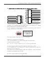
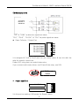
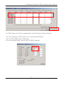
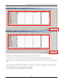
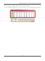
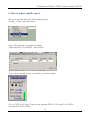
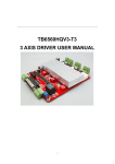
The Manual of Mach3, EMC2 Interface Board CM106 The Manual of Mach3, EMC2 Interface Board CM106 1. Outline This is a Mach3, EMC2 Interface Board. It is linked with Parallel Port attached in PC It was made that each signal of parallel port to be connected motor driver. Each input/output port in breakout board is connected with the driver or can be joined limit & home sensor and it offers Relay contact signal for speed control of spindle & exterior device. Unit mm 1 JI Robotics The Manual of Mach3, EMC2 Interface Board CM106 +24V DC Power P1.1 NO Contact GND P1.17 NO Contact P1.16 NO Contact P2.17 NO Contact Spindle Speed DC Voltage Select 0~10V/0~5V P2.16 NO Contact P2.14 NO Contact P1.14 NO Contact P2.1 Spindle Speed DC Voltage Output P1.2 X axis Pulse +24V DC Power P1.15 Input P2.15 Input GND P1.3 X axis DIR P1.4 Y axis Pulse +24V DC Power P1.10 Input P1.11 Input P1.12 Input P1.13 Input GND P1.5 Y axis DIR P1.6 Z axis Pulse P1.7 Z axis DIR +24V DC Power P2.10 Input P2.11 Input P2.12 Input P2.13 Input GND P1.8 A axis Pulse P1.9 A axis DIR P2.2 B axis Pulse VOC DC Power P2.6 OC Output P2.7 OC Output P2.8 OC Output P2.9 OC Output GND P2.3 B axis DIR P2.4 C axis Pulse VOC Power Select P2.5 C axis DIR 2 JI Robotics The Manual of Mach3, EMC2 Interface Board CM106 2. Detailed function Switch or Sensor Input Port. +24V DC Power P1.15 Input P2.15 Input GND +24V DC Power P1.10 Input P1.11 Input P1.12 Input P1.13 Input GND +24V DC Power P2.10 Input P2.11 Input P2.12 Input P2.13 Input GND There are total 10 connectors (5 for port1 / 5 for port2) as above picture, It has each 4 or 6 pins. 24V Pin here provides power of exterior sensor and can be joined to the sensor to be input by +24V If the sensor is the contact by type of switch, you can do not to use 24V Pin. Input signal here can connect “High” “Low” & “Switch Contact” The operation for each inputting can modify setting in port & pins in menu after checking it in Diagnostics(Alt-7) It can link with emergency stop button to halt the system in this port when the emergency and can connect other input button too. 3 JI Robotics The Manual of Mach3, EMC2 Interface Board CM106 Speed Control of spindle & Relay Port for controlling exterior device. P1.1 NO Contact P1.17 NO Contact P1.16 NO Contact P2.17 NO Contact P1.14 NO Contact P2.16 NO Contact P2.1 Spindle Speed DC Voltage Output P2.14 NO Contact This port outputs 0~5V or 0~10V DC voltage for speed control of spindle. In Mach3, it is outputted after the PWM signal is converted to DC voltage when speed control of spindle by PWM mode. For DC voltage can change speed of motor by connecting to servo driver or inverter. You use No. 1 Pin in Port2 Spindle Speed DC Voltage Select 0~10V/0~5V The output voltage is selected 0~5V or 0~10V range. Relay Port is comprised of COM & NO. “NO” is normal open so, it is open usually and if the relay works, it means that it is connected. No.1, 14, 16, 17 in Port 1 and No.14, 16, 17 in Port 2 are allocated. To extend exterior output, you should need an output control code. For an example, the 14 in Relay port P2 above is allotted by Pin No.14 in port2 and it is set Output #3. This output can use after assigning to M3, M7, or M8 but I show you another example to use making other M Code. M code is saved in Mach3-macros-Mach3Mill. 4 JI Robotics The Manual of Mach3, EMC2 Interface Board CM106 Open an note pad to create a new M code ActivateSignal(output3) Put down above and save as M12.m1s DeActivateSignal(output3) Put down above again and save as M13.m1s And if you spell M12 in MDI screen, the relay3 should be “On” If you spell M13, you can check it out that it should be “Off” MDI input window is in MDI(Alt-2) Port connecting to driver P1.2 X axis Pulse P1.3 X axis DIR This is the port to join the driver in each axis and is made by Pins above. This port can link with revolving axis as well as moving straightly in each axis and can do also speed control for by connecting to motor driver for spindle. For linking with driver, It applies +/- line driver and is the output 1pulse as DIR / PLS It is allotted 2~9 in port1 and 2~5 in port2 5 JI Robotics The Manual of Mach3, EMC2 Interface Board CM106 EX) Samsung servo Line Driver MC3487 or AM26LS31 “DIR” & “SIGN” as direction signal are same. “PLS”, “PULS”, “CLOCK”, & “CLK” as pulse signal are same. Open Collector / Output Port VOC DC Power P2.6 OC Output P2.7 OC Output P2.8 OC Output P2.9 OC Output GND It is assigned 6,7,8,9 in Port2 and can join motor driver & can link with the relay for exterior control too. Power VOC using here can select below pins. If you connect with motor driver, use 5V and if the relay, use 24V VOC Power Select Power Input Port +24V DC Power GND It is the port accepting +24V power for Board-driven. 6 JI Robotics The Manual of Mach3, EMC2 Interface Board CM106 If you don’t use Power for driver in exterior, it has about 80mA current consumption. 3. Mach3 / Run Screen 4. Mach3, Set-Up “Set Value” made here, is just an example. It can possible to set it variously and can do detailed modification. Menu / Config → Select Native Units→ Choose “ MM’s “ 7 JI Robotics The Manual of Mach3, EMC2 Interface Board CM106 Menu / Config → Set up in Port and Pins as below. Confirm Pin No. & Port No. exactly. **** Make sure to press “Apply” button before going on to each tap. If it is not, it isn’t saved. **** If you use A,B,C axis, Set up them and if you don’t want to, Remove “Enabled” 8 JI Robotics The Manual of Mach3, EMC2 Interface Board CM106 For both “Dir Low Active” and “Step Low Active” You should set after judging the direction well in each axis in CNC in view of surroundings your driver is working. And Voltage Output Pin for speed control of spindle is set No.17 This process can be differ depending on users and it has to be followed some efforts experiencing a few trial & error experiments. Set up X Home, Y Home & Z Home. 9 JI Robotics The Manual of Mach3, EMC2 Interface Board CM106 If use A,B,C axis, set it and if it is not, remove “Enable” “Set Value” can be much different because users could do “Home” or ‘Limit” Set up “EStop Pin” as above. In “ActiveLow“ case here, should apply after checking out whether your emergency stop button is “Active Low” or “Active High” For probe, it is allotted for Tool Zero Sensor in Z axis. 10 JI Robotics The Manual of Mach3, EMC2 Interface Board CM106 For OEM Trigger #1 & #2 are assigned for Cycle Start and Feed Hold button. The 1000 inputted in OEM Trigger #1 is Cycle Start OEM Code. 1001 of #2 is OEM Code in Feed Hold. For more detailed thing, hope to refer to MACH3 manual. 11 JI Robotics The Manual of Mach3, EMC2 Interface Board CM106 Enable 2~5 is the pin assigned by Open Collector Output. For Output #1, #2, #3, #4, & #5Pin are relay output port and set as above. In ActiveLow, should apply after thinking according to exterior device connected your CNC. If you want to use spindle & pump for cutting oil, remove “checking” above picture. If it is checked, it means that it does not use. To set speed control of spindle is as follows.. 12 JI Robotics The Manual of Mach3, EMC2 Interface Board CM106 5. Motor Tuning Menu / Config → choose “ Motor Tuning” Select “X axis” and set to be fit user’s equipment. For Velocity or Acceleration, it can alter adequately. ***** Make sure to press “Save Axis Setting” after inputting. 13 JI Robotics The Manual of Mach3, EMC2 Interface Board CM106 14 JI Robotics The Manual of Mach3, EMC2 Interface Board CM106 15 JI Robotics The Manual of Mach3, EMC2 Interface Board CM106 Menu / Config → Choose “Motor Homing” and set as below. For more detailed explanation as for each functions, refer to mach3 program manual. 16 JI Robotics The Manual of Mach3, EMC2 Interface Board CM106 6. How to adjust spindle speed Set up as follows after you finish setting above. Config → Click “Spindle Pulleys” Input “Max Speed” of spindle as below. If Max Speed is 20,000RPM , input 20000 If so, can do speed control of spindle in mach program. If it is S1000 on G code, It means the spindle RPM is 1000 and if it is S5000 It means the RPM is 5000 17 JI Robotics The Manual of Mach3, EMC2 Interface Board CM106 7. Further Information Allotted pin for Home & Limit Sensor is available in many ways. You can connect one pin together to Home & Limit sensor in each axis in CNC and the rest of pins can be allocated by switch input too setting up Probe Sensor or OEM Trigger. For more detailed, refer to MACH3 manual. ** If you have any questions or concerns, feel free to contact us anytime via facebook below. Go to Page : http://www.facebook.com/pages/JI-Robo-Cnc/102510056566519?ref=hl Pls..First, Click “ Like” and leave a comment [email protected] 18 JI Robotics