1
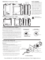
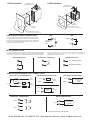
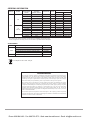
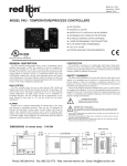
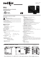
Drawing No. LP0951C
Released 05/14
PXU
Temperature/Process Controller
Installation Guide
C
UL
R
US LISTED
13RW
PROCESS CONTROL EQUIPMENT
See the Red Lion website for a complete
user manual.
CAUTION: Risk of electric shock.
When the power is on, DO NOT touch the AC terminals, an electric shock may
occur. Make sure the power is disconnected when you check the input power supply.
1. Prevent dust or metallic debris from falling into the controller and causing malfunctions. DO
NOT modify the controller.
2. The PXU is an open-type device. Make sure it is installed in an enclosure free of dust and
humidity in case of an electric shock.
3. Wait for one minute after the power is switched off to allow the unit to discharge. DO NOT touch
the internal wiring within this period of time.
SPECIFICATIONS
POWER:
Line Voltage Models:
100 to 240 VAC -20/+8 %, 50/60 Hz, 5 VA
Low Voltage Models:
DC Power: 24 VDC, ±10%, 5 W
INPUT CAPABILITIES:
Thermocouple Inputs:
Types: T, E, J, K, R, S, B, N, L, U, and TXK
RTD Inputs:
Type: 2 or 3 wire, 2 wire can be compensated for lead wire resistance
Excitation: 180 µA typical
Input Type:
100 Ω Pt alpha = .00385
120 Ω Nickel alpha = .00672
Process Input Ranges:
0-5 VDC
0-20 mA
0-10 VDC
4-20 mA
100 Ω Pt alpha = .00392
50 Ω Copper alpha = .00428
0-50 mV
USER INPUT (Optional):
Contact/NPN Open Collector Input:
ON Resistance 1 KΩ max.
OFF Resistance 100 KΩ min.
Response Time: 1 sec max
Functions: Programmable
OUTPUT:
CONTROL RELAY OUTPUTS (OUT1/OUT2):
Type: Form A
Contact Rating: 5 A @ 250 VAC
Contact Isolation to all I/O: 2300 VAC for 1 min.
CONTROL SSR DRIVE OUTPUT (OUT1):
Rating: 12 VDC ± 10% @ 40 mA max.
CONTROL OUTPUT (OUT1) Analog Models:
Analog Types: 4 to 20 mA or 0 to 10 VDC
Isolation To Sensor & Communication Common: 500 VDC for 1 min.
Compliance: 10 VDC: 1 KΩ load min., 20 mA: 500 Ω load max.
ALARMS: 2 relay alarm outputs.
Type: Form A or Form C, model and alarm dependent
Contact Rating: 3 A @ 250 VAC
ENVIRONMENTAL CONDITIONS:
Operating Temperature Range: 0 to 50 °C
Storage Temperature Range: -20 to 65 °C
Vibration Resistance: Operational 10 to 55 Hz, 1 g
Shock Resistance: Operational 30 g
Operating and Storage Humidity: 80% max relative humidity (noncondensing) from 0°C to 50°C
Altitude: Up to 2000 meters
CERTIFICATIONS AND COMPLIANCES:
CE Approved
EN 61326-1 Immunity to Industrial Locations
Emission CISPR 11 Class A
EN 61010-1
RoHS Compliant
UL Listed: File #E179259
IP65 Enclosure rating (Face only)
CONNECTIONS: Wire-clamping screw terminals
CONSTRUCTION: Black plastic alloy case and panel latch. Black plastic
textured bezel with transparent display window. Controller meets IP65
requirements for indoor use when properly installed. Installation Category II,
Pollution Degree 2.
WEIGHT:
1/4 DIN: 11.0 oz (312 g)
1/8 DIN: 7.8 oz (221 g)
1/16 DIN: 5.3 oz (150 g)
DIMENSIONS In inches (mm) - 1/16 DIN
PANEL CUT-OUT
1.89
(48.0)
0.26
(6.70)
3.14 (79.70)
1.77
(45.0)
0.31
(7.80)
0.47 (11.88)
2
1.89
(48.0)
7
1
13
8
14
0.83 (21.0)
3
15
9
16
4
17
10
1.77
(45.0)
18
5
11
6
12
Phone: 800.894.0412 - Fax: 888.723.4773 - Web: www.the-red-lion.net - Email: [email protected]
SAFETY SUMMARY
DIMENSIONS In inches (mm) - 1/8 DIN
1.89
(48.0)
0.45
(11.4)
PANEL CUT-OUT
1.76
(44.5)
2.82 (71.5)
3.77
(95.8)
3.60
(91.5)
F1
D
F2
1
13
2
14
3
15
4
16
5
17
6
18
7
19
8
20
9
21
10
22
11
23
12
24
3.60
(91.5)
P
DIMENSIONS In inches (mm) - 1/4 DIN
3.77 (95.8)
0.45
(11.4)
CAUTION: Risk of Danger.
Read complete instructions prior to
installation and operation of the unit.
PANEL CUT-OUT
3.58 (91.0)
2.82 (71.5)
3.58
(91.0)
3.77
(95.8)
All safety related regulations, local
codes and instructions that appear in the
manual or on equipment must be observed
to ensure personal safety and to prevent
damage to either the instrument or
equipment connected to it. If equipment is
used in a manner not specified by the
manufacturer, the protection provided by
the equipment may be impaired.
Do not use the controller to directly
command motors, valves, or other
actuators not equipped with safeguards. To
do so can be potentially harmful to persons
or equipment in the event of a fault to the
controller. If redundant safeguards are not
in place, an independent and redundant
temperature limit indicator with alarm
outputs is strongly recommended.
1
25
13
2
26
14
3
27
15
4
28
16
5
29
17
6
30
18
7
31
19
8
32
20
9
33
21
10
34
22
11
35
23
12
36
24
3.58
(91.0)
SETTING THE CURRENT INPUT JUMPER
When Input Type is selected as one of the two current input types (0-20 or
4-20), the current input jumper must be installed. The current input jumper is
factory set for Temperature and Voltage input types. To change the jumper to
configure the input for a current input type, the inside of the unit must be
accessed and the jumper position changed.
To access the jumper, locate the two latches located on top and bottom of the
front of the unit. Starting with the top latch, insert a small flat-blade screwdriver
between the case latch and bezel while using your thumb to push out on the
bezel until the latch is disengaged. Repeat this process with the bottom latch.
After the latches are disengaged, using the flat-blade screwdriver, gently pry out
on the bezel in several areas until the unit releases from the case.
Look for the Current Input Jumper which will be located close to the pc board
area that connects to the input terminals. If a current input type is desired,
position the jumper across both pins. If input type is anything other than a
current input, position the jumper on only one pin.
Thermocouple, RTD
or Voltage Input
Current Input
(4-20 mA or 0-20 mA)
JUMPER
JP8
PIN HEADER
JUMPER
JP8
PIN HEADER
FACTORY SETTING
INSTALLING THE CONTROLLER
The controller is designed to be mounted into an enclosed panel. The unit
must be inserted in the case during installation of the controller.
Instructions:
1. Prepare the panel cutout to the proper dimensions.
2. Assemble the mounting clip by inserting the nut into the slot and then insert
the screw and thread through the nut as shown (See drawing)
3. Slide the panel gasket over the rear of the controller, seating it against the lip
at the front of the case.
4. Insert the controller into the panel cutout. While holding the controller
in place, install the panel latch(es) and then slide it to the farthest
PANEL LATCH
forward slot possible.
(SUPPLIED W/UNIT)
5. To achieve a proper seal, tighten the panel latch screws evenly until the
controller is snug in the panel, torquing the screws to 13.9 to 20.8 oz-in
(9.8 to 14.7 N-cm). Overtightening can result in distortion of the
controller, and reduce the effectiveness of the seal.
Note: The installation location of the controller is important. Be sure to
keep it away from heat sources (ovens, furnaces, etc.) and away from
direct contact with caustic vapors, oils, steam, or any other process
by-products in which exposure may affect proper operation.
7
8
9
10
11
12
PANEL GASKET
EXISTING PANEL CUT-OUT
1/16 DIN
1.77” (45.0 mm) X 1.77” (45.0 mm)
1/16 DIN Installation
Phone: 800.894.0412 - Fax: 888.723.4773 - Web: www.the-red-lion.net - Email: [email protected]
1/8 DIN Installation
1/4 DIN Installation
(2) PANEL LATCH
(SUPPLIED W/UNIT)
(4) PANEL LATCH
(SUPPLIED W/UNIT)
13
14
15
16
17
18
19
20
21
22
23
24
PANEL
GASKET
PANEL
GASKET
EXISTING PANEL CUT-OUT
3.58" (91.0 mm) X 3.58" (91.0 mm)
EXISTING PANEL CUT-OUT
1.76" (44.5 mm) X 3.60" (91.5 mm)
VAC
L
1
CONTROLLER POWER CONNECTIONS
For best results, the power should be relatively “clean” and within
the specified limits. Drawing power from heavily loaded circuits or
from circuits that also power loads that cycle on and off should be
avoided. It is recommended that power supplied to the controller be
protected by a fuse or circuit breaker.
VDC
DC 24V
1
0V
2
AC 100-240V
50/60 Hz
5VA
+
_
2
N
INPUT CONNECTIONS
lead wire compensation. If a sense wire is not used, then use a jumper. A
temperature offset error will exist. The error may be compensated by
programming a temperature offset.
For two wire RTDs, install a copper sense lead of the same gauge and length
as the RTD leads. Attach one end of the wire at the probe and the other end to
input common terminal. This is the preferred method as it provides complete
RTD and Resistance
Thermocouple and Millivolt
Voltage and Current
10
11
TC+
11
DC+ VOLTAGE/CURRENT
11
12
TC-
12
DC- VOLTAGE/CURRENT
12
CONTROL AND ALARM OUTPUT CONNECTIONS
Alarm 1 and 2 * (1/16 DIN Shown)
COMM
AL 2
NO
AC/DC
Power (-)
NO
LOAD
NO (+)
AC/DC
Power (+)
AC/DC
Power
COMM (-)
COMM (-)
IN -
ANALOG INPUT
CONTROL
DEVICE
+
AC
SSR
POWER
- UNIT
AC
AC Power
RS 485 CONNECTIONS *
+
User 1
D-
-
RS-485
+
+
User 2
IN +
OP1 Output Control Logic/SSR *
NO (+)
USER INPUT CONNECTIONS *
OP1 Output Control Analog *
NO (+)
LOAD
COMM (-)
LOAD
AL 1
OP1/OP2 Output Control Relay *
RS485
RECEIVING
DEVICE
D+
-
* See unit label for terminal identification.
Phone: 800.894.0412 - Fax: 888.723.4773 - Web: www.the-red-lion.net - Email: [email protected]
ORDERING INFORMATION
MODEL NO.
DIN SIZE
1/16
PXU
1/8
(vertical)
1/4
MAIN CONTROL
OUTPUT 1
SECONDARY
CONTROL OUTPUT 2
PART NUMBERS
USER INPUT(S)
RS 485
100 to 240 VAC
24 VDC
Relay
-
-
-
PXU10020
PXU100B0
Relay
Relay
2
Yes
PXU11A20
PXU11AB0
Logic/SSR
-
-
-
PXU20020
PXU200B0
Logic/SSR
Relay
2
Yes
PXU21A20
PXU21AB0
4-20 mA
-
-
-
PXU30020
PXU300B0
4-20 mA
Relay
2
Yes
PXU31A20
PXU31AB0
Relay
-
-
-
PXU10030
PXU100C0
Relay
Relay
2
Yes
PXU11A30
PXU11AC0
Logic/SSR
-
-
-
PXU20030
PXU200C0
Logic/SSR
Relay
2
Yes
PXU21A30
PXU21AC0
PXU31AC0
4-20 mA
Relay
2
Yes
PXU31A30
Relay
Relay
2
Yes
PXU11A50
PXU11AE0
4-20 mA
Relay
2
Yes
PXU31A50
PXU31AE0
Only stocked part numbers are listed. Contact factory for availability of non-stock models.
In order to program the unit using Crimson, the unit must be purchased with the 485 option.
ACCESSORIES
MODEL NO.
DESCRIPTION
PART NUMBERS
External SSR Power Unit (for Logic/SSR models)
RLY
SFCRD
1
RLY50000
25 A Single Phase Din Rail Mount Solid State Relay
RLY60000
40 A Single Phase Din Rail Mount Solid State Relay
RLY6A000
Three Phase Din Rail Mount Solid State Relay
RLY70000
Crimson PC Configuration Software
SFCRD200
Crimson software is a free download from Red Lion website.
Do not dispose of unit in trash - Recycle
LIMITED WARRANTY
The Company warrants the products it manufactures against defects in materials and workmanship for a
period limited to two years from the date of shipment, provided the products have been stored, handled,
installed, and used under proper conditions. The Company’s liability under this limited warranty shall
extend only to the repair or replacement of a defective product, at The Company’s option. The Company
disclaims all liability for any affirmation, promise or representation with respect to the products.
The customer agrees to hold Red Lion Controls harmless from, defend, and indemnify RLC against
damages, claims, and expenses arising out of subsequent sales of RLC products or products containing
components manufactured by RLC and based upon personal injuries, deaths, property damage, lost profits,
and other matters which Buyer, its employees, or sub-contractors are or may be to any extent liable,
including without limitation penalties imposed by the Consumer Product Safety Act (P.L. 92-573) and
liability imposed upon any person pursuant to the Magnuson-Moss Warranty Act (P.L. 93-637), as now in
effect or as amended hereafter.
No warranties expressed or implied are created with respect to The Company’s products except those
expressly contained herein. The Customer acknowledges the disclaimers and limitations contained herein
and relies on no other warranties or affirmations.
Phone: 800.894.0412 - Fax: 888.723.4773 - Web: www.the-red-lion.net - Email: [email protected]