1
IA31 Motherboard
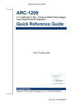
Ultra slim SBC w/ Intel®ATOM N270
1.6GHz Processor, VGA, LCD, Giga
Ethernet, and Mini-PCI interface.
USER MANUAL Version 1.0
FCC Statement
This device complies with part 15 FCC rules. Operation is subject to
the following two conditions:
This device may not cause harmful interference.
This device must accept any interference received including
interference that may cause undesired operation.
This equipment has been tested and found to comply with the limits for a class "a"
digital device, pursuant to part 15 of the FCC rules. These limits are designed to
provide reasonable protection against harmful interference when the equipment is
operated in a commercial environment. This equipment generates, uses, and can
radiate radio frequency energy and, if not installed and used in accordance with the
instruction manual, may cause harmful interference to radio communications.
Operation of this equipment in a residential area is likely to cause harmful
interference in which case the user will be required to correct the interference at him
own expense.
IA31 Motherboard User Manual
II
Copyright Notice
ALL RIGHTS RESERVED. No part of this document may be reproduced, copied,
translated, or transmitted in any form or by any means, electronic or mechanical, for
any purpose, without the prior written permission of the original manufacturer.
Trademark Acknowledgement
Brand and product names are trademarks or registered trademarks of their respective
owners.
Disclaimer
We reserve the right to make changes, without notice, to any product, including
circuits and/or software described or contained in this manual in order to improve
design and/or performance. We assume no responsibility or liability for the use of the
described product(s), conveys no license or title under any patent, copyright, or masks
work rights to these products, and makes no representations or warranties that these
products are free from patent, copyright, or mask work right infringement, unless
otherwise specified. Applications that are described in this manual are for illustration
purposes only. We make no representation or warranty that such application will be
suitable for the specified use without further testing or modification.
Warranty
We warrant that each of its products will be free from material and workmanship
defects for a period of one year from the invoice date. If the customer discovers a
defect, We will, at its option, repair or replace the defective product at no charge to
the customer, provided it is returned during the warranty period of one year, with
transportation charges prepaid. The returned product must be properly packaged in its
original packaging to obtain warranty service.
If the serial number and the product shipping data differ by over 30 days, the
in-warranty service will be made according to the shipping date. In the serial numbers
the third and fourth two digits give the year of manufacture, and the fifth digit means
the month (e. g., with A for October, B for November and C for December).
For example, the serial number 1W07Axxxxxxxx means October of year 2007.
IA31 Motherboard User Manual
III
Packing List
Before using this Motherboard, please make sure that all the items listed below are
present in your package:
IA31 Motherboard
IA31 SBC User Manual
HDD IDE Cable
User’s Manual & Driver CD
If any of these items are missing or damaged, contact your distributor or sales
representative immediately.
Customer Service
We provide service guide for any problem as follow steps:First, visit the website at to
find the update information about the product. Second, contact with your distributor,
sales representative, or our customer service center for technical support if you need
additional assistance. You may have the following information ready before you call:
Product serial number
Peripheral attachments
Software (OS, version, application software, etc.)
Description of complete problem
The exact wording of any error messages
In addition, free technical support is available from our engineers every business day.
We are always ready to give advice on application requirements or specific
information on the installation and operation of any of our products. Please do not
hesitate to call or e-mail us.
IA31 Motherboard User Manual
IV
Safety Precautions
Warning!
Always completely disconnect the power cord from your chassis
whenever you work with the hardware. Do not make connections
while the power is on. Sensitive electronic components can be
damaged by sudden power surges. Only experienced electronic
personnel should open the PC chassis.
Caution!
Always ground yourself to remove any static charge before
touching the CPU card. Modern electronic devices are very
sensitive to static electric charges. As a safety precaution, use a
grounding wrist strap at all times. Place all electronic components
in a static-dissipative surface or static-shielded bag when they are
not in the chassis.
7
IA31 Motherboard User Manual
V
Safety and Warranty
1.
2.
3.
4.
5.
6.
7.
8.
9.
10.
11.
12.
13.
14.
15.
Please read these safety instructions carefully.
Please keep this user's manual for later reference.
Please disconnect this equipment from any AC outlet before cleaning. Do not use
liquid or spray detergents for cleaning. Use a damp cloth.
For pluggable equipment, the power outlet must be installed near the equipment
and must be easily accessible.
Keep this equipment away from humidity.
Put this equipment on a reliable surface during installation. Dropping it or letting
it fall could cause damage.
The openings on the enclosure are for air convection. Protect the equipment from
overheating. DO NOT COVER THE OPENINGS.
Make sure the voltage of the power source is correct before connecting the
equipment to the power outlet.
Position the power cord so that people cannot step on it. Do not place anything
over the power cord.
All cautions and warnings on the equipment should be noted.
If the equipment is not used for a long time, disconnect it from the power source
to avoid damage by transient over-voltage.
Never pour any liquid into an opening. This could cause fire or electrical shock.
Never open the equipment. For safety reasons, only qualified service personnel
should open the equipment.
If any of the following situations arises, get the equipment checked by service
personnel:
A. The power cord or plug is damaged.
B. Liquid has penetrated into the equipment.
C. The equipment has been exposed to moisture.
D. The equipment does not work well, or you cannot get it to work according to
the user’s manual.
E. The equipment has been dropped and damaged.
F. The equipment has obvious signs of breakage.
Do not leave this equipment in an uncontrolled environment where the storage
temperature is below -20° C (-4°F) or above 60° C (140° F). It may damage the
equipment.
IA31 Motherboard User Manual
VI
Revision History
Version
1.0
Date
2009.03.25 IA31 Motherboard User Manual
Note
Initial Draft
VII
Author
Aladin Huang
Contents
CHAPTER 1
GENERAL INFORMATION.......................................1
1.1
1.2
1.3
1.4
INTRODUCTION ...............................................................................1
FEATURE .........................................................................................1
MOTHERBOARD SPECIFICATIONS ....................................................2
FUNCTION BLOCK ...........................................................................3
1.5
BOARD DIMENSIONS........................................................................4
CHAPTER 2
INSTALLATIONS.........................................................6
2.1
MEMORY MODULE(DIMM)INSTALLATION ................................6
2.2
2.3
I/O EQUIPMENT INSTALLATION .......................................................7
JUMPERS AND CONNECTORS ...........................................................8
2.4
2.5
JUMPER SETTING.............................................................................9
CONNECTORS AND PIN ASSIGNMENT ............................................ 11
CHAPTER 3
GRAPHIC DRIVER INSTALLATION 錯誤! 尚未定
義書籤。
3.1
3.2
CHAPTER 4
4.1
STANDARD CMOS FEATURE ...................... 錯誤!
尚未定義書籤。
。
錯誤 尚未定義書籤
PANEL RESOLUTION SETTING ..................... 錯誤!
錯誤 尚未定義書籤。
尚未定義書籤。
CHIPSET DRIVER INSTALLATION .....................28
STANDARD CMOS FEATURES ........................................................28
CHAPTER 5 ETHERNET DRIVER INSTALLATION..................33
5.1
5.1
CHAPTER 6
INTRODUCTION ..............................................................................33
INSTALLATION OF ETHERNET DRIVER ...........................................34
AUDIO DRIVER INSTALLATION..........................38
6.1
INTRODUCTION ..............................................................................38
6.2
INSTALLATION OF AUDIO DRIVER .................................................38
CHAPTER 7
7.1
7.2
7.3
AMI BIOS SETUP ......................................................41
STARTING SETUP ...........................................................................41
SYSTEM OVERVIEW.......................................................................42
ADVANCED SETTING ....................................................................43
NOTE1: DIGITAL I/O SAMPLE CODE.............................................75
IA31 Motherboard User Manual
VIII
CHAPTER
General Information
1
This chapter includes IA31 Motherboard background
information.
Sections include:
Introduction
Feature
Motherboard Specification
Function Block
Board Dimensions
IA31 Motherboard User Manual
1
Chapter 1
1.1
General Information
Introduction
IA31 SBC integrates Intel 945GSE North Bridge and Intel ICH7M South Bridge
which are designed for use with Intel’s mobile platform. Intel’s 945GSE platform
delivers the performance and high scalability cutting-edge embedded computing
application.
In peripheral connectivity, IA31 SBC with Mini-PCI I/O ports, Giga LAN, two
SATA connectors, and four Hi-Speed USB connectors.
Thus, IA31 SBC is designed to satisfy most of the applications in the industrial
computer market, such as Gaming, POS, KIOSK, Industrial Automation, and
Programmable Control System. It is a compact design to meet the demanding
performance requirements of today’s business and industrial applications.
1.2
Feature
Supports Intel® Atom N270 1.6GHz processors
System memory up to 2GB DDR2 400/533, 1x SO-DIMM
Integrated Intel 945GSE + ICH7M Chipset
Intel® GMA950 graphic engine Integrated 224MB shared supports VGA
Gigabit Ethernet
1 x Mini PCI, 4 x COM, 4 x USB2.0, 1 x CF
2 x SATA, 4DI/ 4DO
IA31 Motherboard User Manual
1
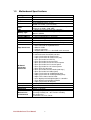
1.3
Motherboard Specifications
CPU Type
CPU FSB
Chipset
BIOS
VGA
LVDS
LAN
Memory Type
LPC I/O
Keyboard/Mouse
IDE Interface
Sound
USB
Edge Connectors
On Board
Pin-Header
Connectors
Power Connector
Expansion Slots
Form Factor
Dimensions
Mechanical &
environmental
Intel® Atom N270 1.6GHz Processor
533 MHz
Intel 945GSE / ICH7M
AMI 4Mbit Flash
Intel® GMA950 Graphic engine
224MB shared with system memory
Intel® 82945GSE built in single- or Dual-channel panel
support up to 1600 x 1200, 24bit
1 x Giga LAN ( Realtek RTL8111B Controller )
1 x DDR2 DIMM socket, supports up to 2GB DDR2
400/533 SDRAM
Winbond W83627EHG
1 x PS/2 Keyboard/Mouse connectors
Dual channels; supports Ultra DMA 33/66/100
Realtek ALC655 (Line-in, Line-out, Mic in)
4 ports, USB 2.0 (2 x USB Connector, 2 x USB pin-header )
1 x +12V DC-IN Jack
1 x PS/2 connector for keyboard/mouse
1 x DB9 for COM3
1 x VGA out connector
1 x Gigabit LAN RJ-45 + 1 x dual USB stack connector
1 x 44 pins box-header
2 x SATA connector for SATAI/II 3.0 Gb/s
1 x 13pins pin-header for Front Panel2
1 x 10pins pin-header for Front Panel1(2x5)
1 x 3pins pin-header for CPU Fan
1 x 3pins pin-header for System FAN
1 x 8pins pin-header for 5V/12V external power
1 x 2pins pin-header for 5V external power
1 x 2pins pin-header for 12V external power
1 x 4pins ATX 12V connector
2 x 2pins pin-header for Front Audio (with Amp.)
1 x 8pins pin-header for USB 3/4(2x4)
1 x 10pins pin-header for COM3(RS232)(2x5)
1 x 20pins pin-header for COM1/2(RS232)(2x10)
1 x 40pins DF13 Connector for LVDS
1 x 3pins digital panel backlight brightness controller
1 x 7pins digital panel backlight controller
1 x 10pins pin-header for DIO(2x5)
Input: 4-pin ATX 12V Power input
1 x Mini-PCI
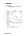
Ultra Slim Board
146mm x 126.6mm
Operating temperature: 0 deg. C to 60 deg. C
Operating Humidity: 30 ~ 90% Relative humidity,
non-condensing
Certification: CE, FCC, RoHS
IA31 Motherboard User Manual
2
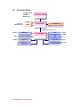
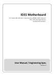
1.4
Function Block
ATOM N270
1.6GHz
Processor
Atom N270 1.6GHz
FSB 400
1600*1200
24bit/Dual CH
CRT
Intel 945GSE
LVDS
SO-DIMM x 1
DDR2 533/400 Max.2GB
66MHz Hub Interface 1.5
ATA100
3GB/s
33MHz
1 x IDE Host
Intel ICH7M
SATA II 1, SATAII 2
Mini PCI
1GB/s
USB
480MB/s
Audio
RTL ALC655
Super IO
W83267EHG
Secondary IO Fintek 81216D
SPI ROM
IA31 Motherboard User Manual
LAN
3
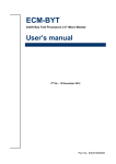
1.5
Board dimensions
IA31 Motherboard User Manual
4
CHAPTER
Installations
2
This chapter provides information on how to use the
jumps and connectors on IA31 Motherboard.
The Sections include:
Memory Module Installation
I / O Equipment Installation
Setting the Jumpers
Connectors on IA31 Motherboard
IA31 Motherboard User Manual
5
Chapter 2
Installations
2.1 Memory Module(
(DIMM)
)Installation
IA31 motherboard supports one 200-pin SODIMM slot. The socket supports up to
2GB DDR2 400/533 SDRAM.
Step.2. Press downwards on SODIMM until the retaining clips at both ends fully snap
back in place and the SODIMM is properly seated.
Caution!
The SODIMM only fits in one correct orientation. It will cause
permanent damage to the development board and the SODIMM if
the SODIMM is forced into the slot at the incorrect orientation.
IA31 Motherboard User Manual
6
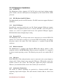
2.2 I/O Equipment Installation
2.2.1 12V DC-IN
The Motherboard allows plugging 12V DC-IN jack on the board without another
power module converter under powered consumption by Intel Atom N270 1.6GHz
processor.
2.2.2 PS/2 Keyboard and PS/2 Mouse
The Motherboard provides one PS/2 interface. The PS/2 connector supports Keyboard
and Mouse.
2.2.3 Serial COM ports
Four RS-232 connectors build in the rear I/O. Fourth optional COM ports support
RS-232. When an optional touch-screen is ordered with PPC, serial com port can
connect to a serial or an optional touch-screen. One optional COM port supports
RS232/422/485 choice through jumper setting.
2.2.4 External VGA
The Motherboard has one VGA port that can be connected to an external CRT/ LCD
monitor. Use VGA cable to connect to an external CRT / LCD monitor, and connect
the power cable to the outlet. The VGA connector is a standard 15-pin D-SUB
connector.
2.2.5 Ethernet interface
The Motherboard is equipped with Realtek RTL8111B chipsets which is fully
compliant with the 10/100/1000 Mbps Ethernet protocol compatible. It is supported
by major network operating systems. The Ethernet ports provide two standard RJ-45
jacks.
2.2.6 USB ports
Four USB devices (Two with pin headers) may be connected to the system though an
adapter cable. Various adapters may come with USB ports. USB usually connect the
external system to the system. The USB ports support hot plug-in connection.
Whatever, you should install the device driver before you use the device.
2.2.7 Audio Jack ( Pin-header)
The Audio 5.1 channel capabilities are provided by a Realtek ALC655 chipset
supporting digital audio outputs. The audio interface includes Mic-in,: line-in and
line-out.
IA31 Motherboard User Manual
7
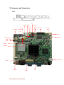
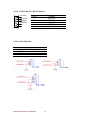
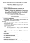
2.3 Jumpers and Connectors
TOP
JP6
CON17 CON16
CON18
SATA2
CON6
NB Fan1
CON14 CON12
Panel 2
SATA1
Panel 1
CPU Fan1
CON19
USB1
IDE1
CON11
CON10
ATX12V1
CON3
CON20
JP7
CON1
IA31 Motherboard User Manual
8
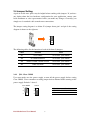
2.4 Jumper Setting
A pair of needle-nose pliers may be helpful when working with jumpers. If you have
any doubts about the best hardware configuration for your application, contact your
local distributor or sales representative before you make any changes. Generally, you
simply need a standard cable to make most connections.
The jumper setting diagram is as below. If a jumper shorts pin 1 and pin 2, the setting
diagram is shown as the right one.
1
2
3
The following tables list the function of each of the board's jumpers.
Label
Function
Note
JP1
Clear CMOS
3x1 header , pitch 2.0mm
JP2
CF CARD PRIORITY
3x1 header , pitch 2.0mm
JP6
RS232 / RS422 / RS485 Selector
2x3 header , pitch 2.0mm
JP7
LVDS VOLTAGE
2x3 header , pitch 2.0mm
2.4.1 JP1: Clear CMOS
User must make sure the power supply to turn off the power supply before setting
Clear CMOS. Users remember to setting jumper back to Normal before turning on the
power supply. Default: 2 short 3.
Clear CMOS
Normal
1
1
2
2
3
3
IA31 Motherboard User Manual
Pin No.
1 Short 2
2 Short 3
9
Functions
Clear CMOS
Normal
2.4.2 JP2 : CF Card Priority
JP901 can be configured to operate CF Card Priority in Master/Slave mode.
Master
Slave
1
1
2
2
3
3
Pin No.
1 Short 2
2 Short 3
Functions
Master
Slave
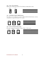
2.4.3 JP6: RS232 / RS422 / RS485 Selector
The jumper can be configured to operate COM2 in RS-232/422/485 mode. And the
setting must be cooperated with the 2.4.3 settings.
RS232
RS422
RS485
1
2
1
2
1
2
3
4
3
4
3
4
5
6
5
6
5
6
Pin No.
1 Short 2
3 Short 4
5 Short 6
Functions
RS232
RS422
RS485
2.4.4 JP7 : LCD Panel Voltage Select
JP7 can be configured to operate in 3.3Volts / 5Volts / 12Volts mode.
3.3Volts
5Volts
12Volts
1
2
1
2
1
2
3
4
3
4
3
4
5
6
5
6
5
6
IA31 Motherboard User Manual
Pin No.
1 Short 2
3 Short 4
5 Short 6
10
Functions
3.3Volts Selected
5Volts Selected
12Volts Selected
2.5 Connectors and Pin Assignment
The table below lists the function of each of the board’s connectors.
Label
Function
Note
CON1
LVDS LCD Output Connector
DF13-40DP-1.25V
CON20
Digital Panel Backlight Brightness Control
3x1 header, pitch 2.54mm
CON3
Digital Panel Backlight Inverter Power
7x1 header, pitch 2.54mm
PSKBM1
PS2 Keyboard/Mouse Connector
Mini-DIN
VGA
VGA Output
15pin VGA
CON12(Right)
COM1 for RS232
2x5 header
CON12(Left)
COM2 for RS232
2x5 header
CON14
COM2 for RS422/485
1x5 header
J8
Audio Jack
3 Audio I/O
IDE1
IDE Connector
44Pin IDE Conn.
USB1
USB PIN HEADER
4x2 Pin Header, pitch
2.0mm
NB_FAN1
FAN CONNECTOR
3x1 Pin Header
CPU_FAN1
FAN CONNECTOR
3x1 Pin Header
PANEL1
System Function Connector
5x2 header ,pitch 2.0mm
PANEL2
System Function Connector
1x13 Pin Headers
CON10
12V External Power
2x1 header, pitch 2.0mm
CON11
5V External Power
2x1 header, pitch 2.0mm
CON19
12V/5V External Power
4x2 header ,pitch 2.54mm
ATX 12V 1
12V DC Jack
4 Pin Jack
CON6
CON16
Digital I/O
COM3 for RS232
2x5 Pin header
2x5 header
IA31 Motherboard User Manual
11
2.5.1
2.5.2
CON1: LVDS Connector
Pin Number
Signal Name
Pin Number
Signal Name
1
LCDVDD
2
LVDS_LTX0-
3
LCDVDD
4
LVDS_LTX0+
5
LCDVDD
6
LVDS_LTX1-
7
GND
8
LVDS_LTX1+
9
GND
10
LVDS_LTX2-
11
GND
12
LVDS_LTX2+
13
GND
14
LVDS_LCLK-
15
GND
16
LCDS_LCLK
17
GND
18
LVDS_LTX3-
19
GND
20
LVDS_LTX3+
21
GND
22
LVDS_UTX0-
23
GND
24
LVDS_UTX0+
25
GND
26
LVDS_UTX1-
27
GND
28
LVDS_UTX1+
29
GND
30
LVDS_UTX2-
31
GND
32
LVDS_UTX2+
33
GND
34
LVDS_UCLK-
35
GND
36
LVDS_UCLK
37
GND
38
LVDS_UTX3-
39
GND
40
LVDS_UTX3+
CON20: Digital Panel Backlight Brightness Control
Pin No.
1
2
3
IA31 Motherboard User Manual
SYMBOL
VCC
Black Light Control
GND
12
2.5.3
2.5.4
CON3: Digital Panel Backlight Inverter Power
Pin Number
Signal Name
1
+12V
2
+12V
3
+12V
4
GND
5
Black Light Control
6
GND
7
Black Light EN 5V
PSKBM1: PS2 Keyboard/Mouse Connector
Signal Name
Keyboard
Mouse
Signal Name
Keyboard data
1
1
Mouse data
N.C.
2
2
N.C.
GND
3
3
GND
5V
4
4
5V
Keyboard clock
5
5
Mouse clock
N.C.
6
6
N.C.
IA31 Motherboard User Manual
13
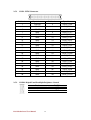
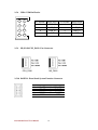
2.5.5 CON12: D-SUB Dual Output
CON12 is connecter for COM1 and COM2. COM1 is from pin 11 pin to pin 20),
COM2 is from pin 1 to pin10.
2.5.6
Pin No.
SYMBOL
Pin No.
SYMBOL
20
GND
19
GND
18
NRI1A
17
NDTR1A
16
NCTS1A
15
NTXD1A
14
NRTS1A
13
NRXD1A
12
NDSR1A
11
NDCD1A
10
GND
9
GND
8
NRIA
7
NDTRA
6
NCTSA
5
NTXDA
4
NRTSA
3
NRXDA
2
NDSRA
1
NDCDA
CON16: D-SUB Dual Output
The CON16 is COM3 port, support standard RS-232.
2
4
6
8
10
1
3
5
7
9
Pin
2
4
6
8
10
IA31 Motherboard User Manual
SYMBOL
NDSR2
NRTS2
NCTS2
NRI2
GND
14
Pin
1
3
5
7
9
SYMBOL
NDCD2
NSIN2
NSOUT2
NDTR1A
GND
2.5.7
1
IDE1: IDE Connector
2
44
Pin No.
1
3
5
7
9
11
13
15
17
19
21
23
25
27
29
31
33
35
37
39
41
43
SYMBOL
RESET
DD7
DD6
DD5
DD4
DD3
DD2
DD1
DD0
GND1
DREQ
DIOW#
DIOR#
IO_RDYD
DACK#
IRQ
DA1
DA0
DCS#1
DASP#
+5V1
GND
IA31 Motherboard User Manual
Pin No.
2
4
6
8
10
12
14
16
18
20
22
24
26
28
30
32
34
36
38
40
42
44
15
SYMBOL
GND3
DD8
DD9
DD10
DD11
DD12
DD13
DD14
DD15
NC
GND4
GND5
GND6
CSEL
GND7
IOCS16#
CBL_ID#
DA2
DCS#3
GND8
+5V2
NC
2.5.8
USB1: USB Pin Header
2
4
2.5.9
1
Pin Number
Signal Name
Pin Number
Signal Name
2
USBVCC
1
USBVCC
4
USB_P-
3
USB_P-
6
USB_P+
5
USB_P+
8
GND
7
GND
3
6
5
8
7
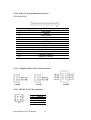
NB_FAN1/CPU_FAN1: Fan Connector
CPU_FAN1
NB_FAN1
2.5.10 PANEL1: Front Panel System Function Connector
Pin
2
4
6
8
10
SYMBOL
HD_LED+
HD_LEDRT_BT1
RT_BT2
5VSB
IA31 Motherboard User Manual
Pin
1
3
5
7
9
16
SYMBOL
PW_LED+
PW_LEDPW_BT1
PW_BT2
RSEV
2.5.11 Panel L2: System Function Connector
JST-B13B-PH-KL
Pin No.
1
2
3
4
5
6
7
8
9
10*
11*
12*
13*
SYMBOL
PWR Button
Ground
Reset Button
HD Led
5V
HD LED#
PWR LED
5V
Ground
Volume Control +
Volume Control Brightness Control +
Brightness Control -
*Not Default Setting
2.5.12 CON10/CON11/CON19: External Power
CON10
CON11
CON19
2.5.13 ATX12V 1: 12V DC Connector
Pin
1
2
3
4
IA31 Motherboard User Manual
SYMBOL
Ground
Ground
+12V
+12V
17
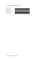
2.5.14 CON6: Digital I/O Connector
2
4
6
8
10
1
3
5
7
9
Pin
2
4
6
8
10
IA31 Motherboard User Manual
SYMBOL
Vcc
Out1
Out0
IN1
IN0
Pin
1
3
5
7
9
18
SYMBOL
GND
Out3
Out2
IN3
IN2
2.5.15 CON14: RS-422 / RS-485 Header
1
422 RX2-
2
422 RX2+
3
485TXRX2-
4
485TXRX2+
5
Gnd
Pin No.
1
2
3
4
5
SYMBOL
422 RX2422 RX2+
485 TXRX2485TXRX2+
Gnd
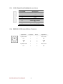
2.5.16 Audio Function
Pin
SYMBOL
Pin-Header
C0~C4
B1~B4
A1~A4
Line in
Line out
Mic in
IA31 Motherboard User Manual
19
CHAPTER
3
Graphic Driver Installation
This chapter offers information on the chipset software
Installation utility
Installation of Graphic Driver
Panel Resolution Setting
IA31 Motherboard User Manual
20
Chapter 3
Graphic Driver Installation
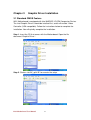
3.1 Standard CMOS Feature
IA31 Motherboard is equipped with Intel 945GSE / ICH7M Companion Device.
The Intel Graphic Drivers should be installed first, and it will enable “Video
Controller (VGA compatible). Follow the instructions below to complete the
installation. You will quickly complete the installation.
Step.1. Insert the CD that comes with the Motherboard. Open the file
document “Graphic Driver “.
Step.2. Click on “win2K_xp1429” to execute the setup.
IA31 Motherboard User Manual
21
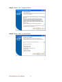
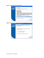
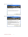
Step.3. Click on “Next “ to install Driver.
Step.4. Click on “Next “ to install Driver.
IA31 Motherboard User Manual
22
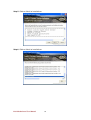
Step.5. Click on “Yes “ to agree License.
Step.6. Click on “Next “ to install Driver.
IA31 Motherboard User Manual
23
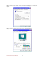
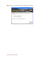
Step.7. Click on “Next “ to install Driver.
Step.8. Click on “Yes, I want to restart this computer now“ to go on.
IA31 Motherboard User Manual
24
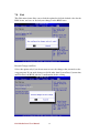
3.2 Panel Resolution Setting
Step.1. Right-click the desktop, and then click Properties.
Step.2. In the Display Properties dialog box, click the Settings tab.
Step.3. Click on “Monitor”.
IA31 Motherboard User Manual
25
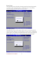
Step.4. Click on “Hide modes that this monitor cannot display” to remove this
option.
Step.5. Click on “Setting”, then could choose 32bit color qualify.
IA31 Motherboard User Manual
26
CHAPTER
4
Chipset Driver Installation
This chapter offers information on the chipset software
Installation utility
Installation of Chipset Driver
Further information
IA31 Motherboard User Manual
27
Chapter 4
Chipset Driver Installation
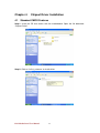
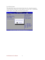
4.1 Standard CMOS Features
Setp.1. Insert the CD that comes with the motherboard. Open the file document
“Chipset Driver”.
Setp.2. Click on “infinst_auto.exe“ to install driver.
IA31 Motherboard User Manual
28
Setp.3. Click on “Next“ to install driver.
Setp.4. Click on “Yes “ to agree License
IA31 Motherboard User Manual
29
Setp.5. Click on “Next“ to install driver.
Setp.6. Click on “Next“ to install driver.
IA31 Motherboard User Manual
30
Step.7. Click on “Yes, I want to restart this computer now“ to go on.
IA31 Motherboard User Manual
31
CHAPTER
5
Ethernet Driver Installation
This chapter offers information on the Ethernet software
installation utility.
Sections include:
Introduction
Installation of Ethernet Driver
IA31 Motherboard User Manual
32
Chapter 5
Ethernet Driver Installation
5.1 Introduction
IA31 Motherboard is equipped with the Realtek RTL8111B Gigabit Ethernet controller
combines a triple-speed IEEE 802.3 compliant Media Access Controller (MAC) with a
triple-speed Ethernet transceiver, PCI Express bus controller, and embedded memory.
With state-of-the-art DSP technology and mixed-mode signal technology, it offers
high-speed transmission over CAT 5 UTP cable or CAT 3 UTP (10Mbps only) cable.
Functions such as Crossover Detection & Auto-Correction, polarity correction,
adaptive equalization, cross-talk cancellation, echo cancellation, timing recovery, and
error correction are implemented to provide robust transmission and reception
capability at high speeds.
The device supports the PCI Express 1.0a bus interface for host communications with
power management and is compliant with the IEEE 802.3u specification for
10/100Mbps Ethernet and the IEEE 802.3ab specification for 1000Mbps Ethernet. It
also supports an auxiliary power auto-detect function, and will auto-configure related
bits of the PCI power management registers in PCI configuration space.
IA31 Motherboard User Manual
33
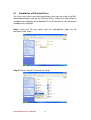
5.1
Installation of Ethernet Driver
The Users must make sure which operating system you are using in the IA31
Motherboard before installing the Ethernet drivers. Follow the steps below to
complete the installation of the Realtek RTL8111B LAN drivers. You will quickly
complete the installation.
Step.1. Insert the CD that comes with the motherboard. Open the file
document “LAN Driver”.
Step.2 Click on “Setup” to execute the setup.
IA31 Motherboard User Manual
34
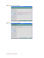
Step.3. Click on “Next“ to install driver.
Step.3. Click on “Install“ to install driver.
IA31 Motherboard User Manual
35
Setp.3. Click on “Finish“ and go on.
IA31 Motherboard User Manual
36
CHAPTER
6
Audio Driver Installation
This chapter offers information on the Audio software
installation utility.
Sections include:
Introduction
Installation of Audio Driver
IA31 Motherboard User Manual
37
Chapter 6
Audio Driver Installation
6.1 Introduction
The IA31 Motherboard is equipped with the ALC655 is a 16-bit, full-duplex AC'97 Rev.
2.3 compatible six-channel audio CODEC designed for PC multimedia systems,
including host/soft audio and AMR/CNR-based designs..
The ALC655 CODEC provides three pairs of stereo outputs with 5-bit volume control,
a mono output, and multiple stereo and mono inputs, along with flexible mixing, gain,
and mute functions to provide a complete integrated audio solution for PCs.
6.2
Installation of Audio Driver
The users must make sure which operating system you are using in the IA31
Motherboard before installing the Audio drivers. Follow the steps below to complete
the installation of the Realtek ALC655 Audio drivers. You will quickly complete the
installation.
Step.1. Insert the CD that comes with the motherboard. Open the file document
“alc655_driver” and click on “Setup.exe” to execute the setup.
IA31 Motherboard User Manual
38
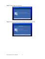
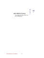
Step.2. Click on “Next“ to install driver.
Step.3. Click on “Yes, I want to restart my computer now” to finish installation.
IA31 Motherboard User Manual
39
This chapter describes how to set
BIOS configuration
IA31 Motherboard User Manual
40
CHAPTER
AMI BIOS Setup
7
Chapter 7
7.1
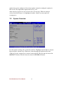
AMI BIOS SETUP
Starting Setup
Your computer comes with a hardware configuration program called BIOS Setup that
allows you to view and set system parameters.
The BIOS (Basic Input / Output System) is a layer of software, called ‘firmware’, that
translates instructions from software (such as the operating system) into instructions
that the computer hardware can understand. The BIOS settings also identify installed
devices and establish special features.
ENTERING BIOS SETUP
You can access the BIOS program just after you turn on your computer. Just press the
DEL key when the following prompt appears:
Press <DEL> to enter Setup.
When you press <DEL> to enter BIOS Setup, the system interrupts the Power-On
Self-Test (POST).
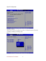
When you first enter the BIOS Setup Utility, you will enter the Main setup screen.
You can always return to the Main setup screen by selecting the Main tab. There are
two Main Setup options. They are described in this section. The Main BIOS Setup
screen is shown below.
The Main BIOS setup screen has two main frames. The left frame dis- plays all the
IA31 Motherboard User Manual
41
options that can be configured. Grayed-out options cannot be configured; options in
blue can be. The right frame displays the key leg- end.
Above the key legend is an area reserved for a text message. When an option is
selected in the left frame, it is highlighted in white. Often a text message will
accompany it.
7.2
System Overview
Use this option to change the system time and date. Highlight System Time or System
Date using the <Arrow> keys. Enter new values through the keyboard. Press the
<Tab> key or the <Arrow> keys to move between fields. The date must be entered in
MM/DD/YY format. The time must be entered in HH:MM:SS format
IA31 Motherboard User Manual
42
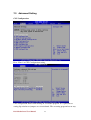
7.3
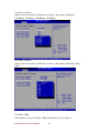
Advanced Setting
CPU Configuration
Press “Enter” to CPU Configuration setting.
CPU configuration differs from writing an executable program. It is equivalent to
setting dip switches or jumpers on a circuit board. The executing program has no way
IA31 Motherboard User Manual
43
to change this configuration.
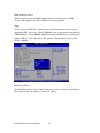
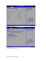
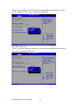
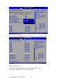
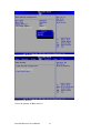
IDE/SATA Configuration
IDE Channel IO Master
While entering setup, the BIOS automatically detects the presence of IDE
devices. This displays the status of IDE device auto-detection.
IA31 Motherboard User Manual
44
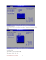
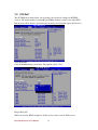
IDE Channel IO Slave
While entering setup, the BIOS automatically detects the presence of IDE
devices. This displays the status of IDE device auto-detection.
Type
Select the type of IDE drive. Setting to Auto allows automatic selection of the
appropriate IDE device type. Select CDROM if you are specifically configuring a
CD-ROM drive. Select ARMD (ATAPI Removable Media Device) if your device
either is ZIP, LS-120, or MO drive. The options: [Not Installed], [Auto], [CD/
DVD], [ARMD].
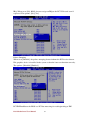
LBA/Large Mode
Enabling LBA causes Logical Block Addressing to be used in place of Cylinders,
Heads and Sectors. The options: [Disabled], [Auto].
IA31 Motherboard User Manual
45
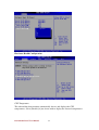
Block (Multi-Sector Transfer)
Controls enabling of multi-sector transfer, if supported. The options:
[Disabled],[Auto].
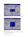
PIO Mode
Indicates the type of PIO (Programmed Input/Output).
IA31 Motherboard User Manual
46
DMA Mode
Indicate the type of Ultra DMA. The options: [Auto], [SWDMan], [MWDMAn],
[UDMAn].
S.M.A.R.T
This allows you to activate the S.M.A.R.T. (Self-Monitoring Analysis & Reporting
IA31 Motherboard User Manual
47
Technology) capability for the hard disks. S.M.A.R.T is a utility that monitors your
disk status to predict hard disk failure. This gives you an opportunity to move data
from a hard disk that is going to fail to a safe place before the hard disk becomes
offline.
32Bit Data Transfer
Enable 32-bit communication between CPU and IDE card. The options: [Enabled],
[Disabled].
IA31 Motherboard User Manual
48
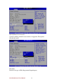
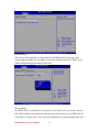
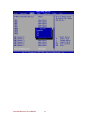
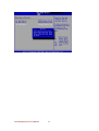
Super IO Configuration
Serial Port 1 Address
Allows you to select the Serial Port1 base address. Configuration options: [Disabled]
[3F8/IRQ4] [2F8/IRQ3] [3E8/IRQ4] [2E8/
IRQ3].
IA31 Motherboard User Manual
49
Serial Port 2 Address
Allows you to select the Serial Port2 base address. The options: [Disabled],
[3F8/IRQ4], [2F8/IRQ3], [3E8/IRQ4], [2E8/IRQ3].
Serial Port 3 Address
Allows you to select the Serial Port3 base address. The options: [Disabled], [3E8],
[2E8].
Serial Port 3 IRQ
Allow BIOS to select Serial Port 3 IRQ. The options: [4], [9], [10], [11]
IA31 Motherboard User Manual
50
Serial Port 4 Address
Allows you to select the Serial Port4 base address. The options: [Disabled], [3E8],
[2E8].
Serial Port 4 IRQ
Allow BIOS to select Serial Port 4 IRQ.
The options: [3], [9], [10], [11].
IA31 Motherboard User Manual
51
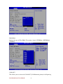
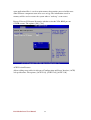
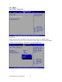
Hardware Health Configuration
CPU Temperature
The onboard hardware monitor automatically detects and displays the CPU
temperatures. Select [Disable] if you do not wish to display the detected temperatures.
IA31 Motherboard User Manual
52
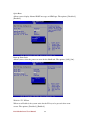
ACPI Configuration
General ACPI Configuration
IA31 Motherboard User Manual
53
Suspend Mode
This item specifies the power saving modes for ACPI function. If your operating
system supports ACPI, you can choose to enter the Standby mode in S1 (POS) or S3
(STR) fashion through the setting of this field.
These options:
[S1 (POS)] The S1 sleep mode is a low power state. In this state, no system context is
lost (CPU or chipset) and hardware maintains all system contexts. [S3 (STR)] The S3
sleep mode is a lower power state where the information of system configuration and
IA31 Motherboard User Manual
54
open applications/files is saved to main memory that remains powered while most
other hardware components turn off to save energy. The information stored in
memory will be used to restore the system when a "wake up” event occurs.
Repost Video on S3 Resume Determine whether to invoke VGA BIOS post on
S3/STR resume. The options: [No], [Yes].
ACPI Version Features
Allows adding more tables for Advanced Configuration and Power Interface (ACPI)
2.0 specifications. The options: [ACPI V1.0], [ACPI V2.0], [ACPI V3.0].
IA31 Motherboard User Manual
55
ACPI APIC Support
Allows you to enable or disable the Advanced Configuration and Power Interface
(ACPI) support in the Application-Specific Integrated Circuit (ASIC). When set to
Enabled, the ACPI APCI table pointer is included in the RSDT pointer list. The
options: [Disabled], [Enabled].
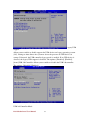
USB Configuration
IA31 Motherboard User Manual
56
Legacy USB
Support
Allows you to enable or disable support for USB devices on legacy operating system
(OS). Setting to Auto allows the system to detect the presence of USB devices at
startup. If detected, the USB controller legacy mode is enabled. If no USB device is
detected, the legacy USB support is disabled. The options: [Disabled], [Enabled],
[Auto].USB 2.0 Controller Allows you to enable or disable the USB 2.0 controller.
The options: [Disabled] [Enabled].
USB 2.0 Controller Mode
IA31 Motherboard User Manual
57
Allows you to configure the USB 2.0 controller in [HiSpeed (480 Mbps)] or [Full
Speed (12 Mbps)]. The options: [FullSpeed], [HiSpeed].
BIOS EHCI Hand-Off
Allows you enable support for operating systems without an EHCI hand-off feature.
The options: [Disabled], [Enabled].
IA31 Motherboard User Manual
58
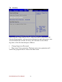
7.4 PCI/PnP
The PCI PnP menu items allow you to change the advanced settings for PCI/PnP
devices. The menu includes setting IRQ and DMA channel resources for either PCI/
PnP or legacy ISA devices, and setting the memory size block for legacy ISA devices
Clear NVRAM
Clear NVRAM during system boot. The options: [No], [Yes].
Plug & Play O/S
When set to [No], BIOS configures all the devices in the system. When set to
IA31 Motherboard User Manual
59
[Yes] and if you install a Plug and Play operating system, the operating system
configures the Plug and Play devices not required for boot.
The options: [No] [Yes].
PCI Latency Timer
Allows you to select the value in units of PCI clocks for the PCI device latency timer
register. The options: [32] [64] [96] [128] [160] [192] [224] [248].
Allocate IRQ to PCI VGA
When set to [Yes], BIOS assigns an IRQ to PCI VGA card if the card requests for an
IA31 Motherboard User Manual
60
IRQ. When set to [No], BIOS does not assign an IRQ to the PCI VGA card even if
requested. The options: [No] [Yes].
Palette Snooping
When set to [Enabled], the palette snooping feature informs the PCI devices that an
ISA graphics device is installed in the system so that the latter can function correctly.
The options: [Disabled] [Enabled].
PCI IDE BusMaster the BIOS use PCI bus mastering for reading/writing to IDE
IA31 Motherboard User Manual
61
device. The options: [Disabled], [Enabled].
OffBoard PCI/ISA IDE Card
Allows you to set the PCI slot number. The options: [Auto], [PCI Slot1], [PCI Slot2],
[PCI Slot 3], [PCI Slot4], [PCI Slot5], [PCI Slot6].
IRQ3,4,5,7,9,10,11,14,15
Allows you to specify IRQ that is available to be used by PCI/PnP or Legacy ISA
device. The options: [Available], [Reserved].
IA31 Motherboard User Manual
62
DMA Channel 0,1,3,5,6,7
DMA Channel PCI/PMP functions. The options: [Available], [Reserved].
Reserved Memory Size
Set the size of memory block to reserve for legacy ISA devices.
The options: [Disabled], [16 K], [32 K], [64 K].
IA31 Motherboard User Manual
63
IA31 Motherboard User Manual
64
7.5 Boot
Boot Setting Configuration
Quick Boot
Enable this item allows the BIOS to skip some power on self test (POST) while
booting to decrease the time needed to boot the system. When set to [Disabled], BIOS
performs all the POST items. The options: [Disabled], [Enabled].
IA31 Motherboard User Manual
65
Quiet Boot
Allows you to display Normal POST message or OEM logo. The options: [Disabled],
[Enabled].
Boot up Num-Lock
Allows you to select the power-on state for the NumLock. The options: [Off], [On].
Wait for ‘F1’ If Error
When set to Enabled, the system waits for the F1 key to be pressed when error
occurs. The options: [Disabled], [Enabled].
IA31 Motherboard User Manual
66
Boot Device Priority
Boot Device Priority
Select the priority of Boot devices.
IA31 Motherboard User Manual
67
IA31 Motherboard User Manual
68
7.6 Security
Select Security Setup from the IA31 Setup main BIOS setup menu. All
Security Setup options, such as password protection and virus protec- tion
are described in this section. To access the sub menu for the following items, select the item and press <Enter>:
ï Change Supervisor Password
ï Boot sector Virus protection: The boot sector virus protection will
warn if any program tries to write to the boot sector.
IA31 Motherboard User Manual
69
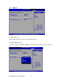
7.7 Chipset
DVMT model select
This function displays the active system memory mode.
DVMT / FIXED Memory
Specify the amount of DVMT / FIXED system memory to allocate for video memory.
IA31 Motherboard User Manual
70
Boot display device
Select boot display device at post stage. You could select Auto/VGA/LVDS
only/LVDS+VGA.
Flat panel type
Select panel resolution
IA31 Motherboard User Manual
71
7.8 Exit
This Exit menu items allow you to load the optimal or failsafe default value for the
BIOS items, and save or discard your changes to the BIOS items.
Discard Changes and Exit
Select this option only if you do not want to save the changes that you made to the
setup program. If you made changes to fields other than System Date, System time,
and Password, the BIOS asks for a confirmation before exiting.
IA31 Motherboard User Manual
72
Discard Changes
This option allows you to discard the selections you made and restore the previously
saved values. After selecting this option, a confirmation appears. Select [OK] to
discard any changes and load the previously saved values.
Load Optimal Defaults
This option allows you to load the optimal default values for each of the parameters
on the Setup menus. When you select this option or if you press <F5>, a confirmation
window appears. Select [OK] to load optimal default values. Select [Save Change and
Exit] or make other changes before saving the values to the non-volatile RAM.
IA31 Motherboard User Manual
73
Load Failsafe Defaults
This option allows you to load the failsafe default values for each of the parameters
on the Setup menus. When you select this option or if you press <F5>, a confirmation
window appears. Select [OK] to load failsafe default values.
IA31 Motherboard User Manual
74
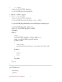
Note1: Digital I/O Sample Code
//File of the Main.cpp
//===========================================================
//This code is for test IA31 Super I/O.
//===========================================================
#include <dos.h>
#include <conio.h>
#include <stdio.h>
#include <stdlib.h>
//============================================================
#define W83627EHG_INDEX_PORT 0x2E
#define W83627EHG_DATA_PORT 0x2F
//============================================================
#define W83627EHG_REG_LD 0x07
//============================================================
#define W83627EHG_UNLOCK 0x87
#define W83627EHG_LOCK 0xAA
//============================================================
void ClrKbBuf(void);
void Unlock_W83627EHG(void);
void Lock_W83627EHG(void);
void Set_W83627EHG_Reg(unsigned char,unsigned char);
unsigned char Get_W83627EHG_Reg(unsigned char);
int main ();
//============================================================
int main ()
{
unsigned char ucDO = 0; //data for digital output
unsigned char ucDI; //data for digital input
unsigned char ucBuf;
Set_W83627EHG_Reg(0x07,0x07);//switch to logic device 7
//
//
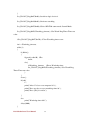
PIN 121~128 function select
Bit0 = 0 -> Game Port.
IA31 Motherboard User Manual
75
//
= 1 -> GPIO1.
ucBuf = Get_W83627EHG_Reg(0x29);
Set_W83627EHG_Reg(0x29,ucBuf|0x01);
//
//
Bit0 = 0 -> GPIO1 is inactive.
Bit1 = 1 -> Activate GPIO1.
ucBuf = Get_W83627EHG_Reg(0x30);
Set_W83627EHG_Reg(0x30,ucBuf|0x01);//Activate GPIO1
Set_W83627EHG_Reg(0xF0,0x0F);//switch GPIO Input(1)/Output(0) port
Set_W83627EHG_Reg(0xF1, 0x00); //clear
ucDI = Get_W83627EHG_Reg(0xF1) & 0x0F;
ClrKbBuf();
while(1)
{
ucDO++;
Set_W83627EHG_Reg(0xF1, ((ucDO & 0x0F) << 4));
ucBuf = Get_W83627EHG_Reg(0xF1) & 0x0F;
if (ucBuf != ucDI)
{
ucDI = ucBuf;
printf("Digital I/O Input Changed. Current Data is 0x%X\n",ucDI);
}
if (kbhit())
{
getch();
break;
}
delay(500);
}
return 0;
}
//============================================================
void ClrKbBuf(void)
{
while(kbhit())
{ getch(); }
IA31 Motherboard User Manual
76
}
//--------------------------------------------------------------------------void Unlock_W83627EHG (void)
{
outportb(W83627EHG_INDEX_PORT, W83627EHG_UNLOCK);
outportb(W83627EHG_INDEX_PORT, W83627EHG_UNLOCK);
}
//============================================================
void Lock_W83627EHG (void)
{
outportb(W83627EHG_INDEX_PORT, W83627EHG_LOCK);
}
//============================================================
void Set_W83627EHG_Reg( unsigned char REG, unsigned char DATA)
{
Unlock_W83627EHG();
outportb(W83627EHG_INDEX_PORT, REG);
outportb(W83627EHG_DATA_PORT, DATA);
Lock_W83627EHG();
}
//============================================================
unsigned char Get_W83627EHG_Reg( unsigned char REG)
{
unsigned char Result;
Unlock_W83627EHG();
outportb(W83627EHG_INDEX_PORT, REG);
Result = inportb(W83627EHG_DATA_PORT);
Lock_W83627EHG();
return Result;
}
//============================================================
IA31 Motherboard User Manual
77
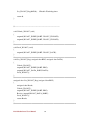
Note2: Watchdog Sample Code
//File of the Watchdog.cpp
//============================================================
//This Sample code is for Watchdog timer configuration
//============================================================
//============================================================
#include <dos.h>
#include <conio.h>
#include <stdio.h>
#include <stdlib.h>
//============================================================
#define W83627_INDEX_PORT 0x2E
#define W83627_DATA_PORT 0x2F
#define W83627_UNLOCK 0x87
#define W83627_LOCK 0xAA
//#define Watchdog_timeout 10
//============================================================
void Unlock_W83627(void);
void Lock_W83627(void);
void Set_W83627_Reg(unsigned char,unsigned char);
unsigned char Get_W83627_Reg(unsigned char);
//============================================================
int main ()
{
int Watchdog_timeout = 10;
printf("Input Watchdog Timer time-out value [0-255] : ");
scanf("%d",&Watchdog_timeout);
if(Watchdog_timeout <= 0 || Watchdog_timeout > 255)
{
printf("Time-out value out of range!!\n\n");
printf("Input Watchdog Timer time-out value [0-255] : ");
scanf("%d",&Watchdog_timeout);
IA31 Motherboard User Manual
78
}
Set_W83627_Reg(0x07,0x08);//switch to logic device 8
Set_W83627_Reg(0x30,0x01);//Activate watchdog
Set_W83627_Reg(0xF5,0x06);//Select WDTO# count mode.Second Mode.
Set_W83627_Reg(0xF6,Watchdog_timeout); //Set Watch Dog Timer Time-out
value
//Set_W83627_Reg(0xF7,0xC0); //Clear Watchdog timer event
int i = Watchdog_timeout;
while(1)
{
if (kbhit())
{
if(getch()==0x1B) //Esc
break;
else{
i=Watchdog_timeout; //Reset Watchdog timer
Set_W83627_Reg(0xF6,Watchdog_timeout); //Set Watch Dog
Timer Time-out value
}
}
clrscr();
if(i>0){
i--;
printf("After %2d sec reset computer!\n",i);
printf("Press any key to reset watchdog timer!\n");
printf("Press [Esc] to exit!\n");
}
else
printf("Watchdog timer fail!");
delay(1000);
}
IA31 Motherboard User Manual
79
Set_W83627_Reg(0xF6,0); //Disable Watchdog timer
return 0;
}
//--------------------------------------------------------------------------void Unlock_W83627 (void)
{
outportb(W83627_INDEX_PORT, W83627_UNLOCK);
outportb(W83627_INDEX_PORT, W83627_UNLOCK);
}
//============================================================
void Lock_W83627 (void)
{
outportb(W83627_INDEX_PORT, W83627_LOCK);
}
//============================================================
void Set_W83627_Reg( unsigned char REG, unsigned char DATA)
{
Unlock_W83627();
outportb(W83627_INDEX_PORT, REG);
outportb(W83627_DATA_PORT, DATA);
Lock_W83627();
}
//============================================================
unsigned char Get_W83627_Reg( unsigned char REG)
{
unsigned char Result;
Unlock_W83627();
outportb(W83627_INDEX_PORT, REG);
Result = inportb(W83627_DATA_PORT);
Lock_W83627();
return Result;
}
//============================================================
IA31 Motherboard User Manual
80
Note3:
There is some problem when install software in CF Card as following condition:
1. Master: IDE CD-ROM ( PIONEER DVD-227A )
Slave: CF Card ( Transcend 120X-standard )
CF Card is not founded.
2. Master: CF Card ( InnoDisk )
Slave: IDE CD-ROM ( Plextor PX-760A)
CD-ROM is not founded.
3. Master: CF Card ( InnoDisk )
Slave: IDE CD-ROM ( PIONEER )
CF Card is not founded.
4. Master: CF Card ( Transcend 120X-standard )
Slave: IDE CD-ROM ( Plextor PX-760A )
CD-ROM is not founded.
5. Master: IDE CD-ROM ( Plextor PX-760A )
Slave: CF Card ( Transend 120X-standard )
CF Card is not founded.
IA31 Motherboard User Manual
81