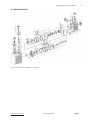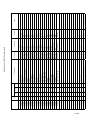
1
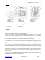
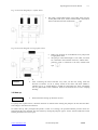
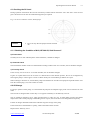
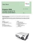
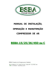
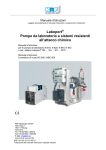
Oil Rotary Vane Two-Stage
Vacuum Pumps
Types
RTVP 16 А
RTVP 30 A
RTVP 60 А
RTVP 16 АC
RTVP 60 AC
RTVP 60 АC
OPERATING INSTRUCTIONS
Operating Instructions for RTVP
C2
1. Description ..................................................................................................................................................4
1.1 Function.................................................................................................................................................5
1.2 Supplied Equipment ..............................................................................................................................6
1.3 Transportation .......................................................................................................................................7
1.4 Technical Data.......................................................................................................................................7
2. Vacuum Safety..........................................................................................................................................10
2.1 Vacuum Pumps / Vacuum System Hazards ........................................................................................10
2.2 Hazardous Overpressure .....................................................................................................................10
2.3 Pump Oil Hazards ...............................................................................................................................10
3. Operation ..................................................................................................................................................11
3.1 Unpacking of The Pump .....................................................................................................................11
3.2 Installation...........................................................................................................................................11
3.3 Connection to the System....................................................................................................................12
3.4 Electrical Connection ..........................................................................................................................12
3.5 Start-up ................................................................................................................................................13
3.5.1 Application Areas........................................................................................................................14
3.6 Operation.............................................................................................................................................14
3.6.1. Pumping of Non-Condensable Gases.........................................................................................14
3.6.2. Pumping of Condensable Gases and Vapours............................................................................14
3.6.3 Operating Temperature ...............................................................................................................15
3.7 Switching Off / Shutdown...................................................................................................................15
3.7.1 Shut-Down ..................................................................................................................................16
3.7.2 Failure of the Control System or the Mains Power .....................................................................16
4. Maintenance..............................................................................................................................................16
4.1 Checking the Oil Level .......................................................................................................................17
4.1.1 Checking the Condition of N 62, HE 200 Oil, Shell Corena V...................................................17
4.2 Oil Change...........................................................................................................................................17
4.3 Cleaning the Dirt Trap.........................................................................................................................18
4.4 Storing the Pump .................................................................................................................................18
4.5 Maintenance plan ................................................................................................................................19
5. Troubleshooting........................................................................................................................................20
6. Repair in Authorized Service ..................................................................................................................21
7. Spare Parts................................................................................................................................................21
8. Warranty Conditions ...............................................................................................................................22
9. Clients Service ..........................................................................................................................................22
Test Report....................................................................................................................................................23
EC Declaration of Conformity ...................................................................................................................24
Declaration of Contamination of Vacuum Pumps ....................................................................................25
10. Spare Parts List ......................................................................................................................................26
www.vacuumsys.com
Vacuum El System
2/32
Operating Instructions for RTVP
C2
Indications:
Warning: Indicates procedures that must be strictly observed to prevent hazards to
persons.
Caution!
Indicates procedures that must strictly be observed to prevent damage to, or destruction of
the equipment.
---------------------------------------------------------------------------
Caution!
We recommend that you carefully read this user’s manual before you begin operation of RTVP vacuum pump. We do
not bear responsibility for accidents or damages, caused by or related to product exploitation, occurred due to nonobservance of hereby instructions. Our responsibility constitutes a quality repair service in case of troubleshooting,
and is limited within the value of the product.
Figures:
The references to figures in the text, consist of the figure No and the position No, e.g. (1/3).
Service:
If a pump is returned to a service, indicate whether the pump is free of substances damaging to health or whether it is
contaminated. If it is contaminated also indicate the nature of the hazard. Any pump, sent to a service without a
“Declaration of Contamination”, will be returned to the sender’s address, on the account of the sender.
Disposal of waste oil
Anyone in possession of used oil is responsible for its proper disposal, in accordance with the local acting regulations.
Used oils coming from vacuum pumps must not be mixed with other substances.
Used oils from vacuum pumps (on the basis of mineral oils) having been affected by normal contamination due to
oxygen from the ambient air, increases in temperature and mechanical wear, must be disposed of as used oil in
accordance with the regulations.
Used oils from vacuum pumps that have been contaminated by other substances must be labelled, stored and disposed
of as special waste with reference to the kind of contamination.
In many countries proof of where the oil has finally been left is required by Law and often shipping of such
contaminated waste requires permission by the authorities.
www.vacuumsys.com
Vacuum El System
3/32
Operating Instructions for RTVP
C2
When storing and disposing of used oil please observe the safety regulations that are valid
in your country.
1. Description
RTVP pumps are oil-sealed rotary vane two-stage vacuum pumps. The number in the type designation (RTVP 16, 30
and 60) indicates the pumping speed in m3/h, and the marks “A” or “AC” – the variant of designation – normal make
(A) and for aggressive media (AC). They are highly productive at comparatively low weight and low energy cost.
Application areas are industry, power engineering, electrical engineering, microelectronics, metallurgy,
pharmaceutics, optics, sputtering installations and others.
RTVP pumps can pump gases and vapours and evacuate vessels or vacuum systems in the fine vacuum range.
•
Pumps of standard design are not suitable for pumping greater than atmospheric
concentrations of oxygen, hazardous gases, or extremely aggressive or corrosive
media.
RTVP pumps operate through means of three-phase electric motors, having different power, depending on the
pumping speed.
Caution!
•
RTVP 16 А and RTVP 16 АC are also available with a single-phase motor.
The drive motor is directly flanged to the pump. The pump and motor shafts are directly connected by a flexible
coupling. The bearing points of the pump module are force lubricated sliding bearings. All connections are to be found
at the top of the pump. The oil-level indicator is provided with a prism for better observation of the oil level.
The pump module consists of assembly parts which are pin-fitted so as to allow easy disassembly and reassembly.
www.vacuumsys.com
Vacuum El System
4/32
Operating Instructions for RTVP
C2
Fig.1. Sectional
drawing of RTVP
1 Coupling housing
2 Coupling
3 Centrifugal switch
4 Exhaust port
5 Front-end plate
6 Rotor
7 Intermediate plate
8 Rotor Shaft
9 Oil reservoir
10 Rotor
11 Electrical motor
12 Oil-drain plug
13 Low-vacuum ring
14 High-vacuum ring
15 Oil-sight gauge
16 Anti-suckback valve
17 Dust trap filter
18 Intake port
19 Gas ballast valve – knob
20 Valve plate
21 Gas ballast valve
22 Demister
23 Exhaust valve
24 Oil nozzle
25 Vanes
1.1 Function
In accordance with Fig.1, the rotor (1/10), mounted eccentrically in the high vacuum ring (1/14), has three radially
sliding vanes (1/25) which divide the high-vacuum stage of the pump chamber into several compartments. The volume
of each compartment changes periodically with the rotation of the rotor.
As a result, gas is sucked in at the intake port (1/18). The gas passes through the dust trap filter (1/17), flows past the
open anti-suckback valve (1/16) and then enters the pump chamber. In the pump chamber, the gas is passed on and
compressed.The oil injected into the pump chamber is used for sealing and lubricating.
The compressed gas passes through intermediate plate (1/7), in the chamber of the low-vacuum stage, consisting of a
rotor (1/6) and a low-vacuum ring (1/13). The operating principle of the two stages is identical.
From the chamber of the low-vacuum stage, the compressed gas enters the pump oil reservoir, when certain pressure
through the exhaust valve (1/23) has been obtained. The oil entrained in the gas is coarsely trapped in the internal
demister (1/22); there the oil is also freed of mechanical impurities. The gas leaves the pump through the exhaust port
(1/4).
During compression, a controlled amount of air – the so called gas ballast – can be allowed to enter the pump chamber
by opening the gas ballast valve (1/21). The gas ballast stops condensation of vapours in the pump chamber up to the
limit of the water vapour tolerance. The gas ballast valve is opened and closed by turning the gas ballast knob (1/19).
The oil is separated from the gas in the pump in two steps (phases). First, small droplets are coalesced into large drops.
Then, the large drops fall into the oil reservoir as the exhaust gas is diverted by the inner walls of the oil case. Thus a
low loss of oil is obtained. This and the large usable oil reservoir ensure long intervals between oil changes even at
high intake pressures.
The vacuum in the operating media is maintained by an anti-suckback valve (1/16) which is controlled via the
centrifugal switch (1/3). During operation of the pump the control piston and the valve disc of the anti-suckback valve
are held at the lower position by their own weight (valve open).
www.vacuumsys.com
Vacuum El System
5/32
Operating Instructions for RTVP
C2
When the pump stops (because it has been switched off or because of a failure), the air pressure pushes the control
piston up. Thus a connection is provided between the pump chamber, the oil reservoir and the piston of the antisuckback valve.
Air follows in, which vents the pump chamber and forces the valve disc (1/16) against its seat. This effectively
prevents backstreaming of oil or oil vapours. The anti-suckback valve (1/16) operates independently of the operating
mode of the pump, i.e. also with gas ballast.
1.2 Supplied Equipment
Standard equipment supplied includes:
Pump with motor, including initial filling of N 62 , HE200 or Shell Corena V oil,
A set of connecting elements DN 25 KF or DN 40 KF,
depending on the concrete pump,
1 centering “O”ring,
1 centering “O”ring with dirt trap,
2 clamping rings.
For protection during shipment, the connection ports are each wrapped separately and placed in the pump package.
Switches, motor protection switch, mains cable etc. are not included.
www.vacuumsys.com
Vacuum El System
6/32
Operating Instructions for RTVP
C2
1.3 Transportation
• Pumps which are filled with operating oil must only be moved while standing in
normal /operating/ position. Otherwise oil may escape. Avoid any other orientations
during transport. Acceptable tilt degree - 15°.
Caution!
• Check the pump for the presence of any oil leaks, since there exists the danger that
someone may slip on spilt oil.
• When lifting the pump you must make use of the crane eyes provided on the pump for
this purpose; also use the recommended type of lifting device.
1.4 Technical Data
Model
Description
Free Air Pumping *
Pumping Speed **
Ultimate remaining pressure ***
- Gas-ballast – closed
- Gas-ballast – open
Ultimate working pressure ****
- Gas-ballast – closed
- Gas-ballast - open
Measure
RTVP 16A
RTVP 16AC
RTVP 30 А
RTVP 30 АC
RTVP 60 А
RTVP 60 АC
m3/h
m3/h
20
16
38
30
76
60
mbar
mbar
2,5x10⁻⁴
6,5 x10⁻³
2,5x10⁻⁴
6,5 x10⁻³
2,5x10⁻⁴
6,5 x10⁻³
mbar
mbar
≤ 4x10⁻⁴
≤ 6,5 x10⁻³
220V 1-PH
220V/380V 3-PH
0.55
1500
58
1,3
N62
12~40
NW 25/ NW 25
550(L) x 172(W)
x 290(H)
30
≤ 4x10⁻⁴
≤ 6,5 x10⁻³
≤ 4x10⁻⁴
≤ 6,5 x10⁻³
220V/380V 3-PH
220V/380V 3-PH
1.1
1500
60
3,4
N62
12~40
NW 40/ NW 40
615(L) x 242(W)
x 365(H)
73
2.2
1500
66
4,1
N62
12~40
NW 40/ NW 40
730(L) x 242(W)
x 365(H)
90
Incoming voltage (50Hz)
Electric motor power
Nominal speed, rpm
Noise level
Quantity of oil
Recommended oil
Tolerance of ambient temperature
Input / Output type
kW
min-1
DB(A)
l
°С
Dimensions
mm
Weight
kg
* Theoretical pumping speed.
** Pumping speed in working media, measured at specific laboratory conditions – gas, pressure, temperature, etc. This
speed is variable, depending on the real operation process.
*** Lowest values of pressure (with/without gas ballast), which can be obtained at specific laboratory conditions.
**** Operational pressure values (with/without gas ballast), obtainable in real conditions, in accordance with the
pump operation instructions.
All measurements of vacuum pumps parameters are done in compliance with the factory instructions.
www.vacuumsys.com
Vacuum El System
7/32
Operating Instructions for RTVP
Fig.3 – Pumping speed characteristics of RTVP vacuum pumps
www.vacuumsys.com
Vacuum El System
8/32
C2
Operating Instructions for RTVP
Fig. 4 – Dimensions of RTVP 16 A / RTVP16 AC
Fig. 5 –Dimensions of RTVP 30 A/ RTVP 30 AC
Fig. 6 – Dimensions of RTVP 60 A / RTVP 60 AC
www.vacuumsys.com
Vacuum El System
9/32
C2
Operating Instructions for RTVP
C2
2. Vacuum Safety
2.1 Vacuum Pumps / Vacuum System Hazards
Consider all possible chemical reactions within your system. Make allowance for abnormal chemical reactions,
including those, which could occur under fault conditions.
Refer to material data sheets when you assess the potential hazards, associated with your process materials.
Use dilution techniques to minimize reactions with oxidants and flammable materials.
Use manufacturers recommendations for type of lubricant in your pump when you pump oxidants and pyrophoric
materials.
When you perform safety calculations, ensure that the safe working pressure for all components in the system are
taken into account.
Ensure that you incorporate the correct type of pressure relief devices and that they are suitably rated for your
application.
If you pump hazardous materials, you must design the system to fail to a safe condition.
Leak test systems and equipment before use.
No part of the body should be exposed to vacuum. The exposure of small areas of the body surface to the suction of a
pumping system can result in tissue damage.
Exhaust hazard – Any dangerous gas substances that may be present in the system being evacuated may pass through
the system into the pump and be emitted at the exhaust. Suitable precautions must be taken.
2.2 Hazardous Overpressure
Hazardous pressures may be produced if the exhaust from an automatic pump is restricted or blocked, and care should
be taken at all time to prevent this.
Exhaust line manifold systems should be designed to cope with the maximum exhaust load that can occur.
Hazardous pressures may be produced in the system to be evacuated if the rotary pump is operated in the reverse
sense. When a rotary pump motor requires a three-phase electrical supply, the outfit should be checked for correct
rotation after main connection, before being connected to the system to be evacuated.
2.3 Pump Oil Hazards
Cleaning hazard – Suitable precautions should be taken to protect personnel, engaged in cleaning vacuum pumps from
the solvents being used and from the process debris in the pump. The exact precautions to be taken will be dependent
on the cleaning solvent involved and the applied process, but particular attention should be paid to the danger of
inhaling solvent vapours.
Oil mist hazard – Rotary pumps are oil-sealed and discharge small quantities of oil mist when operating. In poorly
ventilated areas this can lead to unacceptable concentrations of oil-vapour. Oil vapour should be kept to a minimum. It
is recommended that a suitable oil mist filter is fitted to the pump or, alternatively, the exhaust should be piped away
externally.
Oils, based on mineral products are only slightly to moderately irritating to the skin and eyes. Prolonged exposure of
the skin to mineral oils may give rise to dermatitis.
www.vacuumsys.com
Vacuum El System
10/32
Operating Instructions for RTVP
C2
Care should, however, be taken to avoid inhalation of vapours or mists, arising from undue heating or excessive mist
generation. In the case of fluorinated compounds (e.g. Fomblin), avoid contact with excessive heat (280o C), e.g.
lighted cigarettes, heater elements, etc.
Oil fluid spillage should be absorbed with sand, earth or mineral absorbent and disposed of in the proper manner. In
the event of large spillage, steps should be taken to prevent possible pollutions.
The operating temperature of the vacuum oils should be in the order of safe operating conditions in a vacuum
environment.
A hazardous condition may occur if the oil is permitted to overheat excessively (self-ignition, chemical decomposition
and emission of dangerous components, etc.).
3. Operation
3.1 Unpacking of The Pump
Once the pump has been taken out of the cardboard box, in order to operate you must:
•
•
Dismantle the metal frame, by unscrewing 6 pieces of М8 nuts, key No 13.
Dismantle the pump from the wooden panel, by unscrewing 4 pieces of М8 nuts, key No 13.
When lifting and/or moving the pump you must make use of the crane eyes provided on the pump for this purpose;
also use the recommended type of lifting device.
3.2 Installation
•
The standard pump is not suited for installation in explosion hazard areas. When
planning such an application please contact us first.
The pump must be set up on a flat, horizontal surface. The ambient temperature should not exceed +40 °C and not
drop below +12 °C. The site chosen should allow adequate air circulation to cool the pump.
Caution!
www.vacuumsys.com
•
If you wish to firmly install the pump in place, insert bolts or similar connecting
elements through the bore holes in the feet. Use rubber feets to act as vibration
absorbers. RTVP 16A and RTVP 16 AC are equipped with rubber feet.
•
When installing RTVP pump, make sure that the connections and controls are readily
accessible.
•
Max. tilt allowed, for the pump with possibly fitted standard accessories is 5° from the
vertical. The site chosen should allow adequate air circulation to cool the pump.
•
If the pump is installed on a tilt surface, the indicated oil level will be altered, and this
has to be taken into consideration.
Vacuum El System
11/32
Operating Instructions for RTVP
C2
3.3 Connection to the System
Before connecting the pump, remove the shipping seals from the exhaust (1/4) and the intake (1/18) flanges.
Caution!
•
Retain the shipping seals in case you need to store the pump in the future.
Connect the intake and
exhaust pipes, using centering ring, “O” ring and a clamp for each ring. Placing of a filter at the intake pipe is
recommendable.
Caution!
•
The intake line must be clean. Deposits in the intake line may outgas and adversely
affect the vacuum. The connecting flanges must be clean and undamaged.
•
The cross-section of the intake and exhaust lines should be at least the same size as the
connection ports of the pump. If the intake line is too narrow, it reduces the pumping
speed. If the exhaust line is too narrow, overpressures may occur in the pump; this
might damage the shaft seals and cause oil leaks.
The maximum pressure in the oil case must not exceed 1.5 bar. When pumping oil vapours, it is advisable to install
filters /condensate traps/ on the exhaust side. Install the exhaust line with a downward slope (lower than the pump) so
as to prevent condensate from flowing back into the pump. If this is not possible, insert a condensate trap.
In order to reduce the emission of oil vapours we recommend the installation of an additional exhaust filter.
•
Never operate the pump with a sealed exhaust line. There is the danger of injury.
•
Before starting any work on the pump, the personnel must be informed about
possible dangers first. All safety regulations must be observed.
3.4 Electrical Connection
•
Before beginning with any work on the wiring, ensure that mains supply for the
pump is off.
•
Electrical connections must be done by a qualified electrician in accordance with
the acting guidelines.
RTVP pumps are supplied without accessories for electrical connection. They must be connected via the appropriate
cable, and a suitable motor protection switch. Set the switch in accordance with the rating on the motor nameplate.
www.vacuumsys.com
Vacuum El System
12/32
Operating Instructions for RTVP
C2
Fig. 7 Connection diagram for a 3-phase motor.
•
The pump is connected through a 4-wire cable, three wires are
for the phase leads (R, S, and T) and the fourth is the Neutral
lead, connected to the bolt, marked with
sign
Fig. 8 Connection diagram of a single-phase motor.
•
•
Refers only to RTVP 16 А and RTVP 16 АC pumps with
a single-phase motor.
The pump is connected through a 3-wire cable, two leads
are connected to the terminals of the box, and the third –
protective lead is connected to the bolt, marked with
sign
Caution!
•
After connecting the motor and after every time you alter the wiring, check the
direction of rotation. To do so, briefly switch on the motor and check whether a
suitable cover (e. g. a blank flange) is sucked on at the intake port. If not, interchange
the two phase leads of the connection. Observe the direction arrow on the coupling
housing!
•
Each time before starting up check the oil level.
3.5 Start-up
Caution!
For pumps with 3-phase motors, check the direction of rotation before starting the pump for the first time and after
each change in the electrical connection.
On initial start-up, after prolonged idle periods or after an oil change, the specified ultimate pressure cannot be
attained until the oil is degassed. This can be done by running the pump for approx. 30 min. with the intake line closed
and the gas ballast valve (1/21) open.
www.vacuumsys.com
Vacuum El System
13/32
Operating Instructions for RTVP
C2
•
Before starting the pump ensure that the pump and the fitted accessories meet the
requirements of your application and that safe operation can be guaranteed.
•
Avoid exposure of any part of the body to the vacuum. There is the danger of injury.
Never operate the pump with an open intake port. Vacuum connections as well as oilfill and oil-drain openings must never be opened during operation.
•
The safety regulations which apply to the application in each case must be observed.
This applies to installation, operation and during maintenance (service) as well as
waste disposal and transportation.
•
The standard pumps are not suited for pumping of hazardous gases or vapours.
3.5.1 Application Areas
Caution!
•
The pump is not suitable for pumping of:
ignitable and explosive gases or vapours
oxidants
pyrophorous gases.
•
The pumps are not suitable for pumping of liquids or very dusty media. Suitable
protective devices must be installed.
3.6 Operation
RTVP pumps can pump condensable gases and vapours within the acceptable tolerance, provided that the gas ballast
valve (1/21) is open and the pump has attained its operating temperature.
3.6.1. Pumping of Non-Condensable Gases
If the process contains mainly permanent gases, the pump may be operated without gas ballast, provided that the
saturation vapour pressure at operating temperature is not exceeded during compression.
If the composition of the gases to be pumped is not known and if condensation in the pump cannot be ruled out, run
the pump with the gas ballast valve open.
3.6.2. Pumping of Condensable Gases and Vapours
With the gas ballast valve open and at operating temperature, RTVP pumps can pump pure water vapour up to the
water vapour tolerance. If the vapour pressure increases above the permissible level, the water vapour will condense in
the oil of the pump.
Caution!
•
During pumping, vapours may dissolve in the oil. This changes the oil properties and
thus there is a risk of corrosion in the pump. Therefore, don’t switch off the pump
immediately after completion of the process. Instead, allow the pump to continue
operating with the gas ballast valve open and the intake line closed until the oil is free
of condensed vapours.
We strongly recommend operating the pump in this mode for about 30 minutes after completion of the process.
www.vacuumsys.com
Vacuum El System
14/32
Operating Instructions for RTVP
C2
In cyclic operation, the RTVP pumps should not be switched off during the intervals between the individual working
phases (power consumption is minimal when the pump is operating at ultimate pressure), but should continue to run
with gas ballast valve open and intake port closed (if possible via a valve).
Once all vapours have been pumped off from a process (e.g. during drying), the gas ballast valve can be closed to
improve the attainable ultimate pressure.
3.6.3 Operating Temperature
Proper operation of the RTVP is ensured in the ambient temperature range between 12 °C to 40 °C.
•
At normal operation, the surface temperature of the oil case may exceed 80 °C,
depending on the load.
•
There is the danger of receiving burns.
3.7 Switching Off / Shutdown
Under normal circumstances, all that you need do is to electrically switch off the pump. No further measures will be
required.
Caution!
•
When pumping condensable media let the pump continue to operate with the gas
ballast valve open and the intake line closed before switching off.
•
When pumping aggressive or corrosive media, let the pump continue to operate even
during long non-working intervals (e.g. overnight) with the intake line closed and the
gas ballast valve open. This avoids corrosion during idle periods.
If the pump is to be
shutdown
for
an
extended period after
pumping aggressive or corrosive media or if the pump has to be stored, proceed as follows:
•
.
When pumping harmful substances, take adequate safety precautions:
Drain the oil.
Add clean oil until the oil-level is at the “min” mark and let the pump operate for some time. Then drain the oil and
add clean oil until the oil level is at the “max.” mark (as shown in Fig.9).
Seal the connection ports. Special conservation or anticorrosion oils aren’t necessary.
Caution!
www.vacuumsys.com
•
Please also take note of the information given in Section 4.4 (storage and storage
conditions).
Vacuum El System
15/32
Operating Instructions for RTVP
C2
3.7.1 Shut-Down
Through Monitoring Components
•
When the pump has been switched off due to overheating sensed by the motor coil
protector, the pump must only be started manually after the pump has cooled down to
the ambient temperature and after having removed the cause first.
3.7.2 Failure of the Control System or the Mains Power
•
In order to prevent the pump from running up unexpectedly after a mains power
failure, the pump must be integrated in the control system in such a way that the pump
can only be switched on again manually.
4. Maintenance
•
Disconnect the electrical connections before disassembling the pump. Make absolutely
sure that the pump cannot be accidentally started.
•
If the pump has pumped harmful substances, ascertain the nature of hazard and take
adequate safety measures. Observe all safety regulations.
If you send a pump for repair please observe the information provided in Section 6.
•
When disposing of used oil, you must observe the applicable environmental
regulations!
Due to the design concept, RTVP pumps require very little maintenance when operated under normal conditions. The
work required is described in the sections below.
Caution!
www.vacuumsys.com
•
All work must be carried out by suitably trained personnel. Maintenance or repairs
carried out incorrectly will affect the life and performance of the pump and may cause
problems when filing warranty claims.
•
If the pump has been used in ambient air which is much contaminated, make sure that
the air circulation and the gas ballast valve are not adversely affected.
•
When the RTVP has been pumping corrosive media we recommend that possibly
planned maintenance work be carried out immediately in order to prevent corrosion of
the pump while it is at standstill.
Vacuum El System
16/32
Operating Instructions for RTVP
C2
4.1 Checking the Oil Level
During operation of the RTVP the oil level must always remain between the marks “min” and “max” at the oil-level
glass. The amount of oil must be checked and topped up as required.
Fig. 9 An oil-level indicator scheme, RTVP pumps
Caution!
•
Fill in oil only after the pump has been switched
off.
4.1.1 Checking the Condition of N 62, HE 200 Oil, Shell Corena V
a) Visual check
Normally the oil is clear and transparent. If the oil darkens, it should be changed.
b) Chemical check
The neutralisation number of the oil is determined according to DIN 51558. If it exceeds 2, the oil should be changed.
c) Viscosity check
If the viscosity of N 62 oil at 25 °C exceeds 300 mPas, the oil should be changed.
If gases or liquids dissolved in the oil result in a deterioration of the ultimate pressure, the oil can be degassed by
allowing the pump to run for approx. 30 min. with the intake port closed and the gas ballast valve open.
When wanting to check the oil, switch off the pump first and drain out from the warm pump the required amount of oil
from the oil drain plug (1/12) into a beaker or similar.
4.2 Oil Change
For proper operation of the pump, it is essential that the pump has an adequate supply of the correct and clean oil at all
times.
The oil must be changed when it looks dirty or if it appears chemically or mechanically worn out.
The oil should be changed at every 2,000 operating hours or after one year. At high intake pressures and intake
temperatures and/or when pumping condensable gases or vapours, the oil will have to be changed more frequently.
Further oil changes should be made before and after long-term storage of the pump.
If the oil becomes contaminated too quickly, install a dust filter and/or oil filter.
Required tool: Allen key size 8.
www.vacuumsys.com
Vacuum El System
17/32
Operating Instructions for RTVP
Caution!
C2
•
Only change the oil after the pump has been switched off and while the pump is still
warm.
•
If there is the danger that the operating agent may present a hazard because of the
media, which have been pumped, you must ensure that all necessary safety precautions
are taken.
Remove the oil-drain plug and let the used oil drain into a suitable container. When the flow of oil slows down, screw
the oil-drain plug back in, briefly switch on the pump (max. 10 s) and then switch it off again.
Remove the oil-drain plug once more and drain out the remaining oil. Screw the oil-drain plug back in (check the
gasket and reinstall a new one if necessary).
Remove the oil-fill plug and fill in with fresh oil. Screw the oil-fill plug back in.
The quantity of oil, needed for your pump model, can be checked at the Technical Specifications (section 1.4)
4.3 Cleaning the Dirt Trap
A wire-mesh sieve is located in the intake port of the pump to act as a dirt trap for coarse particles. It should be kept
clean. For this purpose, remove the dirt trap from the intake port and rinse it in a suitable vessel with solvent. If the
dirt trap is defective, replace it with a new one.
Caution!
•
The cleaning intervals depend on the application. If the pump is exposed to large
amounts of abrasive materials, a dust filter should be fitted into the intake line.
4.4 Storing the Pump
•
The pump should be stored in a dry place preferably within the operating temperature
(12 °C - 40 °C). Before the pump is shelved it must be properly disconnected from the
vacuum system, purged with dry nitrogen and the oil should be changed too. The inlets
and outlets of the pump must be sealed with the shipping seals, which are provided
upon delivery.
•
The gas ballast switch must be set to the “closed” position.
Caution!
When a pump is put into operation after it has been shelved for over one year, standard maintenance should be run on
the pump and the oil should also be exchanged (see “Operation” and “Maintenance”).
www.vacuumsys.com
Vacuum El System
18/32
Operating Instructions for RTVP
C2
4.5 Maintenance plan
•
Maintenance before switching on the system
Check the oil level, change the oil if required. Oil: N 62 or special and alternative oils. Refill: only
after the pump has been switched off.
Check the quality of the oil, change the oil if required. Visually: normally light and transparent, oil
change is required when discolorations increase.
•
Daily maintenance
Operate the pump for at least 30 minutes with gas ballast. Condensed water is thus removed from
the oil.
Check the oil level, change the oil if required. Oil: N 62 or special and alternative oils. Refill: only
after the pump has been switched off.
Check the quality of the oil, change the oil if required. Visually: normally light and transparent, oil
change is required when discolorations increase.
•
6 monthly maintenance
Check the oil level, change the oil if required:
Chemically: according to DIN-51558;
Mechanically: when dynamic viscosity at 25 °C exceeds 300 mPas; then an oil change will be
required.
Clean the dirt trap in the intake port, change it as required. Use suitable cleaning agent and
compressed air. Observe the safety regulations when using cleaning agents.
Service Maintenance of the Pump
This kind of maintenance is done only in the service, specified in the Warranty Card!
•
Annual maintenance ( at the client’s premises )
Check of the teeth edges on the coupling element for any damages;
Oil change;
Cleaning of the oil level glass;
Checking of the fan of the pump and the motor as well as the cooling fins on the motor for deposits
Measurement of pump parameters;
•
Maintenance at every two years ( in service )
Complete disassembly and cleaning of the pump components;
Checking of the individual components;
Oil change;
Change of all gaskets and seals;
Visual check and measurement of the vanes;
Measurement of pump parameters and functional check;
www.vacuumsys.com
Vacuum El System
19/32
Operating Instructions for RTVP
C2
5. Troubleshooting
Fault
Pump does not start
Possible cause
Wiring is malfunctioning.
Motor protection switch incorrectly set
(3-phase motors only).
Operating voltage does not match motor.
Remedy
Check and repair wiring.
Set motor protection switch properly.
Section*
3.4
Replace the fault element.
service
Motor is malfunctioning.
Oil temperature is below 12 °C.
Oil is too viscous.
Replace the motor.
Heat the pump and pump oil or use different oil.
Change the oil.
service
3.6.3/4.2
4.2
Measuring technique or gauge is
unsuitable.
External leak **
Exhaust valve is malfunctioning.
Oil is unsuitable.
Intake line is dirty.
Pump is too small.
Use correct measuring technique and gauge.
service
Repair the pump.
Repair the valve.
Change the oil (degas it, if necessary).
Clean vacuum lines.
Check the process data; replace the pump, if
necessary.
service
service
4.2
-
Pumping speed is too
low
Dirt trap in the intake port is clogged.
Exhaust filter is clogged.
Connecting lines are too narrow or too
long.
Clean the dirt trap;
Exchange the filter element.
Use adequately wide and short connecting lines.
4.3
3.3
After switching off
pump under
vacuum, pressure in
system rises too
fast.
System has a leak.
Anti-suckback valve is malfunctioning.
Check the system.
Repair the valve.
service
Pump gets hotter
than usually
observed.
Cooling air supply is obstructed.
Ambient temperature is too high.
Process gas is too hot.
Oil cycle is obstructed.
Exhaust filter or exhaust line is
obstructed.
Exhaust valve is malfunctioning.
Pump module is worn out.
Set pump up correctly.
3.2
Set the vacuum system correctly.
Clean or repair the oil lines and channels.
Replace the exhaust filter, clean the exhaust line.
4.2
service
-
Repair the valve.
Replace the pump module.
service
service
Oil in the intake line
or in vacuum
vessel.
Oil comes from the vacuum system.
Anti-suckback valve is damaged.
Sealing surfaces of anti-suckback valve
are damaged or dirty.
Check the vacuum system.
Clean or repair the valve.
Clean or repair the intake port and the anti-suckback
valve.
service
service
Oil is turbid.
Condensation.
Degas the oil or change the oil and clean the pump.
2.5.2/4.2
Pump is excessively
noisy.
Oil level is much too low (oil is no longer
visible).
Intake pressure is too high.
Coupling element is worn.
Vanes or bearings are damaged.
Add oil.
4.2
Lower the intake pressure.
Install new coupling element.
Repair pump.
3.6
service
Oil-leak from the vacuum pump.
Pump works too long at high intake
pressure.
Repair the leak.
Install an oil-trap at the exhaust line and/or optimize
the vacuum system.
-
Pump does not reach
ultimate pressure
Oil-level falls too fast
* Repair information: refer to the Section in the Operation Instruction stated here.
** Bubble test: the warm pump with degassed oil is running without gas ballast and the intake blanked off. The
exhaust line is led in to a vessel with water. If an evenly spaced line of bubbles appears, then the pump has an external
leak.
www.vacuumsys.com
Vacuum El System
20/32
Operating Instructions for RTVP
C2
6. Repair in Authorized Service
When you have purchased a pump, you have also received a Warranty Card, completed and sealed by the Seller. It
indicates the corresponding service, which will be serving your pump in case of warranty defects and maintenance, in
accordance with the plan in section 4.5.
If a pump is returned to a service for maintenance, indicate whether the pump is free of substances damaging to health
or whether it is contaminated. If it is contaminated also indicate the nature of the hazard. For this you must use a form
which has been prepared by us. Please make a copy and fill in the form - “Declaration of Contamination of Vacuum
Pumps”. This “Declaration of Contamination” is required for the protection of our personnel. Any pump, sent to a
service without a “Declaration of Contamination” will be returned to the sender’s address, on his account.
•
The pump must be packed in such a way, that it will not be damaged during shipping
and so that any contaminants are not released from the package.
7. Spare Parts
In order to ensure normal operation of the vacuum pump and to avoid any hazards, relating to its exploitation, the
manufacturer recommends repair of the pump and replacement of spare parts in an authorized service only.
The authorized services have all necessary spare parts on stock and are in position to provide fast and competent
assistance for the service of the product.
•
www.vacuumsys.com
In case a repair or a service maintenance is needed, please observe the instructions for
transportation, maintenance and repair, pointed in sections 1.3, 4.5 and 6.
Vacuum El System
21/32
Operating Instructions for RTVP
C2
8. Warranty Conditions
We – “Vacuum El System” Ltd., herewith declare that the hereby product is made of quality materials and guarantee
normal pump operation, provided that all instructions in the hereby User’s Guide are observed.
Warranty period is 24 months from date of purchase.
Change of mechanical elements, including but not limited with oil, shaft seals, filters and others, made with concern to
normal service maintenance, are not subject of this warranty.
This warranty will be void in case of pumps, damaged by improper transportation or non-observance of instructions
for operations and storage (e.g. operated at high ambient temperature, polluted media, corrosive or explosive liquids
and gases) as well as in cases, when an attempt from third persons or companies has been made to repair the
malfunction.
Limitation of liabilities: Liabilities are limited to repair and renovation or replacement of the pump, at the
choice of “Vacuum El System”.
9. Clients Service
Each time, when you address us, in order to get service, maintenance or advise, please provide information about the
model, the pump serial number and the date of purchase. Please, refer to the seller’s invoice or the information plate,
attached to the pump.
www.vacuumsys.com
Vacuum El System
22/32
Operating Instructions for RTVP
Test Report
No ……………
1. Product:
ID No:
Name:
2. Technical parameters:
Parameter
Ultimate operational pressure without gasballast
Ultimate operational pressure with gasballast
Measure
Requirement
mbar
≤ 4х10-4
mbar
≤ 6,5 . 10-3
Pump operational temperature
0
C
≤ 80
At ambient temperature
0
C
12 ~ 40
Test technician: ….. ………………………..
Metrologist: ………………………..
/St. Stoilov/
www.vacuumsys.com
Measured
/T. Hristov/
Vacuum El System
23/32
C2
24/32
Operating Instructions for RTVP
C2
Declaration of Contamination of Vacuum Pumps
The repair and/or service of vacuum pumps will only be carried out if a correctly completed declaration has been
submitted. The manufacturer or the authorized service has the right to refuse to accept any pump without a declaration.
This declaration can only be completed and signed by authorized personnel.
Vacuum pumps, which have been contaminated by biologically active or explosive substances, will not be accepted
without written evidence of decontamination.
1. Description of the vacuum pump:
- model / type:
- serial No:
- invoice No:
2. Reason for return of the vacuum pump:
_______________________________________________________________________________________________
_______________________________________________________________________________________________
_______________________________________________________________________________________________
3. Condition of the vacuum pump:
- has the pump been used?
yes
no
- what type of pump oil/liquid has been used? __________________________________
- is the pump free from potentially harmful substances?
yes (go to Section 5)
no
(go to Section 4)
4. Process related contamination of vacuum pump:
- toxic
- corrosive
- explosive
- biological hazard
- radioactive
- other harmful substances
yes
yes
yes
yes
yes
yes
no
no
no
no
no
no
Please, list all substances, gases and by-products, which may have come into contact with the pump.
Trade name,
Product name,
Manufacturer
1.
2.
3.
4.
Chemical name
(or symbol)
Dangerous
class
material Measures if spillage
First aid in case of
human contact
5. Declaration
Undersigned _______________________________________________ hereby declare that the information supplied
on this form is complete and accurate. The dispatch of the contaminated vacuum pump will be in accordance with the
appropriate regulations covering packaging, transportation and labeling of dangerous substances.
Name of organization or company: __________________________________________________________________
Address: __________________________________________________________; Post code: ___________________
Tel.: ______________________________________________________; Fax: _______________________________
Name: ________________________________________________________________________________________
Job title: _______________________________________________________________________________________
Date: __________________
www.vacuumsys.com
Legally binding signature: _______________________
(company stamp)
Vacuum El System
25/32
Operating Instructions for RTVP
10. Spare Parts List
Fig.2. Detailed scheme of RTVP vacuum pump
www.vacuumsys.com
Vacuum El System
26/32
C2
27/32
1
1
1
2
1
1
1
1
2
2
1
1
1
1
4
5
5
6
6
7
7
7a
7a
8
9
10
11
11
12
12
12
13
13
14
15
801134
801241
801250
800766
800767
802013
802017
802367
802369
801477
801133
801448
800103
800102
800113
800112
800111
801135
801136
800133
800565
2
4
15 b
16
16
17
801299
801303
800602
800558
1
1
15 a
801137
1
1
1
2
2
1
1
1
1
2
1
2
4
801127
2
3
802369
2
1
2
2
1
1
3
2
800685
1
30 А
802367
1
16 А
Pump Model
800684
1
800778
Pos.
800779
Cat. No. VES
2
2
1
1
1
1
1
1
2
2
1
1
1
1
2
2
1
1
60 А
INTAKE TUBE
GAS BALLAST VALVE STEM
BASE
RUBBER FOOT
SEAL"
SEAL"
OIL LEVEL GLASS
HANDLE
SEAL"
SEAL"
OIL CASING
OIL CASING
OIL CASING
COUPLING HOUSING
COUPLING HOUSING
EYE BOLT
PLUG GASKET"
PLUG SCREW"
O-RING"
O-RING"
CENTERING RING
CENTERING RING
EXHAUST PORT
EXHAUST PORT
O-RING"
O-RING"
FLAT GASKET"
FLAT GASKET"
O-RING"
O-RING"
FILTER (Dirt trap-mesch)
FILTER
INTAKE TUBE
Description
351 67 206
461 75 107
279 80 308
520 40 125 .3
520 40 125 .2
520 40 125
283 02 107
238 11 142
238 11 126
333 72 128
333 72 123
330 72 124
333 58 116
331 55 139
201 13 101
239 55 165
201 27 105
239 70 516
239 70 506
231 94 207
231 94 206
433 60 117
433 60 115
239 70 304
239 70 117
238 20 158
238 20 156
239 70 516
239 70 506
411 70 206
411 70 121
433 60 119
431 65 116
Cat.№ Leybold
Dimension
60 x 40
D 20 x 16
D 43 x 50 x 2
D 68 x 60 x 2
106 x 120 x 32
242 x 270 x 1
172 x 190 x 1
200,5x172,5x192,5
246.5x242x279.5
321.5x242x279.5
265x172,5x216,5
164x242x272.5
Al-aly, St
Steel
NBR
Viton
Viton
C Al - aly
Thermolit
Thermolit
C Al - aly
C Al - aly
C Al - aly
C Al - aly
Cast iron
Steel
Viton
D 22 х 15,1 х 2
M8
Steel
Viton
Viton
D 16 x 1,5
D 42 x 5
D 28 x 5
Al
Al
KF 40
Al - aly
KF 25
Al - aly
Viton
Viton
AFM
AFM
Viton
Viton
Steel
Steel
Al - aly
Al - aly
Material
KF 25 x 42
KF 40 x 63
D 45 x 3
D 29 x 3
D 75 x 84
D 55 x 63
D 42 x 5
D 28 x 5
KF 25
KF 40
KF 25 x 70
KF 40 x 107
Spare Parts List of RTVP pump models
*Not suply separately
Notes
28/32
COVER
RETAINING RING
1
1
1
1
1
1
1
1
1
1
21
22
23
23
24
24
25
25
26
27
28
29
30
31
31
800711
800701
801225
801255
801402
801400
801139
801138
801425
801401
801130
800702
801433
801142
800662
34
35
35
801125
34
800740
800742
33b
800202
801126
33b
800203
1
1
1
33a
800200
33a
33
33b
33
802516
802515
800204
1
33
802517
800201
1
32
32
801302
801300
1
1
1
1
1
20
801237
1
1
1
1
1
1
1
1
1
1
1
1
1
19
1
1
1
1
1
1
1
1
1
1
1
1
1
1
1
1
1
CENTRIFUGAL SWITCH
CENTRIFUGAL SWITCH
KEY (COUPLING)
KEY (COUPLING)
COUPLING ELEMENT (motor side)
COUPLING ELEMENT (motor side)
COUPLING ELEMENT (motor side)
COUPLING ELEMENT (pump side)
COUPLING ELEMENT (pump side)
COUPLING COMPLETE(pos 32& pos.33)
COUPLING COMPLETE
COUPLING COMPLETE
COUPLING ELEMENT"
COUPLING ELEMENT"
OIL SEPARATOR
OIL FILTER
VALVE PLATE (gas ballast)"
SPRING (GAS BALLAST)^
RETAINING RING
FLAT CASKET"
FLAT CASKET (gas ballast)"
SPRING (FILTER)
SPRING (FILTER)
O-RING"
O-RING"
STIFFENING DISK
RETAINING WASHER
O-RING"
VALVE gas ballast(Assy)
CAP
801132
GAS BALLAST VALVE STEM
1
1
1
1
Description
1
60 А
18
30 А
17
16 А
801109
Pos.
Pump Model
800555
Cat. No. VES
500 36 147
500 36 128
221 16 179
221 16 151
570 42 129
570 42 113
570 42 112
570 42 129.4
570 42 113-3
411 12 108
390 26 117
231 03 106
341 01 109
401 64 117
221 62 140
231 04 104
239 25 226
239 25 225
221 62 143
221 62 142
239 70 148
239 70 147
222 04 107
221 49 207
239 70 436
350 20 158
349 75 105
351 67 207
Cat.№ Leybold
Dimension
D 60 x 26
D 70 x 27
6 x 6 x 22
5 x 5 x 18
D 58 x 61
D 82 x 83
D 82 x 83
D 50 x 15
D 75 x 20
D 60 x 90
D 42 x 55
17 x 1
D 46 x 1,5
D 14,8 x 0,2
D 15 x 11,5
15 x 1
D 30 x 16 x 1
D 30 x 18 x 1
D 20 x 35
D 25,2 x 38
D5x2
D 16 x 2,5
D 40 x 0,5
D 19,5 x 33 x 0,9
D 27 x 2,5
D 31,7 x 6
D 50 x 40
Spare Parts List of RTVP pump models
Brs,Steel
Brs,Steel
Steel
Steel
Cast iron
Cast iron
Cast iron
Cast iron
Cast iron
Cast iron/Buna
Cast iron/Buna
Cast iron/Buna
Buna
Buna
Stainless steel
Stainless steel
Steel
Al
Steel
Steel
Steel
Viton
Viton
Steel
Steel
Viton
Viton
Brass
Steel
Viton
Termoplast
NBR
Al-aly, St
Material
не са в/у фиг.1
не са в/у фиг.1
Notes
29/32
1
2
1
1
1
1
37
38
39
40
40
800589
801399
801140
800165
800168
4
42
42
43
43
44
44
44
44а
44а
801288
800191
800190
801258
801222
802510
802511
802512
800508
800509
1
1
46
46
46
47
47
48
48
49
801117
801120
801121
801116
801115
800149
800150
801146
1
1
46
801119
3
45
45
1
1
1
1
3
3
1
1
1
1
3
44b
800640
801147
1
801148
1
1
44а
44b
1
4
1
2
1
1
800627
1
1
4
1
1
1
1
3
60 А
800510
1
1
1
1
41
41
801291
2
1
37
800588
1
3
1
36
30 А
36
16 А
801426
Pos.
Pump Model
801421
Cat. No. VES
VANE^
INTERMEDIATE PLATE
INTERMEDIATE PLATE(Center bearing)
VALVE STOP
VALVE STOP
VALVE PLATE (corrosive)"
VALVE PLATE (corrosive)"
VALVE PLATE (normal)"
VALVE PLATE (normal)^
VANE
VANE^
ROTOR (2nd stage) W/Oshaft
ROTOR (2nd stage)W/Oshaft
SHAFT (2nd stage)
SHAFT(2nd stage)
SHAFT (2nd stage)
ROTOR WITH SHAFT
ROTOR WITH SHAFT
ROTOR(2ND STAGE) WITH SHAFT
O-RING"
O-RING"
SECOND STAGE PUMP CYLINDER
SECOND STAGE PUMP CYLINDER
RADIAL SHAFT SEAL"
RADIAL SHAFT SEAL"
FRONT END PLATE
FRONT END PLATE
SEAL (LEVER)"
SPRING (LEVER)
LEVER
LEVER
RETAINING RING^
RETAINING RING
Description
401 64 125
411 55 115
261 51 135
261 51 131
373 58 107
32,5 x 150 x 4,5
D 30 x 22
D 15 x 15
63 x 45 x 9
80 x 74,5 x 12
63 x 45 x 0,1
373 58 106
75 x 82 x 0,2
63 x 45 x 0,1
75 x 82 x 0,2
22 x 45 x 4,5
32,5 x 75 x 4,5
D 68 x 45
D 101 x 75
D 22 x 365
D 22 x 290
D 15 x 228
101x365
D101x290
D68x228
D 122 x 3
D 86 x 2
D 79 x 45
D 118,5 x 75
D 15 x 32 x 7
D 22 x 40 x 7
D 22 x 27
D 15 x 23
D 9 x 11
D 8,5 x 23
88 x 40 x 1
109 x 40 x 1
D 22 x 1,2
D 15 x 1
Dimension
401 64 124
401 64 116
401 64 114
411 55 155
411 55 116
321 66 121
321 66 119
401 57 296.2
401 57 294.2
401 27 292.2
481 21 241
481 21 240
481 21 239
239 70 411
239 70 156
231 58 124
231 58 122
239 53 142
239 53 110
301 51 140
301 51 137
239 73 131
221 62 141
281 53 102
281 53 101
231 03 111
231 03 104
Cat.№ Leybold
Spare Parts List of RTVP pump models
Incutex
Cast iron, Brz
Cast iron, Brz
Black plastic
Al - aly
Gold plated
Gold plated
Stainless steel
Stainless steel
X-lon
Incutex
Cast iron
Cast iron
Steel
Steel
Steel
CI,St
CI,St
CI,St
Viton
Viton
Cast iron
Cast iron
Viton
Viton
Cast iron, Brz
Cast iron, Brz
Viton
Steel
StSt
St St
Steel
Steel
Material
Only for models AC
Only for models AC
Notes
30/32
1
51
51
52
52
53
53
54
54
55
55
56
800180
800181
801106
801107
800744
800743
801111
801113
800590
800591
800136
2
2
2
1
1
1
1
59
60
60
60
61
61
62
63
63
64
801372
800747
800746
800748
800748
800749
801104
801112
801129
800504
2
4
4
59
801371
3
4
58
800729
3
58
58
800727
1
800728
1
1
56
57
800506
2
2
1
1
3
30 А
800139
1
1
1
1
1
51
800179
1
50
50
50
800627
3
800635
49
16 А
Pump Model
800628
49
801145
Pos.
801147
Cat. No. VES
1
1
2
2
2
3
3
1
1
2
2
2
2
1
1
60 А
PISTON (ballast)
VALVE DISK"
VALVE DISK"
AIR NOZZLE
CYLINDRICAL PIN
CYLINDRICAL PIN
CYLINDRICAL PIN
CYLINDRICAL PIN
CYLINDRICAL PIN
HEXAGON NUT
HEXAGON NUT
THREADED STUD
THREADED STUD
THREADED STUD
DISK OIL SLINGER
REAR END PLATE
REAR END PLATE
RETAINING BRACKET
RETAINING BRACKET
VALVE PLATE"
VALVE PLATE "
KEY ROTOR
KEY ROTOR
OIL NOZZLE
OIL NOZZLE
PUMP CYLINDER, HV(1st) STAGE
PUMP CYLINDER, HV STAGE
PUMP CYLINDER, HV STAGE
ROTOR, HV STAGE
ROTOR, HV STAGE(1 stage)
ROTOR, HV STAGE
VANE^
VANE^
Description
D 8 x 218
321 06 104
400 50 139
400 50 137
392 25 204
241 03 593
241 03 590
241 03 590
241 03 586
241 03 585
211 01 314
211 01 312
201 52 110
D 12 x 30
D 32
D 45
0.36
D 8 x 60
D 8 x 40
D 8 x 40
D 8 x 24
D 8 x 20
D8
D6
D 6 x 178
D 8 x 293
201 52 106
201 52 108
D 85 x 2,1
D 22 x 26
D 15 x 17
52 x 4 x 4
40 x 10 x 8
25 x 25 x 5
16 x 16 x 5
6 x 6 x 50
5 x 5 x 28
1.5
0.8
D 79 x 90
D 118,5 x 75
D 118,5 x 150
D 68 x 90
D 101 x 150
D 101 x 75
22 x 90 x 4,5
32,5 x 75 x 4,5
Dimension
451 74 335
351 55 132
351 55 130
491 60 111
491 60 107
400 50 138
400 50 135
221 16 188
221 16 156
392 25 124
392 25 113
231 65 122
231 65 118
231 65 107
321 66 122
321 66 120
321 66 119
411 55 154
411 55 116
Cat.№ Leybold
Spare Parts List of RTVP pump models
Brass
Steel/Viton
Steel/Viton
Brass
Steel
Steel
Steel
Steel
Steel
Steel
Steel
Steel
Steel
Steel
Steel
Cast iron, Brz
Cast iron, Brz
Steel
Steel
Steel/Viton
Steel/Viton
Steel
Steel
Brass
Brass
Cast iron
Cast iron
Cast iron
Cast iron
Cast iron
Cast iron
X-lon
Incutex
Material
не са в/у фиг.1
не са в/у фиг.1
Notes
31/32
1
1
68
68
68
801170
801171
801173
Major Repair Kit (for pump model AC)
All parts marked with " are included in Seal Kits and Major Repair kits
All parts marked with ^ are included Major Repair kits
1
"
^
802605
D6
D5x2
D 8 x 92,5
Major Repair Kit
Major Repair Kit (for pump model AC)
D 12 x 22
Dimension
D 8 x 143
1
1
802603
231 05 108
239 70 148
431 31 177
431 31 174
321 06 131
Cat.№ Leybold
802604
Major Repair Kit
Major Repair Kit (for pump model AC)
1
802602
Major Repair Kit
1
1 Seal Kit
Seal Kit
Seal Kit
GAS BALLAST VALVE -ASSEMBLY
GAS BALLAST VALVE -ASSEMBLY
Motor -50Hz,220/380V 3PH, 2.2kW,1400rpm
Motor -50Hz,220/380V 3PH, 1.1kW,1380rpm
Motor -50Hz,220/380V 3PH, 0.55kW,1380rpm
Motor -50Hz,220V 1PH, 0.55Kw,1380rpm
RETAINER DISK^
O-RING"
AIR INLET TUBE
1
1
1
1
1
2
PISTON
AIR INLET TUBE
Description
802601
1
1
1
1
1
1
60 А
802600
802616
802615
802614
802501
802 500
1
1
67
801420
68
2
66
801255
801174
1
65
800674
2
1
1
65
30 А
64
16 А
800673
Pos.
Pump Model
800505
Cat. No. VES
Spare Parts List of RTVP pump models
Steel
Viton
Steel
Steel
Brass
Material
Includes pos.17 -31
Includes pos.17 -31
Notes
Operating Instructions for RTVP
MANUFACTURER:
VACUUM EL SYSTEM LTD.
1, Yambolen Str.
8600 Yambol
Bulgaria
E-mail: [email protected]
www.vacuumsys.com
Vacuum El System reserves the right to modify the design and the specified data.
www.vacuumsys.com
Vacuum El System
32/32
C2