1
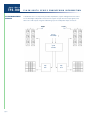
datasheet
F L A S H L I G H T ® S E R I E S E N G I N E E R I N G I N F O R M AT I O N
The Flashlight TFS-780 System is a fully integrated long
loudspeaker and covers the frequency range
throw sound reinforcement system in an extremely compact
between 150Hz and 1k3Hz. The smaller TurboMid™
and manageable form. It is supplied as a system package
device is fitted with an intensively developed 6.5"
comprising loudspeaker enclosures; amplifier racks; a
cone loudspeaker covering the frequency range
system controller and all the requisite cables and
between 1k3Hz and 8kHz. This combination of
connectors. This combination of components is configured
TurboMid™ devices represents an unprecedented
as the ideal "building block" for the creation of spherical
step in the use of cone-type transducers up to 8kHz,
arrays, providing a formidable system for large arena use.
resulting in increased reliability and power handling
The Flashlight system is easily capable of delivering full
and a startling improvement in acoustic clarity and
range (30 - 20kHz), very low distortion, coherent sound in the
detail over any compression driver working in the
biggest indoor or outdoor venues.
same band. This leaves the remaining frequencies
The TFS-780H uses very narrow dispersion pattern
components. These are further developments of
(8kHz - 20kHz) to be easily handled by a custom 1”
(25mm) compression driver.
Turbosound's Proportional Directivity™ in a very
All the units in the TFS-780H are correctly time-
high-Q enclosure and enables seamless coverage
aligned within the system controller, which is pre-
over a massive area with anything from 1/2 to 1/4
set during manufacture. In addition, user-
the number of conventional enclosures, depending
controllable time alignment adjustment
on the distance from the array. In reality this also
compensates for the physical displacement of
means that many applications that would normally
the bass devices with respect to the mid-high
require distributed delays will no longer need them.
enclosures. The combination of the amplifier
The loudspeakers are divided into two uniformly
sized enclosures: the TFS-780L and the TFS-780H.
The TFS-780L covers the low frequencies in the
power, coupled with very high efficiency drivers
equates to considerable sound pressure levels
being achieved with exceptional clarity.
range 30 - 150Hz and contains a 21" loudspeaker
The control system comprises a digital crossover
with a 6" voice coil, loaded with a TurboBass™
with factory-loaded crossover programs, high
device. The TFS-780H consists of two specially
performance limiters, electronically balanced inputs
developed long-throw TurboMid™ devices, and a
and outputs and an auto-switching
high-Q 25mm (1") waveguide horn. The larger
power supply.
TurboMid™ device is driven by a very powerful 12"
TFS-780
The power amplifiers are designed specifically for
use with the Flashlight system. They are capable of
delivering the high power level demands that the
loudspeaker system is capable of converting into
acoustic energy. The amplifiers are supplied in a
19" rack unit in groups of four, complete with all the
necessary wiring and multi-pin connectors.
To take full advantage of such a highly tuned
FEATURES
Total system optimisation
system, with such accurately defined dispersion
Negligible harmonic
characteristics, Turbosound's engineers have
distortion
developed a safe, flexible and ingeniously simple
flying and lifting system. This allows the creation of
Proportional directivity
clusters and arrays with full control of the angular
inclinations between adjacent enclosures to suit a
variety of requirements.
APPLICATIONS
Stadium and arena
installation
Touring and festivals
datasheet
TFS-780H
DIMENSIONS (HXWXD)
NET WEIGHT
COMPONENTS
F L A S H L I G H T ® S E R I E S E N G I N E E R I N G I N F O R M AT I O N
825mm x 574mm x 773mm (32.5” x 22.6" x 30.4")
87kg (191 lbs)
1 x 12” (305mm) LMF driver, 1 x 6.5” (165mm) HMF driver, 1 x 1” (25mm) HF compression driver
FREQUENCY RESPONSE1
150Hz – 20kHz ±4dB
NOMINAL DISPERSION2
25°H x 25°V @ -6dB points
POWER HANDLING
LMF: 250 watts r.m.s., 500 watts program, 625 watts peak
HMF: 100 watts r.m.s., 200 watts program, 250 watts peak
HF: 25 watts r.m.s., 50 watts program, 65 watts peak
SENSITIVITY3
MAXIMUM SPL
CROSSOVER
LMF: 107dB, 1 watt @ 1metre; HMF: 111dB, 1 watt @ 1metre; HF: 110dB, 1 watt @ 1 metre
136dB continuous4, 142dB peak5
Active
LMF/HMF: 1k3Hz, 24dB/octave, Linkwitz-Riley
HMF/HF: 8kHz, 24dB/octave, Linkwitz-Riley
NOMINAL IMPEDANCE
CONSTRUCTION
LMF: 8 ohms, HMF: 16 ohms, HF: 16 ohms
18mm (3/4”) birch plywood throughout; rebated, screwed and glued. Finished in TurboBlue™
semi-matt textured paint. Eight recessed carrying handles. Detachable wheel board
GRILLE
CONNECTORS
OPTIONS
SPARES AND
ACCESSORIES
Cloth/expanded metal
(2) 6-pin EP6 wired; pin1 LMF-; pin2 LMF+; pin3 HMF-; pin4 HMF+; pin5 HF-; pin6 HF+
Flying System – refer to the “Flying and Lifting” section
LS-1203
1 x 12” (305mm) LMF loudspeaker
LS-6501
1 x 6.5” (165mm) HMF loudspeaker
CD-103
1 x 1” (25mm) HF compression driver
RC-1203
Recone kit for LS-1203
RD-6501
Recone kit for LS-6501
RD-103
Replacement diaphragm for CD-103
MG-780
Replacement cloth/expanded metal grille
PX-780
Internal passive HF filter
W-3
Heavy duty wheel
Notes
1
Measured on axis
2
Average over stated bandwidth
3
Average over stated bandwidth
4
Unweighted diode-clipped pink noise. Measured in a half space environment.
5
Verified by subjective listening tests of familiar program material, before the onset of perceived signal degradation.
page 2
datasheet
F L A S H L I G H T ® S E R I E S E N G I N E E R I N G I N F O R M AT I O N
825mm x 574mm x 773mm (32.5” x 22.6" x 30.4")
90 kg (198 lbs)
1 x 21” (533mm) LF driver on a TurboBass™ device
50Hz – 150Hz ±4dB
600 watts r.m.s., 1200 watts program, 1500 watts peak
101dB 1 watt @ 1metre
131dB continuous3, 136dB peak4
8 ohms
18mm (3/4” birch plywood throughout; rebated, screwed and glued. Finished in TurboBlue™
TFS-780L
DIMENSIONS (HXWXD)
NET WEIGHT
COMPONENTS
FREQUENCY RESPONSE1
POWER HANDLING
SENSITIVITY2
MAXIMUM SPL
NOMINAL IMPEDANCE
CONSTRUCTION
semi-matt textured pain. Four recessed carrying handles
Cloth/expanded metal
(2) XLR-3 wired: pin 1-; pin 2+
Flying System – refer to the “Flying and Lifting” section
LS-2101
1 x 21” (533mm) LF loudspeaker
RC-2101
Recone kit for LS-2101
MG-780
Replacement cloth/expanded metal grille
W-3
GRILLE
CONNECTORS
OPTIONS
SPARES AND
ACCESSORIES
Heavy duty wheel
Notes
Measured on axis
2
Average over stated bandwidth
3
Unweighted diode-clipped pink noise. Measured in a half space environment.
4
Verified by subjective listening tests of familiar program material, before the onset of perceived signal degradation
1
page 3
datasheet
TFS-780
F L A S H L I G H T ® S E R I E S E N G I N E E R I N G I N F O R M AT I O N
Sound Pressure Level in dB
120
FREQUENCY
RESPONSE
SYSTEM
110
100
90
80
70
20 Hz 50
100 200
500
1 kHz 2
5
10
20
Frequency
TFS-780L LOW FREQUENCY
TFS-780H LOW-MID FREQUENCY
130
Ref.
Fundamental
10% Power
110
120
Sound Pressure Level in dB
120
Sensitivity
1W/1M
90
80
1.0%
2nd Harmonic
10% Power
3rd Harmonic
10% Power
Sensitivity
1W/1M
100
90
1.0%
80
70
2nd Harmonic
10% Power
3rd Harmonic
10% Power
0.2%
60
100 200
500 1 kHz 2
5
0.1%
20 Hz 50
10 20
100 200
Frequency
5
10 20
TFS-780H LOW-MID FREQUENCY
300
200
300
200
100
100
Ohms
Ohms
500 1 kHz 2
Frequency
TFS-780L LOW FREQUENCY
16
10
8
16
10
8
4
4
2
2
1
1
20 Hz 50
100 200
500
1 kHz2
Frequency
page 4
0.2%
60
20 Hz 50
NOTES ON
MEASUREMENT
CONDITIONS
Distortion %
100
70
IMPEDANCE
Ref.
Fundamental
10% Power
110
Distortion %
Sound Pressure Level in dB
130
5
10
20
20 Hz 50
100 200
500
1 kHz2
5
10 20
Frequency
Impedance A common method, constant current circuit was use to measure the impedance. Frequency Response The
frequency response shown was obtained by feeding a swept sine wave through the system in a half-space environment.
The position of the microphone was vertically on-axis, horizontally in-line with the MF/HF section at a distance of 3
metres, then scaled to represent 1 metre. 2nd & 3rd Harmonic Distortion Distortion measurements were obtained using an
Audio Precision harmonic distortion analysis system and comply with AES recommendations for enclosure measurement
(AES Paper reference: ANSI S4-26-1984). Data Conversion All graphs were digitally generated using the APEX custom
software system, designed to translate data derived from Brüel & Kjæl and Audio Precision “System One” test
equipment into AutoCAD™. This program enables graphical information to be plotted to an accuracy of more than four
decimal places.
datasheet
F L A S H L I G H T ® S E R I E S E N G I N E E R I N G I N F O R M AT I O N
TFS-780H HIGH-MID FREQUENCY
TFS-780H HIGH FREQUENCY
110
90
70
1.0%
2nd Harmonic
10% Power
3rd Harmonic
10% Power
120
Fundamental
10% Power
Ref.
110
Distortion %
Sensitivity
1W/1M
Sound Pressure Level in dB
Fundamental
10% Power
Distortion %
Sound Pressure Level in dB
Ref.
120
80
FREQUENCY
RESPONSE
130
130
100
TFS-780
Sensitivity
1W/1M
100
90
80
70
2nd Harmonic
10% Power
3rd Harmonic
10% Power
1.0%
0.2%
60
0.1%
60
20 Hz 50
100 200
500 1 kHz2
5
10 20
0.2%
20 Hz 50
100 200
Frequency
5
10 20
Frequency
TFS-780H HIGH FREQUENCY
TFS-780H HIGH-MID FREQUENCY
300
200
300
200
100
100
Ohms
Ohms
500 1 kHz2
16
10
8
16
10
8
4
4
2
2
1
IMPEDANCE
1
20 Hz 50
100 200
500
1 kHz2
Frequency
5
10 20
20 Hz 50
100 200
500
1 kHz2
5
10 20
Frequency
Impedance A common method, constant current circuit was use to measure the impedance. Frequency Response The
frequency response shown was obtained by feeding a swept sine wave through the system in a half-space environment.
The position of the microphone was vertically on-axis, horizontally in-line with the MF/HF section at a distance of 3
metres, then scaled to represent 1 metre. 2nd & 3rd Harmonic Distortion Distortion measurements were obtained using an
Audio Precision harmonic distortion analysis system and comply with AES recommendations for enclosure measurement
(AES Paper reference: ANSI S4-26-1984). Data Conversion All graphs were digitally generated using the APEX custom
software system, designed to translate data derived from Brüel & Kjæl and Audio Precision “System One” test
equipment into AutoCAD™. This program enables graphical information to be plotted to an accuracy of more than four
decimal places.
NOTES ON
MEASUREMENT
CONDITIONS
page 5
datasheet
TFS-780
DIRECTIVITY ISOBARS
F L A S H L I G H T ® S E R I E S E N G I N E E R I N G I N F O R M AT I O N
500 Hz
1 kHz
MF
MF
-3dB
-12dB
-9dB
-6dB
-3dB
20°
40°
60°
80°
100° 120°
2 kHz
4 kHz
MF
HF
-15dB
-12dB
-9dB
-6dB
-3dB
20°
40°
60°
80°
100° 120°
8 kHz
16 kHz
MF
HF
-3dB
-15dB
page 6
40°
60°
80°
100° 120°
-15dB
-12dB
-9dB
-6dB
-3dB
20°
40°
60°
80°
100° 120°
40°
60°
80°
100° 120°
-3dB
20°
TURBOSOUND
ISOBAR DATA
20°
40°
60°
80°
100° 120°
20°
-15dB
The spherical co-ordinate isobar data was computed from points taken from longitude and latitude polar measurements
around the enclosure at 10° increments. Larger scale drawings are available; please consult your dealer. All isobar
information was gathered by Turbosound Research & Development, England.
datasheet
F L A S H L I G H T ® S E R I E S E N G I N E E R I N G I N F O R M AT I O N
HORIZONTAL
0°
0°
30
10
90°
0°
0°
30
40
12
21
0°
180°
20
0°
15
0°
15
10
0°
24
12
0
180°
40
21
0°
40
30
30
20
20
10
24
10
0
0°
10
270° 0
10
90°
°
60
40
0°
°
30
60
20
30
°
0°
33
30
°
0°
33
0°
10
DIRECTIVITY ISOBARS
VERTICAL
30
10
270° 0
BEAMWIDTH
360
300
Degrees between -6dB points
TFS-780
200
100
90
80
70
60
50
40
30
20
Horizontal
Vertical
10
20 Hz
50
100
200
500
1 kHz 2
5
10
20
Frequency
24
200
100
18
50
15
20
12
10
9
5
6
3
2
0
1
20 Hz
50
100
200
500
1 kHz 2
5
10
DIRECTIVITY
Directivity Factor Q
Directivity Index dB
21
20
Frequency
All the polar measurements were taken using Audio Precision and MLSSA test equipment, with a microphone placed at a
distance of 4 metres from the rotational axis of the loudspeaker enclosure under test. This method reduces the effect that
the interaction between the MF and HF has on the measurements. For clarity, the polar information is displayed with
progressively thinner lines from 250Hz to 16kHz in third octave steps. The beam-width plots were computed from the
third octave polars. The enclosures were measured in a half space environment. All polar information was gathered by
Turbosound Research & Development, England. All graphs are digitally generated using the APEX custom software
system, designed to translate data derived from Brüel & Kjær and Audio Precision “System One” test equipment into
AutoCAD™. This program enables graphical information to be plotted to an accuracy of more than four decimal places.
NOTES ON
MEASUREMENT
CONDITIONS
page 7
datasheet
TFS-780
SYSTEM MANAGEMENT
OVERVIEW
F L A S H L I G H T ® S E R I E S E N G I N E E R I N G I N F O R M AT I O N
A dedicated series of components provides amplification, system management and control
for the Flashlight loudspeaker enclosures. The system accepts line level input signals, and
takes care of all aspects of signal conditioning up to the loudspeaker input connectors.
Flying
Flying
bar
Bar
Flying
Flying
Barbar
Stereo in
Stereo
In
Left and
Right
Left
& Right
System
System
Controller
Controller
Amp
Amp
Rack
Rack
page 8
Amp
Amp
Rack
Rack
datasheet
F L A S H L I G H T ® S E R I E S E N G I N E E R I N G I N F O R M AT I O N
The LMS-D6 digital loudspeaker management system consists of two inputs and six outputs
configured for control of all the signal, phase and time parameters required to operate the
TFS-780
SYSTEM
MANAGEMENT
loudspeaker enclosures effectively. It comprises 24dB per octave Linkwitz-Riley crossovers,
high performance limiters, variable delays, electronically balanced inputs and outputs, and a
switching power supply that automatically adjusts to mains input voltages between 90 volts
and 260 volts. It is supplied as a 1U high unit and has adjustable controls for time
compensation when the TFS-780L bass enclosures are displaced relative to the TFS-780H
mid-high enclosures. Two LMS-D6 controllers are required for a Flashlight system. No other
signal conditioning or processing is necessary and the unit is supplied factory aligned, tested
and ready for use.
LMS-D6
< BACK
NEXT>
MENU
ENTER
FREQ
'Q'
GAIN
A
B
1
CLIP
BYPASS
O
MAINS IN ~
90V - 240V AC
50 - 60Hz 30W
POWER
RS232
DATA INPUT
CAUTION! FOR CONTINUED
PROTECTION AGAINST FIRE
REPLACE ONLY WITH THE
SAME TYPE T1A, 250V FUSE
4
3
LIM
LIM
5
LIM
6
LIM
-3
-3
-3
-3
-3
-24
MUTE -24
MUTE -24
MUTE -24
MUTE -24
MUTE -24
MUTE
LMS-D6 FLASHLIGHT
SYSTEM CONTROLLER
OUT
DIGITAL LOUDSPEAKER MANAGEMENT SYSTEM
I
2
LIM
-6
GAIN
OUTPUT 6
WARNING / AVIS
OUTPUT 5
GAIN
GAIN
OUTPUT 4
OUTPUT 3
GAIN
GAIN
OUTPUT 2
GAIN
OUTPUT 1
GAIN
GAIN
INPUT B
INPUT A
PUSH
PUSH
DO NOT EXPOSE TO RAIN OR MOISTURE
THIS EQUIPMENT MUST BE EARTHED
SHOCK HAZARD - DO NOT REMOVE COVERS
RISQUE DE CHOC ELECTRIQUE - NE PAS OUVRIR
PIN1=SHIELD
PIN2=HOT
PIN3=COLD
CUSTOM MADE FOR TURBOSOUND
IN THE UK BY XTA ELECTRONICS
LMS-D6 TECHNICAL
SPECIFICATIONS
44mm x 482mm x 300mm (1.75” x 19" x 11.8")
3.5 kg (7.5 lbs)
2 inputs, 6 outputs
±0.5dB, 20Hz - 20kHz
>110dB, 20Hz - 20kHz Unwtd.
<0.02% @ 1kHz, + 18dBu
10k ohms, electronically balanced
AC Mains 50/60Hz, 60V or250V ±15%
<20 watts
(2) XLR 3 - 31 (3 pin female XLR type)
adjustable +15dB to -40dB in 0.1dB steps
Electronically balanced
(6) XLR 3 - 32 (3 pin male XLR type)
+20Bm into 600 ohms
DIMENSIONS (HXWXD)
NET WEIGHT
CROSSOVER TYPE
FREQUENCY RESPONSE
DYNAMIC RANGE
DISTORTION (THD)
INPUTS
POWER SUPPLY
POWER CONSUMPTION
INPUT CONNECTORS
INPUT GAIN
OUTPUTS
OUTPUT CONNECTORS
MAXIMUM OUTPUT LEVEL
page 9
datasheet
TFS-780
SYSTEM
AMPLIFICATION RACK
F L A S H L I G H T ® S E R I E S E N G I N E E R I N G I N F O R M AT I O N
The Turbosound Flashlight System has been designed in conjunction with state-of-the-art
power amplifiers. Four power amplifiers are supplied, housed in a 12U, steel spaceframe
equipment rack. The standard configuration is: 2 x TMC-750 amplifiers (for high and highmid), and 2 x TMC-1250 amplifiers (for low-mid and low). The power amplifiers occupy 10U
of the total space available, 2U being devoted to incoming AC power distribution and multiway signal and speaker connections. Removal of a bridging plug at the rear of the connector
panel allows the rack to be used in two channel (stereo) mode. Remote control cards are
fitted to each amplifier, enabling digital remote control and monitoring of Flashlight systems.
The mains connection panel comprises a ‘Wago’ mains distribution block, mounted on a fully
enclosed steel panel, with a captive cable fitted with a ‘C-form’ heavy duty mains connector.
The system can be configured for either a single or three phase star supply. This will suit the
majority of contemporary connection methods for both 110/120 volt and 220/240 volt mains.
Audio connections are made with the superb 12 pin Lemo video-type multi-connectors for
line level inputs, and 19 pin 20A screw lock multi-connectors to carry the high level output
signals. The rack is supplied with two 4 metre fan-outs; one multi-way to XLR for TFS-780L
enclosures, and one multi-way to EP6 for TFS-780H enclosures. A 2.5 metre Lemo to Lemo
signal cable is supplied with each rack for interconnection; custom stage return systems can
be supplied to specific customer requirements. Socapex 19 way 2.5mm multi-core speaker
extensions are optionally available in 12.5 metre or 25 metre lengths for flown speaker
enclosures. Two 3-pin XLR connectors are provided for remote control input and link. The
complete equipment rack is identical to previous BSS-equipped racks and is housed in a
heavy duty road case with wheels and snap-back handles. CE certified racks are available for
those countries where certification is required.
BOTH CHANNELS.
SIGNAL
CH1
-3
-6
-9
Temp.
BOTH CHANNELS.
CH1
INPUT
OR
LINK
-6
-9
Fault
HIGH OUTPUTS
0 dB
Limit
-3
-12
CH1
CH2
Ch.B
0 dB
2 ohm
CH2
LOW OUTPUTS
CH2
Ch.A
Fault
-15
Bridged
-12
-15
-20
-20
-25
-25
Mute
Mute
Link
REMOTE CONTROL DATA
POWER
INPUT
AND
LINK
Ch.A
0 dB
0 dB
Limit
-3
-3
-6
2 ohm
AMP-780.2
Ch.B
-6
-9
-12
-9
Fault
Temp.
Fault
-15
Bridged
-12
-15
-20
-20
-25
-25
Mute
Link
Mute
POWER
Ch.A
Ch.B
0 dB
0 dB
Limit
-3
Low Z
-3
-6
-9
-6
Fault
Temp.
Fault
-15
Mute
Bridged
-9
-15
-25
-25
Link
Mute
POWER
Ch.A
Ch.B
0 dB
0 dB
Limit
-3
Low Z
-3
-6
-9
-6
Fault
Temp.
-15
Mute
-25
Fault
Bridged
-9
-15
Link
-25
Mute
POWER
REAR
FRONT
AMP-780.2
SPECIFICATIONS
DIMENSIONS (HXWXD) (IN ROAD CASE)
NET WEIGHT
DIMENSIONS (HXWXD) (EXCL. ROAD CASE)
NET WEIGHT
page 10
800mm x 570mm x 820mm (31.5” x 22.4" x 33.3")
196 kg (431 lbs)
590mm x 512mm x 693mm (23.2” x 20.2” x 27.3”)
152kg (334 lbs)
datasheet
F L A S H L I G H T ® S E R I E S E N G I N E E R I N G I N F O R M AT I O N
TFS-780
POWER AMPLIFIERS
Ch.A
Ch.B
0 dB
0 dB
Limit
-3
Low Z
-3
-6
-9
-6
Fault
Temp.
Fault
-15
Mute
Bridged
-9
-15
Link
-25
-25
Mute
POWER
TMC-750
Ch.A
Ch.B
0 dB
0 dB
Limit
-3
Low Z
-3
-6
-9
-6
Fault
Temp.
-15
Mute
-25
Fault
Bridged
-9
-15
Link
-25
Mute
POWER
TMC-1250
TMC-750
88mm x 480mm x 410mm (3.5” x 19" x 16")
22 kg (48.4 lbs)
Into 8 ohms: 425w/channel; Into 4 ohms: 750w/channel; Into 2 ohms: 750w/channel
>90dB, 20Hz - 20kHz
Unmeasureable
<-105dB relative to full output
>0.1%, 20 - 20kHz at any level below clip. Typically 0.01%
230V AC @ 10A max. or 120V AC @ 20A max
DIMENSIONS (HXWXD)
NET WEIGHT
POWER OUTPUT
CMRR
CROSSTALK
NOISE
DISTORTION
POWER
REQUIREMENTS
TMC-1250
130mm x 480mm x 460mm (5.1” x 19" x 18.1")
32 kg (70.4 lbs)
Into 4 ohms: 1250w/channel; Into 2 ohms: 1800w/channel
>80dB, 20Hz - 2kHz
Unmeasureable
<-105dB relative to full output
>0.3%, 20 - 20kHz at any level below clip
230V AC @ 20A max. or 120V AC @ 35A max
DIMENSIONS (HXWXD)
NET WEIGHT
POWER OUTPUT
CMRR
CROSSTALK
NOISE
DISTORTION
POWER
REQUIREMENTS
page 11
datasheet
TFS-780
FLYING AND LIFTING
HARDWARE
F L A S H L I G H T ® S E R I E S E N G I N E E R I N G I N F O R M AT I O N
The Flashlight System may be supplied with a purpose designed lifting system which allows
a wide range of adjustment to the horizontal and vertical angles between adjacent
enclosures. The overall inclination between of each vertical column is also adjustable. Thus
arrays can easily be achieved to suit a multitude of coverage requirements and allow the
user to take advantage of the Proportional Directivity™ characteristics of the TFS-780H
enclosures. Sound radiating from adjacent enclosures will successfully blend over a wide
range of included angles, resulting in the ability to tailor not only the overall coverage, but
also desired SPL at a distance. Most of the above adjustments may be made while the
system is in the air and, because of the ingenious design of the flying hardware, the system
will always remain in perfect physical balance. Horizontal adjustment is in 5° increments
from 0° (transit position) to 30°, by swivel, locked by a spring loaded pin. Vertical adjustment
between enclosures is from approximately 2° to 20° using the shortening hooks fitted to
every enclosure’s suspension chains. Vertical inclination of each column is continuously
adjustable over an arc of approximately 45°; this will ultimately depend on the number of
enclosures in a column, and is achieved with a ratchet strap. It is envisaged that this
function may be motorised, and remote controlled to compensate for changes in
atmospheric conditions. The TFS-780H and TFS-780L both fly with the same vertical
orientation; in many situations it may be desirable to stack the low frequency enclosures on
their sides.
page 12
datasheet
F L A S H L I G H T ® S E R I E S E N G I N E E R I N G I N F O R M AT I O N
Lifting point
FB-780A MAIN BAR
Safety point
To suspend four columns of Flashlight
enclosures with indexed horizontal adjustment
TS-780 TILTING
STRAP
One pair required
for each enclosure
to be flown.
One required for
each column of
enclosures
Lifting eye
Safety fixing
FLYING AND LIFTING
HARDWARE
FC-780 FLYING
CHAINS
Tilting strap point
Flying chain suspension point
TFS-780
(These are handed
left and right, the
left ones have RED
shortening hooks,
the right ones BLUE
shortening hooks)
FB-780/TB TWIN BAR
To suspend two columns of Flashlight enclosures with
indexed horizontal adjustment
SWL 1t
Twin bars are handed and shouldbe ordered in pairs. They
may then be converted into Main Bar Assemblies at a later
date
Tilting strap point
Flying chain suspension point
Lifting eye
Safety fixing
SWL 1t
SINGLE BAR
To suspend one
column of Flashlight
page 13
datasheet
TFS-780
F L A S H L I G H T ® S E R I E S E N G I N E E R I N G I N F O R M AT I O N
FT-780 FLY BAR TRUNK
A purpose designed fly bar trunk is optionally available, which is used to house and transport
a single FB-780A main fly bar assembly reliably and safely. Space is also provided for stowing
flying chain assemblies and tilt straps within compartments in the trunk, thereby allowing all
the hardware necessary to fly a 4-wide Flashlight cluster to be transported in a single road
case. The FT-780 is supplied complete with heavy duty wheels and recessed handles, and is
finished in TurboBlue™ semi-matt paint.
1660mm
[65.4"]
580mm
[22.8"]
810mm
[31.9"]
DIMENSIONS
RT-8WAY & RT-16 WAY
RETURNS SYSTEMS
The Flashlight System may also be supplied with a custom returns cabling system to facilitate
fast and reliable set-up and connections between system controller and amplifier racks,
available in either 8-way or 16-way returns systems.
The RT-8WAY comprises to channels of 4-way signal connections, and consists of 100 metres
of high quality signal returns cable with lemo connectors, two 25 metre cross-stage lemo
cables and an XLR break-out panel, all housed in a rugged road case. The RT-16WAY
comprises four channels of 4-way signal connections, a 100 metre lemo return cable, four 25
metre cross-stage lemo cables and an XLR break-out panel in a road case. The XLR break-out
panel connects the LMS-700 controller (normally located at the main mix position) outputs to
the multi-way lemo cable which feeds audio signal to the on-stage amplifier racks.
page 14
datasheet
F L A S H L I G H T ® S E R I E S E N G I N E E R I N G I N F O R M AT I O N
TFS-780H
773mm
[30.4"]
574mm
[22.6"]
773mm
[30.4"]
DIMENSIONS
825mm
[32.5"]
955mm
[38.0"]
825mm
[32.5"]
574mm
[22.6"]
TFS-780
898mm
[35.4"]
page 15
datasheet
TFS-780
ARCHITECTURAL
& ENGINEER’S
SPECIFICATIONS
F L A S H L I G H T ® S E R I E S E N G I N E E R I N G I N F O R M AT I O N
The loudspeaker system shall be of the quad-amped, four-way active type comprising: two
loudspeaker enclosures loaded with patented TurboMid™ and TurboBass™ devices, high
power stereo power amplifiers mounted in a 19” equipment rack sleeve and a system
controller. All necessary system cables and connectors shall be included in the system.
Performance specifications of a typical production unit shall meet or exceed the following:Frequency response, measured with a swept sine wave input shall be flat within ±4dB from
50Hz to 20kHz. Dispersion, at -6dB points, shall average 25°H x 25°V. Total power handling
shall be 975 watts r.m.s., 1950 watts program, 2450 watts peak. Sensitivity measured with 1
watt input at 1 metre distance on axis, mean averaged between 1kHz – 18kHz shall be 111dB.
Maximum SPL (peak), measured with music program shall be 142dB. System component
dimensions shall be as follows:TFS-780H:
825mmH x 574mmW x 773mmD (32.5” x 22.6" x 30.4")
TFS-780L:
825mmH x 574mmW x 773mmD (32.5” x 22.6" x 30.4")
AMP-780.2:
800mmH x 570mmW x 820mmD (31.5” x 22.4" x 32.3")
LMS-D6:
44mmH x 482mmW x 300mmD (1.75” x 19" x 11.8")
Total enclosure volume shall not exceed 0.366 cu. metres (12.9 cu ft) for the TFS-780H and
TFS-780L. The loudspeaker system shall be the Turbosound Flashlight System. No other
system shall be acceptable unless the above combined performance specifications are
equalled or exceeded. Flying and installation hardware shall be available comprising a range
of load-certified components.
TFS-780 Version 1.2 10/99
© Turbosound 1999
TURBOSOUND Ltd Star Road Partridge Green West Sussex RH13 8RY England
tel: +44 (0) 1403 711447 fax: +44 (0) 1403 710155 • www.turbosound.com • e-mail: [email protected]