Transcript
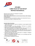
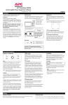
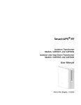
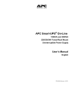
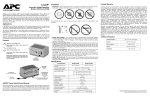
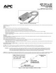
APC Category 6 Patch Panel
User’s Manual
Initial Start-up
Tools Required (not provided)
To obtain warranty coverage, please visit: warranty.apc.com
Inspection
Inspect the Patch Panel upon receipt. Notify the carrier and dealer if
there is damage. The packing is recyclable; save it for reuse or dispose of it properly.
Placement
Install the Patch Panel in a protected area that is free of excessive
dust and has adequate air flow. Do not install the Patch Panel where
temperature is outside the specified limits.
#2 Phillips Screwdriver
Cable Preperation Tool
Proper installation and termination practices
are necessary to ensure the correct operation of the patch panel. Reference the
Telecommunications Industries Association
and Electronic Industries Alliance publication
“Commercial Building, Telecommunications
Cabling standard, General Requirements”
(document number TIA/EIA-568-B.1-2001 to
ensure proper installation of wiring.
Note: Due to the amount of force required for wire
installation, it is recommended the Patch Panel be
installed on the front or rear rails of an APC
NetShelter® or any other standard rack during the
wiring process.
Warning: Changes or modifications to this unit not expressly
approved by the party responsible for compliance could void
the warranty
110 Punch Tool
Installation
1. Strip back approximately
50mm (2 in.) of cable
jacket using cable preparation tool
3. Center the cable jacket with 110 connecting block as
shown. Insert all conductor pairs into slots by pressing
firmly into position.
5. Slide termination
cap over the cable
and snap into place
prior testing.
Note: Cap removal can be
accomplished by placing a
small flat bladed screwdriver in the slots of the
cap and prying loose
BROWN
Pin #
5
4
1
2
3
6
7
8
Wire Color
white/blue
blue
orange/white
orange
green/white
green
brown/white
brown
BLUE
Pin #
5
4
1
2
3
6
7
8
Wire Color
white/blue
blue
green/white
green
orange/white
orange
brown/white
brown
Warning: Failure to keep the tool perpendicular to connecting
block during punch down may result in incorrect termination
If the channel connection is failing upon completion of the installation, perform channel and continuity test with appropriate cable tester to localize
faulty wire, panel or termination connection and
replace or repair.
Specifications
CAT6PNL-24
CAT6PNL-48
Connector 1
24 x RJ45
48 x RJ45
Connector 2
24 x 110
48 x 110
Size (H x W x D)
48.7 x 4.5 x 3.2
48.7 x 9 x 3.2
(19 x 1.7 x 1.2 in.) (19 x 3.5 x 1.2 in.)
Shipping weight
1.2 LBS
(.54 KG)
2.5 LBS
(.90 KG)
Operating
temperature
0 to +60° C
(+32 to 104°F)
0 to +60° C
(+32 to 104°F)
ULus
c
6. After cable termination, attach the
rear cable manager
7. Secure the cables
to the manager
bracket using cable
ties or hook/loop
straps (not included)
Service
Troubleshooting
Safety
and approvals
4. Terminate conductors using punch tool. Ensure tool is
perpendicular to connecting block
6 PATENTED
BLUE
A
B
c
ULus
If the device arrived damaged, notify the carrier.
If the device requires service do not return to the dealer!
Following these steps:
1. Consult the troubleshooting section to eliminate common problems.
2. If the problem still persists, call Customer Service or visit the APC Internet Website (www.apcc.com).
• Note the model number, serial number and the date of purchase. Be prepared to troubleshoot the problem with
an APC Technical Support representative. If this is not successful, APC will issue a Return Merchandise
Authorization (RMA) number and a shipping address.
• If the device is under warranty, repairs are free. If not, there is a repair charge.
3. Pack the device in its original packaging. If the original packaging is not available, ask Customer Service about
obtaining a new set.
• Pack device properly to avoid damage in transit. Never use Styrofoam beads for packaging. Damage sustained
in transit is not covered under warrant
• Include a letter with your name, RMA#, address, copy of the sales receipt, description of the trouble, your daytime phone number, and a check (if necessary)
4. Mark the RMA# on the outside of the package
5. Return the product by insured, prepaid carrier to the address given to you by Customer Service.
North & South America
APC
132 Fairgrounds Road
West Kingston, Rhode Island 02892 USA
1-800-800-4APC/1-401-789-5735
Europe
APC
Ballybritt Business Park
Galway, Ireland 10800-702000
353-91-702020
Asia Pacific
APC
Level 13 The Denison
65 Berry Street
North Sydney, NSE 2060
61 2 9955 9366
Internet: http://www.apcc.com
Local, country-specific centers: go to www.apc.com/support/contact for contact information
990-2763
Rev. A 09/05 100.14049
2. Follow the colorcoded label for
T568A/B wiring
schemes, starting
with the brown pair
on the top left IDC
positions and ending
with the blue pair on
the bottom right position.
Note: Begin at the corner of the panel where the cables enter, and work
towards the middle
A
B
BROWN