1
TC75
INTEGRATOR GUIDE
3 | Copyrights
Copyrights
The products described in this document may include copyrighted computer programs. Laws in the United States and
other countries preserve for certain exclusive rights for copyrighted computer programs. Accordingly, any
copyrighted computer programs contained in the products described in this document may not be copied or
reproduced in any manner without the express written permission.
©
2015 Symbol Technologies LLC. All Rights Reserved
No part of this document may be reproduced, transmitted, stored in a retrieval system, or translated into any language
or computer language, in any form or by any means, without the prior written permission.
Furthermore, the purchase of our products shall not be deemed to grant either directly or by implication, estoppel or
otherwise, any license under the copyrights, patents or patent applications, except for the normal non-exclusive,
royalty-free license to use that arises by operation of law in the sale of a product.
Disclaimer
Please note that certain features, facilities, and capabilities described in this document may not be applicable to or
licensed for use on a particular system, or may be dependent upon the characteristics of a particular mobile subscriber
unit or configuration of certain parameters. Please refer to your contact for further information.
Trademarks
Zebra and the Zebra head graphic are registered trademarks of ZIH Corp. The Symbol logo is a registered trademark
of Symbol Technologies LLC.
MN001975A01-A | July 2015
5 | Revision History
Revision History
Changes to the original guide are listed below:
Change
A01 Rev. A
Date
7/2015
Description
Initial release.
MN001975A01-A | July 2015
Contents | 7
Contents
Copyrights........................................................................................................................................ 3
Revision History...............................................................................................................................5
About This Guide...........................................................................................................................13
Documentation Set.............................................................................................................................................. 13
Configurations..................................................................................................................................................... 13
Software Versions............................................................................................................................................... 14
Chapter Descriptions........................................................................................................................................... 14
Notational Conventions.......................................................................................................................................14
Icon Conventions.................................................................................................................................................15
Related Documents..............................................................................................................................................15
Service Information.............................................................................................................................................15
Chapter 1: Getting Started....................................................................................17
Setup....................................................................................................................................................................17
Installing the SIM Card........................................................................................................................... 17
Installing the SAM Card..........................................................................................................................18
Installing a microSD Card.......................................................................................................................19
Installing the Hand Strap and Battery..................................................................................................... 20
Installing the Battery............................................................................................................................... 21
Charging the Battery............................................................................................................................... 22
Charging Indicators................................................................................................................................. 23
Replacing the Battery.......................................................................................................................................... 23
Replacing the microSD Card...............................................................................................................................25
Resetting the TC75..............................................................................................................................................26
Performing a Soft Reset.......................................................................................................................... 27
Performing a Hard Reset......................................................................................................................... 27
Performing an Enterprise Reset...............................................................................................................27
Performing a Factory Reset.....................................................................................................................28
Chapter 2: Accessories...........................................................................................31
Accessories..........................................................................................................................................................31
2-Slot Charge Only Cradle.................................................................................................................................. 33
Setup........................................................................................................................................................35
Charging the Device................................................................................................................................35
Charging the Spare Battery..................................................................................................................... 36
Battery Charging..................................................................................................................................... 37
2-Slot USB/Ethernet Cradle................................................................................................................................ 37
Setup........................................................................................................................................................38
Charging the Device................................................................................................................................39
Charging the Spare Battery..................................................................................................................... 39
Battery Charging..................................................................................................................................... 40
USB/Ethernet Communication................................................................................................................41
Ethernet Settings......................................................................................................................................41
Configuring Ethernet Proxy Settings.......................................................................................... 42
Configuring Ethernet Static IP Address...................................................................................... 42
5-Slot Charge Only Cradle.................................................................................................................................. 43
Setup........................................................................................................................................................44
Charging the TC75.................................................................................................................................. 44
Battery Charging..................................................................................................................................... 46
8 | Contents
Installing the Four Slot Battery Charger................................................................................................. 46
Removing the 4-Slot Battery Charger..................................................................................................... 50
5-Slot Ethernet Cradle......................................................................................................................................... 51
Setup........................................................................................................................................................52
Daisy-chaining Ethernet Cradles.................................................................................................53
Ethernet Settings..........................................................................................................................54
LED Indicators........................................................................................................................................ 55
Charging the TC75.................................................................................................................................. 56
Battery Charging..................................................................................................................................... 57
Establishing Ethernet Connection........................................................................................................... 58
Installing the 4-Slot Battery Charger.......................................................................................................58
Removing the 4-Slot Battery Charger..................................................................................................... 62
4-Slot Battery Charger.........................................................................................................................................63
Setup........................................................................................................................................................63
Charging Spare Batteries.........................................................................................................................63
Battery Charging..................................................................................................................................... 64
Magnetic Stripe Reader....................................................................................................................................... 65
Attaching the MSR..................................................................................................................................65
Removing the MSR................................................................................................................................. 66
Reading Magnetic Stripe Cards...............................................................................................................67
Magnetic Stripe Reader Notification ......................................................................................................67
MSR Provisioning....................................................................................................................... 67
Changing the Password............................................................................................................... 68
Trigger Handle.................................................................................................................................................... 68
Installing the Trigger Handle Plate......................................................................................................... 69
Inserting the Device into the Trigger Handle..........................................................................................70
Removing the Device from the Trigger Handle......................................................................................71
Hand Strap Replacement..................................................................................................................................... 72
Chapter 3: USB Communication.......................................................................... 77
Connecting to a Host Computer via USB........................................................................................................... 77
Connecting to the TC75 as a Media Device............................................................................................77
Connecting to the TC75 as a Camera......................................................................................................77
Disconnect from the Host Computer...................................................................................................................78
Chapter 4: DataWedge Configuration................................................................. 79
Basic Scanning.................................................................................................................................................... 79
Using the Imager..................................................................................................................................... 79
Profiles.................................................................................................................................................................79
Plug-ins................................................................................................................................................................80
Profiles Screen.....................................................................................................................................................81
Disabling DataWedge..............................................................................................................................83
Creating a New Profile........................................................................................................................................ 83
Profile Configuration...........................................................................................................................................84
Associating Applications.........................................................................................................................84
Data Capture Panel..................................................................................................................................86
Bar Code Input........................................................................................................................................ 88
Enabled........................................................................................................................................88
Scanner Selection........................................................................................................................ 88
Decoders......................................................................................................................................88
Decoder Params...........................................................................................................................89
Decode Lengths...........................................................................................................................93
UPC EAN Params....................................................................................................................... 93
Reader Params.............................................................................................................................94
Contents | 9
Scan Params................................................................................................................................ 95
SimulScan Input...................................................................................................................................... 96
MSR Input............................................................................................................................................... 97
Keystroke Output.................................................................................................................................... 97
Intent Output............................................................................................................................................97
Intent Overview...........................................................................................................................98
IP Output................................................................................................................................................. 99
Using IP Output with IPWedge.................................................................................................101
Using IP Output without IPWedge............................................................................................102
Generating Advanced Data Formatting Rules...................................................................................................103
Configuring ADF Plug-in......................................................................................................................103
Creating a Rule..........................................................................................................................104
Defining a Rule......................................................................................................................... 104
Defining Criteria........................................................................................................................105
Defining an Action.................................................................................................................... 107
Deleting a Rule..........................................................................................................................108
Order Rules List........................................................................................................................ 108
ADF Example........................................................................................................................................109
DataWedge Settings.......................................................................................................................................... 112
Importing a Configuration File..............................................................................................................113
Exporting a Configuration File..............................................................................................................114
Importing a Profile File......................................................................................................................... 114
Exporting a Profile................................................................................................................................ 114
Restoring DataWedge............................................................................................................................115
Configuration and Profile File Management.....................................................................................................115
Programming Notes...........................................................................................................................................116
Overriding Trigger Key in an Application............................................................................................ 116
Capture Data and Taking a Photo in the Same Application..................................................................116
Disable DataWedge on Device and Mass Deploy.................................................................................116
Soft Scan Feature...................................................................................................................................116
Chapter 5: Administrator Utilities..................................................................... 119
Required Software.............................................................................................................................................119
On-device Application Installation................................................................................................................... 119
Multi-user/AppLock Configuration.................................................................................................................. 119
Enterprise Administrator Application............................................................................................................... 120
Creating Users....................................................................................................................................... 120
Adding Packages................................................................................................................................... 121
Creating Groups.................................................................................................................................... 122
Creating Remote Authentication........................................................................................................... 122
Save Data...............................................................................................................................................123
Exporting File........................................................................................................................................123
Importing User List............................................................................................................................... 123
Importing Group List.............................................................................................................................124
Importing Package List......................................................................................................................... 124
Editing a User........................................................................................................................................124
Deleting a User......................................................................................................................................124
Editing a Group..................................................................................................................................... 124
Deleting a Group................................................................................................................................... 124
Editing a Package.................................................................................................................................. 125
Deleting a Package................................................................................................................................ 125
MultiUser Administrator................................................................................................................................... 125
Importing a Password............................................................................................................................125
Disabling the Multi-user Feature...........................................................................................................127
Enabling Remote Authentication.......................................................................................................... 127
10 | Contents
Disabling Remote Authentication......................................................................................................... 128
Enabling Data Separation......................................................................................................................128
Disabling Data Separation.....................................................................................................................128
Delete User Data................................................................................................................................... 129
Capturing a Log File..............................................................................................................................129
AppLock Administrator.................................................................................................................................... 129
Enabling Application Lock................................................................................................................... 129
Disabling Application Lock.................................................................................................................. 130
Manual File Configuration................................................................................................................................ 130
Groups File............................................................................................................................................ 131
White List File.......................................................................................................................................132
Determining Applications Installed on the Device............................................................................... 133
Package List File................................................................................................................................... 133
Secure Storage...................................................................................................................................................133
Installing a Key..................................................................................................................................... 133
Viewing Key List.................................................................................................................................. 134
Deleting a Key.......................................................................................................................................135
Volumes.................................................................................................................................................135
Creating Volume Using EFS File..............................................................................................135
Creating a Volume Manually.................................................................................................... 136
Mounting a Volume...................................................................................................................136
Listing Volumes........................................................................................................................ 137
Unmounting a Volume.............................................................................................................. 137
Deleting a Volume.....................................................................................................................137
Encrypting an SD Card..............................................................................................................137
Creating an EFS File............................................................................................................................. 137
Off-line Extraction Tool........................................................................................................................138
Usage......................................................................................................................................... 138
Creating an Image..................................................................................................................... 138
Mounting an Image................................................................................................................... 139
Unmounting an Image............................................................................................................... 139
Chapter 6: Settings...............................................................................................141
WWAN Configuration...................................................................................................................................... 141
Default SIM Slot Configuration............................................................................................................ 141
Preferred Network Selection................................................................................................................. 142
Band Preferences...................................................................................................................................142
Screen Unlock Settings..................................................................................................................................... 143
Single User Mode..................................................................................................................................143
Set Screen Unlock Using PIN................................................................................................... 144
Set Screen Unlock Using Password.......................................................................................... 144
Set Screen Unlock Using Pattern.............................................................................................. 145
Multiple User Mode.............................................................................................................................. 146
Passwords.......................................................................................................................................................... 146
Button Remapping.............................................................................................................................................146
Remapping a Button..............................................................................................................................147
Exporting a Configuration File..............................................................................................................148
Importing a Configuration File..............................................................................................................149
Creating a Remap File...........................................................................................................................149
Accounts............................................................................................................................................................150
Language Usage................................................................................................................................................ 150
Changing the Language Setting............................................................................................................ 150
Adding Words to the Dictionary........................................................................................................... 150
Keyboard Settings............................................................................................................................................. 151
PTT Express Configuration...............................................................................................................................151
Contents | 11
About Phone...................................................................................................................................................... 151
Chapter 7: Application Deployment...................................................................153
Security..............................................................................................................................................................153
Secure Certificates.................................................................................................................................153
Installing a Secure Certificate............................................................................................................... 153
Configuring Credential Storage Settings...............................................................................................154
Development Tools........................................................................................................................................... 154
ADB USB Setup................................................................................................................................................155
Enabling USB Debugging..................................................................................................................... 155
Application Installation..................................................................................................................................... 156
Installing Applications Using the USB Connection..............................................................................156
Installing Applications Using the Android Debug Bridge.................................................................... 157
Installing Applications Using a microSD Card.....................................................................................158
Uninstalling an Application...................................................................................................................158
TC75 System Update.........................................................................................................................................159
Storage...............................................................................................................................................................160
Random Access Memory...................................................................................................................... 160
External Storage.................................................................................................................................... 161
Internal Storage..................................................................................................................................... 162
Enterprise Folder................................................................................................................................... 163
Application Management.................................................................................................................................. 163
Viewing Application Details................................................................................................................. 164
Stopping an Application........................................................................................................................165
Changing Application Location............................................................................................................ 166
Managing Downloads............................................................................................................................166
RxLogger...........................................................................................................................................................166
RxLogger Configuration....................................................................................................................... 167
Enabling Logging.................................................................................................................................. 170
Disabling Logging.................................................................................................................................171
Extracting Log Files.............................................................................................................................. 171
Chapter 8: Maintenance and Troubleshooting................................................. 173
Maintaining the TC75....................................................................................................................................... 173
Battery Safety Guidelines..................................................................................................................................173
Cleaning Instructions.........................................................................................................................................174
Cleaning the TC75.................................................................................................................................175
Housing..................................................................................................................................... 175
Display.......................................................................................................................................175
Camera Window........................................................................................................................175
Connector Cleaning...................................................................................................................175
Cleaning Cradle Connectors..................................................................................................................176
Cleaning Frequency...............................................................................................................................176
Troubleshooting.................................................................................................................................................176
TC75......................................................................................................................................................176
2-Slot Charge Only Cradle.................................................................................................................... 178
2-Slot USB/Ethernet Cradle.................................................................................................................. 179
5-Slot Charge Only Cradle Troubleshooting.........................................................................................180
5-Slot Ethernet Cradle Troubleshooting................................................................................................180
4-Slot Battery Charger Troubleshooting............................................................................................... 181
Magnetic Stripe Reader MSR-TC7X-SNP1-01.................................................................................... 181
Chapter 9: Technical Specifications................................................................... 183
12 | Contents
TC75..................................................................................................................................................................183
SE4750-SR Decode Distances.......................................................................................................................... 186
I/O Connector Pin-Outs.....................................................................................................................................187
2-Slot Charge Only Cradle Technical Specifications........................................................................................187
2-Slot USB/Ethernet Cradle Technical Specifications......................................................................................188
5-Slot Charge Only Cradle Technical Specifications........................................................................................189
5-Slot Ethernet Cradle Technical Specifications...............................................................................................189
4-Slot Battery Charger Technical Specifications.............................................................................................. 190
Charge Only Vehicle Cradle Technical Specifications.....................................................................................190
Magnetic Stripe Reader Technical Specifications.............................................................................................191
Trigger Handle Technical Specifications.......................................................................................................... 192
Charging Cable Cup Technical Specifications..................................................................................................192
Snap-On USB Cable Technical Specifications................................................................................................. 192
Snap-On Serial Cable Technical Specifications................................................................................................193
DEX Cable Technical Specifications................................................................................................................ 193
2.5 mm Audio Adapter Technical Specifications............................................................................................. 194
Chapter 10: Keypad Remap Strings.................................................................. 195
Keypad Remap Strings......................................................................................................................................195
13 | About This Guide
About This Guide
Introduction
This guide provides information about using the TC75 mobile computer and accessories.
Note: Screens and windows pictured in this guide are samples and can differ from actual screens.
Documentation Set
The documentation set for the TC75 provides information for specific user needs, and includes:
•
•
•
TC75 Quick Start Guide - describes how to get the TC75 up and running.
TC75 User Guide - describes how to use the TC75.
TC75 Integrator Guide - describes how to set up the TC75 and accessories.
Configurations
This guide covers the following configurations:
Data Capture
Options
Operating System
2D imager and
integrated NFC
Android-based,
Android OpenSource Project
4.4.3.
1 GB RAM / 8
GB Flash (SLC
High Reliability
Flash)
2D imager and
integrated NFC
Android-based,
Android OpenSource Project
4.4.3.
4.7” High Defini- 1 GB RAM / 8
tion (1280 x 720) GB Flash (SLC
LCD
High Reliability
Flash)
2D imager and
integrated NFC
Android-based,
Android OpenSource Project
4.4.3 with GMS.
WWAN: HSPA+ 4.7” High Defini- 1 GB RAM / 8
tion (1280 x 720) GB Flash (SLC
LCD
2D imager and
integrated NFC
Android-based,
Android Open-
Configuration
Radios
Display
TC75AH Professional (without
Google Mobile
Services (GMS))
WWAN: LTE
4.7” High Defini- 1 GB RAM / 8
tion (1280 x 720) GB Flash (SLC
LCD
High Reliability
Flash)
WLAN: 802.11
a/b/g/n/d/h/i/k/r
Memory
WPAN: Bluetooth v4.0 Low
Energy
TC75BH Professional (without
Google Mobile
Services (GMS))
WWAN: HSPA+ 4.7” High Definition (1280 x 720)
WLAN: 802.11
LCD
a/b/g/n/d/h/i/k/r
WPAN: Bluetooth v4.0 Low
Energy
TC75AH Standard (with GMS)
WWAN: LTE
WLAN: 802.11
a/b/g/n/d/h/i/k/r
WPAN: Bluetooth v4.0 Low
Energy
TC75BH Standard (with GMS)
MN001975A01-A | July 2015
14 | About This Guide
Configuration
Radios
Display
Memory
High Reliability
Flash)
WLAN: 802.11
a/b/g/n/d/h/i/k/r
Data Capture
Options
Operating System
Source Project
4.4.3 with GMS.
WPAN: Bluetooth v4.0 Low
Energy
Software Versions
To determine the current software versions touch
•
•
•
•
About phone.
Model number- Displays the model number.
Android version - Displays the operating system version.
Kernel version - Displays the kernel version number.
Build number - Displays the software build number.
To determine the device serial number touch
•
>
>
About phone > Status.
Serial number - Displays the serial number.
Chapter Descriptions
Topics covered in this guide are as follows:
•
•
•
•
•
•
•
•
•
Getting Started on page 17 provides information on getting the TC75 up and running for the first time.
Accessories on page 31 describes the available accessories and how to use them with the TC75.
USB Communication on page 77 describes how to connect the TC75 to a host computer using USB.
DataWedge Configuration on page 79 describes how to use and configure the DataWedge application.
Administrator Utilities on page 119 provides information for using the suite of administrative tools for
configuring the TC75.
Settings on page 141 provides the settings for configuring the TC75.
Application Deployment on page 153 provides information for developing and managing applications.
Maintenance and Troubleshooting on page 173 includes instructions on cleaning and storing the TC75, and
provides troubleshooting solutions for potential problems during TC75 operation.
Technical Specifications on page 183 provides the technical specifications for the TC75.
Notational Conventions
The following conventions are used in this document:
•
Italics are used to highlight the following:
•
- Chapters and sections in this and related documents
- Icons on a screen.
Bold text is used to highlight the following:
-
Dialog box, window, and screen names
Drop-down list and list box names
July 2015 | MN001975A01-A
About This Guide | 15
•
- Check box and radio button names
- Button names on a screen.
Bullets (•) indicate:
•
- Action items
- Lists of alternatives
- Lists of required steps that are not necessarily sequential
Sequential lists (for example, lists that describe step-by-step procedures) appear as numbered lists.
Icon Conventions
The documentation set is designed to give the reader more visual clues. The following graphic icons are used
throughout the documentation set. These icons and their associated meanings are described below.
Warning: The word WARNING with the associated safety icon implies information that, if disregarded,
could result in death or serious injury, or serious product damage.
Caution: The word CAUTION with the associated safety icon implies information that, if disregarded,
may result in minor or moderate injury, or serious product damage.
Note: NOTE contains information more important than the surrounding text, such as exceptions or
preconditions. They also refer the reader elsewhere for additional information, remind the reader how to
complete an action (when it is not part of the current procedure, for instance), or tell the reader where
something is located on the screen. There is no warning level associated with a note.
Related Documents
•
•
•
TC75 Quick Start Guide, p/n MN001727Axx.
TC75 Regulatory Guide, p/n MN001704Axx.
TC75 User Guide, p/n MN001466Axx.
For the latest version of this guide and all guides, go to: http://www.zebra.com/support.
Service Information
If you have a problem with the equipment, contact Customer Support in the region. Contact information is available
at: http://www.zebra.com/support.
When contacting support, please have the following information available:
•
•
•
Serial number of the unit (found on manufacturing label)
Model number or product name (found on manufacturing label)
Software type and version number
MN001975A01-A | July 2015
16 | About This Guide
Figure 1: Manufacturing Label
Customer Support responds to calls by email or telephone within the time limits set forth in support agreements.
If the problem cannot be solved by Customer Support, the user may need to return the equipment for servicing and
will be given specific directions. We are not responsible for any damages incurred during shipment if the approved
shipping container is not used. Shipping the units improperly can possibly void the warranty. Remove the microSD
card from the device before shipping for service.
If the device was purchased from a business partner, contact that business partner for support.
July 2015 | MN001975A01-A
17 | Getting Started
Chapter
1
Getting Started
This chapter provides information for getting the device up and running for the first time.
Setup
When and where to use: Perform this procedure to start using the TC75 for the first time.
Procedure:
1
2
3
4
5
6
Install a SIM card.
Install a micro secure digital (SD) card (optional).
Install hand strap (optional).
Install the battery.
Charge the TC75.
Power on the TC75.
Installing the SIM Card
Caution:
For proper electrostatic discharge (ESD) precautions to avoid damaging the SIM card. Proper ESD
precautions include, but not limited to, working on an ESD mat and ensuring that the user is properly
grounded.
Note:
The TC75 may contain one mini SIM slot and two nano SIM slots. If using a micro SIM card, a third-party
SIM adapter is required. By default, use a nano SIM card in slot 1.
Procedure:
1 Remove access cover.
MN001975A01-A | July 2015
18 | Getting Started
Figure 2: SIM Slot Locations
1
2
3
1
mini SIM/SAM Slot
2
nano SIM Slot 1 (default)
3
nano SIM Slot 2
2 Insert a SIM card into the SIM slot with the cut edge toward the middle of the device and the contacts facing
down.
Figure 3: nano SIM Card Installation
Figure 4: Mini SIM Card Installation
3 Ensure that the SIM card is seated properly.
Installing the SAM Card
Caution:
For proper electrostatic discharge (ESD) precautions to avoid damaging the Secure Access Module (SAM)
card. Proper ESD precautions include, but not limited to, working on an ESD mat and ensuring that the
user is properly grounded.
July 2015 | MN001975A01-A
Getting Started | 19
Note:
The TC75 contains one slot for a mini SAM card. If using a micro SAM card, a third-party adapter is
required. When using a SAM card, only a nano SIM card can be used.
Procedure:
1 Remove access cover.
2 Insert a SAM card into the SAM slot with the cut edge toward the middle of the device and the contacts facing
down.
Figure 5: SAM Card Installation
3 Ensure that the SAM card is seated properly.
Installing a microSD Card
The microSD card slot provides secondary non-volatile storage. The slot is located under the battery pack. Refer to
the documentation provided with the card for more information, and follow the manufacturer’s recommendations for
use.
Caution: Follow proper electrostatic discharge (ESD) precautions to avoid damaging the microSD card.
Proper ESD precautions include, but are not limited to, working on an ESD mat and ensuring that the
operator is properly grounded.
Procedure:
1 Remove the hand strap, if installed.
2 Lift the access door.
Figure 6: Lift Access Door
3 Insert the microSD card into the card holder door ensuring that the card slides into the holding tabs on each side of
the door.
MN001975A01-A | July 2015
20 | Getting Started
Figure 7: Insert microSD Card in Holder
4 Re-install the access door.
Installing the Hand Strap and Battery
Note: Installation of the hand strap is optional. Skip this section if not installing the hand strap.
Procedure:
1 Remove the hand strap filler from the hand strap slot. Store the hand strap filler in a safe place for future
replacement.
Figure 8: Remove Filler
2 Insert the hand strap plate into the hand strap slot.
Figure 9: Insert Hand Strap
3 Insert the battery, bottom first, into the battery compartment in the back of the TC75.
July 2015 | MN001975A01-A
Getting Started | 21
Figure 10: Insert Bottom of Battery into Battery Compartment
4 Rotate the top of the battery into the battery compartment.
5 Press the battery down into the battery compartment until the battery release latches snap into place.
Figure 11: Press Down on Battery
6 Place hand strap clip into hand strap mounting slot and pull down until it snaps into place.
Figure 12: Secure Hand Strap Clip
Installing the Battery
Procedure:
1 Insert the battery, bottom first, into the battery compartment in the back of the TC75.
MN001975A01-A | July 2015
22 | Getting Started
Figure 13: Insert Bottom of Battery into Battery Compartment
2 Rotate the top of the battery into the battery compartment.
3 Press the battery down into the battery compartment until the battery release latches snap into place.
Figure 14: Press Down on Battery
Charging the Battery
Before using the TC75 for the first time, charge the main battery until the green Charging/Notification light emitting
diode (LED) remains lit. To charge the TC75, use a cable or a cradle with the appropriate power supply. For
information about the accessories available for the TC75, see Accessories on page 31 for more information.
•
•
•
•
•
•
•
•
•
Snap-On USB Cable
Charging Cable Cup
2-Slot Charge Only Cradle
2-Slot USB/Ethernet Cradle
5-Slot Charge Only Cradle
5-Slot Ethernet Cradle
Charge Only Vehicle Cradle
Auto Charging Cable Cup.
Serial Cable Cup
The 4,620 mAh battery fully charges in approximately six hours at room temperature.
Charge batteries in temperatures from 0 °C to 40 °C (32 °F to 104 °F). The TC75 or accessory always performs
battery charging in a safe and intelligent manner. At higher temperatures (e.g. approximately +37 °C (+98 °F)) the
TC75 or accessory may for small periods of time alternately enable and disable battery charging to keep the battery at
acceptable temperatures. The TC75 or accessory indicates when charging is disabled due to abnormal temperatures
via its LED.
Procedure:
1 To charge the main battery, connect the charging accessory to the appropriate power source.
2 Insert the TC75 into a cradle or attach to a cable. The TC75 turns on and begins charging. The Charging/
Notification LED blinks amber while charging, then turns solid green when fully charged.
July 2015 | MN001975A01-A
Getting Started | 23
Charging Indicators
Table 1: Charging/Notification LED Charging Indicators
State
Indication
Off
TC75 is not charging. TC75 is not inserted correctly in the cradle or connected to a power source. Charger/cradle is not powered.
Slow Blinking Amber (1 blink every 2
seconds)
TC75 is charging.
Solid Green
Charging complete.
Fast Blinking Amber (2 blinks/second)
Charging error, e.g.:
•
•
Temperature is too low or too high.
Charging has gone on too long without completion (typically eight
hours).
Slow Blinking Red (1 blink every 2 seconds)
TC75 is charging but the battery is at end of useful life.
Solid Red
Charging complete but the battery is at end of useful life.
Fast Blinking Red (2 blinks/second)
Charging error but the battery is at end of useful life., e.g.:
•
•
Temperature is too low or too high.
Charging has gone on too long without completion (typically eight
hours).
Replacing the Battery
Caution: Do not add or remove SIM, SAM or microSD card during battery replacement.
Procedure:
1
2
3
4
5
6
Remove any accessory attached to the device.
Press the Power button until the menu appears.
Touch Battery Swap.
Follow the on-screen instructions.
Wait for the LED to turn off.
If hand strap is attached, slide the hand strap clip up toward the top of the TC75 and then lift.
MN001975A01-A | July 2015
24 | Getting Started
Figure 15: Remove Hand Strap Clip
7 Press the two battery latches in.
Figure 16: Press Battery Latches
8 Lift the battery from the TC75.
July 2015 | MN001975A01-A
Getting Started | 25
Figure 17: Lift the Battery
Caution: Replace the battery within two minutes. After two minutes the device reboots and data may
be lost.
9
Insert the replacement battery, bottom first, into the battery compartment in the back of the TC75.
10 Press the battery down until the battery release latch snaps into place.
11 Replace the hand strap, if required.
12 Press and hold the Power button to turn on the TC75.
Replacing the microSD Card
Procedure:
1
2
3
4
Press the Power button until the menu appears.
Touch Power off.
Touch OK.
If hand strap is attached, slide the hand strap clip up toward the top of the TC75 and then lift.
MN001975A01-A | July 2015
26 | Getting Started
Figure 18: Remove Hand Strap Clip
5 Press the two battery latches in.
6 Lift the battery from the TC75.
7 Lift the access door.
Figure 19: Remove Access Door
8
9
10
11
Remove microSD card from holder.
Press the access door down and ensure that it is properly seated.
Insert the replacement microSD card.
Replace the access door.
Figure 20: Replace Access Door
12
13
14
15
Insert the battery, bottom first, into the battery compartment in the back of the TC75.
Press the battery down until the battery release latch snaps into place.
Replace the hand strap, if required.
Press and hold the Power button to turn on the TC75.
Resetting the TC75
There are four reset functions:
•
•
•
Soft reset
Hard reset
Enterprise reset
July 2015 | MN001975A01-A
Getting Started | 27
•
Factory reset.
Performing a Soft Reset
Perform a soft reset if applications stop responding.
Procedure:
1 Press and hold the Power button until the menu appears.
2 Touch Reset.
3 The device reboots.
Performing a Hard Reset
Caution: Performing a hard reset with a SD card installed in the TC75 may cause damage or data
corruption to the SD card.
Perform a hard reset if the TC75 stops responding.
Procedure:
1 Simultaneously press the Power, Scan and Volume Up buttons for at least four seconds.
2 When the screen turns off, release the buttons.
3 The TC75 reboots.
Performing an Enterprise Reset
An Enterprise Reset erases all data in the /cache and /data partitions and clears all device settings, except those
in the /enterprise partition.
Before performing an Enterprise Reset, copy all applications and the key remap configuration file that you want to
persist after the reset into the /enterprise/usr/persist folder.
Procedure:
1 Download the Enterprise Reset file from the Support Central web site.
2 Copy the T75N0KXXVXXRExyyzz.zip file to the root of the microSD card or the root of the Internal Storage.
See USB Communication on page 77.
3 Press and hold the Power button until the menu appears.
4 Touch Reset.
5 Touch OK. The device resets.
6 Press and hold the PTT button until the device vibrates. The System Recovery screen appears.
MN001975A01-A | July 2015
28 | Getting Started
Figure 21: System Recovery Screen
7 Press the Up and Down Volume buttons to navigate to the apply update from sdcard or apply from Internal
SD card option.
8 Press the PTT button.
9 Press the Up and Down Volume buttons to navigate to the T75N0KXXVXXRExyyzz.zip file.
10 Press the PTT button. The Enterprise Reset occurs and then the device resets.
Performing a Factory Reset
A Factory Reset erases all data in the /cache, /data and /enterprise partitions in internal storage and clears all device
settings. A Factory Reset returns the device to the last installed operating system image. To revert to a previous
operating system version, re-install that operating system image. See TC75 System Update on page 159 for more
information.
Procedure:
1 Download the Enterprise Reset file from the Support Central web site.
2 Copy the T75N0KXXXRFxyyzz.zip file to the root of the microSD card or the root of Internal Storage. See
USB Communication on page 77.
3 Press and hold the Power button until the menu appears.
4 Touch Reset.
5 Touch OK. The device resets.
6 Press and hold the PTT button until the device vibrates. The System Recovery screen appears.
July 2015 | MN001975A01-A
Getting Started | 29
Figure 22: System Recovery Screen
7 Press the Up and Down volume buttons to navigate to the apply update from sdcard or apply from Internal SD
card option.
8 Press the PTT button.
9 Press the Up and Down Volume buttons to navigate to the T75N0KXXXRFxyyzz.zip file.
10 Press the PTT button. The Factory Reset occurs and then the device resets.
MN001975A01-A | July 2015
31 | Accessories
Chapter
2
Accessories
This chapter provides information for using the accessories for the device.
Accessories
This table lists the accessories available for the TC75.
Table 2: TC75 Accessories
Accessory
Part Number
Description
CRD-TC7X-SEC2U1–01
Provides device and spare battery charging. Use with
power supply, p/n PWRS-14000-148R.
Cradles
2-Slot Charge Only Cradle
2-Slot USB/Ethernet Cra- CRD-TC7X-SE2EU1–01
dle
Provides device and spare battery charging and USB
communication with a host computer and Ethernet communication with a network. Use with power supply, p/n
PWRS-14000-148R.
5-Slot Charge Only Cradle
CRD-TC7X-SE5C1-01
Charges up to five devices. Use with power supply, p/n
PWRS-14000-241R and DC line cord, p/n
50-16002-029R. Can accommodate one 4-Slot Battery
Charger using the Battery Adapter Cup.
5-Slot Ethernet Cradle
CRD-TC7X-SE5EU1–01
Provides device charging and provides Ethernet communication for up to five devices. Use with power supply,
p/n PWRS-14000-241R and DC line cord, p/n
50-16002-029R. Can accommodate one 4-Slot Battery
Charger using the Battery Adapter Cup.
Cradle Mount
KT-UNIVLBRKT-01R
Mounts the 5-Slot Charge Only Cradle, 5-Slot Ethernet
Cradle, and 4-Slot Battery Charger to a wall or rack.
4,620 mAh PowerPrecision battery
BTRY-TC7X-46MA2-01
Replacement battery (single pack).
BTRY-TC7X-46MA2-10
Replacement battery (10–pack).
4-Slot Spare Battery
Charger
SAC-TC7X-4BTYC1-01
Charges up to four battery packs. Use with power supply,
p/n PWRS-14000-148R.
Battery Charger Adapter
Cup
CUP-SE-BTYADP1-01
Allows for one 4-Slot Battery Charger to be charged and
docked on the left most slot of the 5-Slot cradles (maximum one per cradle).
Batteries and Chargers
Table continued…
MN001975A01-A | July 2015
32 | Accessories
Accessory
Part Number
Description
MSR-TC7X-SNP1-01
Captures data from magnetic stripe cards.
CHG-TC7X-CLA1-01
Provides power to the device from a cigarette lighter
socket.
Payment
Magnetic Stripe Reader
Vehicle Solutions
Charging Cable Cup
Charge Only Vehicle Cra- CRD-TC7X-CVCD1-01
dle
Charges and securely holds the device. Requires power
cable CHG-AUTO-CLA1-01 or CHG-AUTOHWIRE1-01, sold separately.
Cigarette Light Adapter
Auto Charge Cable
CHG-AUTO-CLA1-01
Provides power to the Vehicle Cradle from a cigarette
lighter socket.
Hard-wire Auto Charge
Cable
CHG-AUTO-HWIRE1-01
Provides power to the Vehicle Cradle from the vehicle's
power panel.
RAM Mount
RAM-B-166U
Provides window mounting option for the Vehicle Cradle. RAM Twist Lock Suction Cup with Double Socket
Arm and Diamond Base Adapter. Overall Length: 6.75”.
RAM Mount Base
RAM-B-238U
RAM 2.43" x 1.31" Diamond Ball base with 1" ball.
Charge and Communication Cables
Charging Cable Cup
CHG-TC7X-CBL1-01
Provides power to the device. Use with power supply,
p/n PWRS-14000-249R, sold separately.
Snap-On USB Cable
CBL-TC7X-CBL1-01
Provides power to the device and USB communication
with a host computer. Use with power supply, p/n
PWRS-14000-249R, sold separately.
Snap-On Serial Cable
CBL-TC7X-SERL1-01
Provides power and serial communication with a host
computer. Use with power supply, p/n
PWRS-14000-249R, sold separately.
Snap-On DEX Cable
CBL-TC7X-DEX1-01
Provides electronic data exchange with devices such as
vending machines.
2.5 mm Audio Adapter
ADP-TC7X-AUDIO1-01
Snaps onto the device and provides audio to a wired
headset with 2.5 mm plug.
2.5 mm Headset
HDST-25MM-PTVP-01
Use for PTT and VoIP calls
Premium Headset
RCH51
Premium Rugged headset.
Audio Accessories
2.5 mm Quick Disconnect 25-124387-02R
Adapter Cable
Provides connection to the RCH50/RCH51 headset.
3.5 mm Audio Adapter
ADP-TC7X-AUD35-01
Snaps onto the device and provides audio to a wired
headset with 3.5 mm plug.
3.5 mm Headset
HDST-35MM-PTVP-01
Use for PTT and VoIP calls.
3.5 mm Quick Disconnect ADP-35M-QDCBL1-01
Adapter Cable
Provides connection to the 3.5 mm Headset.
Scanning
Table continued…
July 2015 | MN001975A01-A
Accessories | 33
Accessory
Part Number
Description
Trigger Handle
TRG-TC7X-SNP1-01
Adds gun-style handle with a scanner trigger for comfortable and productive scanning.
Soft Holster
SG-TC7X-HLSTR1-01
TC7X soft holster.
Rigid Holster
SG-TC7X-RHLSTR1-01
TC7X rigid holster.
Hand Strap
SG-TC7X-HSTRP1-03
Replacement hand strap with hand strap mounting clip
(3–pack).
Stylus and Coiled Tether
SG-TC7X-STYLUS-03
TC7X stylus with coiled tether (3-pack).
Power Supply
PWRS-14000-249R
Provides power to the device using the Snap-On USB
Cable, Snap-on Serial Cable or Charging Cable Cup. Requires AC line cord.
Power Supply
PWRS-14000-148R
Provides power to the 2–Slot cradles and 4-Slot Spare
Battery Charger. Requires AC line cord.
Power Supply
PWRS-14000-241R
Provides power to the 5-Slot Charge Only cradle and the
5-Slot Ethernet Cradle. Requires DC Line Cord, p/n 50–
16002–029R and country specific three wire grounded
AC line cord sold separately.
DC Line Cord
50-16002-029R
Provides power from the power supply to the 5-Slot
Charge Only Cradle and 5-Slot Ethernet Cradle.
Carrying Solutions
Power Supplies
2-Slot Charge Only Cradle
The 2-Slot Charge Only Cradle:
•
•
•
Provides 5 VDC power for operating the device.
Charges the device’s battery.
Charges a spare battery.
MN001975A01-A | July 2015
34 | Accessories
Figure 23: 2–Slot Charge Only Cradle
2
1
1
Power LED – Lights green indicating that the cradle is receiving power.
2
Spare battery Charging LED
July 2015 | MN001975A01-A
Accessories | 35
Setup
Figure 24: 2–Slot Charge Only Cradle
Charging the Device
Procedure:
1 Insert the device into the slot to begin charging.
MN001975A01-A | July 2015
36 | Accessories
Figure 25: Battery Charging
2 Ensure the device is seated properly.
Charging the Spare Battery
Procedure:
1 Insert the battery into the right slot to begin charging.
Figure 26: Spare Battery Charging
2 Ensure the battery is seated properly.
July 2015 | MN001975A01-A
Accessories | 37
Battery Charging
Main Battery Charging
The device’s Charging/Notification LED indicates the status of the battery charging in the device.
The 4,620 mAh battery fully charges in less than six hours at room temperature.
Spare Battery Charging
The Spare battery Charging LED on the cup indicates the status of the spare battery charging.
The 4,620 mAh battery fully charges in less than six hours at room temperature.
Table 3: Spare Battery Charging LED Indicators
LED
Indication
Slow Blinking Amber
Spare battery is charging.
Solid Green
Charging complete.
Fast Blinking Amber
Error in charging; check placement of spare battery.
Slow Blinking Red
Spare battery is charging and battery is at the end of useful life.
Solid Red
Charging complete and battery is at the end of useful life.
Fast Blinking Red
Error in charging; check placement of spare battery and
battery is at the end of useful life.
Off
No spare battery in slot; spare battery not placed correctly; cradle is not powered.
Charging Temperature
Charge batteries in temperatures from 0 °C to 40 °C (32 °F to 104 °F). The device or cradle always performs battery
charging in a safe and intelligent manner. At higher temperatures (e.g. approximately +37 °C (+98 °F)) the device or
cradle may for small periods of time alternately enable and disable battery charging to keep the battery at acceptable
temperatures. The device and cradle indicates when charging is disabled due to abnormal temperatures via its LED.
2-Slot USB/Ethernet Cradle
The 2-Slot USB/Ethernet Cradle:
•
•
•
•
•
Provides 5.0 VDC power for operating the device.
Charges the device’s battery.
Charges a spare battery.
Connects the device to an Ethernet network.
Provides communication to a host computer using a USB cable.
Note: Remove all attachments on the device, except the hand strap, before place onto the cradle.
MN001975A01-A | July 2015
38 | Accessories
Figure 27: 2-Slot USB/Ethernet Cradle
2
1
1
Power LED – Lights green indicating that the cradle is receiving power.
2
Spare Battery Charging LED
Setup
Figure 28: 2–Slot USB/Ethernet Cradle
July 2015 | MN001975A01-A
Accessories | 39
Charging the Device
Procedure:
1 Place the bottom of the device into the base.
Figure 29: Battery Charging
2 Rotate the top of the device until the connector on the back of the device mates with the connector on the cradle.
3 Ensure the device is connected properly. The charging Charging/Notification LED on the device begins blinking
amber indicating that the device is charging.
Charging the Spare Battery
Procedure:
1 Insert the battery into the right slot to begin charging.
MN001975A01-A | July 2015
40 | Accessories
Figure 30: Spare Battery Charging
2 Ensure the battery is seated properly.
Battery Charging
Main Battery Charging
The device’s Charging/Notification LED indicates the status of the battery charging in the device.
The 4,620 mAh battery fully charges in less than six hours at room temperature.
Spare Battery Charging
The Spare battery Charging LED on the cup indicates the status of the spare battery charging.
The 4,620 mAh battery fully charges in less than six hours at room temperature.
Table 4: Spare Battery Charging LED Indicators
LED
Indication
Slow Blinking Amber
Spare battery is charging.
Solid Green
Charging complete.
Fast Blinking Amber
Error in charging; check placement of spare battery.
Slow Blinking Red
Spare battery is charging and battery is at the end of useful life.
Solid Red
Charging complete and battery is at the end of useful life.
Fast Blinking Red
Error in charging; check placement of spare battery and
battery is at the end of useful life.
Off
No spare battery in slot; spare battery not placed correctly; cradle is not powered.
July 2015 | MN001975A01-A
Accessories | 41
Charging Temperature
Charge batteries in temperatures from 0 °C to 40 °C (32 °F to 104 °F). The device or cradle always performs battery
charging in a safe and intelligent manner. At higher temperatures (e.g. approximately +37 °C (+98 °F)) the device or
cradle may for small periods of time alternately enable and disable battery charging to keep the battery at acceptable
temperatures. The device and cradle indicates when charging is disabled due to abnormal temperatures via its LED.
USB/Ethernet Communication
The 2–Slot USB/Ethernet Cradle provides both Ethernet communication with a network and USB communication
with a host computer. Prior to using the cradle for Ethernet or USB communication. Ensure that the switch on the
USB/Ethernet module is set properly.
Turn the cradle over to view the module.
Figure 31: 2–Slot USB/Ethernet Cradle Module Switch
For Ethernet communication, slide the switch to the
For USB communication, slide the switch to the
Place the switch in the center position
position.
position.
to disable communications.
Ethernet LED Indicators
There are two LEDs on the USB/Ethernet Module RJ-45 connector. The green LED lights to indicate that the transfer
rate is 100 Mbps. When the LED is not lit the transfer rate is 10 Mbps. The yellow LED blinks to indicate activity, or
stays lit to indicate that a link is established. When it is not lit it indicates that there is no link.
Figure 32: LED Indicators
1
2
Table 5: USB/Ethernet Module LED Data Rate Indicators
Data Rate
(1) Yellow LED
(2) Green LED
100 Mbps
On/Blink
On
10 Mbps
On/Blink
Off
Ethernet Settings
The following settings can be configured when using Ethernet communication:
MN001975A01-A | July 2015
42 | Accessories
•
•
Proxy Settings
Static IP.
Configuring Ethernet Proxy Settings
The TC75 includes Ethernet cradle drivers. After the TC75, configure the Ethernet connection:
Procedure:
1
2
3
4
5
6
7
Touch
.
.
Touch
Touch Ethernet.
Slide the switch to the ON position.
Place the TC75 into the Ethernet cradle slot.
Touch and hold Eth0 until the menu appears.
Touch Modify Proxy.
Figure 33: Ethernet Proxy Settings
8 Touch the Proxy settings drop-down list and select Manual.
9 In the Proxy hostname field, enter the proxy server address.
10 In the Proxy port field, enter the proxy server port number.
11
Note: When entering proxy addresses in the Bypass proxy for field, do not use spaces or carriage
returns between addresses.
In the Bypass proxy for text box, enter addresses for web sites that do not require to go through the proxy server.
Use the separator “|” between addresses.
12 Touch Modify.
13 Touch
.
Configuring Ethernet Static IP Address
The TC75 includes Ethernet cradle drivers. After the TC75, configure the Ethernet connection:
Procedure:
1
Touch
.
2
.
Touch
3 Touch Ethernet.
4 Slide the switch to the ON position.
5 Place the TC75 into the Ethernet cradle slot.
July 2015 | MN001975A01-A
Accessories | 43
6 Touch and hold Eth0 until the menu appears.
7 Touch Disconnect.
Figure 34: Ethernet Proxy Settings
8
9
10
11
12
13
14
15
16
Touch and hold Eth0 until the menu appears.
Touch the IP setting drop-down list and select Static.
In the IP adress field, enter the proxy server address.
If required, in the Gateway text box, enter a gateway address for the device.
If required, in the Network prefix length text box, enter a the prefix length.
If required, in the DNS 1 text box, enter a Domain Name System (DNS) address.
If required, in the DNS 2 text box, enter a DNS address.
Touch Connect.
Touch
.
5-Slot Charge Only Cradle
The 5-Slot Charge Only Cradle:
•
•
•
Provides 5 VDC power for operating the TC75.
Simultaneously charges up to five TC75s and up to four TC75s and on 4-Slot Battery Charger using the Battery
Charger Adapter.
Consists of a cradle base and cups that can be configured for various charging requirements.
MN001975A01-A | July 2015
44 | Accessories
Figure 35: 5-Slot Charge Only Cradle
1
1
Power LED – Lights green when power is applied to cradle.
Setup
Figure 36: 5-Slot Charge Only Cradle
Charging the TC75
Procedure:
1 Insert the TC75 into a slot to begin charging.
July 2015 | MN001975A01-A
Accessories | 45
Figure 37: TC75 Battery Charging
Figure 38: 5-Slot Charge Only Cradle with Four Slot Battery Charger
2 Ensure the TC75 is seated properly.
MN001975A01-A | July 2015
46 | Accessories
Battery Charging
Main Battery Charging
The device’s Charging/Notification LED indicates the status of the battery charging in the device.
The 4,620 mAh battery fully charges in less than six hours at room temperature.
Charging Temperature
Charge batteries in temperatures from 0 °C to 40 °C (32 °F to 104 °F). The device always performs battery charging
in a safe and intelligent manner. At higher temperatures (e.g. approximately +37 °C (+98 °F)) the device may for
small periods of time alternately enable and disable battery charging to keep the battery at acceptable temperatures.
The device indicates when charging is disabled due to abnormal temperatures via its LED.
Installing the Four Slot Battery Charger
Note: The Battery Charger must be installed in the first slot only.
Procedure:
1 Remove power from the cradle.
Figure 39: Remove Power from Cradle
2 Using a Phillips screwdriver, remove the screw securing the cup to the cradle base.
July 2015 | MN001975A01-A
Accessories | 47
Figure 40: Remove Screw
3 Slide the cup to the front of the cradle.
Figure 41: Remove Cup
4 Carefully lift the cup up to expose the cup power cable.
5 Disconnect the cup power cable.
MN001975A01-A | July 2015
48 | Accessories
Figure 42: Disconnect Cup Power Cable
6
Note: Place power cable into adapter to avoid pinching cable.
Connect the Battery Adapter power cable to the connector on the cradle.
Figure 43: Connect Adapter Power Cable
7 Place adapter onto cradle base and slide toward rear of cradle.
July 2015 | MN001975A01-A
Accessories | 49
Figure 44: Install Adapter
8 Using a Phillips screwdriver, secure adapter to cradle base with screw.
Figure 45: Secure adapter to Cradle
9 Align mounting holes on the bottom of the Four Slot Battery Charger with the stubs on the Battery Adapter.
MN001975A01-A | July 2015
50 | Accessories
Figure 46: Install Four Slot Battery Charger
10 Slide the Four Slot battery Charger down toward the front of the cradle.
11 Connect the output power plug into the power port on the Four Slot Battery Charger.
Figure 47: Connect Adapter Power Cable
Removing the 4-Slot Battery Charger
Procedure:
1 Disconnect the output power plug from the 4-Slot Battery Charger.
2 At the back of the cup, press down on the release latch.
July 2015 | MN001975A01-A
Accessories | 51
Figure 48: Press Release Latch
3 Slide the 4-Slot Battery Charger toward the front of the cradle.
4 Lift the 4-Slot off the cradle cup.
5-Slot Ethernet Cradle
Caution: Ensure that you follow the guidelines for battery safety described in Battery Safety Guidelines on
page 173.
The 5-Slot Ethernet Cradle:
•
•
•
Provides 5.0 VDC power for operating the device.
Connects the device (up to five) to an Ethernet network.
Simultaneously charges up to five TC75s and up to fourTC75s and on 4-Slot Battery Charger using the Battery
Charger Adapter.
MN001975A01-A | July 2015
52 | Accessories
Figure 49: 5-Slot Ethernet Cradle
1
2
1
1000 LED – Indicates 1 Gbps data rate.
2
100/10 LED – Indicates 100 Mbps or 10 Mbps data rate.
Setup
Connect the 5-Slot Ethernet cradle to a power source.
July 2015 | MN001975A01-A
Accessories | 53
Figure 50: 5-Slot Ethernet Cradle Setup
Daisy-chaining Ethernet Cradles
Daisy-chain up to ten 5-Slot Ethernet cradles to connect several cradles to an Ethernet network. Use either a straight
or crossover cable. Daisy-chaining should not be attempted when the main Ethernet connection to the first cradle is 10
Mbps as throughput issues will almost certainly result.
To daisy-chain 5-Slot Ethernet cradles:
Procedure:
1 Connect power to each 5-Slot Ethernet cradle.
2 Connect an Ethernet cable to the one of the ports on the back of the first cradle and to the Ethernet switch.
3 Connect the other end of the Ethernet cable to one of the ports of the back of the second 5-Slot Ethernet cradle.
Figure 51: Daisy-chaining 5-Slot Ethernet Cradles
To Switch
To Power Supply
To Next
Cradle
To Power Supply
4 Connect additional cradles as described in step 2 and 3.
MN001975A01-A | July 2015
54 | Accessories
Ethernet Settings
The following settings can be configured when using Ethernet communication:
•
•
Proxy Settings
Static IP.
Configuring Ethernet Proxy Settings
The TC75 includes Ethernet cradle drivers. After the TC75, configure the Ethernet connection:
Procedure:
1
2
3
4
5
6
7
Touch
.
Touch
.
Touch Ethernet.
Slide the switch to the ON position.
Place the TC75 into the Ethernet cradle slot.
Touch and hold Eth0 until the menu appears.
Touch Modify Proxy.
Figure 52: Ethernet Proxy Settings
8 Touch the Proxy settings drop-down list and select Manual.
9 In the Proxy hostname field, enter the proxy server address.
10 In the Proxy port field, enter the proxy server port number.
11
Note: When entering proxy addresses in the Bypass proxy for field, do not use spaces or carriage
returns between addresses.
In the Bypass proxy for text box, enter addresses for web sites that do not require to go through the proxy server.
Use the separator “|” between addresses.
12 Touch Modify.
13 Touch
.
Configuring Ethernet Static IP Address
The TC75 includes Ethernet cradle drivers. After the TC75, configure the Ethernet connection:
Procedure:
1
2
Touch
.
Touch
.
July 2015 | MN001975A01-A
Accessories | 55
3
4
5
6
7
Touch Ethernet.
Slide the switch to the ON position.
Place the TC75 into the Ethernet cradle slot.
Touch and hold Eth0 until the menu appears.
Touch Disconnect.
Figure 53: Ethernet Proxy Settings
8
9
10
11
12
13
14
15
16
Touch and hold Eth0 until the menu appears.
Touch the IP setting drop-down list and select Static.
In the IP adress field, enter the proxy server address.
If required, in the Gateway text box, enter a gateway address for the device.
If required, in the Network prefix length text box, enter a the prefix length.
If required, in the DNS 1 text box, enter a Domain Name System (DNS) address.
If required, in the DNS 2 text box, enter a DNS address.
Touch Connect.
Touch
.
LED Indicators
There are two green LEDs on the side of the cradle. These green LEDs light and blink to indicate the data transfer
rate.
Table 6: LED Data Rate Indicators
Data Rate
1000 LED
100/10 LED
1 Gbps
On/Blink
Off
100 Mbps
Off
On/Blink
10 Mbps
Off
On/Blink
MN001975A01-A | July 2015
56 | Accessories
Charging the TC75
Procedure:
1 Insert the TC75 into a slot to begin charging.
Figure 54: TC75 Battery Charging
2 Ensure the TC75 is seated properly.
July 2015 | MN001975A01-A
Accessories | 57
Figure 55: 5-Slot Ethernet Cradle with 4-Slot Battery Charger
Battery Charging
Main Battery Charging
The device’s Charging/Notification LED indicates the status of the battery charging in the device.
The 4,620 mAh battery fully charges in less than six hours at room temperature.
Spare Battery Charging
The Spare battery Charging LED on the cup indicates the status of the spare battery charging.
The 4,620 mAh battery fully charges in less than six hours at room temperature.
Table 7: Spare Battery Charging LED Indicators
LED
Indication
Slow Blinking Amber
Spare battery is charging.
Solid Green
Charging complete.
Fast Blinking Amber
Error in charging; check placement of spare battery.
Slow Blinking Red
Spare battery is charging and battery is at the end of useful life.
Solid Red
Charging complete and battery is at the end of useful life.
Fast Blinking Red
Error in charging; check placement of spare battery and
battery is at the end of useful life.
Table continued…
MN001975A01-A | July 2015
58 | Accessories
LED
Indication
Off
No spare battery in slot; spare battery not placed correctly; cradle is not powered.
Charging Temperature
Charge batteries in temperatures from 0 °C to 40 °C (32 °F to 104 °F). The device or cradle always performs battery
charging in a safe and intelligent manner. At higher temperatures (e.g. approximately +37 °C (+98 °F)) the device or
cradle may for small periods of time alternately enable and disable battery charging to keep the battery at acceptable
temperatures. The device and cradle indicates when charging is disabled due to abnormal temperatures via its LED.
Establishing Ethernet Connection
Procedure:
1
.
Touch
2
Touch
.
3 Touch Ethernet.
4 Slide the Ethernet switch to the ON position.
5 Insert the device into a slot.
The
icon appears in the Status bar.
6 Touch Eth0 to view Ethernet connection details.
Installing the 4-Slot Battery Charger
Note: The Battery Charger must be installed in the first slot only.
Procedure:
1 Remove power from the cradle.
Figure 56: Remove Power from Cradle
July 2015 | MN001975A01-A
Accessories | 59
2 Using a Phillips screwdriver, remove the screw securing the cup to the cradle base.
Figure 57: Remove Screw
3 Slide the cup to the front of the cradle.
Figure 58: Remove Cup
4 Carefully lift the cup up to expose the cup power cable.
5 Disconnect the cup power cable and USB cable.
MN001975A01-A | July 2015
60 | Accessories
Figure 59: Disconnect Cup Cables
6
Note: Place power cable into adapter to avoid pinching cable.
Connect the Battery Adapter power cable to the connector on the cradle.
Figure 60: Connect Adapter Power Cable
7 Place adapter onto cradle base and slide toward rear of cradle.
July 2015 | MN001975A01-A
Accessories | 61
Figure 61: Install Adapter
8 Using a Phillips screwdriver, secure adapter to cradle base with screw.
Figure 62: Secure adapter to Cradle
9 Align mounting holes on the bottom of the 4-Slot Battery Charger with the stubs on the Battery Adapter.
MN001975A01-A | July 2015
62 | Accessories
Figure 63: Install 4-Slot Battery Charger
10 Slide the 4-Slot battery Charger down toward the front of the cradle.
11 Connect the output power plug into the power port on the 4-Slot Battery Charger.
Figure 64: Connect Adapter Power Cable
Removing the 4-Slot Battery Charger
Procedure:
1 Disconnect the output power plug from the 4-Slot Battery Charger.
2 At the back of the cup, press down on the release latch.
July 2015 | MN001975A01-A
Accessories | 63
Figure 65: Press Release Latch
3 Slide the 4-Slot Battery Charger toward the front of the cradle.
4 Lift the 4-Slot off the cradle cup.
4-Slot Battery Charger
This section describes how to use the 4-Slot Battery Charger to charge up to four TC75 batteries.
Setup
Figure 66: Four Slot Battery Charger Power Setup
Charging Spare Batteries
Procedure:
1 Connect the charger to a power source.
2 Insert the battery into a battery charging well and gently press down on the battery to ensure proper contact.
MN001975A01-A | July 2015
64 | Accessories
Figure 67: 4-Slot Battery Charger
1
2
3
Item
Description
1
TC75 Battery
2
Battery Charge LED
3
Battery Slot
Battery Charging
Spare Battery Charging
Each Battery Charging LED indicates the status of the battery charging in each slot. The table below describes the
Battery Charging LED status.
The 4,620 mAh battery fully charges in less than six hours at room temperature.
Table 8: Battery LED Charging Indicators
LED
Indication
Slow Blinking Amber
Spare battery is charging.
Solid Green
Charging complete.
Fast Blinking Amber
Error in charging; check placement of spare battery.
Slow Blinking Red
Spare battery is charging and battery is at the end of useful life.
Solid Red
Charging complete and battery is at the end of useful life.
Fast Blinking Red
Error in charging; check placement of spare battery and
battery is at the end of useful life.
Table continued…
July 2015 | MN001975A01-A
Accessories | 65
LED
Indication
Off
No spare battery in slot; spare battery not placed correctly; cradle is not powered.
Charging Temperature
Charge batteries in temperatures from 0 °C to 40 °C (32 °F to 104 °F). The battery charger always performs battery
charging in a safe and intelligent manner. At higher temperatures (e.g. approximately +37 °C (+98 °F)) the battery
charger may for small periods of time alternately enable and disable battery charging to keep the battery at acceptable
temperatures. The battery charger indicates when charging is disabled due to abnormal temperatures via its LED.
Magnetic Stripe Reader
The MSR snaps on to the back of the TC75 and removes easily when not in use. When attached to the TC75, the
MSR allows the TC75 to capture data from magnetic stripe cards.
For battery optimization, remove when not in use.
Attaching the MSR
Procedure:
1 Align the top mounting points on the MSR with the mounting slots on the TC75.
Figure 68: MSR Installation
2 Rotate the MSR down and press down until it snaps into position.
3 Using a flat end plastic tool, slide the lock switch down to lock the MSR.
MN001975A01-A | July 2015
66 | Accessories
Figure 69: Lock MSR
Removing the MSR
Procedure:
1 Using a flat end plastic tool, slide the lock switch up to unlock the MSR.
Figure 70: Unlock MSR
2 Press the two release buttons.
Figure 71: Remove MSR
3 Rotate the MSR away from the TC75 and lift.
July 2015 | MN001975A01-A
Accessories | 67
Reading Magnetic Stripe Cards
Use the integrated MSR to read magnetic stripe card.
Procedure:
1
2
3
4
Ensure that MSR input is enabled in DataWedge and the cursor is in a text field.
Grip TC75 firmly in one hand.
Hold magnetic stripe card firmly in the other hand.
Align the magnetic stripe on the card away from the display and swipe the card smoothly in either direction.
Figure 72: Swiping a Magnetic Stripe Card
5 Depending upon the application, the captured data appears.
Magnetic Stripe Reader Notification
Note: PCI DSS compliance is required only for removable MSR used for payment.
MSR Notification (MSRN) application satisfies a PCI DSS requirement for a removable MSR device available as an
accessory for the TC75. It provides the means to verify authenticity of the paired the MSR and to provision the
associated MSR.
MSR Provisioning
In order to use an MSR with the TC75, and work properly with the MSRN, the MSR must be provisioned prior to
first use. After provisioning, a message displays whenever the attaching or removing the MSR. Up to 10 MSRs can be
provisioned to a single TC75. If an already provisioned MSR is damaged and must be replaced, the replacement MSR
must be provisioned prior to first use.
Procedure:
1 Attach the MSR to the TC75.
MN001975A01-A | July 2015
68 | Accessories
2
Touch
>
.
If this is the first time or after Factory/Enterprise reset, the change password screen displays. First time password
update is applicable only with default password. After an update, the application returns to the MSR provisioning
screen.
3 In the Password field, enter the password.
• If the MSR not connected, Press to pair MSR button is disabled.
• If the MSR connected, Press to pair MSR button is enabled.
4 Touch Press to pair MSR. While in progress, the following displays: MSR programming is in process, please
do not remove MSR.
• If the password incorrect, the dialog displays (ok button), password field cleared.
• If the MSR serial number could not be retrieved, MSR communication error displays.
5 On successful completion, MSR has been programmed displays.
Changing the Password
Note:
1. Contact your system administrator or Zebra Technologies Support Center for default password.
2. Default password will show activity to change password (old password, new and new password fields
and OK button).
3. To reset the password, reinstall the device operating system. This will delete the internal file. The default
password is then reset.
Procedure:
1
2
3
4
5
>
>
> MSRN Password Update.
Touch
In the Old Password field, enter the default or previous password.
In the New Password field, enter the new password.
In the Confirm Password field, reenter the new password.
Touch OK. Error message appears if:
•
•
•
The old password is incorrect.
The new password fields are mismatch.
The password is not compliant with the password rules. Password must be at least eight characters in length,
must contain letters and numbers and must have at least one letter and one number.
6 On successful password change, the dialog box Password changed successfully displays.
Trigger Handle
The Trigger Handle adds a gun-style handle with a scanning trigger to the device. It increases comfort when using the
device in scan-intensive applications for extended periods of time.
July 2015 | MN001975A01-A
Accessories | 69
Figure 73: Trigger Handle
2
1
3
4
1
Trigger
2
Latch
3
Release button
4
Trigger Handle Plate
Installing the Trigger Handle Plate
Procedure:
1
2
3
4
5
6
Press and hold the Power button until the menu appears.
Touch Power off.
Touch OK.
Press in the two battery latches.
Lift the battery from the device.
Remove the hand strap filler plate from the hand strap slot. Store the hand strap filler plate in a safe place for
future replacement.
Figure 74: Remove Hand Strap Plate
7 Insert the replacement hand strap plate into the hand strap slot.
MN001975A01-A | July 2015
70 | Accessories
Figure 75: Insert Trigger Handle Plate
8 Insert the battery, bottom first, into the battery compartment in the back of the device.
9 Rotate the top of the battery into the battery compartment.
10 Press the battery down into the battery compartment until the battery release latches snap into place.
Inserting the Device into the Trigger Handle
Procedure:
1 Align the back of the Trigger handle with the Trigger Mounting Plate.
Figure 76: Connect Device to Trigger Handle
2 Press the two release latches.
3 Rotate the device down and press down until it snaps into place.
July 2015 | MN001975A01-A
Accessories | 71
Figure 77: Rotate Device onto Trigger Handle
Removing the Device from the Trigger Handle
Procedure:
1 Press both Trigger Handle release latches.
Figure 78: Press Release Latches
2 Rotate the device up and remove from the Trigger handle.
3 Rotate the device down and press down until it snaps into place.
MN001975A01-A | July 2015
72 | Accessories
Figure 79: Rotate Device onto Trigger Handle
Hand Strap Replacement
Caution: Close all running applications prior to replacing the hand strap.
Procedure:
1
2
3
4
Press and hold the Power button until the menu appears.
Touch Power Off.
Touch OK.
Remove the hand strap clip from the hand strap mounting slot.
Figure 80: Remove Hand Strap Clip
5 Press the two battery latches in.
July 2015 | MN001975A01-A
Accessories | 73
Figure 81: Press Battery Latches
6 Lift the battery from the TC75.
Figure 82: Lift the Battery
7 Remove the battery.
8 Remove the hand strap plate from the hand strap slot.
9 Insert the replacement hand strap plate into the hand strap slot.
MN001975A01-A | July 2015
74 | Accessories
Figure 83: Insert Hand Strap
10 Insert the battery, bottom first, into the battery compartment in the back of the TC75.
Figure 84: Insert Bottom of Battery into Battery Compartment
11 Rotate the top of the battery into the battery compartment.
12 Press the battery down into the battery compartment until the battery release latches snap into place.
Figure 85: Press Down on Battery
13 Place hand strap clip into hand strap mounting slot and pull down until it snaps into place.
July 2015 | MN001975A01-A
Accessories | 75
Figure 86: Secure Hand Strap Clip
MN001975A01-A | July 2015
77 | USB Communication
Chapter
3
USB Communication
This chapter provides information for transferring files between the device and a host computer.
Connecting to a Host Computer via USB
Connect the TC75 to a host computer using the USB Charging cable to transfer files between the TC75 and the host
computer.
Caution:
When connecting the TC75 to a host computer, follow the host computer’s instructions for connecting and
disconnecting USB devices, to avoid damaging or corrupting files.
Connecting to the TC75 as a Media Device
Note: Using Media Device, you can copy files to either the microSD card or internal memory.
Procedure:
1 Connect the USB Charge cable to the TC75 and then to the host computer.
Connected as a media device or Connected as a camera appears on the Status bar.
2 If Connected as a camera appears, pull down the Notification shade and touch Connected as an installer or
Connected as a camera and then touch Media device (MTP).
3 On the host computer, open a file explorer application.
4 Locate the TC75 as a portable device.
5 Open the SD card or the Internal storage folder.
6 Copy or delete files as required.
Connecting to the TC75 as a Camera
Note: Using Camera, you can copy files to either the microSD card or internal memory.
Procedure:
1 Connect the USB Charge cable to the TC75 and then to the host computer.
Connected as a media device or Connected as a camera appears on the Status bar.
2 If Connected as a media device appears, pull down the Notification shade and touch Connected as a media
device and then touch Camera (PTP).
3 On the host computer, open a file explorer application.
4 Locate the TC75 as a portable device.
MN001975A01-A | July 2015
78 | USB Communication
5 Open the SD card or the Internal storage folder.
6 Copy or delete photos as required.
Disconnect from the Host Computer
Caution:
Carefully follow the host computer’s instructions to unmount the microSD card and disconnect USB
devices correctly to avoid losing information.
Procedure:
1 On the host computer, unmount the device.
2 Remove the USB Charging cable from the device.
July 2015 | MN001975A01-A
79 | DataWedge Configuration
Chapter
4
DataWedge Configuration
DataWedge is an application that reads data, processes the data and sends the data to an application.
Basic Scanning
Scanning can be performed using the imager.
Using the Imager
To capture bar code data:
Procedure:
1 Ensure that an application is open on the TC75 and a text field is in focus (text cursor in text field).
2 Aim the exit window at a bar code.
3 Press and hold the a Scan button. The red laser aiming pattern turns on to assist in aiming. Ensure that the bar code
is within the area formed by the aiming pattern. The Data Capture LED lights red to indicate that data capture is in
process.
Figure 87: TC75 Data Capture
4 The green, a beep sounds and the TC75 vibrates, by default, to indicate the bar code was decoded successfully.
The captured data appears in the text field.
Profiles
DataWedge is based on profiles and plug-ins. A profile contains information on how DataWedge should behave with
different applications.
MN001975A01-A | July 2015
80 | DataWedge Configuration
Profile information consists of:
•
•
•
•
Associated application
Input plug-in configurations
Output plug-in configurations
Process plug-in configurations.
Using profiles, each application can have a specific DataWedge configuration. For example, each user application can
have a profile which outputs scanned data in the required format when that application comes to the foreground.
DataWedge can be configured to process the same set of captured data differently based on the requirements of each
application.
DataWedge includes the following visible and hidden pre-configured profiles which support specific built-in
applications:
•
Visible profiles:
-
•
Profile0 - created automatically the first time DataWedge runs. Generic profile used when there are no user
created profiles associated with an application.
- Launcher - enables scanning when the Launcher is in foreground. Note: to save battery power, disable this
profile when not required.
- DWDemo - provides support for the DWDemo application.
Hidden profiles (not shown to the device):
-
RD Client - provides support for MSP.
MSP Agent - provides support for MSP.
MspUserAttribute - provides support for MSP.
Camera - disables scanning when the default camera application is in foreground.
RhoElements - disables scanning when RhoElements is in foreground.
Profile0
Profile0 can be edited but cannot be associated with an application. That is, DataWedge allows manipulation of
plug-in settings for Profile0 but it does not allow assignment of a foreground application. This configuration allows
DataWedge to send output data to any foreground application other than applications associated with user-defined
profiles when Profile0 is enabled.
Profile0 can be disabled to allow DataWedge to only send output data to those applications which are associated in
user-defined profiles. For example, create a profile associating a specific application, disable Profile0 and then scan.
DataWedge only sends data to the application specified in the user-created profile. This adds additional security to
DataWedge enabling the sending of data only to specified applications.
Plug-ins
A plug-in is a software module utilized in DataWedge to extend its functionality to encompass technologies such as
bar code scanning. The plug-ins can be categorized into three types based on their operations:
•
•
•
Input Plug-ins
Output Plug-ins
Process Plug-ins.
Input Plug-ins
An Input Plug-in supports an input device, such as a bar code scanner contained in, or attached to the device.
DataWedge contains base plug-ins for these input devices.
•
Bar Code Scanner Input Plug-in – The Bar Code Scanner Input Plug-in is responsible for reading data from the
integrated bar code scanner and supports different types of bar code readers including laser, imager and internal
July 2015 | MN001975A01-A
DataWedge Configuration | 81
•
camera. Raw data read from the bar code scanner can be processed or formatted using Process Plug-ins as
required. DataWedge has built-in feedback functionality for the bar code scanner to issue user alerts. The
feedback settings can be configured according to user requirement.
MSR Input Plug-in – The Magnetic Stripe Reader (MSR) Input Plug-in is responsible for reading data from an
MSR. Raw data read from the MSR can be processed or formatted using Process Plug-ins as required.
DataWedge has built-in feedback functionality for the MSR to issue user alerts. The feedback settings can be
configured according to user requirement.
Process Plug-ins
Process Plug-ins are used in DataWedge to manipulate the received data according to the requirement, before
sending to the foreground application via the Output Plug-in.
•
•
Basic Data Formatting Process Plug-in – The Basic Data Formatting Plug-in allows DataWedge to add a prefix
and/or a suffix to the captured data before passing it to an Output Plug-in.
Advanced Data Formatting Process Plug-in – The Advanced Data Formatting Plug-in allows DataWedge to
apply rules (actions to be performed based on defined criteria) to the data received via an input plug-in before
passing it to an Output Plug-in.
Output Plug-ins
Output Plug-ins are responsible for sending the data from Input Plug-ins to a foreground application on the device.
•
•
•
Keystroke Output Plug-in – The Keystroke Output Plug-in collects and sends data received from the Input Plugin to the foreground applications by emulating keystrokes.
Intent Output Plug-in – The Intent Output Plug-in collects and sends data received from the Input Plug-ins to
foreground applications using the Android Intent mechanism.
IP Output Plug-in – The IP Output Plug-in collects and sends data received from the Input Plug-ins to a host
computer via a network connection. Captured data can be sent over an IP network to a specified IP address and
port using either TCP or UDP transport protocols.
Profiles Screen
To launch DataWedge, touch
•
•
•
> DataWedge. By default, three profiles appear:
Profile0
Launcher
DWDemo.
Profile0 is the default profile and is used when no other profile can be applied.
MN001975A01-A | July 2015
82 | DataWedge Configuration
Figure 88: DataWedge Profiles Screen
Profile names are color coded. Enabled profiles are white and disabled profiles are gray.
To configure a profile touch the profile name.
Profile Context Menu
Touch and hold a profile to open a context menu that allows additional actions to be performed on the selected
profile.
Figure 89: Profile Context Menu
The profile context menu allows the profile to be edited (same as just tapping on a profile), renamed or deleted.
July 2015 | MN001975A01-A
DataWedge Configuration | 83
Options Menu
Figure 90: DataWedge Options Menu
The menu provides options to create a new profiles, access to general DataWedge settings and DataWedge version
information.
Disabling DataWedge
Procedure:
1
2
Touch
.
Touch
.
3 Touch
.
4 Touch Settings.
5 Touch DataWedge enabled.
The blue check disappears from the checkbox indicating that DataWedge is disabled.
Creating a New Profile
Procedure:
1
2
Touch
Touch
.
.
3 Touch
.
4 Touch New profile.
5 In the New profile dialog box, enter a name for the new profile. It is recommended that profile names be unique
and made up of only alpha-numeric characters (A-Z, a-z, 0-9).
Figure 91: New Profile Name Dialog Box
6 Touch OK.
The new profile name appears in the DataWedge profile screen.
MN001975A01-A | July 2015
84 | DataWedge Configuration
Profile Configuration
To configure the Profile0 or a user-created profile, touch the profile name.
Figure 92: Profile Configuration Screen
The configuration screen lists the following sections:
•
•
•
•
•
•
•
Profile enabled
Applications
Barcode Input
MSR Input
Keystroke output
Intent Output
IP Output.
Associating Applications
Use Applications option to associate applications with this profile. User created profiles should be associated with one
or more applications and its activities.
Procedure:
1 Touch Associated apps. A list of applications/activities associated with the profile displays. Initially the list does
not contain any applications/activities.
July 2015 | MN001975A01-A
DataWedge Configuration | 85
Figure 93: Associated Apps Screen
2 Touch .
3 Touch New app/activity.
Figure 94: Select Application Menu
4 In the Select application screen, select the desired application from the list.
5 In the Select activity menu, selecting the activity adds that application/activity combination to the associated
application list for that profile. Selecting * as the activity results in all activities within that application being
associated to the profile. During operation, DataWedge tries to match the specific application/activity
combinations with the foreground application/activity before trying to match the general application/*
combinations.
6 Touch
.
MN001975A01-A | July 2015
86 | DataWedge Configuration
Figure 95: Selected Application/Activity
Data Capture Panel
The Data Capture panel (DCP) is a DataWedge feature that enables the user to initiate data capture by touching a
designated part of the screen. A variable screen overlay acts like a scan button.
Figure 96: Minimized Data Capture Panel
Drag the DCP tab horizontally to maximized overlay. Drag the DCP tab vertically to reposition the tab.
July 2015 | MN001975A01-A
DataWedge Configuration | 87
Figure 97: Maximized DCP
Touch the Magnet icon to change the orientation of the overlay to opposite side of the screen.
The DataWedge profile configuration screen allows the user to configure how the DCP appears on the screen once the
particular profile is enabled. The DCP is hidden by default. Enabling DCP option displays seven additional
configuration parameters.
Figure 98: Data Capture Panel Settings
•
•
•
•
•
•
•
Orientation - Indicates whether the DCP displays on the right hand or left hand side of the screen. Options: Left
(default) or Right.
Start state - Indicates whether the DCP should be started in maximized or minimized state. Options: Minimized
(default) or Maximized.
Minimized height - Indicates the height of the DCP when in the minimized state (default - 112).
Minimized width - Indicates the width of the DCP when in the minimized state (default - 56).
Start position (vertical) - Indicates the distance from top of the device screen to the DCP (default - 292).
Maximized height - Indicates the height of DCP when in maximized state (default - 697).
Button Color - Use to change the color and transparency of the DCP overlap. Touch to open the color picker
window.
MN001975A01-A | July 2015
88 | DataWedge Configuration
Figure 99: Color Picker
Bar Code Input
Use the Bar Code Input options to configure the Bar Code Scanner Input Plug-in for the profile.
Enabled
Enables or disables this plug-in. A check in the checkbox indicates that the plug-in is enabled.
Scanner Selection
Configures which scanning device to use for bar code data capture when the profile is active.
•
•
•
•
Auto - The software automatically determines the best scanning device.
Camera Scanner - Scanning is performed with the rear-facing camera.
2D Barcode Imager - Scanning is performed using the 2D Imager.
Bluetooth Scanner - Scanning is performed using the option Bluetooth scanner.
Decoders
Use the Bar Code Input options to configure the Bar Code Scanner Input Plug-in for the profile.
Configures which bar code decoders are enabled or disabled. For best performance disable all unnecessary decoders.
Touch Decoders. The Barcode input screen appears. A check in the checkbox indicates that the decoder is enabled.
By default the most commonly used decoders are enabled (shown below with an asterisk). The supported decoders
are:
Note: DataWedge supports the decoders listed below but not all are validated on this device.
UPC-A*
UPC-E0*
EAN-13*
EAN-8*
Code 128*
Code 39*
Interleaved 2 of 5
GS1 DataBar*
GS1 DataBar Limited
GS1 DataBar Expanded
Datamatrix*
QR Code*
PDF417*
Composite AB
Composite C
MicroQR
Aztec*
Maxicode*
MicroPDF
USPostnet
USPlanet
Table continued…
July 2015 | MN001975A01-A
DataWedge Configuration | 89
UK Postal
Japanese Postal
Australian Postal
Canadian Postal
Dutch Postal
US4state
US4state FICS
Codabar*
MSI
Code 93
Trioptic 39
Discrete 2 of 5
Chinese 2 of 5
Korean 3 of 5
Code 11
TLC 39
MAIL MARK
HAN XIN
Matrix 2 of 5
UPC-E1
to return to the previous screen.
Decoder Params
Use Decode Params to configure individual decoder parameters.
•
UPCA
-
-
Report Check Digit - The check digit is the last character of the symbol used to verify the integrity of the
data. Enables or disables this option. A check in the checkbox indicates that the option is enabled (default enabled).
Preamble - Preamble characters are part of the UPC symbol consisting of Country Code and System
Character. Select the appropriate option to match the host system.
There are three options for transmitting a UPCA preamble:
•
+ Preamble None - Transmit no preamble.
+ Preamble Sys Char - Transmit System Character only (default).
+ Preamble Country and Sys Char - Transmit System Character and Country Code (“0” for USA). Select
the appropriate option to match the host system.
UPCE0
-
-
Report Check Digit - The check digit is the last character of the symbol used to verify the integrity of the
data. Enables or disables this option. A check in the checkbox indicates that the option is enabled (default disabled).
Preamble - Preamble characters are part of the UPC symbol consisting of Country Code and System
Character. Select the appropriate option to match the host system.
There are three options for transmitting a UPCE0 preamble:
•
+ Preamble Sys Char - Transmit System Character only.
+ Preamble Country and Sys Char - Transmit System Character and Country Code (“0” for USA).
+ Preamble None - Transmit no preamble (default).
- Convert UPCE0 To UPCA - Enable to convert UPCE0 (zero suppressed) decoded data to UPC-A format
before transmission. After conversion, the data follows UPC-A format and is affected by UPC-A programming
selections. Disable to transmit UPCE0 decoded data as UPCE0 data, without conversion (default - disabled).
Code128
-
Length1 - Use to set decode lengths (default - 0). See Decode Lengths on page 93 for more information.
Length2 - Use to set decode lengths (default - 55). See Decode Lengths on page 93 for more information.
Redundancy - Sets the reader to read the bar code twice before accepting data. A check in the checkbox
indicates that redundancy is enabled (default - disabled).
Enable Plain Code 128 - Flag to enable other 128 sub types (besides GS1-128 and ISBT-128).
Enable GS1-128 - Set the GS1 128 subtype. A check in the checkbox indicates that the option is enabled
(default - enabled).
Enable ISBT128 - Set the ISBT128 subtype. A check in the checkbox indicates that the option is enabled
(default - enabled).
MN001975A01-A | July 2015
90 | DataWedge Configuration
-
-
-
•
ISBT128 Concatenation Mode - Select an option for concatenating pairs of ISBT code types:
+ Concat Mode Never - Do not concatenate pairs of ISBT codes encountered (default).
+ Concat Mode Always - There must be two ISBT codes in order to decode and perform concatenation.
Does not decode single ISBT symbols.
+ Concat Mode Auto - Decodes and concatenates pairs of ISBT codes immediately. If only a single ISBT
symbol is present, the device must decode the symbol the number of times set via DataWedge
Configuration 4 - 11 Redundancy - Code128 before transmitting its data to confirm that there is no
additional ISBT symbol.
Check ISBT Table - The ISBT specification includes a table that lists several types of ISBT bar codes that are
commonly used in pairs. If ISBT128 Concat Mode is set, enable Check ISBT Table to concatenate only those
pairs found in this table. Other types of ISBT codes are not concatenated. A check in the checkbox indicates
that redundancy is enabled (default - disabled).
Security Level - The scanner offers four levels of decode security for Code 128 bar codes. Select increasing
levels of security for decreasing levels of bar code quality. There is an inverse relationship between security
and scanner aggressiveness, so choose only that level of security necessary for any given application.
+ Security Level 0 - This setting allows the scanner to operate in its most aggressive state, while providing
sufficient security in decoding most “in-spec” bar codes.
+ Security Level 1 - This setting eliminates most misdecodes (default).
+ Security Level 2 - Select this option if Security level 1 fails to eliminate misdecodes.
+ Security Level 3 - If Security Level 2 is selected and misdecodes still occur, select this security level. Be
advised, selecting this option is an extreme measure against mis-decoding severely out of spec bar codes.
Selecting this level of security significantly impairs the decoding ability of the scanner. If this level of
security is needed, try to improve the quality of the bar codes.
+ Code128 Reduced Quiet Zone - Enables decoding of margin-less Code 128 bar codes.
+ Ignore Code128 FCN4 - When enabled, and a Code 128 bar code has an embedded FNC4 character, it
will be removed from the data and the following characters will not be changed. When the feature is
disabled, the FNC4 character will not be transmitted but the following character will have 128 added to it.
Code39
-
•
Length1 - Use to set decode lengths (default - 0). See Decode Lengths on page 93 for more information.
Length2 - Use to set decode lengths 4 (default - 55). See Decode Lengths on page 93 for more information.
Verify Check Digit - Enable this feature to check the integrity of all Code 39 symbols to verify that the data
complies with a specified check digit algorithm. The digital scanner decodes only those Code 39 symbols that
include a modulo 43 check digit. Enable this feature only if the Code 39 symbols contain a modulo 43 check
digit (default - disabled).
- Report Check Digit - Transmit Code 39 data with or without the check digit. A check in the checkbox
indicates to send Code 39 data with check digit (default - disabled).
- Full ASCII - Code 39 Full ASCII is a variant of Code 39 that pairs characters to encode the full ASCII
character set. To enable or disable Code 39 Full ASCII (default - disabled),
- Redundancy - Sets the reader to read the bar code twice before accepting data. A check in the checkbox
indicates that redundancy is enabled (default - disabled).
- Convert Code39 To Code32 - Code 32 is a variant of Code 39 used by the Italian pharmaceutical industry.
Scan the appropriate bar code below to enable or disable converting Code 39 to Code 32 (default - disabled).
- Report Code32 Prefix - Scan the appropriate bar code to enable or disable adding the prefix character “A” to
all Code 32 bar codes (default - disabled).
- Security Level - Options: Security level 0, Security Level 1, Security Level 2 and Security Level 3 (default
- Security level 1).
- Code39 Reduced Quiet Zone - Enables decoding of margin-less Code 39 bar codes.
Interleaved 2 of 5
-
Length1 - Use to set decode lengths (default - 14). See Decode Lengths on page 93 for more information.
Length2 - Use to set decode lengths (default - 10). See Decode Lengths on page 93 for more information.
July 2015 | MN001975A01-A
DataWedge Configuration | 91
-
-
•
+ No Check Digit - A check digit is not used. (default)
+ USS Check Digit - Select to check the integrity of all Interleaved 2 of 5 symbols to verify the data
complies with either the Uniform Symbology Specification (USS) check digit algorithm.
+ OPCC Check Digit - Select to check the integrity of all Interleaved 2 of 5 symbols to verify the data
complies with either the Optical Product Code Council (OPCC) check digit algorithm.
Report Check Digit - Transmit Interleaved 2 of 5 data with or without the check digit. A check in the
checkbox indicates to send Interleaved 2 of 5 data with check digit (default - disabled).
Convert ITF-14 To EAN13 - Convert 14-character Interleaved 2 of 5 bar codes to EAN-13, and transmit as
EAN-13. The Interleaved 2 of 5 bar code must be enabled and must have a leading zero and a valid EAN-13
check digit. A check in the checkbox indicates that the option is enabled (default - disabled).
I2of5 Security Level - Options: I2of5 Security level 0, I2of5 Security Level 1, I2of5 Security Level 2 and
I2of5 Security Level 3 (default - I2of5 Security level 1).
I2of5 Reduced Quiet Zone - Enables decoding of margin-less I2of5 bar codes.
Composite AB
-
•
Redundancy - Sets the reader to read the bar code twice before accepting data. A check in the checkbox
indicates that redundancy is enabled (default - enabled).
Check Digit
UCC Link Mode
+ Link Flag ignored - 1D component is transmitted regardless of whether a 2D component is detected.
+ Always Linked - 1D and the 2D components are transmitted. If 2D is not present, the 1D component is not
transmitted.
+ Auto Discriminate - the digital scanner determines if there is a 2D portion, then transmits the 1D
component, as well as the 2D portion if present. (default).
US Postnet
-
•
Report Check Digit - Transmit US Postnet data with or without the check digit. A check in the checkbox
indicates to send US Postnet data with check digit (default - disabled).
US Planet
-
•
Report Check Digit - Transmit US Planet data with or without the check digit. A check in the checkbox
indicates to send US Planet data with check digit (default - disabled).
UK Postal
-
•
Report Check Digit - Transmit UK Postal data with or without the check digit. A check in the checkbox
indicates to send UK Postal data with check digit (default - disabled).
Codabar
-
•
Length1 - Use to set decode lengths (default - 6). SeeDecode Lengths on page 93 for more information.
Length2 - Use to set decode lengths (default - 55). See Decode Lengths on page 93 for more information.
Redundancy - Sets the reader to read the bar code twice before accepting data. A check in the checkbox
indicates that redundancy is enabled (default - enabled).
- CLSI Editing - Enable this parameter to strip the start and stop characters and insert a space after the first,
fifth, and tenth characters of a 14-character Codabar symbol. Enable this feature if the host system requires this
data format (default - disabled).
- NOTIS Editing - Enable this parameter to strip the start and stop characters from a decoded Codabar symbol.
Enable this feature if the host system requires this data format (default - disabled).
MSI
-
Length 1 - Use to set decode lengths (default - 4). See Decode Lengths on page 93 for more information.
Length 2 - Use to set decode lengths (default - 55). See Decode Lengths on page 93 for more information.
Redundancy - Sets the reader to read the bar code twice before accepting data. A check in the checkbox
indicates that redundancy is enabled (default - enabled).
Check Digit - With MSI symbols, one check digit is mandatory and always verified by the reader. The second
check digit is optional.
MN001975A01-A | July 2015
92 | DataWedge Configuration
-
•
+ One Check Digit - Verify one check digit (default).
+ Two Check Digits - Verify two check digits.
Check Digit Scheme - Two algorithms are possible for the verification of the second MSI check digit. Select
the algorithm used to encode the check digit.
+ Mod-11-10 - First check digit is MOD 11 and second check digit is MOD 10 (default).
+ Mod-10-10 - Both check digits are MOD 10.
- Report Check Digit - Transmit MSI data with or without the check digit. A check in the checkbox indicates to
send MSI data with check digit (default - disabled).
Code93
-
•
Length1 - Use to set decode lengths (default - 0). See Decode Lengths on page 93 for more information.
Length2 - Use to set decode lengths (default - 55). See Decode Lengths on page 93 for more information.
Redundancy - Sets the reader to read the bar code twice before accepting data. A check in the checkbox
indicates that redundancy is enabled (default - disabled).
Discrete 2 of 5
-
•
Length1 - Use to set decode lengths (default - 0). See Decode Lengths on page 93 for more information.
Length2 - Use to set decode lengths (default - 14). See Decode Lengths on page 93 for more information.
Redundancy - Sets the reader to read the bar code twice before accepting data. A check in the checkbox
indicates that redundancy is enabled (default - enabled).
Code 11
-
•
+ No Check Digit - Do not verify check digit.
+ 1 Check Digit - Bar code contains one check digit (default).
+ 2 Check Digits - Bar code contains two check digits.
- Report Check Digit - Transmit Code 11 data with or without the check digit. A check in the checkbox
indicates to send Code 11 data with check digit (default - disabled).
HAN XIN
-
•
Length1 - Use to set decode lengths (default - 4). See Decode Lengths on page 93 for more information.
Length2 - Use to set decode lengths (default - 55). See Decode Lengths on page 93 for more information.
Redundancy - Sets the reader to read the bar code twice before accepting data. A check in the checkbox
indicates that redundancy is enabled (default - enabled).
Verify Check Digit - Check the integrity of all Code 11 symbols to verify that the data complies with the
specified check digit algorithm. This selects the check digit mechanism for the decoded Code 11 bar code.
HAN XIN Inverse
+ Disable - Disables decoding of HAN XIN inverse bar codes (default).
+ Enable - Enables decoding of HAN XIN inverse bar codes.
+ Auto - Decodes both HAN XIN regular and inverse bar codes.
Matrix 2 of 5
-
•
Length1 - Use to set decode lengths (default - 10). See Decode Lengths on page 93 for more information.
Length2 - Use to set decode lengths (default - 0). See Decode Lengths on page 93 for more information.
Redundancy - Sets the reader to read the bar code twice before accepting data. A check in the checkbox
indicates that redundancy is enabled (default - disabled).
- Report Check Digit - Transmit Matrix 2 of 5 data with or without the check digit. A check in the checkbox
indicates to send Matrix 2 of 5 data with check digit (default - enabled).
- Verify Check Digit - Enable this feature to check the integrity of all Matrix 2 of 5 symbols to verify that the
data complies with a specified check digit algorithm (default - enabled).
UPCE1
-
Report Check Digit - The check digit is the last character of the symbol used to verify the integrity of the
data. Enables or disables this option. A check in the checkbox indicates that the option is enabled (default disabled).
July 2015 | MN001975A01-A
DataWedge Configuration | 93
-
Preamble - Preamble characters are part of the UPC symbol consisting of Country Code and System
Character. Select the appropriate option to match the host system.
There are three options for transmitting a UPCE1 preamble:
-
+ Preamble Sys Char - Transmit System Character only.
+ Preamble Country and Sys Char - Transmit System Character and Country Code (“0” for USA).
+ Preamble None - Transmit no preamble (default).
Convert UPCE1 To UPCA - Enable this to convert UPCE1 decoded data to UPC-A format before
transmission. After conversion, the data follows UPC-A format and is affected by UPC-A programming
selections. Disable this to transmit UPCE1 decoded data as UPCE1 data, without conversion (default disabled).
Decode Lengths
The allowable decode lengths are specified by options Length1 and Length2 as follows:
•
Variable length: Decode symbols containing any number of characters.
•
- Set both Length1 and Length2 to 0.
Range: Decode a symbol with a specific length range (from a to b, including a and b).
•
- Set Length1 to a and set Length2 to b.
Two Discrete Lengths: Decode only symbols containing either of two selected lengths.
•
- Set both Length1 or Length2 to the specific lengths. Length1 must be greater than Length2.
One Discrete Length: Decode only symbols containing a specific length.
-
Set both Length1 and Length2 to the specific length.
UPC EAN Params
Allows the configuration of the parameters that apply to more than one UPC or EAN decoder.
•
Security Level - The scanner offers four levels of decode security for UPC/EAN bar codes. Select higher security
levels for lower quality bar codes. There is an inverse relationship between security and decode speed, so be sure
to choose only that level of security necessary for the application.
-
•
•
•
Level 0 - This default setting allows the scanner to operate fastest, while providing sufficient security in
decoding “in-spec” UPC/EAN bar codes (default).
- Level 1 - As bar code quality levels diminish, certain characters become prone to misdecodes before others
(i.e., 1, 2, 7, 8). If the scanner is misdecoding poorly printed bar codes, and the misdecodes are limited to these
characters, select this security level.
- Level 2 - If the scanner is misdecoding poorly printed bar codes, and the misdecodes are not limited to
characters 1, 2, 7, and 8, select this security level.
- Level 3 - If the scanner is still misdecoding, select this security level. Be advised, selecting this option is an
extreme measure against misdecoding severely out of spec bar codes. Selecting this level of security can
significantly impair the decoding ability of the scanner. If this level of security is necessary, try to improve the
quality of the bar codes.
Supplemental2 - Enables or disables this option. A check in the checkbox indicates that the option is enabled.
Supplemental5 - Enables or disables this option. A check in the checkbox indicates that the option is enabled.
Supplemental Mode
-
No Supplementals - the scanner is presented with a UPC/EAN plus supplemental symbol, the scanner
decodes UPC/EAN and ignores the supplemental characters (default).
Supplemental Always - the scanner only decodes UPC/EAN symbols with supplemental characters, and
ignores symbols without supplementals.
Supplements Auto - the scanner decodes UPC/EAN symbols with supplemental characters immediately. If
the symbol does not have a supplemental, the scanner must decode the bar code the number of times set via
UPC/EAN Supplemental Redundancy before transmitting its data to confirm that there is no supplemental.
MN001975A01-A | July 2015
94 | DataWedge Configuration
-
•
•
•
•
Supplemental Smart - Enables smart supplementals. In this mode the decoder returns the decoded value of
the main block right away if it does not belong to one of the following supplemental types: 378, 379, 977, 978,
979, 414, 419, 434 or 439. If the bar code starts with one of the prefixes it searches the image more
aggressively for a supplemental. Tries to scan the supplemental if it is present. If the supplemental scanning
failed, then the main bar code is returned.
- Supplemental 378-379 - Enables (auto-discriminate) supplemental for UPC/EAN codes starting with 378 or
379. Disables reading of supplementals for any other UPC/EAN bar code not starting with 378 or 379. Tries to
scan the supplemental if it is present. If the supplemental scanning failed, then the main bar code is returned.
- Supplemental 978-979 - Enables (auto-discriminate) supplemental for UPC/EAN codes starting with 978 or
979. Disables reading of supplementals for another UPC/EAN bar code not starting with 978 or 979. Tries to
scan the supplemental if it is present. If the supplemental scanning failed, then the main bar code is returned.
- Supplemental 414-419-434-439 - Enables (auto-discriminate) supplemental for UPC/EAN codes starting with
414, 419, 434 or 439. Disables reading of supplementals for another UPC/EAN bar code 4 - 16 not starting
with 414, 419, 434 or 439. Tries to scan the supplemental if it is present. If the supplemental scanning failed,
then the main bar code is returned.
- Supplemental 977 - Enables (auto-discriminate) supplemental for UPC/EAN codes starting with 977.
Disables reading of supplementals for another UPC/EAN barcode not starting with 977. Tries to scan the
supplemental if it is present. If the supplemental scanning failed, then the main bar code is returned.
Retry Count - Retry count for auto-discriminating for supplementals. Possible values are 2 to 20 inclusive. Note
that this flag is only considered if Supplemental Mode - UPC EAN is set to one of the following values:
Supplementals Auto, Supplementals Smart, Supplementals 378-379, Supplementals 978-979, Supplementals
977 or Supplementals 414-419-434-439 (2 to 20, default 10).
Bookland - Enable Bookland decoding. A check in the checkbox indicates that the option is enabled.
Coupon - Enables Coupon code decoding. Note that in order to successfully decode Coupon codes, all of the
correct decoders must be enabled. A check in the checkbox indicates that the option is enabled.
Coupon Repost Mode - Traditional coupon symbols are composed of two bar code: UPC/EAN and Code 128. A
new coupon symbol is composed of a single Data Expanded bar code. The new format offers more options for
purchase values (up to $999.999) and supports complex discount offers as a second purchase requirement. An
interim coupon symbol also exists that contain both types of bar codes: UPC/EAN and Databar Expanded. This
format accommodates both retailers that do not recognize or use the additional information included in the new
coupon symbol, as well as those who can process new coupon symbols.
-
•
•
•
Old Coupon Report Mode - Scanning an old coupon symbol reports both UPC and Code 128, scanning is
interim coupon symbol reports UPC, and scanning a new coupon symbol reports nothing (no decode).
- New Coupon Report Mode - Scanning an old coupon symbol reports either UPC or Code 128, and scanning
an interim coupon symbol or a new coupon symbol reports Databar Expanded.
- Both Coupon Report Modes - Scanning an old coupon symbol reports both UPC and Code 128, and scanning
an interim coupon symbol or a new coupon symbol reports Databar Expanded.
Ean Zero Extended – Enable this parameter to add five leading zeros to decoded EAN-8 symbols to make them
compatible in format to EAN-13 symbols. Disable this to transmit EAN-8 symbols as is. Default – disabled.
Convert DataBar To UPC EAN - If this is set it converts DataBar bar codes to UPC/EAN format. For this
setting to work UPC/EAN symbologies must be enabled. A check in the checkbox indicates that the option is
enabled.
UPC Reduced Quiet Zone - Enables decoding of margin-less UPC bar codes.
Reader Params
Allows the configuration of parameters specific to the selected bar code reader.
•
•
Beam Timer - Sets the maximum amount of time that the reader remains on (0 - 60,000 ms in increments of 100
ms). A value of 0 sets the reader to stay on indefinitely (default -15000).
Linear Security Level - Sets the number of times a bar code is read to confirm an accurate decode.
-
Security Short or Codabar - Two times read redundancy if short bar code or Codabar.
Security All Twice - Two times read redundancy for all bar codes (default).
Security Long and Short - Two times read redundancy for long bar codes, three times for short bar codes.
July 2015 | MN001975A01-A
DataWedge Configuration | 95
•
- Security All Thrice - Three times read redundancy for all bar codes.
Picklist - Allows the imager to decode only the bar code that is directly under the cross-hair/reticle (+) part of the
pattern. This feature is useful in applications where multiple bar codes may appear in the field of view during a
decode session and only one of them is targeted for decode.
-
•
•
Disable – Disables Picklist mode. Any bar code within the field of view can be decoded (default).
Enabled – Enables Picklist mode. Only the bar code in the center of the image is decoded.
Hardware Picklist – Enables Picklist mode so that only the bar code under the projected reticle can be
decoded.
- Software Picklist - Enables Picklist mode so that only the bar code in the center of the image is decoded.
Aiming Pattern - Turns imager aiming pattern on or off during data capture. On (default) or Off.
Aim Type
-
•
•
•
•
•
•
•
•
•
Trigger - The device decodes a bar code on each Scan button press. (default).
Continuous Read - The device continuously decodes bar codes as long as the Scan button is held down and
the previous bar code decoding is complete. This mode is useful when the user wants to perform rapid
scanning.
Same Symbol Timeout - Use to prevent the device from decoding the same bar code within a specific time
interval (applicable only when Aim Type is set to Continuous Read). The user can perform rapid scanning and
prevents the user from decoding the same bar code twice. Set this value to an appropriate interval (in
milliseconds). A value of 0 indicates no interval is required between two successive reads (default - 500).
Different Symbol Timeout - Use to prevent the device from decoding another bar code within a specific interval
(applicable only when aim type is set to Continuous Read). The user may want to prevent decoding too quickly
and set an interval that the user can aim before scanning the next bar code. A value of 0 indicates no interval is
required between two successive reads (default - 500).
Illumination mode - Turns camera illumination on and off. This option is only available when camera is selected
in the Barcode input Scanner selection option.
- On - Illumination is on.
- Off - Illumination is off (default).
Hardware Engine Low Power Timeout - (Imager only)
Inverse 1D Mode - This parameter allows the user to select decoding on inverse 1D bar codes.
- Disable - Disables decoding of inverse 1D bar codes (default).
- Enable - Enables decoding of only inverse 1D bar codes.
- Auto - Allows decoding of both twice positive and inverse 1D bar codes.
1D Quiet Zone Level - Sets the effort the decoder performs to decode margin-less bar codes. Applies to any
symbology with margin-less bar code decode enabled parameter. Since higher margin-less levels will increase the
mis-decode risk and decoding time, we strongly recommend the user only enable the symbologies which needs to
choose higher margin-less level, and leave all other symbologies at low default level 1.
Poor Quality Decode Effort - Enable poor quality bar code decoding enhancement feature.
Viewfinder Mode - Configures the Viewfinder modes supported for camera scanning.
-
Viewfinder Enabled - Enables only the viewfinder.
Static Reticle - Enables the viewfinder and a red reticle in the center of the screen which helps selecting the
bar code (default).
Scan Params
Allows the configuration of Code ID and decode feedback options.
•
Code ID Type - A Code ID character identifies the code type of a scanned bar code. This is useful when the
reader is decoding more than one code type. Select a code ID character to insert between the prefix and the
decoded symbol.
-
Code ID Type None - No prefix (default).
MN001975A01-A | July 2015
96 | DataWedge Configuration
-
•
•
•
•
•
Code ID Type Aim - A standards based three character prefix.
Code ID Type Symbol - A Symbol defined single character prefix.
Note: Not all ringtones are fully supported as decode tones and those of longer length may be truncated
when used as a decode tone. The recommendation is to test the selected tone for operation before
deployment to a customer site.
Volume Type - Set the good decode beep to a system or other sound. This allows for independent control of the
good beep volume.
- Ringer and Notifications - Set the good decode beep to the ringer and notifications sound.(default)
- Music and media - Set the good decode beep to the music and media sound
- Alarms - Set the good decode beep to the alarm sound
Decode Audio Feedback - Select an audio tone to sound upon a good decode.
Decode Haptic Feedback - Enable the device to vibrate upon a good decode (default - enabled).
Decode Feedback LED Timer - Set the amount of time (in milliseconds) that the green Data Capture LED stays
lit after a good decode. (default - 75 msec.)
Decoding LED Notification - Enable the device to light the red Data Capture LED when data capture is in
progress. (default - disabled).
SimulScan Input
Use the SimulScan Input to configure the SimulScan Input Plug-in.
•
•
Enabled - Enables or disables this plug-in. A check in the checkbox indicates that the plug-in is enabled.
Device Selection - Configures which scanning device to use for data capture when the profile is active.
•
- Camera - Scanning is performed with the rear-facing camera.
- Imager - Scanning is performed using the integrated 2D Imager.
- Default - Scanning is performed with the default selected scanning device (default).
Template Selection - Select template to use.
-
•
Default - BankCheck.xml – Use this template to read the MICR E-13B font (length between 19 and 40
characters) on bank checks.
- Default - Barcode 1.xml – Use this template to read a single supported bar code.
- Default - Barcode 10.xml – Use this template to read up to 10 supported bar codes.
- Default - Barcode 2.xml – Use this template to read two supported bar codes.
- Default - Barcode 4.xml – Use this template to read up to supported four bar codes.
- Default - Barcode 5.xml – Use this template to read up to supported five bar codes.
- Default - BookNumber.xml – Use this template to read the OCR-B ISBN 10 or 13 digit book numbers.
- Default - DocCap + Optional Barcode – Use this template to capture a full page image and decode any
supported bar codes that are in the form. The captured area is the largest rectangular region in the field of view
defined by the solid border or contrast of background. Any OCR or OMR content will not be decoded in this
mode. The captured area is further processed to correct, de-skew and sharpen and returned as a
picture(default).
- Default - DocCap + Required Barcode – Use this template to capture a full page image and decode of any
supported bar codes that are present in the form. The captured area is the largest rectangular region in the field
of view defined by the solid border or contrast of background. Any OCR or OMR content will not be decoded
in this mode. The captured area is further processed to correct, de-skew and sharpen and returned as a picture.
- Default - TravelDoc.xml – Use this template to read passport and Visa travel documents with OCR-B types A
and B fonts.
- Default - Unstructured Multi-Line – Use this template to read up to seven lines of text.
- Default - Unstructured Single Line – Use this template to read a single line of text.
Region separator - Use to configure a separator character for SimulScan region data. When there are multiple
text regions the region separator will be inserted between two data strings. By default no separator will be set.
Possible values for region separator are None, Tab, Line feed and Carriage return. Region separator can be used
with the Keystrokes plug-in Action key character setting to dispatch SimulScan region data to separate text fields.
July 2015 | MN001975A01-A
DataWedge Configuration | 97
•
•
Log directory - Select a folder for storing log files to help debug a template. The folders are named based on the
timestamp of the session and the debug data saved includes logs, templates, frame data, etc.
Timestamp - Enable to capture the time when the data was captured and processed in case of a successful
SimulScan session.
MSR Input
Use MSR Input options to configure the MSR Input Plug-in for the profile.
•
Enabled — Enables or disables this plug-in. A check in the checkbox indicates that the plug-in is enabled.
Keystroke Output
Use to configure the Keystroke Output Plug-in for the profile.
•
•
Enabled — Enables or disables this plug-in. A check in the checkbox indicates that the plug-in is enabled (default
- enabled).
Action key character - Enables decoding of a special character embedded within a bar code or MSR data for use
in native Android applications. This feature is helpful when populating or executing a form.
-
•
Advanced data formatting - is a way to customizing data before transmission. Use advanced data formatting
(ADF) to edit scan data to suit requirements.
-
•
None - Action key character feature is disabled (default).
Tab - Tab character code in a bar code is processed. When DataWedge detects this character code in a bar
code, move the focus to the next field.
Line feed - Line feed character code in a bar code is processed. When DataWedge detects this character code
in a bar code, move the focus to the next field.
Carriage return - Carriage return character code in a bar code is processed. When DataWedge detects this
character code in a bar code, move the focus to the next field.
Enable - Enables or disables ADF. A check in the checkbox indicates that ADF is enabled (default - disabled).
Rules - ADF uses rules to customize data. These rules perform detailed actions when the data meets certain
criteria. One rule may consist of single or multiple criteria applied to single or multiple actions. See
Generating Advanced Data Formatting Rules on page 103 for more information.
Basic data formatting - Allows the configuration of any data formatting for the related Output Plug-in. When the
plug-in is disabled, any data is passed on without modification.
-
-
Enabled - Enables or disables Basic Data Formatting. A check in the checkbox indicates that it is enabled
(default - enabled).
Prefix to data - Add characters to the beginning of the data when sent.
Suffix to data - Add characters to the end of the data when sent.
Send data - Set to transfer the captured data to the foreground application. Disabling this option prevents the
actual data from being transmitted. However, the prefix and suffix strings, if present, are still transmitted even
when this option is disabled (default - enabled).
Send as hex - Set to send the data in hexadecimal format. A check in the checkbox indicates that the plug-in is
enabled (default - disabled).
Send TAB key - Set to append a tab character to the end of the processed data. A check in the checkbox
indicates that the plug-in is enabled (default - disabled).
Send ENTER key - Set to append an Enter character to the end of the processed data. A check in the
checkbox indicates that the plug-in is enabled (default - disabled).
Intent Output
Allows configuration of the Intent Output Plug-in for the profile. The Intent Output Plug-in allows the captured data
to be sent to an application in the form of an implicit Intent. Refer to the Android Developer web site for more
information, http://developer.android.com.
MN001975A01-A | July 2015
98 | DataWedge Configuration
•
•
•
•
Enabled - Enables or disables this plug-in. A check in the checkbox indicates that the plug-in is enabled (default disabled).
Intent action - Enter the Intent Action name (required).
Intent category - Enter the Intent Category name (required).
Intent delivery - Select the method by which the intent is delivered:
-
•
Send via StartActivity
Send via startService (default)
Broadcast intent
Advanced data formatting - is a way to customizing data before transmission. Use advanced data formatting
(ADF) to edit scan data to suit requirements.
-
•
Enable - Enables or disables ADF. A check in the checkbox indicates that ADF is enabled (default - disabled).
Rules - ADF uses rules to customize data. These rules perform detailed actions when the data meets certain
criteria. One rule may consist of single or multiple criteria applied to single or multiple actions. See
Generating Advanced Data Formatting Rules on page 103 for more information.
Basic data formatting - Allows configuration of any data formatting for the related Output Plug-in. When the
plug-in is disabled any data is passed on without modification.
-
-
Enabled - Enables or disables Basic Data Formatting. A check in the checkbox indicates that it is enabled
(default - enabled).
Prefix to data - Add characters to the beginning of the data when sent.
Suffix to data - Add characters to the end of the data when sent.
Send data - Set to transfer the captured data to the foreground application. Disabling this option prevents the
actual data from being transmitted. However, the prefix and suffix strings, if present, are still transmitted even
when this option is disabled (default - enabled).
Send as hex - Set to send the data in hexadecimal format. A check in the checkbox indicates that the plug-in is
enabled (default - disabled).
Send TAB key - Set to append a tab character to the end of the processed data. A check in the checkbox
indicates that the plug-in is enabled (default - disabled).
Send ENTER key - Set to append an Enter character to the end of the processed data. A check in the
checkbox indicates that the plug-in is enabled (default - disabled).
Intent Overview
The core components of an Android application (its activities, services, and broadcast receivers) are activated by
intents. An intent is a bundle of information (an Intent object) describing a desired action - including the data to be
acted upon, the category of component that should perform the action, and other pertinent instructions. Android
locates an appropriate component to respond to the intent, launches a new instance of the component if one is needed,
and passes it the Intent object.
Components advertise their capabilities, the kinds of intents they can respond to, through intent filters. Since the
system must learn which intents a component can handle before it launches the component, intent filters are specified
in the manifest as <intent-filter>elements. A component may have any number of filters, each one describing a
different capability. For example, if the manifest contains the following:
<intent-filter . . . >
<action android:name=”android.intent.action.DEFAULT” />
<category android:name=”android.intent.category.MAIN” />
</intent-filter>
In the Intent output plug-in configuration, the Intent action would be:
android.intent.category.DEFAULT
and the Intent category would be:
July 2015 | MN001975A01-A
DataWedge Configuration | 99
android.intent.category.MAIN.
The Intent delivery option allows the method by which the intent is delivered to be specified. The delivery
mechanisms are Send via startActivity, Send via startService or Broadcast intent.
The decode related data added to the Intent’s bundle can be retrieved using the Intent.getStringExtra() and
Intent.getSerializableExtra() calls, using the following String tags:
•
String LABEL_TYPE_TAG = “com.symbol.emdk.datawedge.label_type”;
•
- String contains the label type of the bar code.
String DATA_STRING_TAG = “com.symbol.emdk.datawedge.data_string”;
-
•
String contains the output data as a String. In the case of concatenated bar codes, the decode data is
concatenated and sent out as a single string.
String DECODE_DATA_TAG = “com.symbol.emdk.datawedge.decode_data”;
-
Decode data is returned as a list of byte arrays. In most cases there will be one byte array per decode. For bar
code symbologies that support concatenation e.g. Codabar, Code128, MicroPDF, etc., the decoded data is
stored in multiple byte arrays (one byte array per bar code). Clients can get data in each byte array by passing
an index.
The MSR related data added to the Intent's bundle can be retrieved using the Intent.getStringExtra() and
Intent.getSerializableExtra() calls, using the following String tags:
•
String MSR_DATA_TAG = “com.symbol.emdk.datawedge.msr_data”;
-
•
String contains the output data as a String. The data from the MSR tracks is concatenated and sent out as a
single string.
String MSR_TRACK1_TAG = “com.symbol.emdk.datawedge.msr_track1”;
•
- MSR track 1 data is returned as a byte array.
String MSR_TRACK2_TAG = “com.symbol.emdk.datawedge.msr_track2”;
•
- MSR track 2 data is returned as a byte array.
String MSR_TRACK3_TAG = “com.symbol.emdk.datawedge.msr_track3”;
•
- MSR track 3 data is returned as a byte array.
String MSR_TRACK1_STATUS_TAG = “com.symbol.emdk.datawedge.msr_track1_status”;
•
- MSR track 1 decode status as an Integer where 0 indicates a successful decode.
String MSR_TRACK2_STATUS_TAG = “com.symbol.emdk.datawedge.msr_track2_status”;
•
- MSR track 2 decode status as an Integer where 0 indicates a successful decode.
String MSR_TRACK3_STATUS_TAG = “com.symbol.emdk.datawedge.msr_track3_status”;
-
MSR track 3 decode status as an Integer where 0 indicates a successful decode.
Most scanning applications might want the user to be able to decode data and for that decode data to be sent to the
*current* activity but not necessarily displayed. If this is the case, then the activity needs to be marked as
‘singleTop’ in its AndroidManifest.xml file. If your activity is not defined as singleTop, then on every decode, the
system will create another copy of your Activity and send the decode data to this second copy.
Finally there will be a configuration option for each process plug-in so that the process plug-in can be configured
specifically for the intent output, which in this case is the basic data formatting process plug-in.
IP Output
Note: IPWedge application is required on a host computer. Download the IPWedge application from the
Support Central web site: http://www.zebra.com/support.
IP Output allows DataWedge to send captured data to a host computer via a network connection. Captured data can
be sent over an IP network to a specified IP address and port using either TCP or UDP transport protocols.
MN001975A01-A | July 2015
100 | DataWedge Configuration
•
•
•
•
•
•
Enabled - Enables or disables this plug-in. A check in the checkbox indicates that the plug-in is enabled (default disabled).
Remote Wedge - Enable or disable the Remote Wedge option (default - enabled). Remote Wedge is used with the
IPWedge application.
Protocol - Select the protocol used by the remote application. Options: TCP (default) or UDP.
IP address - Enter the IP address used by the remote application (default - 0.0.0.0).
Port - Enter the port number used by the remote application (default - 58627).
Advanced data formatting - is a way of customizing data before transmission. Use advanced data formatting
(ADF) to edit scan data to suit requirements.
-
•
Enable - Enables or disables ADF. A check in the checkbox indicates that ADF is enabled (default - disabled).
Rules - ADF uses rules to customize data. These rules perform detailed actions when the data meets certain
criteria. One rule may consist of single or multiple criteria applied to single or multiple actions. See
Generating Advanced Data Formatting Rules on page 103 for more information.
Basic data formatting - Allows configuration of any data formatting for the related Output Plug-in. When the
plug-in is disabled any data is passed on without modification.
-
-
Enabled - Enables or disables Basic Data Formatting. A check in the checkbox indicates that it is enabled
(default - enabled).
Prefix to data - Add characters to the beginning of the data when sent.
Suffix to data - Add characters to the end of the data when sent.
Send data - Set to transfer the captured data to the foreground application. Disabling this option prevents the
actual data from being transmitted. However, the prefix and suffix strings, if present, are still transmitted even
when this option is disabled (default - enabled).
Send as hex - Set to send the data in hexadecimal format. A check in the checkbox indicates that the plug-in is
enabled (default - disabled).
Send TAB key - Set to append a tab character to the end of the processed data. A check in the checkbox
indicates that the plug-in is enabled (default - disabled).
Send ENTER key - Set to append an Enter character to the end of the processed data. A check in the
checkbox indicates that the plug-in is enabled (default - disabled).
Usage
This section provides information on how to configure IP Output using the DataWedge configuration user interface.
To use IP Output in a particular DataWedge profile (for example: Profile0), scroll downward on IP Output.
July 2015 | MN001975A01-A
DataWedge Configuration | 101
Figure 100: IP Output Screen
Using IP Output with IPWedge
IPWedge is a computer application that can be easily configured to retrieve data sent over network by DataWedge IP
Output. Refer to the IPWedge User Manual on how to install and configure in a host computer. To enable IP Output
to send captured data to a remote computer that is installed with IPWedge:
Procedure:
1 In IP Output, touch Enabled.
A check appears in the checkbox.
2 Ensure Remote Wedge option is enabled.
3 Touch Protocol.
4 In the Choose protocol dialog box, touch the same protocol selected for the IPWedge computer application.
(TCP is the default).
Figure 101: Protocol Selection
MN001975A01-A | July 2015
102 | DataWedge Configuration
5 Touch IP Address.
6 In the Enter IP Address dialog box, enter the IP address of host computer to send data to.
Figure 102: IP Address Entry
7 Touch Port.
8 In the Enter port number dialog box, enter same port number selected for IPWedge computer application.
Figure 103: Port Number Entry
9 Configure Advanced data formatting and Basic data formatting Plug-in if any required modification to be done
to captured data before sending to remote computer.
Using IP Output without IPWedge
IP Output Plug-in can be used to send captured data from DataWedge to a remote device or host computer without
using IPWedge. At the data receiving end, the host computer or mobile device should have an application, that listens
to TCP or UDP data coming from a configured port and IP address in the IP Output plug-in. To enable IP Output to
send captured data to a remote computer:
Procedure:
1 In IP Output, touch Enabled.
A check appears in the checkbox.
2 Ensure Remote Wedge option is disabled.
3 Touch Protocol.
4 In the Choose protocol dialog box, touch the same protocol selected in the client application. (TCP is the default).
Figure 104: Protocol Selection
July 2015 | MN001975A01-A
DataWedge Configuration | 103
5 Touch IP Address.
6 In the Enter IP address dialog box, enter the IP address of host computer to send data to.
Figure 105: IP Address Entry
7 Touch Port.
8 In the Enter port number dialog box, enter the port number that the host computer application is listening on.
Figure 106: Port Number Entry
9 Configure Advanced Data Formatting and Basic Data Formatting Plug-in if any required modification to be
done to captured data before sending to remote computer.
Generating Advanced Data Formatting Rules
The ADF plug-in applies rules (actions to be performed based on defined criteria) to the data received via an input
plug-in before sending it to the output plug-in.
•
•
•
Rules - The ADF process plug-in consists of one or more rules. DataWedge formats the output data according to
the first matching rule. A rule is a combination of criteria and a set of actions to be performed, upon fulfillment of
the criteria set in the rule.
Criteria - Criteria can be set according to Input plug-in, symbology, matching string within the data (at the
specified position) and/or data length. Received data must match the defined criteria in order for the data to be
processed.
Actions - A set of procedures defined to format data. There are four types of actions which are for formatting
cursor movement, data modification, data sending and delay specifications. An action can be defined to send the
first number of characters to the Output plug-in, pad the output data with spaces or zeros, remove spaces in data,
etc.
Configuring ADF Plug-in
Configuring the ADF plug-in consists of creating a rule, defining the criteria and defining the actions.
Procedure:
1
2
Touch
.
Touch
.
MN001975A01-A | July 2015
104 | DataWedge Configuration
3 Touch a DataWedge profile.
4 In Keystroke Output, touch Advanced data formatting.
Figure 107: Advanced Data Formatting Screen
5 Touch the Enable checkbox to enable ADF.
Creating a Rule
Note: By default, Rule0, is the only rule in the Rules list.
Procedure:
1
2
3
4
5
6
Touch .
Touch New rule.
Touch the Enter rule name text box.
In the text box, enter a name for the new rule.
Touch Done.
Touch OK.
Defining a Rule
Procedure:
1 Touch the newly created rule in the Rules list.
July 2015 | MN001975A01-A
DataWedge Configuration | 105
Figure 108: Rule List Screen
2 Touch the Rule enabled checkbox to enable the current rule.
Defining Criteria
Procedure:
1 Touch Criteria.
MN001975A01-A | July 2015
106 | DataWedge Configuration
Figure 109: Criteria Screen
2
3
4
5
6
7
8
9
10
11
12
13
14
Touch String to check for option to specify the string that must be present in the data.
In the Enter the string to check for dialog box, enter the string.
Touch Done.
Touch OK.
Touch String position option to specify the position of the string specified in the String to check for option. The
ADF rule is only applied if the specific string in String to check for is found at the specified String position
location (zero for the start of the string).
Touch the + or - to change the value.
Touch OK.
Touch String length option to specify a length for the received data. The ADF rule only applies to the bar code
data with that specified length.
Touch the + or - to change the value.
Touch OK.
Touch Source criteria option to associate an input device to an ADF rule. The ADF rule only applies to data
received from associated input devices.
Touch Barcode input or MSR input. Options vary depending upon the device configuration.
Touch the Source enabled checkbox to accept data from this source.
July 2015 | MN001975A01-A
DataWedge Configuration | 107
Figure 110: Barcode Input Screen
15 For Barcode inputs, touch the All decoders enabled checkbox to select all bar code symbologies. Deselect the
All decoders enabled checkbox to individually select the symbologies.
16 Touch
until the Rule screen appears.
17 If required, repeat steps to create another rule.
18 Touch
until the Rule screen appears.
Defining an Action
Note: By default the Send remaining action is in the Actions list.
Procedure:
1 Touch .
2 Touch New action.
3 In the New action menu, select an action to add to the Actions list. See Table 9: ADF Supported Actions on page
108 for a list of supported ADF actions.
4 Some Actions require additional information. Touch the Action to display additional information fields.
5 Repeat steps to create more actions.
6 Touch
.
7 Touch
.
MN001975A01-A | July 2015
108 | DataWedge Configuration
Deleting a Rule
Procedure:
1 Touch and hold on a rule until the context menu appears.
2 Touch Delete to delete the rule from the Rules list.
Note: When there is no rule available for ADF plug-in or all rules are disabled, DataWedge passes
decoded data to the output plug-in without processing the data.
Order Rules List
Note: When there are no rules defined, ADF passes the captured data through as is. In contrast, when rules
are defined but all are disabled, ADF does not pass any captured data through.
Rules are processed in top-down order. The rules that are on top of the list are processed first. Use the icon next to the
rule to move it to another position in the list.
Table 9: ADF Supported Actions
Type
Actions
Cursor Move- Skip ahead
ment
Data Modification
Description
Moves the cursor forward by a specified number of characters. Enter the
number of characters to move the cursor ahead.
Skip back
Moves the cursor back by a specified number of characters. Enter the
number of characters to move the cursor back.
Skip to start
Moves the cursor to the beginning of the data.
Move to
Moves the cursor forward until the specified string is found. Enter the
string in the data field.
Move past a
Moves the cursor forward past the specified string. Enter the string in
the data field.
Crunch spaces
Remove spaces between words to one and remove all spaces at the beginning and end of the data.
Stop space crunch
Stops space crunching. This disables the last Crunch spaces action.
Remove all spaces
Remove all spaces in the data.
Stop space removal
Stop removing spaces. This disables the last Remove all spaces action.
Remove leading zeros
Remove all zeros at the beginning of data.
Stop zero removal
Stop removing zeros at the beginning of data. This disables the previous
Remove leading zeros action.
Pad with zeros
Left pad data with zeros to meet the specified length. Enter the number
zeros to pad.
Stop pad zeros
Stop padding with zeros. This disables the previous Pad with zeros action.
Pad with spaces
Left pad data with spaces to meet the specified length. Enter the number
spaces to pad.
Stop pad spaces
Stop padding with spaces. This disables the previous Pad with spaces
action.
Table continued…
July 2015 | MN001975A01-A
DataWedge Configuration | 109
Type
Actions
Description
Replace string
Replaces a specified string with a new string. Enter the string to replace
and the string to replace it with.
Stop all replace string
Stop all Replace string actions.
Data Sending Send next
Sends the specified number of characters from the current cursor position. Enter the number of characters to send.
Send remaining
Sends all data that remains from the current cursor position.
Send up to
Sends all data up to a specified string. Enter the string.
Send pause
Pauses the specified number of milliseconds before continuing the next
action. Enter the amount of time in milliseconds.
Send string
Sends a specified string. Enter the string to send.
Send char
Sends a specified ASCII/ Unicode character. Enter a character value.
The maximum Unicode character value can be entered is U-10FFFF (=
1114111 in decimal).
Deleting an Action
Procedure:
1 Touch and hold the action name.
2 Select Delete action from the context menu.
ADF Example
The following illustrates an example of creating Advanced Data Formatting:
When a user scans a bar code with the following criteria:
•
•
•
Code 39 bar code.
length of 12 characters.
contains 129 at the start position.
Modify the data as follows:
•
•
•
Pad all sends with zeros to length 8.
send all data up to character X.
send a space character.
To create an ADF rule for the above example:
Procedure:
1
2
3
4
5
6
7
8
9
.
Touch
Touch DataWedge.
Touch Profile0.
Under Keystroke Output, touch Advanced data formatting.
Touch Enable.
Touch Rule0.
Touch Criteria.
Touch String to check for.
In the Enter the string to check for text box, enter 129 and then touch OK.
MN001975A01-A | July 2015
110 | DataWedge Configuration
10 Touch String position.
11 Change the value to 0.
12 Touch OK.
13 Touch String length.
14 Change value to 12.
15
16
17
18
19
20
21
22
23
24
25
26
Touch OK.
Touch Source criteria.
Touch Barcode input.
Touch All decoders enabled to disable all decoders.
Touch Code 39.
Touch
three times.
Touch and hold on the Send remaining rule until a menu appears.
Touch Delete action.
Touch
.
Touch New action.
Select Pad with zeros.
Touch the Pad with zeros rule.
27 Touch How many.
28 Change value to 8 and then touch OK.
29 Touch
three times.
30 Touch
.
31 Touch New action.
32 Select Send up to.
33 Touch Send up to rule.
34 Touch String.
35 In the Enter a string text box, enter X.
36 Touch OK.
37 Touch
three times.
38 Touch
.
39 Touch New action.
40 Select Send char.
41 Touch Send char rule.
42 Touch Character code.
43 In the Enter character code text box, enter 32.
44 Touch OK.
45 Touch
.
July 2015 | MN001975A01-A
DataWedge Configuration | 111
Figure 111: ADF Sample Screen
46 Ensure that an application is open on the device and a text field is in focus (text cursor in text field).
47 Aim the exit window at the bar code.
Figure 112: Sample Bar Code
48 Press and hold the scan button.
The red laser aiming pattern turns on to assist in aiming. Ensure that the bar code is within the area formed by the
aiming pattern. The LED light red to indicate that data capture is in process.
49 The LED lights green, a beep sounds and the device vibrates, by default, to indicate the bar code was decoded
successfully. The formatted data 000129X<space>appears in the text field.
Scanning a Code 39 bar code of 1299X15598 does not transmit data (rule is ignored) because the bar code data
did not meet the length criteria.
MN001975A01-A | July 2015
112 | DataWedge Configuration
Figure 113: Formatted Data
DataWedge Settings
The DataWedge Settings screen provides access to general, non-profile related options. Touch
July 2015 | MN001975A01-A
> Settings.
DataWedge Configuration | 113
Figure 114: DataWedge Settings Window
•
•
•
•
•
•
•
DataWedge enabled - Enables or disables DataWedge. To disable DataWedge uncheck this option.
Enable logging - Enables or disables debug output file to logcat. To enable logging check this option.
Import - allows import of a DataWedge configuration file. The imported configuration replaces the current
configuration.
Export - allows export of the current DataWedge configuration to the microSD card.
Import Profile - allows import of a DataWedge profile file.
Export Profile - allows export of a DataWedge profile.
Restore - return the current configuration back to factory defaults.
Importing a Configuration File
Procedure:
1 Copy the configuration file to a location on the device (Internal Storage or microSD card).
2
.
Touch
3
.
Touch
4 Touch .
5 Touch Settings.
6 Touch Import.
7 Select the datawedge.db file. Use . and .. and folder entries to browse to the configuration file. The
configuration file (datawedge.db) is imported and replaces the current configuration.
MN001975A01-A | July 2015
114 | DataWedge Configuration
Exporting a Configuration File
Procedure:
1
2
3
4
5
6
7
.
Touch
Touch
.
Touch .
Touch Settings.
Touch Export.
In the Export To dialog box, select the location to store the file.
Touch Export to export the DataWedge configuration file to the selected location.
Importing a Profile File
Note: Do not change the filename of the of the profile file. If the filename is changed, the file will not be
imported.
Procedure:
1 Copy the profile file to the root of the microSD card.
2
Touch
.
3
.
Touch
4 Touch .
5 Touch Settings.
6 Touch Import Profile.
7 Select the profile configuration file (dwprofile_xxx.db, where x = the name of the profile) in the file
selection dialog box. Use ., .., and folder entries to locate the profile file.
8 Touch the profile filename. The profile file (dwprofile_xxx.db) is imported and appears in the profile list.
Exporting a Profile
Procedure:
1
Touch
.
2
Touch
3 Touch
4
5
6
7
8
.
.
Touch Change to change the location to save the file.
Select Internal Storage or External Storage.
Touch OK.
Select a profile from the profile list.
Touch Export. The profile file (dwprofile_x.db, where x = name of the profile) is saved to the selected
location.
July 2015 | MN001975A01-A
DataWedge Configuration | 115
Restoring DataWedge
To restore DataWedge to the factory default configuration:
Procedure:
1
2
3
4
5
6
Touch
Touch
.
.
Touch .
Touch Settings.
Touch Restore.
Touch Yes.
Configuration and Profile File Management
The configuration or profile settings for DataWedge can be saved to a file for distribution to other devices.
After making configuration or profile changes, export the new configuration or profile to the root of the microSD
card. The configuration file created is automatically named datawedge.db. The profile file created is
automatically named dwprofile_x.db, where x is the profile name. The files can then the copied to the microSD
card of other devices and imported into DataWedge on those devices. Importing a configuration or profile replaces
the existing settings.
Enterprise Folder
Internal storage contains the Enterprise folder (/enterprise). The Enterprise folder is persistent and maintains
data after an Enterprise reset. After an Enterprise Reset, DataWedge checks folder /enterprise/device/
settings/datawedge/enterprisereset/ for a configuration file, datawedge.db or a profile file,
dwprofile_x.db. If the file is found, it imports the file to replace any existing configuration or profile.
Note: A Factory Reset deletes all files in the Enterprise folder.
Auto Import
DataWedge supports remote deployment of a configuration to a device, using tools such as MSP. DataWedge
monitors the /enterprise/device/settings/datawedge/autoimport folder for the DataWedge
configuration file (datawedge.db) or a profile file (dwprofile_x.db). When DataWedge launches it checks
the folder. If a configuration or profile file is found, it imports the file to replace any existing configuration or profile.
Once the file has been imported it is deleted from the folder.
While DataWedge is running it receives a notification from the system that a file has been placed into the /
enterprise/device/settings/datawedge/autoimport folder. When this occurs, DataWedge imports
this new configuration or profile, replacing the existing one and delete the file. DataWedge begins using the imported
configuration immediately.
Note:
A Factory Reset deletes all files in the Enterprise folder.
It is strongly recommended that the user exits DataWedge before remotely deploying any configuration or
profile. It is required that the file permissions are set to 666.
MN001975A01-A | July 2015
116 | DataWedge Configuration
Programming Notes
The following paragraphs provide specific programming information when using DataWedge.
Overriding Trigger Key in an Application
To override the trigger key in an application, create a profile for the application that disables the Barcode input. In the
application, use standard APIs, such as onKeyDown() to listen for the KEYCODE_BUTTON_L1 and
KEYCODE_BUTTON_R1 presses.
Capture Data and Taking a Photo in the Same Application
To be able to capture bar code data and take a photo in the same application:
•
•
Create a Datawedge profile pertaining to the picture taking Activity in your application that disables scanning and
use standard Android SDK APIs to control the Camera.
The default Datawedge profile takes care of the scanning in the application. You might want to create another
DataWedge profile that caters to any specific scanning needs, associated to your Application's Activity pertaining
to scanning.
Disable DataWedge on Device and Mass Deploy
To disable DataWedge and deploy onto multiple devices:
Procedure:
1
2
3
4
5
6
.
Touch
Touch DataWedge.
Touch .
Touch Settings.
Unselect the DataWedge enabled check box.
Export the DataWedge configuration. See Exporting a Configuration File for instructions. See Configuration and
Profile File Management on page 115 for instructions for using the auto import feature.
Soft Scan Feature
DataWedge allows a native Android application to programmatically start, stop, or toggle the scan trigger state. The
application can issue an Android Broadcast Intent, to control the scanner, without requiring the scan button to be
pressed. The active DataWedge profile is required to control all the parameters during a scan operation.
The structure of the broadcast intent that resolves to the soft scan is:
action: “com.symbol.emdk.datawedge.api.ACTION_SOFTSCANTRIGGER”
extras: This is a String name/value pair that contains trigger state details.
name: “com.symbol.emdk.datawedge.api.EXTRA_PARAMETER”
value: “START_SCANNING” or “STOP_SCANNING” or “TOGGLE_SCANNING”
Sample
Intent sendIntent = new Intent();
sendIntent.setAction(“com.symbol.emdk.datawedge.api.ACTION_SOFTSCANTRIGGER”);
sendIntent.putExtra(“com.symbol.emdk.datawedge.api.EXTRA_PARAMETER”, “TOGGLE_SCANNING”);
July 2015 | MN001975A01-A
DataWedge Configuration | 117
sendBroadcast(sendIntent);
MN001975A01-A | July 2015
119 | Administrator Utilities
Chapter
5
Administrator Utilities
We provide a suite of utilities that allow an administrator to manage the following features:
•
•
•
Multi-user Login - The Multi-user Login feature allows an administrator to set up the device to be used by
multiple users. The users have access to specific applications and features depending upon the user settings.
Application Lock - The Application Lock feature allows an administrator to restrict application access for specific
applications by user or groups of users. The permitted applications are managed using groups of user accounts
from Multi-user Login feature.
Secure Storage - Secure Storage Administrator application allows installation and deletion of encrypted keys and
creation, mounting, un-mounting and deletion of the encrypted file systems.
The following applications help the administrator configure these features.
•
On-device applications - reside on the device.
•
- MultiUser Administrator
- AppLock Administrator
- Secure Storage Administrator.
Host computer application - reside on a host computer.
-
Enterprise Administrator.
Required Software
These tools are available on the Support Central web site at http://www.zebra.com/support. Download the required
files from the Support Central web site and follow the installation instruction provided.
On-device Application Installation
See Application Installation on page 156 for instruction on installing applications onto the device.
Multi-user/AppLock Configuration
To use the Multi-user Login and Application Lock features, the administrator must create user and group account
information using the Enterprise Administrator application.
Note: The administrator can also create the account information manually. See Manual File Configuration
on page 130 for more information.
MN001975A01-A | July 2015
120 | Administrator Utilities
Enterprise Administrator Application
Note: .Net Compact Framework 4 or later is required to run the Enterprise Administrator. To download, go
to www.microsoft.com.
Use the Enterprise Administrator application to setup user and group accounts and create the required (Password,
Group and White List) files for using the Multi-user and Application Lock features.
On the host computer launch the Enterprise Administrator application.
Figure 115: Enterprise Administrator Window
Creating Users
Each person that uses the device has to have a user name and password. To create a user:
Procedure:
1 Click + above the Users list box.
July 2015 | MN001975A01-A
Administrator Utilities | 121
Figure 116: User Manager Window
2
3
4
5
6
7
8
In the Username text box, enter a user name. The text is case sensitive and required.
In the Password text box, enter a password for the user. The text is case sensitive and required.
In the Retype Password text box, re-enter the user password.
Select the Admin checkbox to set the user to have administrator rights.
Select the Enabled checkbox to enable the user.
Click OK.
Repeat steps 1 through 7 for each additional user.
Adding Packages
Note: All system applications that are on the default image are available to all users.
Create a list of installed applications (packages) on the device that are available for use by all the users.
Procedure:
1 Click + next to Packages.
Note: To get a list of all the applications (packages) on the device see Determining Applications
Installed on the Device on page 133.
Figure 117: Package Information Window
2 In the Package name text box, enter the name of an application.
3 Click OK.
MN001975A01-A | July 2015
122 | Administrator Utilities
4 Repeat steps 1 through 3 for each additional package.
Creating Groups
Create groups of users that have access to specific applications.
Procedure:
1 Click + above the Groups list. The Group Manager window appears with a list of users and packages.
Figure 118: Group Manager Window
2 In the Group name text box, enter a name for the group. This field is required.
3 Select a user in the Available Users list box and then click the Add button to add the user to the Users in Group
list box or click the Add All button to add all the users in the Available Users list box to the Users in Group list
box.
4 Select a package in the Available Packages list box and then click the Add button to add the package to the
Packages in Group list box or click the Add All button to add all the packages in the Available Packages list
box to the Packages in Group list box.
5 Click OK.
6 Click Save.
Creating Remote Authentication
Use the Remote Authentication feature to set a remote server for authentication.
Procedure:
1 Click the Auth button. The Authentication window appears.
July 2015 | MN001975A01-A
Administrator Utilities | 123
Figure 119: Authentication Window
2 Select the Remote radio button.
3 In the Server IP text box, enter the address of the remote server.
4 In the Port text box, enter the port number of the remote server.
5 Select the use SSL Encryption check box if SSL encryption is required.
6 Click OK.
Save Data
At any time, the administrator can save the current data. The application creates two files in the <user>\_APP_DATA
folder: database and passwd.
Exporting File
In order to use the features on the device, export the required files and then copy them to the device. The following
files are created by the Enterprise Administrator application:
•
•
•
•
Password File - Filename: passwd. Lists the user names, encrypted passwords, administrator and enable flags.
Group File - Filename: groups. Lists each group and users associated to each group.
White List Files - Filename: the filenames are the names of the group created in the Group file. Lists the user
installed applications that the group is allowed to access.
Remote Server - Filename: server. Lists the remote server IP address and port number.
Procedure:
1 Click Export.
2 In the Browse For Folder window, select a folder and then click OK.
3 Click OK.
4 Click File → Export → Server Information.
The server file is saved in the <user>\_APP_DATA folder.
5 Copy all the files to the root of the microSD card. See USB Communication on page 77 for information on
copying files to the device.
Importing User List
Procedure:
1 Click File → Import → User List.
MN001975A01-A | July 2015
124 | Administrator Utilities
2 Navigate to the location when the passwd file is stored.
3 Select the passwd file.
4 Click Open.
The user information is populated into the Users list.
Importing Group List
Procedure:
1 Click File → Import → Group List.
2 Navigate to the location when the group file is stored.
3 Select the group file.
4 Click Open.
The group and package information is populated into the Groups and Packages list.
Importing Package List
To import a package list (see Package List File on page 131 for instructions for creating a Package List file):
Procedure:
1
2
3
4
Click File → Import → Package List.
Navigate to the location when the package file is stored.
Select the package text file.
Click Open.
The package information is populated into the Packages list.
Editing a User
Procedure:
1 Select a user in the Users list.
2 Click Edit User.
3 Make changes and then click OK.
Deleting a User
Procedure:
1 Select a user in the Users list.
2 Click -. The user name is removed from the list.
Editing a Group
Procedure:
1 Select a user in the Groups list.
2 Click Edit Group.
3 Make changes and then click OK.
Deleting a Group
Procedure:
1 Select a group in the Groups list.
July 2015 | MN001975A01-A
Administrator Utilities | 125
2 Click -.
3 Click Yes. The group name is removed from the list.
Editing a Package
Procedure:
1 Select a package in the Packages list.
2 Click Edit Package.
3 Make changes and then click OK.
Deleting a Package
Procedure:
1 Select a package in the Packages list.
2 Click -. The package name is removed from the list.
MultiUser Administrator
Use the MultiUser Administrator application to allow an administrator to enable, disable and configure the Multiuser
Login feature.
Importing a Password
When the MultiUser Administrator is used for the first time, the password file must be imported.
Procedure:
1
2
Touch
Touch
.
.
MN001975A01-A | July 2015
126 | Administrator Utilities
Figure 120: MultiUser Administrator Screen
3 Touch Load User List. The application reads the data from the passwd file and configures the Multi-user Login
feature.
4 Touch Enable Multiuser to enable the feature.
July 2015 | MN001975A01-A
Administrator Utilities | 127
Figure 121: MultiUser Login Screen
5 In the Login text box, enter the username.
6 In the Password text box, enter the password.
7 Touch OK.
Disabling the Multi-user Feature
Note: To disable the Multi-user Login feature, the user must have administrator rights. A message displays
at the bottom of the screen notifying the user.
Procedure:
1
2
Touch
.
Touch
.
3 Touch Disable MultiUser.
The Multi-user feature is disabled immediately.
Enabling Remote Authentication
Caution: When Remote Authentication is enable, the device searches for the remote server during the
login procedure. If the remote server is not available or the address is incorrect, the user would not be able
to login and an Enterprise reset is required to access the device.
Procedure:
1
Touch
.
MN001975A01-A | July 2015
128 | Administrator Utilities
2
.
Touch
3 Touch Load Server Info. The application reads the data from the server file and configures the Multi-user Login
feature.
4 Touch .
5 Touch Enable Remote Authentication.
The device accesses the remote server and then Login screen appears.
Disabling Remote Authentication
Caution: When Remote Authentication is enable, the device searches for the remote server during the
login procedure. If the remote server is not available or the address is incorrect, the user would not be able
to login and an Enterprise reset is required to access the device.
Procedure:
1
2
.
Touch
Touch
.
.
3 Touch
4 Touch Disable Remote Authentication.
The remote authentication feature is disabled immediately. The device suspends. When resumed, the login screen
appears.
Enabling Data Separation
Note: To enable Data Separation, the user must have administrator rights. A message displays at the
bottom of the screen notifying the user.
Data Separation feature allows each user of the device to have separate isolated data area for installed application. To
enable data separation:
Procedure:
1
.
Touch
2
Touch
.
3 Touch .
4 Touch Enable Data Separation. The current user is logged out to prepare the data space for each user as they log
in.
Disabling Data Separation
Note: To disable Data Separation, the user must have administrator rights. A message displays at the
bottom of the screen notifying the user.
Procedure:
1
Touch
.
2
Touch
.
3 Touch .
4 Touch Disable Data Separation. The current user is logged out to restore the system to common data space for
all users.
July 2015 | MN001975A01-A
Administrator Utilities | 129
Delete User Data
Note: To delete user data, the user must have administrator rights. A message displays at the bottom of the
screen notifying the user.
Procedure:
1
2
3
4
5
6
Touch
.
.
Touch
Touch .
Touch Delete Individual User Data. A dialog box displays with all of the users that currently have data
associated with their log in.
Select each user to delete or Select All to delete all user data.
Touch Delete to delete the data.
Capturing a Log File
Procedure:
1
2
Touch
.
Touch
.
Note: To capture a log file, the user must have administrator rights. A message displays at the bottom
of the screen notifying the user.
3 Touch Export Log to copy the log file to the microSD card. The log file can be captured when the multi-user
feature is in either the enabled or disabled mode.
4 The log file and a backup log file are named multiuser.log and multiuser.log.bak, respectively.
AppLock Administrator
The Application Lock feature allows the system administrator to restrict application access for specific applications
by user or groups of users. The permitted applications are managed using groups of user accounts from Multi-user
feature.
The permitted application names are built into an application White List that is used to know which applications are
managed by the system.
The Application Lock feature does not prevent execution of native code or plug-ins and it does not prevent
applications from accessing public classes within non-permitted applications. The AppLock Administrator application
takes advantage of the Application Lock feature allowing an administrator to enable, disable and install White Lists
and Groups files.
Note: To use the AppLock Administrator application, the user must have administrator rights. A message
displays at the bottom of the screen notifying the user.
Enabling Application Lock
Procedure:
1
Touch
.
MN001975A01-A | July 2015
130 | Administrator Utilities
2
.
Touch
3 Touch Enable Application Lock.
Disabling Application Lock
Procedure:
1
2
Touch
.
Touch
.
3 Touch Disable Application Lock.
Manual File Configuration
Groups File
A Groups file is a text file that provides a list of groups and assigns users to each group.
The text file contains one line for each group. Each line is formatted as follows:
<groupname>:<user1>,<user2>,...<usern>
where:
<groupname> = the name for a group. This is also the name of the White List file for this group. This field uses any
alphanumeric character.
<user1> through <userN> = the name of the user assigned to this group. The user name is the same as that defined
for the MultiUser feature. See MultiUser Administrator on page 125 for more information.
Note:
If the same user is assigned to multiple groups, then that user’s White List will be a logical union of the
White Lists for all of the groups that user is assigned.
A line starting with the # character is considered a comment and is ignored.
Examples:
•
AdminGroup:alpha
•
- The Group name is AdminGroup and assigns user alpha to the group.
ManagersGroup:beta,gamma
-
The Group name is ManagerGroup and assigns users beta and gamma to the group.
White List File
A White List file is a text file that provides a list of allowed packages from that group. The text file contains one line
for each allowed package for that user group. Each line is format as follows:
<package1name>
.
.
.
<packageNname>
where:
July 2015 | MN001975A01-A
Administrator Utilities | 131
<package1Name> = the package name allowed for this group. Wild cards are allowed for this field.
Example:
Refer to the example of the Groups file above. A White List file of the name AdminGroup could have the following
lines:
com.companyname.application
com.symbol.*
where:
com.companyname.application = the specific application with the package name
com.companyname.application will be permitted for this group.
com.symbol.* = any application that has a package name that starts with
com.symbol will be permitted for this group.
Note:
The wildcard “.*” is allowed and indicates that this group is permitted to run any package.
A default White List for use when the MultiUser feature is disabled takes the same form as above but in
named default.
To assure that administrative users have access to all device functionality, the White List for the administrative users
group should use the wildcard.
At a minimum, the White List for the administrative users group should contain com.symbol.fusion to allow
administrative users the ability to configure Wi-Fi advanced settings.
Package List File
A Package List file is a text file that lists package names that can be imported into the Packages list. The file makes it
easier to enter package name into the application. The text file contains one line for each package name.
Example:
com.zebra.example1
com.zebra.example2
com.zebra.example3
com.zebra.example4
Groups File
A Groups file is a text file that provides a list of groups and assigns users to each group.
The text file contains one line for each group. Each line is formatted as follows:
<groupname>:<user1>,<user2>,...<usern>
where:
<groupname> = the name for a group. This is also the name of the White List file for this group. This field uses any
alphanumeric character.
<user1> through <userN> = the name of the user assigned to this group. The user name is the same as that defined
for the MultiUser feature. See MultiUser Administrator on page 125 for more information.
MN001975A01-A | July 2015
132 | Administrator Utilities
Note:
If the same user is assigned to multiple groups, then that user’s White List will be a logical union of the
White Lists for all of the groups that user is assigned.
A line starting with the # character is considered a comment and is ignored.
Examples:
•
AdminGroup:alpha
•
- The Group name is AdminGroup and assigns user alpha to the group.
ManagersGroup:beta,gamma
-
The Group name is ManagerGroup and assigns users beta and gamma to the group.
White List File
A White List file is a text file that provides a list of allowed packages from that group. The text file contains one line
for each allowed package for that user group. Each line is format as follows:
<package1name>
.
.
.
<packageNname>
where:
<package1Name> = the package name allowed for this group. Wild cards are allowed for this field.
Example:
Refer to the example of the Groups file above. A White List file of the name AdminGroup could have the following
lines:
com.companyname.application
com.symbol.*
where:
com.companyname.application = the specific application with the package name
com.companyname.application will be permitted for this group.
com.symbol.* = any application that has a package name that starts with
com.symbol will be permitted for this group.
Note:
The wildcard “.*” is allowed and indicates that this group is permitted to run any package.
A default White List for use when the MultiUser feature is disabled takes the same form as above but in
named default.
To assure that administrative users have access to all device functionality, the White List for the administrative users
group should use the wildcard.
At a minimum, the White List for the administrative users group should contain com.symbol.fusion to allow
administrative users the ability to configure Wi-Fi advanced settings.
July 2015 | MN001975A01-A
Administrator Utilities | 133
Determining Applications Installed on the Device
To determine the names of applications installed on the device for use with the Enterprise Administrator application:
Procedure:
1 Connect the device to the host computer.
Note: See Development Tools on page 154 for information on installing the USB driver for use with
adb.
2 On the host computer, open a command prompt (or a terminal in Ubuntu) and run the following:
adb devices. This returns the device id.
adb shell
$pm list packages -f > sdcard/pkglist.txt
$exit
3 A pkglist.txt file is created in the root of the microSD card. The file lists all the .apk files installed with their
package names.
Package List File
A Package List file is a text file that lists package names that can be imported into the Packages list. The file makes it
easier to enter package name into the application. The text file contains one line for each package name.
Example:
com.symbol.example1
com.symbol.example2
com.symbol.example3
com.symbol.example4
Secure Storage
Secure Storage Administrator application allows:
•
•
installation and deletion of encrypted keys
creation, mounting, un-mounting and deletion of the encrypted file systems.
Installing a Key
Procedure:
1
Touch
.
2
Touch
.
3 Touch Install Key.
4 Touch Manual.
5 Touch OK.
MN001975A01-A | July 2015
134 | Administrator Utilities
Figure 122: Enter Key Dialog Box
6 In the Enter key text box, enter the key name followed by the key value obtained in step 1, using the following
format:
<Key Name> <Key value in Hex String>
Example: key2 1234567890abcdef1234567890abcdef1234567890abcdef1234567890abcdef
The key value must be a 64 hexadecimal character string.
7 Touch OK. The key is imported into the device. The message successfully installed the key appears on the
screen.
Viewing Key List
Procedure:
1 Touch Key List.
July 2015 | MN001975A01-A
Administrator Utilities | 135
Figure 123: List of Keys
2 Touch OK.
Deleting a Key
Procedure:
1 Touch Revoke Key.
2 Touch the key to deleted.
3 Touch OK.
Note: If a key is deleted then all the volumes created using that key are un-mounted. The same key is
required to re-mount the volume.
Volumes
Creates an encrypted file system (volume) on the device. The user must have Administrative privileges to create a
volume.
Creating Volume Using EFS File
Procedure:
1 Create an efs file. See Creating an EFS File on page 137 for instruction on creating the efs file.
2 Copy the keyfile and efsfile files to root of the microSD card. See USB Communication on page 77.
3 Touch Create Volume.
4 Touch Import.
5 Touch OK. The message Successfully Created the Volume appears briefly.
MN001975A01-A | July 2015
136 | Administrator Utilities
Creating a Volume Manually
Procedure:
1
2
3
4
Touch Create Volume.
Touch Manual.
Touch OK.
In the Enter Parameters To Create Volume text box, enter the parameters in the follow format:
<Volume Name> <Volume Storage Type> Key Name> <Mount Path> <Auto Mount> <Volume size>
where:
•
•
•
•
•
•
<Volume Name> = name of the volume.
<Volume Storage Type> = storage location. Options: internal or sdcrad.
<Key Name> = name of the key to use when creating the volume.
<Mount Path> = path where the volume will be located.
<Auto Mount> = Options: 1 = yes, 0 = no.
<Volume size> = size of the volume in Megabytes.
Figure 124: Enter Parameter To Create Volume Dialog Box
5 Touch OK. The message Successfully Created the Volume appears briefly. If the size of the volume is very
large, a progress bar displays.
Mounting a Volume
Procedure:
1 Touch Mount Volume.
2 Touch sdcard or internal.
3 Touch OK.
July 2015 | MN001975A01-A
Administrator Utilities | 137
4 Select a volume.
5 Touch OK.
Listing Volumes
Procedure:
1
2
3
4
Touch Volume List.
Touch sdcard to list volumes on the microSD card or internal to list volumes on internal storage.
Touch OK. The List of EFS Volumes dialog box appears with all the volumes of the selected storage location.
Touch OK.
Unmounting a Volume
Procedure:
1 Touch Unmount Volume.
2 Touch sdcard to list the mounted volumes on the microSD card or internal to list the mounted volumes on
internal storage.
3 Touch OK.
4 Select the volume to un-mount.
5 Touch OK.
Deleting a Volume
Procedure:
1 If the encrypted volume is mounted, unmount it.
2 Touch Delete Volume.
3 Touch sdcard to list the unmounted volumes on the microSD card or internal to list the unmounted volumes on
internal storage.
4 Select the volume to delete.
5 Touch OK.
Encrypting an SD Card
Caution: All data will be erased from the microSD card when this is performed.
Procedure:
1 Touch Encrypt SD card. A warning message appears.
2 Touch Yes. The Key List dialog box appears.
3 Select a key from the list and then touch Ok.
The encryption process begins and when completed, displays a successfully completed message.
Creating an EFS File
When creating an encrypted volume, the parameter information can be imported from a file instead of entering
manually.
Procedure:
1 On a host computer, create a text file.
2 In the text file enter the following:
MN001975A01-A | July 2015
138 | Administrator Utilities
<Volume Name> <Volume Storage Type> <Key Name> <Mount Path> <Auto Mount> <Volume size>
where:
<Volume Name> = name of the volume
<Volume Storage Type> = storage location. Options: internal or sdcard.
<Key Name> = name of the key to use when creating the volume.
<Mount Path> = path where the volume will be located.
<Auto Mount> = Options: 1 = yes, 0 = no.
<Volume size> = size of the volume in Megabytes.
Example:
MyVolume sdcard key1 /mnt/sdcard/efsfolder 1 1
3 Save the text file as efsfile.
Off-line Extraction Tool
The Secure Storage feature allows for the usage of an encrypted file system. The off-line extraction tool allows
encrypted file systems to be used on an Ubuntu version number 10.04LTS desktop. The off-line extraction tool is a
shell script used to create, mount and unmount an encrypted file system used with the Secure Storage feature.
Connect the device to the host computer.
Usage
On a Ubuntu desktop, at a terminal prompt, type: offline_extraction.sh.
The following Main Menu appears:
[ Offline-extraction tool ]
1) Create an image
2) Mount an existing EFS image
3) Unmount final mount location, device mapper and loop device
4) Quit
Please, choose one from the list and press ENTER:
Creating an Image
Procedure:
1 From the Main Menu, select item 1. The following appears:
Please enter EFS file name (e.g. /tmp/1.efsmot): <volume name>
Please enter encryption key (64-bytes hex value):
Please enter the EFS image size (in MB): <volume size in MB>
Please enter EFS image filesystem type (e.g. ext4, vfat...): ext4
DONE - OK
July 2015 | MN001975A01-A
Administrator Utilities | 139
2 The utility first prompts for the name of the volume to create. Any ASCII string that meets standard Linux file
naming rules is valid. Enter the image name and then press Enter.
3 The utility then prompts for the encryption key. This is a 64 byte hexadecimal value. Enter a string of 64
hexadecimal digits and then press Enter.
4 The utility then prompts for the image size. Enter the size of the volume in MB. A number must be entered
without the units. It is understood that MB. A value of 2000, is 2 GB. Note that 4 GB is the largest volume that is
supported on the device.
5 The utility lastly prompts for the filesystem type. Enter ext4 and then press Enter.
The utility then creates the volume in the current working directory.
The utility then finishes the creation process and then prompts to whether the volume should be mounted.
Press [1] if you want to mount or press [2] if you want to exit
6 Press 1 will prompt for the mount point. For example, /mnt is prompted. Press Enter to mount the encrypted
volume at the selected point. After mounting, an option to return to the Main Menu or Exit is provided.
Press 2 to exit the utility without mounting.
7 If the volume is mounted on the desktop, then that volume can be provisioned with files for deployment.
8 Unmounted volumes can then be copied to the device and subsequently mounted using the Secure Storage
Administrator by providing the encryption key used.
Mounting an Image
Procedure:
1 From the Main Menu, select item 2. The following appears:
Please enter EFS file name (e.g. /tmp/1.efsmot): <volume name>
Please enter encryption key (64-bytes hex value):
Please enter mount path (e.g. /mnt): <existing mount point>
DONE - OK
2 Enter the name of the volume and then press Enter.
3 The utility then prompts for the encryption key. This is a 64 byte hexadecimal value. Enter a string of 64
hexadecimal digits and then press Enter.
4 Enter the mount point where to connect the volume into the file system and then press Enter. The example
of /mnt is provided.
Unmounting an Image
Procedure:
1 From the Main Menu, select item 3. The following appears:
Please enter EFS file name (e.g. /tmp/1.efsmot): <volume name>
DONE - OK
2 Enter the name of the volume to unmount.
3 Press Enter.
MN001975A01-A | July 2015
141 | Settings
Chapter
6
Settings
This chapter describes settings available for configuring the device.
WWAN Configuration
There are some WWAN configuration options that can be configured by the system administrator.
•
•
•
Default SIM slot
Network type
Band preference.
Download the WWAN Configuration File from the Zebra Support Central web site. Copy the WWAN_UI.conf file
to the root on the microSD card or Internal Storage. Reset the TC75.
Note: If the configuration file is on the microSD card and the card is removed from the device, upon reset,
the options are removed from the settings screen.
Default SIM Slot Configuration
The TC75 contains three SIM slots that can be used for installing up to three SIM cards. After installing the SIM
cards, the user can select the defualt SIM card that the device uses.
Figure 125: TC75 SIM Slot
1
2
3
1
mini SIM
2
nano SIM 1 (default)
3
nano SIM 2
A system administrator can update the TC75 to configure the default SIM slot.
Download the WWAN Configuration File from the Zebra Support Central web site. Copy the WWAN_UI.conf file
to the root on the microSD card or Internal Storage. Reset the TC75.
MN001975A01-A | July 2015
142 | Settings
To set the default SIM slot, touch
> More ... > Mobile networks > SIM socket selection.
Figure 126: SIM Selection Dialog Box
Selection the SIM slot to set as default.
Preferred Network Selection
Once configured, the user can select the network mode.
Touch
> More ... > Mobile networks > Preferred network type.
Figure 127: Preferred Network Type Dialog Box
Band Preferences
Once configured, the user can specify which GSM bands are used in your network.
Touch
> More ... > Mobile networks > Band preferences.
Touch one or more band names. A checkmark appears next to the selected bands. Touch Save.
July 2015 | MN001975A01-A
Settings | 143
Figure 128: Band Preferences Dialog Box
Screen Unlock Settings
Use the Security settings to set preferences for locking the screen. Touch
>
Security.
Note: Options vary depending upon the application’s policy, for example, email.
•
Screen lock - Touch to configure the device to require a slide, pattern, PIN, or password to unlock the screen.
-
None - Disable screen unlock security.
Slide - Slide the lock icon to unlock the screen.
Pattern - Draw a pattern to unlock screen. See Set Screen Unlock Using Pattern on page 145 for more
information.
PIN - Enter a numeric PIN to unlock screen. See Set Screen Unlock Using PIN on page 144 for more
information.
Password - Enter a password to unlock screen. See Set Screen Unlock Using Password on page 144 for more
information.
Lock the screen to protect access to data on the device. Some email accounts require locking the screen. The Locking
feature functions differently in Single-user versus Multiple-user mode.
Single User Mode
When locked, a slide, pattern, PIN or password is required to unlock the device. Press the Power button to lock the
screen. The device also locks after a pre-defined time-out.
Press and release the Power button to wake the device. The Lock screen displays.
MN001975A01-A | July 2015
144 | Settings
Slide up to unlock the screen. If the Pattern screen unlock feature is enabled, the Pattern screen appears instead of the
Lock screen.
If the PIN or Password screen unlock feature is enabled, enter the PIN or password after unlocking the screen.
Set Screen Unlock Using PIN
Procedure:
1
2
3
Touch
.
Touch
.
Touch
Security.
Touch Screen lock.
Touch PIN.
Touch in the text field.
Enter a PIN (between 4 and 16 characters) then touch Next.
Re-enter PIN and then touch Next.
4
5
6
7
8
9 Touch
. The next time the device goes into suspend mode a PIN is required upon waking.
Figure 129: PIN Screen
Set Screen Unlock Using Password
Procedure:
1
Touch
.
July 2015 | MN001975A01-A
Settings | 145
2
3
Touch
.
Touch
Security.
4 Touch Screen lock.
5
6
7
8
9
Touch Password.
Touch in the text field.
Enter a password (between 4 and 16 characters) then touch Next.
Re-enter the password and then touch Next.
. The next time the device goes into suspend mode a PIN is required upon waking.
Touch
Figure 130: Password Screen
Set Screen Unlock Using Pattern
Procedure:
1
2
3
Touch
.
Touch
.
Touch
Security.
4 Touch Screen lock.
5 Touch Pattern.
6 Draw a pattern connecting at least four dots.
MN001975A01-A | July 2015
146 | Settings
Figure 131: Choose Your Pattern Screen
7
8
9
10
11
Touch Continue.
Re-draw the pattern.
Touch Confirm.
On the Security screen, touch Make pattern visible to show pattern when you draw the pattern.
Touch Vibrate on touch to enable vibration when drawing the pattern.
Multiple User Mode
For Multi-user Mode configuration, see Administrator Utilities on page 119.
Passwords
>
>
To set the device to briefly show password characters as the user types, set this option. Touch
Security. Touch Make passwords visible. A check in the checkbox indicates that the option is enabled.
Button Remapping
The TC75’s buttons can be programmed to perform different functions or shortcuts to installed applications.
•
•
•
Trigger 1- PTT button
Trigger 2 - Scan button
Trigger 3 - Volume up button
July 2015 | MN001975A01-A
Settings | 147
•
•
Trigger 4 - Volume down button
Search Key -
button below display.
Remapping a Button
Procedure:
1
Touch
2 Touch
.
Key Programmer.
Figure 132: Key Programmer Screen
3 Select the button to remap.
4 Touch the BUTTON REMAPPING tab or the SHORTCUT tab that lists the available functions and
applications.
5 Touch a function or application shortcut to map to the button.
Note: If you select an application shortcut, the application icon appears next to the button on the Key
Programmer screen.
MN001975A01-A | July 2015
148 | Settings
Figure 133: Remapped Button
6 Touch
.
Exporting a Configuration File
The Button Remapping configuration can be exported to an xml file and imported into other TC75 devices.
Prerequisites: Ensure that the ADB drivers are installed on the host computer and that USB debugging is enabled.
See ADB USB Setup on page 155.
Procedure:
1
2
3
Touch
.
Touch
.
Touch
Key Programmer.
4 Touch .
5 Touch Export.
The configuration file (key-config.xml) is saved in the folder: /enterprise/usr/.
6 Touch OK.
7 Connect the device to a host computer using USB. See USB Communication on page 77.
8 On the host computer, open a command prompt window and use the adb command:
adb pull /enterprise/usr/key-config.xml c:/local_folder/key-config.xml
where: local_folder = is a folder on the c drive.
July 2015 | MN001975A01-A
Settings | 149
Importing a Configuration File
Prerequisites: Ensure that the ADB drivers are installed on the host computer and that USB debugging is enabled.
See ADB USB Setup on page 155.
Procedure:
1 Connect the device to a host computer using USB. See USB Communication on page 77.
2 On the host computer, open a command prompt window and use the adb command:
adb push c:/local_folder/key-config.xml /enterprise/usr/
where: local_folder = the a folder on the c drive.
3
4
Touch
.
Touch
.
5 Touch
Key Programmer.
6 Touch .
7 Touch Import.
The configuration file is loaded into the Key Programmer settings.
Creating a Remap File
The administrator can create an xml configuration file and import it into any TC75 device. Use any text editor to
create the xml file with the filename: key-config.xml.
<?xml version="1.0" encoding="UTF-8"?>
<Button_Remap>
<trigger_1 mode="Remap Button">
<REMAP_CODE>BUTTON_L1</REMAP_CODE>
<EXTRA_SHORTCUT>MPA3_TRIGGER_1</EXTRA_SHORTCUT>
<EXTRA_TITLE/>
<EXTRA_PACKAGE_NAME/>
</trigger_1>
<trigger_2 mode="Remap Button">
<REMAP_CODE>BUTTON_R1</REMAP_CODE>
<EXTRA_SHORTCUT>MPA3_TRIGGER_2</EXTRA_SHORTCUT>
<EXTRA_TITLE/>
<EXTRA_PACKAGE_NAME/>
</trigger_2>
<trigger_3 mode="Remap Button">
<REMAP_CODE>VOLUME_UP</REMAP_CODE>
<EXTRA_SHORTCUT>MPA3_TRIGGER_3</EXTRA_SHORTCUT>
<EXTRA_TITLE/>
<EXTRA_PACKAGE_NAME/>
</trigger_3>
<trigger_4 mode="Remap Button">
<REMAP_CODE>VOLUME_DOWN</REMAP_CODE>
<EXTRA_SHORTCUT>MPA3_TRIGGER_4</EXTRA_SHORTCUT>
<EXTRA_TITLE/>
<EXTRA_PACKAGE_NAME/>
</trigger_4>
<search_key mode="Remap Button">
<REMAP_CODE>NONE</REMAP_CODE>
<EXTRA_SHORTCUT>SEARCH_KEY</EXTRA_SHORTCUT>
<EXTRA_TITLE/>
<EXTRA_PACKAGE_NAME/>
</search_key>
</Button_Remap>
MN001975A01-A | July 2015
150 | Settings
Replace the options for each trigger. See Keypad Remap Strings on page 195 for a list of available button functions.
Enterprise Reset
To ensure that the configuration persists after an Enterprise Reset:
1. Export the settings before an Enterprise Reset and then import the settings after an Enterprise Reset or
2. Push the configuration file using a MSP or a third-party MDM to the /enterprise/device/settings/
keypad/ folder before the Enterprise Reset. After the Enterprise Reset the key configuration will be automatically
applied from this file.
Two ways to persist the settings:
1. Export the settings before Enterprise Reset, and Import the same after Enterprise Reset.
2. Copy the key-config.xml file to folder /enterprise/device/settings/keypad/ before the
Enterprise Reset. After the Enterprise Reset the key configuration will be automatically applied from this file.
Accounts
Use the Accounts to add, remove, and manage accounts. Use these settings to control how applications send, receive,
and sync data on their own schedules, and whether applications can synchronize user data automatically.
Applications may also have their own settings to control how they synchronize data; see the documentation for those
applications for details.
Language Usage
Use the Language & input settings to change the language that display for the text and including words added to its
dictionary.
Changing the Language Setting
Procedure:
1 Touch Language.
2 In the Language screen, select a language from the list of available languages.
The operating system text changes to the selected language.
Adding Words to the Dictionary
Procedure:
1
2
3
4
5
6
In the Language & input screen, touch Personal dictionary.
Touch + to add a new word or phrase to the dictionary.
In the Phrase text box, enter the word or phrase.
In the Shortcut text box, enter a shortcut for the word or phrase.
In the Language drop-down list, select the language that this word or phase is stored.
Touch Add to dictionary in the top left corner of the screen to add the new word.
July 2015 | MN001975A01-A
Settings | 151
Keyboard Settings
Use the Language & input settings for configuring the on-screen keyboards. The device contains the following
keyboard settings:
•
•
Android Keyboard
Chinese keyboard
PTT Express Configuration
Refer to the PTT Express User Guide for information on configuring the PTT Express Client application.
About Phone
Use About phone settings to view information about the TC75. Touch
> About phone.
•
Status - Touch to display the following:
•
•
•
•
•
•
•
•
•
- Battery status - Indicates if the battery is charging (on AC power) or discharging (on battery power).
- Battery level - Indicates the battery charge level.
- Network - Indicates the current network carrier.
- Signal strength - Indicates the radio signal strength.
- Mobile network type - Indicates the mobile network type.
- Service state - Indicates the state of service.
- Roaming - Indicates if the device is roaming outside the network.
- Mobile network state - Indicates the mobile network state.
- My phone number - Displays the phone number associated with the device.
- TS.25 version - Displays date of TS.25 table.
- IMEI - Displays the IMEI number for the device.
- IMEI SV - Displays the IMEI SV number for the device.
- Wi-Fi MAC address - Displays the Wi-Fi radio MAC address.
- Ethernet MAC address - Displays the Ethernet driver MAC address.
- Bluetooth address - Displays the Bluetooth radio Bluetooth address.
- Serial number - Displays the serial number of the device.
- Up time - Displays the time that the TC75 has been running since being turned on.
SW components - Lists filenames and versions for various software on the TC75.
Legal information - Opens a screen to view legal information about the software included on the TC75.
Battery Management - Displays information about the battery.
Model number - Displays the devices model number.
Processor info - Displays the type of processor in the device.
Android version - Displays the operating system version.
Baseband version - Displays WAN radio firmware version.
Kernel version - Displays the kernel version.
Build number - Displays the software build number.
MN001975A01-A | July 2015
153 | Application Deployment
Chapter
7
Application Deployment
This chapter describes features in Android including new security features, how to package applications, and
procedures for deploying applications onto the device.
Security
The device implements a set of security policies that determine whether an application is allowed to run and, if
allowed, with what level of trust. To develop an application, you must know the security configuration of the device,
and how to sign an application with the appropriate certificate to allow the application to run (and to run with the
needed level of trust).
Note: Ensure the date is set correctly before installing certificates or when accessing secure web sites.
Secure Certificates
If the VPN or Wi-Fi networks rely on secure certificates, obtain the certificates and store them in the device’s secure
credential storage, before configuring access to the VPN or Wi-Fi networks.
If downloading the certificates from a web site, set a password for the credential storage. The device supports X.509
certificates saved in PKCS#12 key store files with a .p12 extension (if key store has a .pfx or other extension, change
to .p12).
The device also installs any accompanying private key or certificate authority certificates contained in the key store.
Installing a Secure Certificate
Procedure:
1 Copy the certificate from the host computer to the root of the microSD card. See USB Communication on page 77
for information about connecting the device to a host computer and copying files.
2
.
Touch
3
Touch
.
4
Touch
Security.
5 Touch Install from SD card.
6 Navigate to the location of the certificate file.
7 Touch the filename of the certificate to install. Only the names of certificates not already installed display.
8 If prompted, enter the certificate’s password and touch OK.
9 Enter a name for the certificate and on KitKat devices, in the Credential use drop-down, select VPN and apps or
Wi-Fi.
MN001975A01-A | July 2015
154 | Application Deployment
Figure 134: Name the Certificate Dialog Box
10 Touch OK. If a password has not been set for the credential storage, enter a password for it twice and then touch
OK.
The certificate can now be used when connecting to a secure network. For security, the certificate is deleted from
the microSD card.
Configuring Credential Storage Settings
Procedure:
1
2
3
Touch
.
Touch
.
Touch
Security.
•
•
•
Trusted credentials - Touch to display the trusted system and user credentials.
Install from SD card - Touch to install a secure certificate from the microSD card.
Clear credentials - Deletes all secure certificates and related credentials.
Development Tools
Android development tools are available at http://developer.android.com.
To start developing applications for the device, download the development SDK and the Eclipse IDE. Development
can take place on a Microsoft® Windows®, Mac® OS X®, or Linux® operating system.
Applications are written in the Java language, but compiled and executed in the Dalvik VM (a non-Java virtual
machine). Once the Java code is compiled cleanly, the developer tools make sure the application is packaged
properly, including the AndroidManifest.xml file.
The development SDK is distributed as a ZIP file that unpacks to a directory on the host computer hard drive. The
SDK includes:
•
android.jar
•
- Java archive file containing all of the development SDK classes necessary to build an application.
documention.html and docs directory
-
•
The SDK documentation is provided locally and on the Web. It's largely in the form of JavaDocs, making it
easy to navigate the many packages in the SDK. The documentation also includes a high-level Development
Guide and links to the broader community.
Samples directory
July 2015 | MN001975A01-A
Application Deployment | 155
-
•
The samples subdirectory contains full source code for a variety of applications, including ApiDemo, which
exercises many APIs. The sample application is a great place to explore when starting application
development.
Tools directory
-
•
Contains all of the command-line tools to build applications. The most commonly employed and useful tool is
the adb utility.
usb_driver
-
Directory containing the necessary drivers to connect the development environment to an enabled device.
These files are only required for developers using the Windows platform.
Note: If accessing the Developer options for the first time, touch
number seven times to enable access to Developer options.
>
> About device. Tap Build
Open the Developer options screen to set development related settings.
On the Home screen, touch
developer options.
>
>
Developer options. Slide the switch to the ON position to enable
ADB USB Setup
To use the ADB, install the USB driver. This assumes that the development SDK has been installed on the host
computer. Go to http://developer.android.com/sdk/index.html for details on setting up the development SDK.
ADB driver for Windows and Linux are available on the Zebra Support Central web site at http://www.zebra.com/
support. Download the ADB and USB Driver Setup package. Following the instructions with the package to install
the ADB and USB drivers for Windows and Linux.
Enabling USB Debugging
By default, USB debugging is disabled. To enable USB debugging:
Procedure:
1
>
.
Touch
2 Touch About phone.
3 Scroll down to Build number.
4 Tap Build number five time. The message You are now a developer! appears.
5
.
Touch
6
Touch
Developer options.
7 Touch USB debugging checkbox.
8 Touch OK.
9 Connect the device to the host computer using the USB Charging cable.
10 On the host computer, navigate to the platform-tools folder.
11 Type adb devices.
The following displays:
List of devices attached
XXXXXXXXXXXXXXX unauthorized (where XXXXXXXXXXXXXXX is the device number).
The Allow USB debugging? dialog box appears on the device.
MN001975A01-A | July 2015
156 | Application Deployment
12 On the device, touch OK.
13 On the host computer, type adb devices.
The following displays:
List of devices attached
XXXXXXXXXXXXXXX device (where XXXXXXXXXXXXXXX is the device number).
14 Touch
.
Application Installation
After an application is developed, install the application onto the device using one of the following methods:
•
•
•
•
USB connection, see Installing Applications Using the USB Connection on page 156.
Android Debug Bridge, see Installing Applications Using the Android Debug Bridge on page 157.
microSD Card, see Installing Applications Using a microSD Card on page 158
Mobile device management (MDM) platforms that have application provisioning. Refer to the MDM software
documentation for details.
Installing Applications Using the USB Connection
Caution:
When connecting the device to a host computer and mounting its microSD card, follow the host computer’s
instructions for connecting and disconnecting USB devices, to avoid damaging or corrupting files.
Procedure:
1 Connect the device to a host computer using USB. See USB Communication on page 77.
2 On the host computer, copy the application .apk file from the host computer to the device.
3 Disconnect the device from the host computer. See USB Communication on page 77.
4
On the device, touch
.
Note:
5
In File Browser, the microSD card path is /storage/sdcard1 and Internal storage path is /
sdcard or /storage/sdcard0.
Touch
to view files on a microSD card or Internal Storage.
6 Locate the application .apk file.
7 Touch the application file to begin the installation process.
8 To confirm installation and accept what the application affects, touch Install otherwise touch Cancel.
July 2015 | MN001975A01-A
Application Deployment | 157
Figure 135: Accept Installation Screen
9 Touch Open to open the application or Close to exit the installation process. The application appears in the App
list.
Installing Applications Using the Android Debug Bridge
Use ADB commands to install application onto the device.
Caution:
When connecting the device to a host computer and mounting its microSD card, follow the host computer’s
instructions for connecting and disconnecting USB devices, to avoid damaging or corrupting files.
Prerequisites: Ensure that the ADB drivers are installed on the host computer. See ADB USB Setup on page 155.
Procedure:
1 Connect the device to a host computer using USB. See USB Communication on page 77.
2
Touch
.
3
Touch
Developer options.
4 Slide the switch to the ON position.
5 Touch USB Debugging. A check appears in the check box. The Allow USB debugging? dialog box appears.
6 Touch OK.
7 On the host computer, open a command prompt window and use the adb command:
adb install <application>
where: <application> = the path and filename of the apk file.
8 Disconnect the device from the host computer. See USB Communication on page 77.
MN001975A01-A | July 2015
158 | Application Deployment
Installing Applications Using a microSD Card
Caution:
When connecting the device to a host computer and mounting its microSD card, follow the host computer’s
instructions for connecting and disconnecting USB devices, to avoid damaging or corrupting files.
Procedure:
1 Connect the device to a host computer using USB. See USB Communication on page 77.
2 Copy the application .apk file from the host computer to the microSD card.
3
4
5
6
7
8
9
10
11
12
13
14
15
16
Remove the microSD card from the host computer.
Press and hold the Power button until the menu appears.
Touch Power off.
If hand strap is attached, slide the hand strap clip up toward the top of the device and then lift.
Press the two battery latches in.
Lift the battery from the device.
Lift the access door.
Insert the microSD card.
Replace the access door.
Insert the battery, bottom first, into the battery compartment in the back of the device.
Press the battery down until the battery release latch snaps into place.
Replace the hand strap, if required.
Press and hold the Power button to turn on the device.
Touch
17
.
Note:
In File Browser, the microSD card path is /storage/sdcard1.
Touch
to view files on the microSD card.
18 Locate the application .apk file.
19 Touch the application file to begin the installation process.
20 To confirm installation and accept what the application affects, touch Install otherwise touch Cancel.
21 Touch Open to open the application or Close to exit the installation process. The application appears in the App
list.
Uninstalling an Application
Procedure:
1
2
Touch
.
Touch
.
3
Touch
Apps.
4 Swipe left or right until the Downloaded screen displays.
July 2015 | MN001975A01-A
Application Deployment | 159
Figure 136: Downloaded Screen
5 Touch the application to uninstall.
6 Touch Uninstall.
7 Touch OK to confirm.
TC75 System Update
System Update packages can contain either partial or complete updates for the operating system. We distribute the
System Update packages on the Support Central web site.
Procedure:
1 Download the system update package:
a Go to the Support Central web site, http://www.zebra.com/support.
b Download the appropriate System Update package to a host computer.
2 Copy the T750HKXXXPUENxyyzz.zip file to the root directory of the microSD card or to Internal Storage.
See USB Communication on page 77 for more information.
3 Press and hold the Power button until the menu appears.
4 Touch Reset.
5 Press and hold the PTT button until the device vibrates. The System Recovery screen appears.
MN001975A01-A | July 2015
160 | Application Deployment
Figure 137: System Recovery Screen
6 Press the Volume Up and Volume Down buttons to navigate to apply from External SD card or apply from
Internal SD card.
7 Press the PTT button.
8 Use the Volume Up and Volume Down buttons to navigate to the T750HKXXXPUENxyyzz.zip file .
9 Press the PTT button. The System Update installs and then the TC75 resets.
Storage
The device contains four types of file storage:
•
•
•
•
Random Access Memory (RAM)
External storage (microSD card)
Internal storage
Enterprise folder.
Random Access Memory
Executing programs use RAM to store data. Data stored in RAM is lost upon a reset.
The operating system manages how applications use RAM. It only allows applications and component processes and
services to use RAM when required. It may cache recently used processes in RAM, so they restart more quickly when
opened again, but it will erase the cache if it needs the RAM for new activities.
To view the amount of free and used memory, touch
July 2015 | MN001975A01-A
> Apps. Swipe the screen until the Running screen appears.
Application Deployment | 161
Figure 138: Running Screen
The bar at the bottom of the screen displays the amount of used and free RAM.
External Storage
The TC75 can have a removable microSD card. The microSD card content can be viewed and files copied to and
from when the TC75 is connected to a host computer. Some applications are designed to be stored on the microSD
card rather than in internal memory.
To view the used and available space on the microSD card, touch
>
>
Storage.
MN001975A01-A | July 2015
162 | Application Deployment
Figure 139: Storage Settings
•
•
•
•
•
•
Total space - Displays the total amount of space on the installed microSD card.
Apps - Displays the available space used for applications and media content on the installed microSD card.
Pictures, videos - Displays the available space used for pictures and videos on the installed microSD card.
Available - Displays the available space on the installed microSD card.
Unmount SD card - Unmounts the installed microSD card from the TC75 so that it can be safely removed. This
setting is dimmed if there is no microSD card installed, if it has already been unmounted or if it has been mounted
on a host computer.
Erase external SD card - Permanently erases everything on the installed microSD card.
Internal Storage
The TC75 has internal storage. The internal storage content can be viewed and files copied to and from when the
TC75 is connected to a host computer. Some applications are designed to be stored on the internal storage rather than
in internal memory.
To view the used and available space on the internal storage, touch
July 2015 | MN001975A01-A
>
>
Storage.
Application Deployment | 163
Figure 140: Internal Storage Screen
•
Internal Storage
-
Total space - Displays the total amount of space on internal storage (approximately 1.0 GB).
+ Apps - Displays the available space used for applications and media content on internal storage.
+ Available - Displays the available space on internal storage.
Enterprise Folder
The Enterprise folder (within internal flash) is a super-persistent storage that is persistent after a reset and an
Enterprise Reset. The Enterprise folder is erased during a Factory Reset. The Enterprise folder is used for deployment
and device-unique data. The Enterprise folder is approximately 128 MB (formatted). Applications can persist data
after an Enterprise Reset by saving data to the enterprise/user folder. The folder is ext4 formatted and is only
accessible from a host computer using ADB or from an MDM.
Application Management
Applications use two kinds of memory: storage memory and RAM. Applications use storage memory for themselves
and any files, settings, and other data they use. They also use RAM when they are running.
MN001975A01-A | July 2015
164 | Application Deployment
Figure 141: Manage Applications Screen
The Manage Applications screen has four tabs, with lists of applications and their components in each. At the
bottom of each tab is a graph of the memory used by the items in the list and amount of free memory.
Touch an application, process, or service in a list to open a screen with details about it and, depending on the item, to
change its settings, stop it or uninstall it
•
•
•
•
Slide the screen to the Downloaded tab to view the applications downloaded to the device.
Slide the screen to the All tab to view all the applications installed on the device, including factory installed
applications and downloaded applications.
Slide the screen to the On SD card tab to view the applications installed on the microSD card. A check mark
indicates that the application is installed on the microSD card. Unchecked items are installed in internal storage
and can be moved to the microSD card.
Touch the Running tab to view the applications and their processes and services that are running or cached
When on the Downloaded, All, or On SD card tab, touch
> Sort by size to switch the order of the list.
Viewing Application Details
Applications have different kinds of information and controls, but commonly include:
•
•
•
•
•
•
Touch Force stop to stop an application.
Touch Uninstall to remove the application and all of its data and settings from the device. See Uninstalling an
Application on page 158 for information about uninstalling applications.
Touch Clear data to delete an application’s settings and associated data.
Touch Move to USB storage or Move to SD card to change where some applications are stored.
Cache If the application stores data in a temporary area, lists how much information is stored, and includes a
button for clearing it.
Launch by default clears If you have configured an application to launch certain file types by default, you can
clear that setting here.
July 2015 | MN001975A01-A
Application Deployment | 165
•
Permissions lists the areas on the device that the application has access to.
Procedure:
1 Touch
> Manage apps.
2 Touch an application, process, or service.
The App Info screen lists the application name and version number, and details about the application. Depending
on the application and where it came from, it may also include buttons for managing the application’s data,
forcing the application to stop, and uninstalling the application. It also lists details about the kinds of information
about your phone and data that the application has access to.
Stopping an Application
To monitor how much RAM running applications and cached processes are using and if necessary, stop them.
Procedure:
> Manage apps.
1 Touch
2 Swipe the screen to display the Running tab.
3 Touch Show cached processes or Show running services to switch back and forth. The Running tab lists the
applications, processes, and services that are currently running or that have cached processes and how much RAM
they are using.
Figure 142: Running Applications
4 The graph at the bottom of the screen displays the total RAM in use and the amount free. Touch an application,
process, or service.
5
Note: Stopping an application or operating system processes and services disables one or more
dependant functions on the device. The device may need to be reset to restore full functionality.
Touch Stop.
MN001975A01-A | July 2015
166 | Application Deployment
Changing Application Location
Some applications are designed to be stored on a microSD card, rather than in internal storage. Others are designed so
you can change where they are stored. You may find it helpful to move large applications off of your internal storage,
to make more room for other applications that don’t offer the option. Many large applications are designed this way
for exactly this reason.
Procedure:
> Manage apps.
1 Touch
2 Swipe the screen to display the On SD card tab.
The tab lists the applications that must be or can be stored on the microSD card. Each application lists the amount
of storage it uses on internal storage (even when not stored there, all applications use at least a small amount of
internal storage).
Applications that are stored on the microSD card are checked.
The graph at the bottom shows the amount of memory used and free of the microSD card: the total includes files
and other data, not just the applications in the list.
3 Touch an application in the list.
The Storage section of the application’s details screen shows details about the memory used by the application. If
the application can be moved, the Move button is active.
4 Touch Move to SD card to move the bulk of the application from the device’s internal storage to the microSD
card.
5 Touch Move to phone to move the application back to the device’s internal storage.
Managing Downloads
Files and applications downloaded using the Browser or Email are stored on the microSD card in the Download
directory. Use the Downloads application to view, open, or delete downloaded items.
Procedure:
1
2
Touch
.
Touch
.
3 Touch an item to open it.
4 Touch headings for earlier downloads to view them.
5
Check items to delete; then touch
. The item is deleted from storage.
6 Touch Sort by size or Sort by time to switch back and forth.
When an application is opened, the other applications being used do not stop. The operating system and
applications work together to ensure that applications not being used do not consume resources unnecessarily,
stopping and starting them as needed. For this reason, there’s no need to stop applications unless it is not
functioning properly.
RxLogger
RxLogger is a comprehensive diagnostic tool that provides application and system metrics. It allows for custom plugins to be created and work seamlessly with this tool. RxLogger is used to diagnose device and application issues. Its
information tracking includes the following: CPU load, memory load, memory snapshots, battery consumption, power
states, wireless logging, cellular logging, TCP dumps, Bluetooth logging, GPS logging, logcat, FTP push/pull, ANR
dumps, etc. All logs and files generated are saved onto flash storage on the device (internal or external).
July 2015 | MN001975A01-A
Application Deployment | 167
Figure 143: RxLogger
RxLogger Configuration
RxLogger is built with an extensible plug-in architecture and comes packaged with a number of plugins already builtin. The included plug-ins are described below. Touch Settings to open the configuration screen.
Main Log Plug-in
The Main log presents a high level timeline view of the device health in an easy to read comma-separated values
(CSV) format. The log contains many of the key parameters of various subsystems and is meant to be used as a first
level triage that can potentially point to a range of specific detailed logs to look at. The two rightmost columns in the
CSV file allow the log modules and plug-ins to insert asynchronous event based messages into the log. This is useful
so that by looking at the CSV log you can see when snapshots have been created or when the tool has detected an
application to be unresponsive. It is also used to show power events such as AC/DC power transitions.
•
•
•
•
•
•
•
•
Enable notifications - Enables logging for this plugin.
Log Interval - Specifies the interval, in milliseconds, to poll the collected parameters and write the data to the
CSV log file.
Log path - Specifies the base log path to store the CSV log file. The default to use the default external storage
directory which is queried from the Android system.
Log file count - Specifies the number of files to rotate through. Each file is constrained by the Log max size
option.
Log max size - Specifies the maximum size, in kilobytes, of each log file for the main CSV log.
Power- Enables logging of power related parameters and events. These include battery stats (capacity, current,
voltage, etc) and AC/DC power notification events.
System resources - Enables logging of CPU and memory related items (Avg/current CPU load, program memory,
storage memory, process count, etc).
Wifi - Enables logging of wireless LAN items (WLAN power, signal strength, essid, connected AP, etc).
MN001975A01-A | July 2015
168 | Application Deployment
•
•
•
•
•
Cellular - Enables logging of wireless WAN items (WAN power, network type, signal strength, connected cell
tower, etc).
Network - Enables logging of network items (IP address, default gateway, etc).
Bluetooth - Enables logging of Bluetooth items (Bluetooth power, discoverable, connected, etc).
GPS - Enables logging of GPS data (position, speed, etc).
GPS update frequency - Specifies the frequency of GPS updates requested from the system. This setting can
greatly affect battery life when using the tool. Frequent GPS updates will use a lot of power and the effects are
greater if the device is indoors where a position cannot be obtained.
Snapshot Plug-in
•
•
•
•
•
•
•
•
•
•
•
•
•
•
Enable Plugin - Enables logging for this plugin.
Log path - Specifies the base path to use to store the snapshot files
Log filename - Specifies the base filename for all the snapshot files. This file number will be appended to this
base filename when saving the snapshot.
Log interval - Specifies the interval, in milliseconds, on which to invoke a detailed snapshot.
Log file count - The number of snapshot files to keep on the filesystem. Once the maximum number of files is
reached, the existing files will start to be overwritten.
CPU Info - Enables detailed per process CPU logging in the snapshot.
Memory Info - Enables logging of detailed per process memory usage in the snapshot.
Battery Info - Enables logging of detailed power information including battery life, on time, charging, and wake
locks.
Processes - Enables dumping the complete process list in the snapshot.
Threads - Enables dumping all processes and their threads in the snapshot.
Properties - Enables dumping of all system properties on the device. This includes build/version information as
well as state information.
Network Usage - Enables dumping of all available network interfaces and the routing table.
Filesystems - Enables dumping of the available volumes on the file system and the free storage space for each.
Usage stats - Enables dumping of detailed usage information for each package on the device. This includes the
number of starts and duration of each run.
Logcat Plug-in
Logcat is an essential debugging tool on Android devices. RxLogger provides the ability to record data from all four
of the available logcat buffers. The Logcat plug-in has the ability to collect data from multiple logcat buffers provided
by the system. Currently these are the main, event, radio, and system buffers. Each of the settings are available for
each buffer independently unless otherwise noted.
•
•
•
Enable Plugin - Enables logging for this plugin.
Log path - Specifies the high level log path for storage of all logcat logs. This setting applies globally to all logcat
buffers.
Main Logcat Buffer
-
•
Enable main logcat - Enables logging for this logcat buffer.
Main Log interval - Sets the interval, in milliseconds, on which to flush the log buffer to the file.
Main Log filename - Specifies the base log filename for this logcat buffer. The current file count is appended
to this name.
- Main Log file count - Specifies the number of log files to keep and rotate through. Each log file is subject to
the max log size option.
- Main Max log size - Specifies the maximum size, in kilobytes, of an individual log file.
Event Logcat Buffer
-
Enable event logcat - Enables logging for this logcat buffer.
Event Log interval - Sets the interval, in milliseconds, on which to flush the log buffer to the file.
July 2015 | MN001975A01-A
Application Deployment | 169
-
•
Event Log filename - Specifies the base log filename for this logcat buffer. The current file count is appended
to this name.
- Event Log file count - Specifies the number of log files to keep and rotate through. Each log file is subject to
the max log size option.
- Event Max log size - Specifies the maximum size, in kilobytes, of an individual log file.
Radio Logcat Buffer
-
•
Enable radio logcat - Enables logging for this logcat buffer.
Radio Log interval - Sets the interval, in milliseconds, on which to flush the log buffer to the file.
Radio Log filename - Specifies the base log filename for this logcat buffer. The current file count is appended
to this name.
- Radio Log file count - Specifies the number of log files to keep and rotate through. Each log file is subject to
the max log size option.
- Radio Max log size - Specifies the maximum size, in kilobytes, of an individual log file.
System Logcat Buffer
-
•
Enable system logcat - Enables logging for this logcat buffer.
System Log interval - Sets the interval, in milliseconds, on which to flush the log buffer to the file.
System Log filename - Specifies the base log filename for this logcat buffer. The current file count is
appended to this name.
- System Log file count - Specifies the number of log files to keep and rotate through. Each log file is subject to
the max log size option.
- System Max log size - Specifies the maximum size, in kilobytes, of an individual log file.
Combined Logcat
-
Enable combined logcat - Enables logging for this logcat buffer.
Combined Log interval - Sets the interval, in milliseconds, on which to flush the log buffer to the file.
Combined Log filename - Specifies the base log filename for this logcat buffer. The current file count is
appended to this name.
Combined Log file count - Specifies the number of log files to keep and rotate through. Each log file is
subject to the max log size option.
Max Combined log size - Specifies the maximum size, in kilobytes, of an individual log file.
PushPullClient Plug-in
The PushPullClient plug-in is designed to automatically push log files to a remote FTP server on a regular basis. It
also has the capability to pull a remote file from the FTP server to a local directory on the device to automatically pull
down a new configuration file so that the configuration of the tool can be set and updated remotely. The tool uses a
flag file on the FTP site (based on device serial number) to ensure the file is only pulled once. By removing the flag
file for a particular device you can force it to download the file again.
•
•
•
•
•
•
•
•
•
•
•
•
•
Enable Plugin - Enables logging for this plugin.
Hostname - Specifies the ftp server to connect to.
Username - Specifies the username to use to log onto the FTP server.
Password - Specifies the password to use to log onto the FTP server.
Enable push - Enables pushing of file to the specified FTP server.
Push interval - Specifies the amount of time, in milliseconds, in between pushes to the FTP server.
Local push directory - Specifies the local directory to push files from.
Remote push directory - Specifies the remote directory to push files to. A separate folder will be created for each
device using the device serial number.
Wakeup for push time - If the pull interval is set to 0, this will specify a specific time to initiate an FTP push.
Do push on start - Enable an FTP push upon startup of the plug-in.
Enable pull - Enable FTP pull functionality.
Pull interval - Specifies the amount of time, in milliseconds, in between pulls from the FTP server.
Remote pull directory - Specifies the directory on the FTP server where the filed to be pulled will be located.
MN001975A01-A | July 2015
170 | Application Deployment
•
•
Remote pull filename - Specifies the file to be pulled from the FTP server.
Local pull directory - Specifies the local directory to store the file pulled from the FTP server.
TCPDump Plug-in
The TCPDump plug-in facilitates the capturing of network traces to be viewed in Wireshark or a similar tool that can
decode .cap files.
•
•
•
•
•
Enable Plugin - Enables logging for this plugin.
Log path - Specifies the location to store the TCPDump output log files.
Base filename - Specifies the base filename to use when storing the TCPDump files. The index number of the
current log file will be appended to this filename.
Log file count - Specifies the number of log files to cycle through when storing the network traces.
Max file size - Specifies the maximum file size, in megabytes, for each log file created.
ANR Plugin
Application Not Responsive (ANR) indicates that a running application’s UI thread is not responding for a specified
time period. RxLogger is able to detect this condition and trigger a copy of the call stack trace of the unresponsive
application into the log directory. The event will also be indicated in the high level CSV log.
•
•
•
Enable Plugin - Enables logging for this plugin.
Log path - Specifies the default log path to store the ANR log files.
Max file size - Specifies the maximum file size, in killobytes, of the ANR trace to be copied. If the file is too
large, the copy will be skipped. On older devices that append each ANR event to the same trace file the size can
get very large. In this case we will avoid expending resources to copy the large file every time.
Kernal Plug-in
•
•
•
•
•
•
Enable Plugin - Enables logging for this kernal buffer.
Log path - Specifies the high level log path for storage of all kernal logs. This setting applies globally to all kernal
buffers.
Kernal Log filename - Specifies the base log filename for this kernal buffer. The current file count is appended to
this name.
Max Kernal log size - Specifies the maximum size, in kilobytes, of an individual log file.
Kernal Log interval - Sets the interval, in milliseconds, on which to flush the log buffer to the file.
Kernal Log file count - Specifies the number of log files to keep and rotate through. Each log file is subject to the
max log size option.
Configuration File
RxLogger configuration can be set using an XML file. The config.xml configuration file is located on the
microSD card in the RxLogger\config folder. Copy the file from the device to a host computer using a USB
connection. Edit the configuration file and the replace the .XML file on the device. There is no need to stop and
restart the RxLogger service since the file change is automatically detected.
Enabling Logging
Procedure:
1
Touch
.
2
.
Touch
3 Touch Start.
4 Touch
.
July 2015 | MN001975A01-A
Application Deployment | 171
Disabling Logging
Procedure:
1
Touch
.
2
Touch
.
3 Touch Stop.
4 Touch
.
Extracting Log Files
Procedure:
1 Connect the device to a host computer using an USB connection.
2 Using a file explorer, navigate to the RxLogger folder.
3 Copy the file from the device to the host computer.
4 Disconnect the device from the host computer.
MN001975A01-A | July 2015
173 | Maintenance and Troubleshooting
Chapter
8
Maintenance and Troubleshooting
This chapter includes instructions on cleaning and storing the device, and provides troubleshooting solutions for
potential problems during operation.
Maintaining the TC75
For trouble-free service, observe the following tips when using the TC75:
•
•
•
•
•
•
Do not scratch the screen of the TC75. When working with the TC75, use the supplied stylus or plastic-tipped
pens intended for use with a touch-sensitive screen. Never use an actual pen or pencil or other sharp object on the
surface of the TC75 screen.
The touch-sensitive screen of the TC75 is glass. Do not to drop the TC75 or subject it to strong impact.
Protect the TC75 from temperature extremes. Do not leave it on the dashboard of a car on a hot day, and keep it
away from heat sources.
Do not store or use the TC75 in any location that is dusty, damp, or wet.
Use a soft lens cloth to clean the TC75. If the surface of the TC75 screen becomes soiled, clean it with a soft cloth
moistened with a diluted window-cleaning solution.
Periodically replace the rechargeable battery to ensure maximum battery life and product performance. Battery
life depends on individual usage patterns.
Battery Safety Guidelines
•
•
•
•
•
•
•
•
•
•
•
The area in which the units are charged should be clear of debris and combustible materials or chemicals.
Particular care should be taken where the device is charged in a non commercial environment.
Follow battery usage, storage, and charging guidelines found in this guide.
Improper battery use may result in a fire, explosion, or other hazard.
To charge the mobile device battery, the battery and charger temperatures must be between +32 ºF and +104 ºF (0
ºC and +40 ºC)
Do not use incompatible batteries and chargers. Use of an incompatible battery or charger may present a risk of
fire, explosion, leakage, or other hazard. If you have any questions about the compatibility of a battery or a
charger, contact the Global Customer Support Center.
For devices that utilize a USB port as a charging source, the device shall only be connected to products that bear
the USB-IF logo or have completed the USB-IF compliance program.
Do not disassemble or open, crush, bend or deform, puncture, or shred.
Severe impact from dropping any battery-operated device on a hard surface could cause the battery to overheat.
Do not short circuit a battery or allow metallic or conductive objects to contact the battery terminals.
Do not modify or remanufacture, attempt to insert foreign objects into the battery, immerse or expose to water or
other liquids, or expose to fire, explosion, or other hazard.
Do not leave or store the equipment in or near areas that might get very hot, such as in a parked vehicle or near a
radiator or other heat source. Do not place battery into a microwave oven or dryer.
MN001975A01-A | July 2015
174 | Maintenance and Troubleshooting
•
•
•
•
•
Battery usage by children should be supervised.
Please follow local regulations to properly dispose of used re-chargeable batteries.
Do not dispose of batteries in fire.
In the event of a battery leak, do not allow the liquid to come in contact with the skin or eyes. If contact has been
made, wash the affected area with large amounts of water and seek medical advice.
If you suspect damage to your equipment or battery, contact the Customer Support to arrange for inspection.
Cleaning Instructions
Caution:
Always wear eye protection.
Read warning label on compressed air and alcohol product before using.
If you have to use any other solution for medical reasons please contact the Global Customer Support
Center for more information.
Warning: Avoid exposing this product to contact with hot oil or other flammable liquids. If such exposure
occurs, unplug the device and clean the product immediately in accordance with these guidelines.
Approved Cleanser Active Ingredients
100% of the active ingredients in any cleaner must consist of one or some combination of the following: isopropyl
alcohol, bleach/sodium hypochlorite, hydrogen peroxide or mild dish soap.
Harmful Ingredients
The following chemicals are known to damage the plastics on the device and should not come in contact with the
device: ammonia solutions, compounds of amines or ammonia; acetone; ketones; ethers; aromatic and chlorinated
hydrocarbons; acqueous or alcoholic alkaline solutions; ethanolamine; toluene; trichloroethylene; benzene; carbolic
acid and TB-lysoform.
Cleaning Instructions
Do not apply liquid directly to the device. Dampen a soft cloth or use pre-moistened wipes. Do not wrap the device in
the cloth or wipe, but gently wipe the unit. Be careful not to let liquid pool around the display window or other places.
Allow the unit to air dry before use.
Special Cleaning Notes
Many vinyl gloves contain phthalate additives, which are often not recommended for medical use and are known to
be harmful to the housing of the device. The device should not be handled while wearing vinyl gloves containing
phthalates, or before hands are washed to remove contaminant residue after gloves are removed. If products
containing any of the harmful ingredients listed above are used prior to handling the device, such as hand sanitizer
that contain ethanolamine, hands must be completely dry before handling the device to prevent damage to the plastics.
Cleaning Materials Required
•
•
•
•
•
Alcohol wipes
Lens tissue
Cotton-tipped applicators
Isopropyl alcohol
Can of compressed air with a tube.
July 2015 | MN001975A01-A
Maintenance and Troubleshooting | 175
Cleaning Frequency
The cleaning frequency is up to the customer’s discretion due to the varied environments in which the mobile devices
are used. They may be cleaned as frequently as required, but it is advisable to clean the camera window periodically
when used in dirty environments to ensure optimum performance.
Cleaning the TC75
Housing
Using the alcohol wipes, wipe the housing including buttons.
Display
The display can be wiped down with the alcohol wipes, but care should be taken not to allow any pooling of liquid
around the edges of the display. Immediately dry the display with a soft, non-abrasive cloth to prevent streaking.
Camera and Exit Window
Wipe the camera and exit window periodically with a lens tissue or other material suitable for cleaning optical
material such as eyeglasses.
Housing
Using the alcohol wipes, wipe the housing including keys and in-between keys.
Display
The display can be wiped down with the alcohol wipes, but care should be taken not to allow any pooling of liquid
around the edges of the display. Immediately dry the display with a soft, non-abrasive cloth to prevent streaking.
Camera Window
Wipe the camera window periodically with a lens tissue or other material suitable for cleaning optical material such
as eyeglasses.
Connector Cleaning
To clean the connectors:
Procedure:
1 Remove the main battery from mobile computer.
2 Dip the cotton portion of the cotton-tipped applicator in isopropyl alcohol.
3 Rub the cotton portion of the cotton-tipped applicator back-and-forth across the connector. Do not leave any
cotton residue on the connector.
4 Repeat at least three times.
5 Use the cotton-tipped applicator dipped in alcohol to remove any grease and dirt near the connector area.
6 Use a dry cotton-tipped applicator and repeat steps 4 through 6.
Caution: Do not point nozzle at yourself and others, ensure the nozzle or tube is away from your face.
7 Spray compressed air on the connector area by pointing the tube/nozzle about ½ inch away from the surface.
8 Inspect the area for any grease or dirt, repeat if required.
MN001975A01-A | July 2015
176 | Maintenance and Troubleshooting
Cleaning Cradle Connectors
To clean the connectors on a cradle:
Procedure:
1 Remove the DC power cable from the cradle.
2 Dip the cotton portion of the cotton-tipped applicator in isopropyl alcohol.
3 Rub the cotton portion of the cotton-tipped applicator along the pins of the connector. Slowly move the applicator
back-and-forth from one side of the connector to the other. Do not leave any cotton residue on the connector.
4 All sides of the connector should also be rubbed with the cotton-tipped applicator.
Caution: Do not point nozzle at yourself and others, ensure the nozzle or tube is pointed away from
your face.
5
6
7
8
Spray compressed air in the connector area by pointing the tube/nozzle about ½ inch away from the surface.
Remove any lint left by the cotton-tipped applicator.
If grease and other dirt can be found on other areas of the cradle, use a lint-free cloth and alcohol to remove.
Allow at least 10 to 30 minutes (depending on ambient temperature and humidity) for the alcohol to air dry before
applying power to cradle.
If the temperature is low and humidity is high, longer drying time is required. Warm temperature and dry humidity
requires less drying time.
Cleaning Frequency
The cleaning frequency is up to the customer’s discretion due to the varied environments in which the mobile devices
are used. They may be cleaned as frequently as required, but it is advisable to clean the camera window periodically
when used in dirty environments to ensure optimum performance.
Troubleshooting
The following tables provides typical problems that might arise and the solution for correcting the problem.
TC75
Table 10: Troubleshooting the TC75
Problem
Cause
Solution
When pressing the
Battery not charged.
Charge or replace the battery in the TC75.
power button the TC75
Battery not installed prop- Install the battery properly.
does not turn on.
erly.
System crash.
When pressing the
power button the TC75
does not turn on but
two LEDs blink.
Perform a reset.
Battery charge is at a level Charge or replace the battery in the TC75.
where data is maintained
but battery should be recharged.
Battery did not charge. Battery failed.
Replace battery. If the TC75 still does not operate, perform a
reset.
Table continued…
July 2015 | MN001975A01-A
Maintenance and Troubleshooting | 177
Problem
Cause
Solution
TC75 removed from cradle while battery was
charging.
Insert TC75 in cradle. The 4,620 mAh battery fully charges in
less than six hours at room temperature.
Extreme battery temperature.
Battery does not charge if ambient temperature is below 0°C
(32°F) or above 40°C (104°F).
Cannot see characters
on display.
TC75 not powered on.
Press the Power button.
During data communication with a host computer, no data transmitted, or transmitted data
was incomplete.
TC75 removed from cradle or disconnected from
host computer during
communication.
Replace the TC75 in the cradle, or reattach the communication
cable and re-transmit.
Incorrect cable configura- See the system administrator.
tion.
Communication software
was incorrectly installed
or configured.
During data communi- Wi-Fi radio is not on.
cation over Wi-Fi, no
You moved out of range
data transmitted, or
of an access point.
transmitted data was
incomplete.
During data communication over WAN, no
data transmitted, or
transmitted data was
incomplete.
Perform setup.
Turn on the Wi-Fi radio.
Move closer to an access point.
You are in an area of poor Move into an area that has better service.
cellular service.
APN is not set up correct- See system administrator for APN setup information.
ly.
SIM card not installed
properly.
Remove and re-install the SIM card.
Data plan not activated.
Contact your service provider and ensure that your data plan is
enable.
During data communication over Bluetooth,
no data transmitted, or
transmitted data was
incomplete.
Bluetooth radio is not on.
Turn on the Bluetooth radio.
You moved out of range
of another Bluetooth device.
Move within 10 meters (32.8 feet) of the other device.
No sound.
Volume setting is low or
turned off.
Adjust the volume.
TC75 shuts off.
TC75 is inactive.
The display turns off after a period of inactivity. Set this period to 15 seconds, 30 seconds, 1, 2, 5, 10 or 30 minutes.
Battery is depleted.
Replace the battery.
Tapping the window
buttons or icons does
not activate the corresponding feature.
The device is not respond- Reset the device.
ing.
Table continued…
MN001975A01-A | July 2015
178 | Maintenance and Troubleshooting
Problem
Cause
Solution
A message appears
stating that the TC75
memory is full.
Too many files stored on
the TC75.
Delete unused memos and records. If necessary, save these records on the host computer (or use an SD card for additional
memory).
Too many applications in- Remove user-installed applications on the TC75 to recover
stalled on the TC75.
memory. Select
Apps > Downloaded. Select the
>
unused program and tap Remove.
The TC75 does not de- Scanning application is
code with reading bar not loaded.
code.
Unreadable bar code.
Ensure the symbol is not defaced.
Distance between exit
window and bar code is
incorrect.
Place the TC75 within proper scanning range.
TC75 is not programmed
for the bar code.
Program the TC75 to accept the type of bar code being scanned. Refer to the EMDK or DataWedge application.
TC75 is not programmed
to generate a beep.
If the TC75 does not beep on a good decode, set the application to generate a beep on good decode.
Battery is low.
If the scanner stops emitting a laser beam upon a trigger press,
check the battery level. When the battery is low, the scanner
shuts off before the TC75 low battery condition notification.
Note: If the scanner is still not reading symbols, contact the
distributor or the Global Customer Support Center.
TC75 cannot find any Too far from other BlueBluetooth devices near- tooth devices.
by.
The Bluetooth device(s)
nearby are not turned on.
The Bluetooth device(s)
are not in discoverable
mode.
Cannot unlock TC75.
Load a scanning application on the TC75 or enable DataWedge. See the system administrator.
Move closer to the other Bluetooth device(s), within a range of
10 meters (32.8 feet).
Turn on the Bluetooth device(s) to find.
Set the Bluetooth device(s) to discoverable mode. If needed,
refer to the device’s user documentation for help.
User enters incorrect pass- If the user enters an incorrect password eight times, the user is
word.
requested to enter a code before trying again.
If the user forgot the password, contact system administrator.
2-Slot Charge Only Cradle
Table 11: Troubleshooting the 2-Slot Charge only Cradle
Symptom
LEDs do not light when
TC75 or spare battery is
inserted.
Possible Cause
Action
Cradle is not receiving pow- Ensure the power cable is connected securely to both the
er.
cradle and to AC power.
TC75 is not seated firmly in Remove and re-insert the TC75 into the cradle, ensuring it
the cradle.
is firmly seated.
Spare battery is not seated
firmly in the cradle.
Remove and re-insert the spare battery into the charging
slot, ensuring it is firmly seated.
Table continued…
July 2015 | MN001975A01-A
Maintenance and Troubleshooting | 179
Symptom
TC75 battery is not
charging.
Spare battery is not
charging.
Possible Cause
Action
TC75 was removed from
Ensure cradle is receiving power. Ensure TC75 is seated
cradle or cradle was unplug- correctly. Confirm main battery is charging. The 4,620
ged from AC power too
mAh battery fully charges in less than six hours.
soon.
Battery is faulty.
Verify that other batteries charge properly. If so, replace the
faulty battery.
The TC75 is not fully seated in the cradle.
Remove and re-insert the TC75 into the cradle, ensuring it
is firmly seated.
Extreme battery temperature.
Battery does not charge if ambient temperature is below 0
°C (32 °F) or above 40 °C (104 °F).
Battery not fully seated in
charging slot.
Remove and re-insert the spare battery in the cradle, ensuring it is firmly seated. The 4,620 mAh battery fully charges
in less than six hours.
Battery inserted incorrectly. Re-insert the battery so the charging contacts on the battery
align with the contacts on the cradle.
Battery is faulty.
Verify that other batteries charge properly. If so, replace the
faulty battery.
2-Slot USB/Ethernet Cradle
Table 12: Troubleshooting the 2-Slot USB/Ethernet Cradle
Symptom
Possible Cause
Action
During communication,
no data transmits, or
transmitted data was incomplete.
TC75 removed from cradle
during communications.
Replace TC75 in cradle and retransmit.
Incorrect cable configuration.
Ensure that the correct cable configuration.
TC75 has no active connec- An icon is visible in the status bar if a connection is curtion.
rently active.
USB/Ethernet module
switch in not in the correct
position.
For Ethernet communication, slide the switch to the
position. For USB communication, slide the switch to the
position.
LEDs do not light when
TC75 or spare battery is
inserted.
Cradle is not receiving pow- Ensure the power cable is connected securely to both the
er.
cradle and to AC power.
TC75 is not seated firmly in Remove and re-insert the TC75 into the cradle, ensuring it
the cradle.
is firmly seated.
Spare battery is not seated
firmly in the cradle.
TC75 battery is not
charging.
Remove and re-insert the spare battery into the charging
slot, ensuring it is firmly seated.
TC75 was removed from
Ensure cradle is receiving power. Ensure TC75 is seated
cradle or cradle was unplug- correctly. Confirm main battery is charging. The 4,620
ged from AC power too
mAh battery fully charges in less than six hours.
soon.
Table continued…
MN001975A01-A | July 2015
180 | Maintenance and Troubleshooting
Symptom
Spare battery is not
charging.
Possible Cause
Action
Battery is faulty.
Verify that other batteries charge properly. If so, replace the
faulty battery.
The TC75 is not fully seated in the cradle.
Remove and re-insert the TC75 into the cradle, ensuring it
is firmly seated.
Extreme battery temperature.
Battery does not charge if ambient temperature is below 0
°C (32 °F) or above 40 °C (104 °F).
Battery not fully seated in
charging slot.
Remove and re-insert the spare battery in the cradle, ensuring it is firmly seated. The 4,620 mAh battery fully charges
in less than six hours.
Battery inserted incorrectly. Re-insert the battery so the charging contacts on the battery
align with the contacts on the cradle.
Battery is faulty.
Verify that other batteries charge properly. If so, replace the
faulty battery.
5-Slot Charge Only Cradle Troubleshooting
Table 13: Troubleshooting the 5-Slot Charge Only Cradle
Problem
Cause
Solution
Battery is not charging.
TC75 removed
from the cradle
too soon.
Replace the TC75 in the cradle. The battery fully charges in approximately six hours.
Battery is faulty.
Verify that other batteries charge properly. If so, replace the faulty
battery.
TC75 is not inRemove the TC75 and reinsert it correctly. Verify charging is active.
serted correctly in
the cradle.
Touch
>
>
About device > Status to view battery status.
Ambient temper- Move the cradle to an area where the ambient temperature is between
ature of the cradle -10 °C (+14 °F) and +60 °C (+140 °F).
is too warm.
5-Slot Ethernet Cradle Troubleshooting
Table 14: Troubleshooting the 5-Slot Ethernet Cradle
Problem
Cause
Solution
During communication,
no data transmits, or
transmitted data was incomplete.
TC75 removed
from cradle during communications.
Replace TC75 in cradle and retransmit.
Incorrect cable
configuration.
Ensure that the correct cable configuration.
TC75 has no active connection.
An icon is visible in the status bar if a connection is currently active.
Table continued…
July 2015 | MN001975A01-A
Maintenance and Troubleshooting | 181
Problem
Cause
Solution
Battery is not charging.
TC75 removed
from the cradle
too soon.
Replace the TC75 in the cradle. The battery fully charges in approximately six hours.
Battery is faulty.
Verify that other batteries charge properly. If so, replace the faulty
battery.
TC75 is not inRemove the TC75 and reinsert it correctly. Verify charging is active.
serted correctly in
the cradle.
Touch
>
>
About device > Status to view battery status.
Ambient temper- Move the cradle to an area where the ambient temperature is between
ature of the cradle -10 °C (+14 °F) and +60 °C (+140 °F).
is too warm.
4-Slot Battery Charger Troubleshooting
Table 15: Troubleshooting the 4-Slot Battery Charger
Problem
Cause
Solution
Spare Battery Charging Spare battery is
Remove and re-insert the spare battery into the charging slot, ensuring
LED does not light when not correctly seat- it is correctly seated.
spare battery is inserted. ed.
Spare Battery not charg- Charger is not re- Ensure the power cable is connected securely to both the charger and
ing.
ceiving power.
to AC power.
Spare battery is
Remove and re-insert the battery into the battery adapter, ensuring it
not correctly seat- is correctly seated.
ed.
Battery adapter is Remove and re-insert the battery adapter into the charger, ensuring it
not seated proper- is correctly seated.
ly.
Battery was removed from the
charger or charger was unplugged
from AC power
too soon.
Ensure charger is receiving power. Ensure the spare battery is seated
correctly. If a battery is fully depleted, it can take up to five hours to
fully recharge a Standard Battery and it can take up to eight hours to
fully recharge an Extended Life Battery.
Battery is faulty.
Verify that other batteries charge properly. If so, replace the faulty
battery.
Magnetic Stripe Reader MSR-TC7X-SNP1-01
Table 16: Troubleshooting the Magnetic Stripe Reader
Symptom
MSR cannot read card.
Possible Cause
MSR removed from TC75
during card swipe.
Action
Reattach MSR to TC75 and reswipe the card.
Table continued…
MN001975A01-A | July 2015
182 | Maintenance and Troubleshooting
Symptom
Possible Cause
Faulty magnetic stripe on
card.
Action
See the system administrator.
Magnetic stripe on card fac- Ensure that the magnetic stripe is oriented correctly with
ing wrong way.
stripe facing away from user.
MSR application is not inEnsure the MSR application is installed on the TC75. Enstalled or configured proper- sure the MSR application is configured correctly.
ly.
July 2015 | MN001975A01-A
183 | Technical Specifications
Chapter
9
Technical Specifications
The following sections provide technical specification for the device.
TC75
Table 17: TC75 Technical Specifications
Item
Description
Physical Characteristics
Dimensions
Height: 161 mm (6.3 in.)
Width: 84 mm (3.3 in.)
Depth: 28 mm (1.1 in.)
Weight
376 g (13.3 oz)
Display
4.7 in. High Definition (1280 x 720); exceptionally bright image; optically bonded to touch panel with Gorilla Glass™ protection
Touch Panel
Capacitive touch
Backlight
Light Emitting Diode (LED) backlight
Battery Pack
Rechargeable Lithium Ion 3.7V, 4,620 mAh battery
Expansion Slot
User accessible microSD up to 32 GB SDHC and up to 64 GB SDXC
support
Connection Interface
Universal Serial Bus (USB) 2.0 High Speed (host and client)
Notification
Audible tone plus multi-color LEDs, vibration
Voice and Audio
Three microphone support with noise cancellation; vibrate alert; speaker;
Bluetooth wireless headset support. High quality speaker phone with up
to 108 db SPL volume; PTT headset support; Cellular circuit switch
voice; HD Voice
Performance Characteristics
CPU
1.7 GHz dual-core.
Operating System
Android-based AOSP V4.4.3
Memory
1 GB RAM/8 GB Flash
Output Power
USB - 5 VDC @ 500 mA max
User Environment
Table continued…
MN001975A01-A | July 2015
184 | Technical Specifications
Item
Description
Operating Temperature
-20 °C to 50 °C (-4 °F to 122 °F)
Storage Temperature
-40°C to 70°C (-40°F to 158°F)
Charging Temperature
0° C to 40° C (32°F to 104°F)
Humidity
5 to 95% non-condensing
Drop Specification
8 ft./2.4 m to concrete at room temperature; 6 ft./1.8 m over the operating
temperature range
Tumble
2,000 3.2 ft./1.0 m tumbles; meets and exceeds IEC tumble specifications
Electrostatic Discharge (ESD)
+/-15kVdc air discharge, +/-8kVdc direct discharge, +/-8kVdc indirect
discharge
Sealing
IP67 per applicable IEC sealing specifications
Vibration
4 g’s PK Sine (5 Hz to 2 kHz); 0.04g2/Hz Random (20 Hz to 2 kHz); 60
minute duration per axis, 3 axis
Thermal Shock
-40° C to 70° C (-40° F to 158° F) rapid transition
Interactive Sensor Technology (IST)
Motion Sensor
3-axis accelerometer provides motion-sensing for dynamic screen orientation and power management
Light Sensor
Ambient light sensor to auto adjust display backlight brightness
Wireless WAN Data and Voice Communications
Wireless Wide Area Network (WWAN) TBS
radio
Frequency band
Worldwide:
LTE: 800/850/900/1800/2100/2600 (FDD 20,5,8,3,1,7)
UMTS/HSPA/HSPA+: 850/900/1900/2100
GSM/GPRS/EDGE: 850/900/1800/1900
Americas:
LTE: 700/850/1900/AWS/2100 (FDD 17,5,2,4,1)
UMTS/HSPA/HSPA+: 850, 900, AWS, 1900, 2100
GSM/GPRS/EDGE: 850/900/1800/1900
GPS
Integrated, Autonomous, Assisted GPS (A-GPS), Navstar, GLONASS
Wireless LAN Data and Voice Communications
Radio
IEEE® 802.11a/b/g/n/d/h/i/k/r
Data Rates Supported
5GHz: 802.11a/n - up to 150 Mbps
2.4GHz: 802.11b/g/n - up to 72.2 Mbps
Operating Channels
5 GHz: Chan 36 - 165 (5180 - 5825 MHz)
2.4 GHz: Chan 1 - 11 (2412 – 2462 MHz) – North America (FCC and IC)
Table continued…
July 2015 | MN001975A01-A
Technical Specifications | 185
Item
Description
Chan 1 - 13 (2412 - 2472 MHz) – Rest of the World
Actual operating channels/frequencies depend on regulatory rules and
certification agency
Security
Security Modes: Legacy, WPA and WPA2
Encryption: WEP (40 and 104 bit), TKIP and AES
Authentication: TLS, TTLS (MS-CHAP), TTLS (MS-CHAP v2), TTLS
(PAP), PEAP (MS-CHAP v2), PEAP (GTC), FAST (MS-CHAP v2),
FAST (GTC), LEAP.
Fast Roam: PMKID, OKC, CCKM
Voice Communications
Voice-over-IP ready, Wi-Fi™-certified, IEEE 802.11a/b/g/n direct sequence wireless LAN, Wi-Fi Multimedia™ (WMM)
Wireless PAN Data and Voice Communications
Bluetooth
Bluetooth v4.0 Low Energy
Data Capture Specifications
2D Imager
SE4750-SR – 1D and 2D bar codes.
Near Field Communications (NFC)
ISO 14443 Type A & B, FeliCa, and ISO 15963 cards. Secure NFC via
SAM supporting Mifare, Calypso and FeliCa. P2P mode and Card Emulation via UICC and Host.
Communication and Messaging
Workforce Connect PTT Express (included) for instant PTT calls between workers inside the four walls; Workforce
Connect PTT Pro (supported) for PTT calls and text messaging over Wi-Fi and cellular networks; Workforce Connect Voice client (supported) to enable PBX handset functionality and more inside the four walls.
2D Imager Engine (SE4750-SR) Specifications
Field of View
Horizontal - 48.0°
Vertical - 36.7°
Image Resolution
1280 horizontal X 960 vertical pixels
Roll
360°
Pitch Angle
+/- 60° from normal
Skew Tolerance
+/- 60° from normal
Ambient Light
Sunlight: 10,000 ft. candles (107,639 lux)
Focal Distance
From front of engine: 17.7 cm (7.0 in.)
Laser Aiming Element
Visible Laser Diode (VLD): 655 nm +/- 10 nm
Central Dot Optical Power: 0.6 mW (typical)
Pattern Angle: 48.0º horizontal, 38.0º vertical
Illumination System
LEDs: Warm white LED
Pattern Angle: 80° at 505 intensity
Table continued…
MN001975A01-A | July 2015
186 | Technical Specifications
Item
Description
Camera Specifications
Resolution
Rear: 8 Mega pixel auto focus with flash
Front: 1.3 Mega pixel fixed focus
Table 18: Data Capture Supported Symbologies
Item
Description
1D Bar Codes
Code 128, EAN-8, EAN-13, GS1 DataBar Expanded, GS1 128, GS1 DataBar Coupon, UPCA, Interleaved 2 of 5, UPC Coupon Code
2D Bar Codes
PDF-417, QR Code
SE4750-SR Decode Distances
The table below lists the typical distances for selected bar code densities. The minimum element width (or “symbol
density”) is the width in mils of the narrowest element (bar or space) in the symbol.
Table 19: SE4750-SR Decode Distances
Typical Working Ranges
Symbol Density/ Bar Code Type
3 mil Code 39
5.0 mil Code 128
5 mil PDF417
6.67 mil PDF417
10 mil Data Matrix
100% UPCA
15 mil Code 128
20 mil Code 39
Near
Far
4.1 in.
4.9 in.
10.41 cm
12.45 cm
3.5 in.
6.8 in.
8.89 cm
17.27 cm
4.4 in.
6.3 in.
11.18 cm
16.00 cm
3.2 in.
8.1 in.
8.13 cm
20.57 cm
3.3 in.
8.5 in.
8.38 cm
21.59 cm
2.0 in.
18.0 in.
5.08 cm
45.72 cm
2.6 in.
19.8 in.
6.06 cm
50.29 cm
1.8 in.
27.0 in.
4.57 cm
68.58 cm
Table continued…
July 2015 | MN001975A01-A
Technical Specifications | 187
Typical Working Ranges
Symbol Density/ Bar Code Type
Near
Far
Note: Photographic quality bar code at 18° tilt pitch angle under 30 fcd ambient illumination.
I/O Connector Pin-Outs
Figure 144: I/O Connector
Pin 1
Table 20: I/O Connector Pin-Outs
Pin
Signal
Description
1
GND
Power/signal ground.
2
RXD_MIC
UART RXD + Headset microphone.
3
PWR_IN_CON
External 5.4 VDC power input.
4
TRIG_PTT
Trigger or PTT input.
5
GND
Power/signal ground.
6
USB-OTG_ID
USB OTG ID pin.
7
TXD_EAR
UART TXD, Headset ear.
8
USB_OTG_VBUS
USB VBUS
9
USB_OTG_DP
USB DP
10
USB_OTG_DM
USB DM
2-Slot Charge Only Cradle Technical Specifications
Table 21: 2-Slot Charge Only Cradle Technical Specifications
Item
Description
Dimensions
Height: 10.6 cm (4.17 in.)
Width: 19.56 cm (7.70 in.)
Depth: 13.25 cm (5.22 in.)
Weight
748 g (26.4 oz.)
Table continued…
MN001975A01-A | July 2015
188 | Technical Specifications
Item
Description
Input Voltage
12 VDC
Power Consumption
30 watts
Operating Temperature
0 °C to 50 °C (32 °F to 122 °F)
Storage Temperature
-40 °C to 70 °C (-40 °F to 158 °F)
Charging Temperature
0 °C to 40 °C (32 °F to 104 °F)
Humidity
5% to 95% non-condensing
Drop
76.2 cm (30.0 in.) drops to vinyl tiled concrete at room temperature.
Electrostatic Discharge (ESD)
+/- 20kV air
+/- 10 kV contact
+/- 10 kV indirect discharge
2-Slot USB/Ethernet Cradle Technical Specifications
Table 22: 2-Slot USB/Ethernet Cradle Technical Specifications
Item
Description
Dimensions
Height: 20 cm (7.87 in.)
Width: 19.56 cm (7.70 in.)
Depth: 13.25 cm (5.22 in.)
Weight
870 g (30.7 oz.)
Input Voltage
12 VDC
Power Consumption
30 watts
Operating Temperature
0 °C to 50 °C (32 °F to 122 °F)
Storage Temperature
-40 °C to 70 °C (-40 °F to 158 °F)
Charging Temperature
0 °C to 40 °C (32 °F to 104 °F)
Humidity
5% to 95% non-condensing
Drop
76.2 cm (30.0 in.) drops to vinyl tiled concrete at room temperature.
Electrostatic Discharge (ESD)
+/- 20kV air
+/- 10kV contact
+/- 10kV indirect discharge
July 2015 | MN001975A01-A
Technical Specifications | 189
5-Slot Charge Only Cradle Technical Specifications
Table 23: 5-Slot Charge Only Cradle Technical Specifications
Item
Description
Dimensions
Height: 90.1 mm (3.5 in.)
Width: 449.6 mm (17.7 in.)
Depth: 120.3 mm (4.7 in.)
Weight
1.31 kg (2.89 lbs.)
Input Voltage
12 VDC
Power Consumption
65 watts
90 watts with 4–Slot Battery Charger installed.
Operating Temperature
0 °C to 50 °C (32 °F to 122 °F)
Storage Temperature
-40 °C to 70 °C (-40 °F to 158 °F)
Charging Temperature
0 °C to 40 °C (32 °F to 104 °F)
Humidity
0% to 95% non-condensing
Drop
76.2 cm (30.0 in.) drops to vinyl tiled concrete at room temperature.
Electrostatic Discharge (ESD)
+/- 20kV air
+/- 10kV contact
+/- 10kV indirect discharge
5-Slot Ethernet Cradle Technical Specifications
Table 24: 5-Slot Ethernet Cradle Technical Specifications
Item
Description
Dimensions
Height: 21.7 cm (8.54 in.)
Width: 48.9 cm (19.25 in.)
Depth: 13.2 cm (5.20 in.)
Weight
2.25 kg (4.96 lbs)
Input Voltage
12 VDC
Power Consumption
65 watts
90 watts with 4-Slot Battery Charger installed.
Operating Temperature
0 °C to 50 °C (32 °F to 122 °F)
Table continued…
MN001975A01-A | July 2015
190 | Technical Specifications
Item
Description
Storage Temperature
-40 °C to 70 °C (-40 °F to 158 °F)
Charging Temperature
0 °C to 40 °C (32 °F to 104 °F)
Humidity
5% to 95% non-condensing
Drop
76.2 cm (30.0 in.) drops to vinyl tiled concrete at room temperature.
Electrostatic Discharge (ESD)
+/- 20kV air
+/- 10kV contact
+/- 10kV indirect discharge
4-Slot Battery Charger Technical Specifications
Table 25: 4–Slot Battery Charger Technical Specifications
Item
Description
Dimensions
Height: 4.32 cm (1.7 in.)
Width: 20.96 cm (8.5 in.)
Depth: 15.24 cm (6.0 in.)
Weight
386 g (13.6 oz.)
Input Voltage
12 VDC
Power Consumption
40 watts
Operating Temperature
0 °C to 40 °C (32 °F to 104 °F)
Storage Temperature
-40 °C to 70 °C (-40 °F to 158 °F)
Charging Temperature
0 °C to 40 °C (32 °F to 104 °F)
Humidity
5% to 95% non-condensing
Drop
76.2 cm (30.0 in.) drops to vinyl tiled concrete at room temperature.
Electrostatic Discharge (ESD)
+/- 20kV air
+/- 10kV contact
+/- 10kV indirect discharge
Charge Only Vehicle Cradle Technical Specifications
Table 26: Charge Only Vehicle Cradle Technical Specifications
Item
Description
Dimensions
Height: x.xx cm (x.xx in.)
Width: x.xx cm (x.xx in.)
Table continued…
July 2015 | MN001975A01-A
Technical Specifications | 191
Item
Description
Depth: x.xx cm (x.xx in.)
Weight
xxx g (xx.x oz.)
Input Voltage
12/24 VDC
Power Consumption
40 watts
Operating Temperature
-40 °C to 85 °C (-40 °F to 185 °F)
Storage Temperature
-40 °C to 85 °C (-40 °F to 185 °F)
Charging Temperature
0 °C to 40 °C (32 °F to 104 °F)
Humidity
5% to 95% non-condensing
Drop
76.2 cm (30.0 in.) drops to vinyl tiled concrete at room temperature.
Electrostatic Discharge (ESD)
+/- 20kV air
+/- 10kV contact
Magnetic Stripe Reader Technical Specifications
Table 27: Magnetic Stripe Reader Technical Specifications
Item
Description
Dimensions
Height: x.xx cm (x.xx in.)
Width: x.xx cm (x.xx in.)
Depth: x.xx cm (x.xx in.)
Weight
xx g (3 oz.)
Input Voltage
5 VDC
Interface
Serial with baud rate up to 19,200
Format
ANSI, ISO, AAMVA, CA DMV
Certification
PCI-DSS 2.0
Swipe Speed
5 to 50 in. (127 to 1270 mm) /sec, bi-directional
Decoders
Generic, Raw Data
Mode
Buffered, unbuffered
Track Reading Capabilities
Tracks 1 and 3: 210 bpi Track 2: 75 and 210 bpi, autodetect
Operating Temperature
-20 °C to 50 °C (xx °F to xx°F)
Storage Temperature
-40 °C to 70 °C (-40 °F to 158 °F)
Humidity
10% to 95% non-condensing
Drop
76.2 cm (30.0 in.) drops to vinyl tiled concrete at room temperature.
Electrostatic Discharge (ESD)
+/- 20kV air
+/- 10kV contact
MN001975A01-A | July 2015
192 | Technical Specifications
Trigger Handle Technical Specifications
Table 28: Trigger Handle Technical Specifications
Item
Description
Dimensions
Height: x.xx cm (x.xx in.)
Width: x.xx cm (x.xx in.)
Depth: x.xx cm (x.xx in.)
Weight
xx g (xx.x oz.)
Operating Temperature
-20 °C to 50 °C (-4 °F to 122 °F)
Storage Temperature
-40 °C to 70 °C (-40 °F to 158 °F)
Humidity
10% to 95% non-condensing
Drop
1.8 m (6 feet) drops to concrete over temperature range.
Electrostatic Discharge (ESD)
+/- 20kV air
+/- 10kV contact
Charging Cable Cup Technical Specifications
Table 29: Charging Cable Cup Technical Specifications
Item
Description
Length
25.4 cm (10.0 in.)
Input Voltage
5.4 VDC
Operating Temperature
-20 °C to 50 °C (-4 °F to 122 °F)
Storage Temperature
-40 °C to 70 °C (-40 °F to 158 °F)
Humidity
10% to 95% non-condensing
Electrostatic Discharge (ESD)
+/- 20kV air
+/- 10kV contact
Snap-On USB Cable Technical Specifications
Table 30: Snap-On USB Cable Technical Specifications
Item
Description
Length
1.5 cm (60.0 in.)
Input Voltage
5.4 VDC (external power supply)
Table continued…
July 2015 | MN001975A01-A
Technical Specifications | 193
Item
Description
Operating Temperature
-20 °C to 50 °C (-4 °F to 122 °F)
Storage Temperature
-40 °C to 70 °C (-40 °F to 158 °F)
Humidity
10% to 95% non-condensing
Electrostatic Discharge (ESD)
+/- 20kV air
+/- 10kV contact
Snap-On Serial Cable Technical Specifications
Table 31: Snap-On USB Cable Technical Specifications
Item
Description
Length
1 m (39.0 in.)
Input Voltage
5.4 VDC
Operating Temperature
-20 °C to 50 °C (-4 °F to 122 °F)
Storage Temperature
-40 °C to 70 °C (-40 °F to 158 °F)
Humidity
10% to 95% non-condensing
Electrostatic Discharge (ESD)
+/- 20kV air
+/- 10kV contact
DEX Cable Technical Specifications
Table 32: DEX Cable Technical Specifications
Item
Description
Length
1.5 cm (60.0 in.)
Operating Temperature
-20 °C to 50 °C (-4 °F to 122 °F)
Storage Temperature
-40 °C to 70 °C (-40 °F to 158 °F)
Humidity
10% to 95% non-condensing
Electrostatic Discharge (ESD)
+/- 20kV air
+/- 10kV contact
MN001975A01-A | July 2015
194 | Technical Specifications
2.5 mm Audio Adapter Technical Specifications
Table 33: 2.5 mm Audio Adapter Technical Specifications
Item
Description
Dimensions
Height: x.xx cm (x.xx in.)
Width: x.xx cm (x.xx in.)
Depth: x.xx cm (x.xx in.)
Operating Temperature
-20 °C to 50 °C (-4 °F to 122 °F)
Storage Temperature
-40 °C to 70 °C (-40 °F to 158 °F)
Humidity
10% to 95% non-condensing
Electrostatic Discharge (ESD)
+/- 20kV air
+/- 10kV contact
July 2015 | MN001975A01-A
195 | Keypad Remap Strings
Chapter
10
Keypad Remap Strings
Keypad Remap Strings
Table 34: Remap Key Event/Scancodes
Key Event
Scancode
SOFT_LEFT
105
SOFT_RIGHT
106
HOME
102
BACK
158
CALL
231
ENDCALL
107
0
11
1
2
2
3
3
4
4
5
5
6
6
7
7
8
8
9
9
10
STAR227
227
POUND
228
DPAD_UP
103
DPAD_DOWN
108
DPAD_LEFT
105
DPAD_RIGHT
106
DPAD_CENTER
232
Table continued…
MN001975A01-A | July 2015
196 | Keypad Remap Strings
Key Event
Scancode
VOLUME_UP
115
VOLUME_DOWN
114
CAMERA
212
A
30
B
48
C
46
D
32
E
18
F
33
G
34
H
35
I
23
J
36
K
37
L
38
M
50
N
49
O
24
P
25
Q
16
R
19
S
31
T
20
U
22
V
47
W
17
X
45
Y
21
Z
44
COMMA
51
PERIOD
52
ALT_LEFT
56
ALT_RIGHT
100
SHIFT_LEFT
42
SHIFT_RIGHT
54
Table continued…
July 2015 | MN001975A01-A
Keypad Remap Strings | 197
Key Event
Scancode
TAB
15
SPACE
57
EXPLORER
150
ENVELOPE
155
ENTER
28
DEL
111
GRAVE
41
MINUS
12
EQUALS
13
LEFT_BRACKET
26
RIGHT_BRACKET
27
BACKSLASH
86
SEMICOLON
39
APOSTROPHE
40
SLASH
53
AT
229
PLUS
78
MENU
139
SEARCH
217
PAGE_UP
177
PAGE_DOWN
178
BUTTON_A
63
BUTTON_B
64
BUTTON_C
65
BUTTON_X
66
BUTTON_Y
67
BUTTON_Z
68
BUTTON_L1
183
BUTTON_R1
184
BUTTON_L2
185
BUTTON_R2
186
BUTTON_THUMBL
187
BUTTON_THUMBR
188
BUTTON_START
189
BUTTON_SELECT
190
Table continued…
MN001975A01-A | July 2015
198 | Keypad Remap Strings
Key Event
Scancode
BUTTON_MODE
191
July 2015 | MN001975A01-A
Index | 199
Index
A
approved cleanser 174
C
cleaning 174
cleaning instructions 174
cradle
connector cleaning 176
D
data capture options 13, 14
display
cleaning 175
F
Flash 13, 14
H
harmful ingredients 174
I
imager 13
M
memory 13, 14
O
operating system 13, 14
R
radios 13, 14
RAM 13, 14
S
sensors 184
soft reset 27
software version 14
symbologies 186
T
troubleshooting 176
200 | Index
Zebra Technologies Corporation
3 Overlook Point
Lincolnshire IL, 60069 U.S.A.
http://www.zebra.com
Zebra and the stylized Zebra head are trademarks of ZIH Corp., registered in many jurisdictions
worldwide. The Symbol logo is a registered trademark of Symbol Technologies, Inc., a Zebra
Technologies company. All other trademarks are the property of their respective owners.
© 2015 ZIH Corp and/or its affiliates. All rights reserved.
MN001466A01 Revision A - J u l y 2015


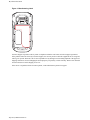
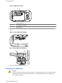
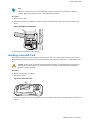
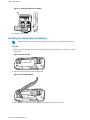
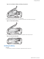
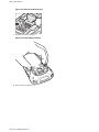

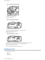

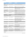

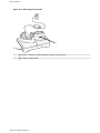
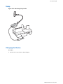
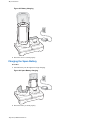
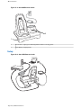
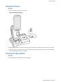
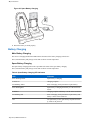
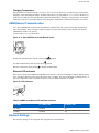
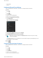
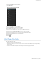
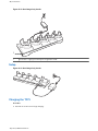
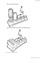
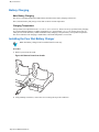
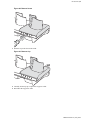
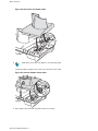
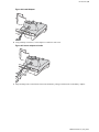
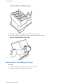
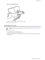
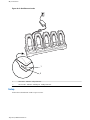
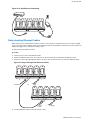
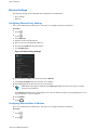
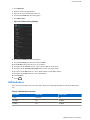
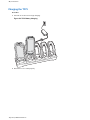
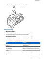
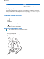
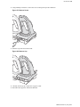

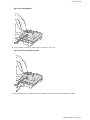
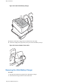
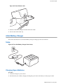
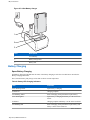
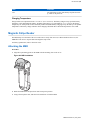
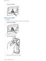
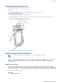
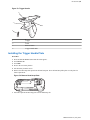
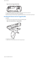
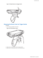
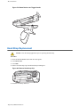
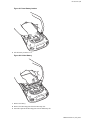
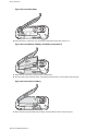


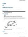
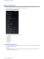
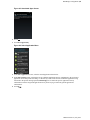
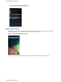
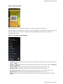
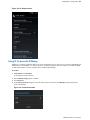

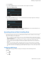
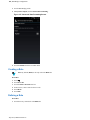
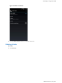
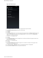
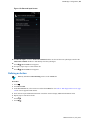
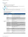
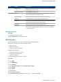
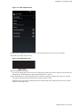
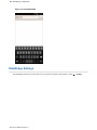
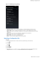
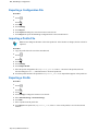
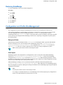
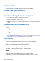


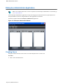
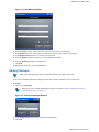
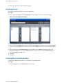

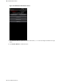
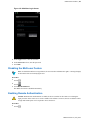
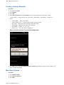

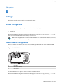
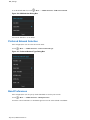
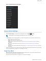
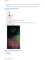
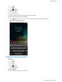
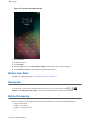
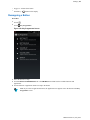
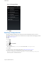


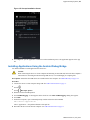

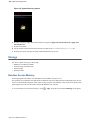
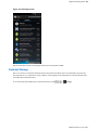
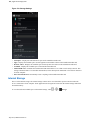
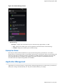

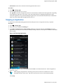
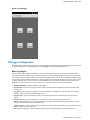


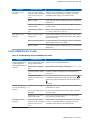
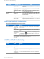
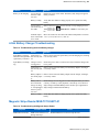


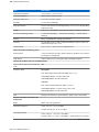
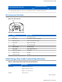

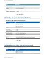
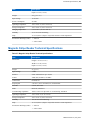
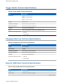
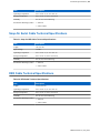
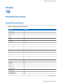
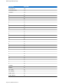
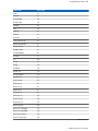


![MC45 User Guide [Italian] P/N# 72E-164159-01IT Rev. B](http://vs1.manualzilla.com/store/data/006159142_1-09ba44b15b8f4b34bd375cd37a9ecc8f-150x150.png)
![MC32N0 Regulatory Guide [English] (P/N MN000216A02 Rev. B)](http://vs1.manualzilla.com/store/data/006085477_1-e8060af26a8d96f286d08f3a460ea342-150x150.png)