1
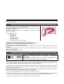
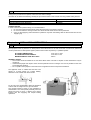
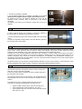
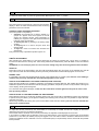
Air Jet Sieve
SV016
Impact Test Equipment Ltd
www.impact-test.co.uk & www.impact-test.com
User Guide
User Guide
Impact Test Equipment Ltd.
Building 21 Stevenston Ind. Est.
Stevenston
Ayrshire
KA20 3LR
T: 01294 602626
F: 01294 461168
E: [email protected]
Test Equipment Web Site
www.impact-test.co.uk
Test Sieves & Accessories Web Site
www.impact-test.com
User Guide
User Guide
DO NOT ATTEMPT TO OPERATE THIS EQUIPMENT BEFORE READING AND
COMPREHENDING THE MANUAL IN ALL ITS PARTS
USERS
•
•
•
•
•
MACHINE MANUFACTURERS
DRAUGHTSMEN
OPERATORS
MAINTENANCE WORKERS
ANY OTHERS
BEFORE USING THE ASPIRATOR SUPPLIED WITH THE SIEVE SHAKER, CHECK
THAT THE PAPER AIR FILTER HAS BEEN TAKEN OUT FROM THE ASPIRATOR; IF
IT IS STILL PRESENT, REMOVE IT.
WARNING
BEFORE USING THE APPLIANCE, READ THE CHAPTER “SUGGESTIONS FOR THE
ASPIRATOR USAGE” AND CONSULT THE OPERATING INSTRUCTIONS OF THE
ASPIRATOR.
CONTENTS
Chapter 1
1.01
1.02
1.03
1.04
1.05
1.06
1.07
1.08
1.09
1.10
1.11
Chapter 2
2.01
2.02
2.03
2.04
Chapter 3
3.01
3.02
3.03
Chapter 4
4.01
4.02
Chapter 5
5.01
5.02
5.03
5.04
5.05
5.06
5.07
5.08
5.09
5.10
5.11
5.12
5.13
Chapter 6
6.01
6.02
6.03
GENERAL INFORMATION
Warnings
WARNING and DANGER indications - SIGNS
Aim of the Instructions Manual
Modifications and enclosures of the Instructions Manual
N/A
EC Stamp
Usage
Operators
Storage
Transportation and Movement
Packaging removal
TECHNICAL CHARACTERISTICS
General machine description
Dimension and weight
Electrical supply
Noise
GENERAL SAFETY NORMS
General norms
Machine Safety devices and protection
Dangerous parts and residual risks
INSTALLATION INSTRUCTIONS
Location
Electrical connection
IN FUNCTION - USE
Set up
How to connect the aspirator to the sieve- shaker
Machine calibration – Meters - Indicators
How to place the material to be sieved
Switching the equipment on
Control panel adjustment
Vacuum adjustment
Emergency stop
Start up after emergency
Switching off
Test Start Up
Suggestion for the aspirator usage
Practical example of usage
MAINTENANCE
Ordinary Maintenance
Extraordinary Maintenance
Authorised maintenance centres
Chapter 7
GUIDE TO RECOGNISING DAMAGE AND ANOMALIES
Chapter 8
SPARE PARTS
Chapter 9
INACTIVITY
Chapter 10
DECOMMISSIONING THE MACHINE
Chapter 1
GENERAL INFORMATION
1.01 WARNINGS
The manufacturer does not accept any responsibility for direct or indirect damage to people, things or animals and use
of the appliance in different conditions from those foreseen.
The manufacturer reserves the right to make changes to the documentary information or to the appliance without
advance notice.
Check the machine responds to the standards in force in the state in which it has been installed.
All operations necessary for maintaining machine efficiency before and throughout use are the operator’s responsibility
Carefully read the entire manual before operating the machine.
It is vital to know the information and limitations contained in this manual for correct machine use by the operator.
Interventions are only permitted if the operator is accordingly competent and trained.
The operator must be knowledgeable about machine operations and mechanisms.
The purchaser must ensure that operators are trained and aware of all the information and clarifications in the supplied
documentation.
Even with such certainty the operator or user must be informed and therefore aware of potential risks when operating
the machine.
Safety, reliability and optimum performance is guaranteed when using original parts.
Any tampering or modifying of the appliance (electrical, mechanical or other) which has not been previously authorised
in writing by the manufacturer is considered abusive and disclaims the constructor from any responsibility for any
resulting damage.
All necessary operations to maintain the efficiency of the machine before and throughout use are the responsibility of
the user.
1.02 WARNING AND DANGER INDICATIONS - SIGNS
The machine has been designed and constructed according to the current norms and consequently with mechanical
and electrical safety devices designed to protect the operator or user from possible physical damage. Residual risks
during use or in some intervention procedures on the device are however present. Such risks can be reduced by
carefully following manual procedures, using the suggested individual protection devices and respecting the legal and
safety norms in force.
This manual includes “Warning” and “Danger” indications in relevant chapters. These indications are shown with the
words “Danger” or “Warning” in bold font and uppercase to make them highly visible.
“WARNING” indicates that machine damage could be caused should indications be ignored.
“DANGER” indicates that machine damage and/or injury to the worker could be caused should indications be ignored.
“DANGEROUS ZONE” indicates any zone inside or in the proximity of the appliance in which a person is exposed to the
risk of injury or damage to health.
1.03 AIM OF THE INSTRUCTIONS MANUAL
This manual has been edited with the aim of providing all machine operators with all the necessary information on
installation, use and maintenance from production to scrapping in as comprehensive and clear manner as possible.
All the procedures useful for any foreseeable emergency situations have been listed by the manufacturer and can be
verified during use.
Operators, for whom this manual has been written, due to their competence must give instructions or operate the
machine themselves.
The instructions manual must be carefully consulted by laboratory or site safety managers, equipment operators and
any internal and external maintenance workers.
The manual is integral to the product and refers to this appliance only.
The manual must be safeguarded and always kept near the equipment so that it can be easily consulted whenever
necessary.
IMPORTANT: The manual does not substitute the experience and technical training of the worker but must be
considered a guide for carrying out its functions.
Furthermore all the norms and rules the operator should be aware of or consult for correct use of the machine and/or
test performance can be found in the manual.
This responsibility is entrusted to the installer and Laboratory or Site Manager where the machine is installed.
The Constructor is available to provide further information.
1.04 MODIFICATIONS AND ENCLOSURES OF THE INSTRUCTIONS MANUAL
This manual reflects the state at the time of the launch of the machine on its market. If any modifications, improvements
or adjustments have been made since machine supply the Manufacturer does not have to intervene on the marketed
machine and will not consider the machine or the manual deficient or inadequate.
1.06 EC STAMP
SEE EC DECLARATION
1.07 USAGE
The air jet machine is used for sieving powder and dry grain products by
obtaining sieving results between 5 to 4000 microns.
Its working foundation is based on the use of air that tug thin particles to make
them go through the sieve.
This effect is made through a vacuum machine that provokes a controlled
decrease of pressure.
STANDARD EQUIPMENT
•
Sieve shaker
•
Supplying cable
•
Plexiglass cover
•
Little plastic hammer
•
Instructions manual
•
Vacuum cleaner and connection pipe
This appliance is for the exclusive use which it has been conceived for.
Any other use is considered improper and therefore negligent.
Machine use is allowed only in places free from danger of explosion or fire.
During operation check for conditions of danger.
immediately stop the machine should it be working irregularly, and consult the authorised dealer’s Sales Service
department.
It is the Client’s responsibility to verify at the time of installation and use that no conditions of use arise which are
different to those indicated.
Refer to the Constructor when in doubt.
1.08 OPERATORS
DANGER
WARNING
The use, transportation, installation, maintenance, demolition and
disposal of the appliance are only permitted to “QUALIFIED
PERSONNEL”.
This manual is exclusively aimed at “QUALIFIED PERSONNEL” and
contains the necessary information for machine use.
”QUALIFIED PERSONNEL” means people who, due to their training, experience and education, as well as knowledge
of the relevant standards, limitations and measures, have been authorised by the “PLANT SAFETY MANAGER” to carry
out any necessary activity and are able to recognise and avoid any possible danger.
The manufacturer recommends that the instructions, procedures and recommendations in this manual and the work
safety legislation in force be scrupulously adhered to, even with the use of appropriate protection devices (whether
individual or part of the machine).
Knowledge and respect of the instructions, safety warnings and danger in this manual are all necessary for installation,
operation, management and machine maintenance with a minimal risk.
The “PLANT SAFETY MANAGER” has the following responsibilities and duties:
- To know the machine functions, its commands, safety and protection devices, possible dangers of use and all the
information in this manual in detail. This knowledge can only be gleaned from detailed reading of this manual.
- To know the safety legislation in force in detail in order to operate the machine
- To recognise the “QUALIFIED PERSONNEL” for transportation, handling, installation, use, maintenance, disposal, etc.
- Correctly train and educate the “QUALIFIED PERSONNEL” before allowing them access to the machine.
personnel must also be exhaustively trained with regards to the machine’s protection devices.
The
- Ensure the machine’s safety devices are not tampered with or removed and are checked on a daily basis. Provide the
operator appropriate individual protection devices according to the laws in force.
- The constructor is available for clarification, assistance and training and declines all responsibility for damage to things
or people resulting from improper, incorrect and negligent use by untrained personnel.
1.09 STORAGE
WARNING
The appliance must be stored and conserved in the original packaging and in a closed
environment, protected from atmospheric agents with a minimum temperature of -15C°,
and a maximum of +60C° and a maximum humidity of 70 %.
1.10 TRANSPORTATION AND MOVEMENT
WARNING
In order to avoid irreparable machine damage, move with care, do not overturn, protect
from rain, do not stack, protect the packaging and its contents from bumps and sources of
heat.
During transportation and movement it is important to avoid bumps, overloading with other packages, exposure to
freezing or heating atmospheric agents, or any other potentially harmful condition to the device, things or people.
Machine transportation and movement must be entrusted to Qualified Personnel who can ensure correct movement.
DANGER
WARNING
Do not transport or move the product should it be impossible to respect the
conditions on the packaging or there be any doubts. Request information from
the constructor.
1.11 PACKAGING REMOVAL
After removing the packaging check the machine is complete and that there are no visibly damaged parts. DO NOT
USE THE MACHINE and refer to the constructor when in doubt.
DANGER
The components used for packaging (plastic bags, polystyrene, nails, screws, wood, etc)
must be kept out of reach of children, as they are sources of danger. These components
should be placed in the appropriate containers.
WARNING
In order to avoid bumps and overturn adopt the normal and logical precautions. Before
disposing of the packaging check all machine components such as accessories, utensils,
instructions, documents etc have been removed.
Chapter 2
TECHNICAL CHARACTERISTICS
2.01 GENERAL MACHINE DESCRIPTION
LID A1
It is used to seal the sieve A2 and the material that have to
be sieved during the test in order to avoid material’s outflow.
SIEVE A2 (it’s an accessory not supplied with the
instrument).
GENERAL SWITCH A3
The switch enables or disables all the sieving-shaker
functions, including the aspirator functioning.
Next to the general switch there is the supplying voltage tap
with the appropriate connection cable supplied with the
equipment.
ELECTRIC TAP FOR ASPIRATOR A4
Tap to which is connected the electric supplying of the
aspirator.
MOUTH PIECE OF THE ASPIRATOR PIPE A5
The aspirator pipe is connected to this mouth piece; the
aspirator is used to create the vacuum
REGULATION COUPLING OF THE VACUUM A6
After starting the aspirator, it is possible to increase or
decrease the generated vacuum degree by screwing and
unscrewing this regulator device.
2.02 DIMENSION AND WEIGHT
LENGTH
WIDTH
HEIGHT
WEIGHT
430 mm
407 mm
340 mm
20kg circa
2.03 ELECTRICAL SUPPLY
VOLTAGE
PHASE NUMBERS
FREQUENCY
SIEVING MACHINE POWER
ASPIRATOR POWER
230 V
1
50Hz
100 WATT
1300W
2.04 NOISE
The air noise emission levels shown do not necessarily imply the levels of exposure to the worker.
The levels of exposure to the operator are obviously linked to the emission levels of the appliance; however other
factors influence the levels of exposure to the operator: length of exposure, environmental characteristics, the presence
of other machines etc.
The appliance emission levels allow anyway an estimate to be carried out on the dangers due to noise.
DANGER
Continuous use of the appliance and machines predictably present in the
installation environment could cause a heightened daily personal exposure to
noise.
If the daily personal exposure is equal to or more than 85 dB (A) it is advisable to use the Individual Protection Devices
(protective headphones, plugs, etc.). If the daily personal exposure is equal to or more than 90 dB (A) it is compulsory to
use Individual Protection Devices (protective headphones, plugs, etc.). For further information consult the standards in
force in the country of installation.
Average continuous equivalent acoustic pressure level Laeq to the distance 1.5 m 61 (A):
Level of acoustic power emitted by the LWA device xx dB (A):
Standard EN ISO 3746
Chapter 3
GENERAL SAFETY STANDARDS
3.01 GENERAL STANDARDS
To ensure the safety of machine operators:
· Any tampering with the appliance not pre-emptively authorised by the manufacturer exempts the manufacturer from
any responsibility for damage caused by or to it.
· The removal or tampering with safety devices entails a violation of the safety standards.
· Machine use is only allowed in areas where there is no risk of explosions or fires.
· Only the original fittings can be used. The use of unoriginal fittings exonerates the manufacturer from all
responsibility.
• Check the appliance is in ideal working conditions and that its parts are not worn or faulty before Carry out all
necessary maintenance
• Do not wear loose clothing, ties, chains or anything else which could become caught in the frame or other moving
parts of the appliance.
• Be aware of the danger of electrical shocks from direct or indirect contact due to unforeseen electrical faults.
• Do not subject the appliance to violent impact.
• Do not expose the appliance to fire, welding sparks or extreme temperatures.
• Do not bring the appliance into contact with corrosive substances.
• Do not wash the appliance with jets of water.
· Check the workspace around the machine is clear from potentially dangerous objects.
· The machine operator must wear appropriate work clothing such as protective glasses, gloves and mask in order to
avoid damage from, for example, harmful dust projection. Wear a lower back support when lifting heavy parts. There
should be no hanging objects such as bracelets or otherwise, long hair should be protected with relevant precautions,
shoes must be appropriate for the type of operation to be carried out.
DURING USE
When operating check there are no conditions of danger. Immediately stop the machine when it is functioning
irregularly. Contact the authorised Sales Service department.
• For the operator’s safety do not touch any part of the appliance when testing and use the appropriate individual
protection devices in order to keep the operator safe.
3.02 MACHINE SAFETY DEVICES AND PROTECTION
DEFINITION: Protections are all the safety measures that consist of the use of specific technical means (repairs, safety
devices) to protect people from dangers which cannot be limited reasonably in design.
DANGER
Tampering with the protections or any appliance modification could cause risks to users or
other exposed people.
The manufacturer does not assume any responsibility for direct or in direct damage to
people, things or animals following tampering with the protections.
The sieving machine is provided with a general switch A3, that works also as emergency switch.
3.03 DANGEROUS PARTS AND RESIDUAL RISK
During some procedures the operator could face some risks of danger.
The risks can be eliminated following carefully the procedures written in this manual and using suitable safety devices
RISK OR DANGER
FINGER SQUEEZE
LOSS OF GRANULATED MATERIAL
PROTECTION DEVICE
REINFORCED GLOVES
GLASSES
DURING THE USE
In order to assure the operator safety, it is recommended to:
1. Do not remove the lid and the sieve during the functioning of the sieving machine
2. Do not ever switch the sieving machine on if the lid and the sieve have not been positioned
3. Carry out the equipping and maintenance operations only when the feeding cable is disconnected from its own
supplying tap.
Chapter 4
INSTALLATION INSTRUCTIONS
4.01 LOCATION
The equipment must be placed in an ideal position and environment for the use it has been conceived for (laboratory
use and protected from atmospheric agents) and that the machine is placed by a qualified operator.
ALLOWED TEMPERATURE:
ALLOWED RELATIVE HUMIDITY:
MAXIMUM HEIGHT OVER SEA LEVEL:
from +5°C to +40°C
from 30% to 70%
1000 m
GENERAL ADVICE
• The machine must be installed in an area which allows ease of access to all parts so that maintenance may be
carried out.
• Unauthorised people and objects which could be potential sources of danger must not be permitted in the area
surrounding the machine.
• Do not position the equipment near instruments or appliances which could produce vibrations.
The appliance rests on rubber feet and had to be
placed on a plane surface for a better stability,
otherwise it may capsize and cause injuries.
For an easy use it is advisable to place the appliance
at about 700 mm height from the ground surface.
The required minimum space for the installation is
430x407x340. The control panel preferably has to be
placed and fixed at such a distance that doesn’t
interfere with the equipping and sample loading
operations.
4.02 ELECTRICAL CONNECTION
DANGER
Wiring of the electrical system must be carried out by qualified personnel.
Before wiring consult the electric plan linked to the instructions manual and the
registration plate on the machine for information regarding supply, frequency and nominal
current.
Connect the earthing system via the PE terminal (yellow-green) before any other
connection.
Apply a knife switch at the top of the connecting cable of the machine to the power
system.
The knife switch must be combined with a safety device against the overload with a
differential switch (safety switch).
The technical features of the safety device must be in accordance with the standards in
force in the country where the machine has been installed.
ELECTRIC TOLERANCES:
•
•
•
•
•
•
•
Real voltage ± 10 % of the nominal one
Frequency:
± 1 % of the nominal one in a continuous way
± 2 % of the nominal one for a short period
The harmonic distortion of the sum from the second to the fifth harmonics not more than 10 % of the total voltage as
a real value between the conductors. A further distortion of 2% is accepted for the sum from the sixth to the thirtieth
harmonics of the real total value between the conductors.
With reference to the voltage imbalance of the three-phase voltage, the inverted sequence component and the zero
sequence component must not be more than 2% of the direct sequence component of the voltage.
The voltage pulses must not last more than 1,5 ms with an up/down time between 500 ms and 500 ms and a peak
value not higher than 200 % of the real value of the nominal tension.
The electric supply must not be interrupted or zeroed for more than 3 ms at any time. Between two interruptions it
must not take more than 1 s.
The interruptions must not overcome 20 % of the tension peak for more than one cycle. Between two interruptions it
must not take more than 1 s.
The manufacturer assumes no liability for any damages to people, things and animals caused by the non-compliance of
the above instructions
Chapter 5
IN FUNCTION - USE
DANGER
WARNING
Before setting the machine in motion it is essential that the Operator and Safety
Manager have read the Instructions Manual and understood all parts of the
machine and activities linked to it (Risks, Dangers, Functionality, Operation,
Protections, Commands, etc.)
5.01 SET UP
Before using the appliance, check that the distance between the sieve
bottom and the aspirator mouth is between 2 and 4 mm; this distance
has been already checked in the factory during the production phase.
It is suggested to make a periodical inspection, especially if several
types of sieves are used, by following these instructions:
1. Unscrew the aspirator mouth B3
2. The rod B2 is supplied with a regulation screw B1 on its end that
determines the aspirator mouth’s height compared to the sieve.
By tightening the screw the distance between the sieve and the
aspirator’s mouth increases, while by unscrewing it the distance
decreases.
ATTENTION: the opening of the aspirator’s mouth have to be free of
deposits.
5.02 HOW TO CONNECT THE ASPIRATOR TO THE SIEVE- SHAKER
In order to start the sieving it is necessary to connect the aspirator to
the sieve shaker as explained in the following instructions:
• connect the aspirator’s pipe to the mouth piece A5 of the sieve shaker
(pic.3).
• connect the aspirator’s feeding cable to the input A4 that is placed on
the back side of the sieve shaker.
5.03 MACHINE CALIBRATION – METERS - INDICATORS
The machine is checked in the factory, using sample equipment periodically checked by officially recognised institutes.
These checks cannot guarantee that the machine, meters and indicators will provide accurate values and results
conforming to the standards in force in the countries the machine has been installed and used in.
Normally such norms envisage calibration check after every movement. In order to obtain correct values and results it
is therefore VITAL that the operator, once the machine has been installed and set up and before official tests, has an
officially recognised body check the machine characteristics, its calibration and results/values reliability. The
manufacturer is exempt from all responsibility in the case of direct and indirect damage from use of the machine without
officially approval by the relevant bodies.
As explained before, the sieve shaker is supplied already calibrated; in case it was necessary or it was required to check
that the visualized vacuum value is correct, you have to contact the technical assistance service.
5.04 HOW TO PLACE THE MATERIAL TO BE SIEVED
The material which have to be sieved must be put in the upper sieve;
after that, cover the sieve with the lid A1.
If there is an high quantity of material, the sieving will take longer and
the test will be more accurate.
The maximum material size must be checked. The material (that must
be granulated) have to move on the sieve when the aspirator mouth is
working.
The weight have to be in compliance with the kind of test to be
executed. Our general recommendations for Ø 200 mm are:
•
•
•
Normal condition. Sieves with a 0,040 mm opening: 20 gr.
Heavy materials with good smoothness: up to 50 gr.
Light materials hard to be sieved and sieves with opening less
than 0,040 mm: 10gr.
5.05 SWITCHING THE EQUIPMENT ON
To switch the sieve shaker on press the general switch A3 and place it on the ‘’I’’ position.
5.06 CONTROL PANEL ADJUSTMENT
The control panel is composed by 4 keys and one luminous
display; it allows to select and visualize the main functioning
parameters of the sieve shaker.
CONTROL PANEL OPERATING FEATURES
The control panel is composed by:
A display C1 composed by 4 figures, divided in 2
groups of 2 figures each; the 2 figures on the left
shows the reached vacuum value (expressed in
millibar), the 2 figures on the right shows the selected
total time of the sieve-shaking.
A starting key C2: by pressing it the sieving starts
working.
A stop key C3: it is used to stop the timer and
sieving phase.
2 keys C4: used to increase and decrease the
sieving time
Every time that a key is pressed a bip will be given out.
TIMER’S ADJUSTEMENT
After switching the sieve-shaker on and before beginning the sieving by pressing the 2 keys C4, it is possible to
increase and decrease the sieving time. After having selected the desired time, press C2 once to save the selected
value.
ATTENTION: it is necessary to press C2 once to save the setting every time the sieving time has been modified.
START-UP
Press C2 to start-up the sieve-shaking; the timer will automatically begin the count-down of the selected time and will
stop at the end; when the sieve-shaking ends the previously selected time will automatically appear on the screen.
NORMAL STOP
It is possible to stop the sieve-shaking before the end of the selected time, by pressing C3; when the sieve-shaking is
restarted, the previously selected time will automatically appear on the screen
HOW TO STOP MOMENTARILY THE SIEVE SHAKING (PAUSE FUNCTION)
During the sieve-shaking it is possible to suspend it momentarily by pressing C2 once: that enables the operator to run
settlement operations of the material as well as equipping operations; the pause is pointed out by the flash of the figures
on the display, showing the missing time.
To re-start the sieving press C2 again; in this case the count-down will start again from the point in which it had
been previously stopped.
HOW TO RE-SET UP THE TIMER DURING THE SIEVE-SHAKING
Press C2 During the test to modify the remaining sieving time; the sieving will be immediately stopped; the suspension
is pointed out by the flashing of the figures indicating the remaining time; at this point it is possible to adjust the timer
using the 2 keys C4.
After having reselected the sieving time, press 2 times C2 to restart the sieve shaking (once to save the selected time
and once to re-start the test).
5.07 VACUUM ADJUSTMENT
To adjust the vacuum produced by the sieve-shaker, it is necessary to roll A6; unscrew the coupling to reduce the
depression and screw it to increase the depression.
The increase and the decrease of the vacuum produced by the aspirator will be displayed on the screen.
In accordance to UNE-EN 933-10 Standard “Test for the determination of arid geometric properties” the recommended
pressure is 3,0 ±0,5 kPa (-30 millibar). Anyway we suggest to run more tests in order to be able to determine the correct
pressure for different kinds of materials. The too soft materials (easy to be pulverized) must be sieved with the possible
lowest pressure.
5.08 EMERGENCY STOP
In case of emergency it is possible to stop the sieve-shaker by pushing the general switch A3 and by placing it on 0
position.
5.09 START UP AFTER EMERGENCY
WARNING
DANGER
Before re-starting the appliance determine and eliminate the causes of
the emergency stop
To re-start the sieve-shaker push the general switch A3 and place it on ‘’I’’.
5.10 SWITCHING OFF
Press C3 to stop the sieving machine
5.11 TEST START UP
Before using the appliance regularly check it is working correctly by carrying out at least one complete empty cycle
according to the previous instructions.
Should there be any problem consult the chapter “DIAGNOSTICS”.
If the instructions in this manual do not provide the solution to the problem, contact Sales Assistance.
5.12 SUGGESTIONS FOR THE ASPIRATOR USAGE
Some suggestions are listed as follows; they allow the operator to use the aspirator correctly:
Remove or do not assemble the paper filter on the aspirator in order to use it correctly, but leave the plastic
bag.
During the test, every time that the vacuum created by the aspirator is not enough to satisfy the requirements
declared by the Standard, activate the control of the filter cartridge automatic cleaning (the aspirator’s filter
cartridge could be dirty); in this way the aspirator will work at its maximum potentialities.
If the vacuum created by the aspirator will not be enough even after the filter cleaning operation, it is necessary
to replace the filter cartridge placed in the sieve shaker. Consult the instructions enclosed to the aspirator in
order to replace the cartridge filter of the sieve shaker.
WARNING
NEVER SUCK IN WITHOUT THE CARTRIDGE FILTER
5.13 PRACTICAL EXAMPLE OF USAGE
Hereunder we describe a “ standard-procedure” which allows even to an operator without a wide experience to carry out
a test.
Naturally the operator experience will allow to optimise the machine performances on the basis of the customer needs
In order to have several points in the grinding material curve, start the test with the sieve with smaller openings and
sieve the material that has not been passed through the sieve with larger openings. Follow the same procedure using
other openings and repeat it depending on how many divisions the operator would like to obtain.
The hygroscopic products absorb the humidity of the air during the sieving procedure. This could be the reason of some
measuring mistakes.
To avoid this kind of mistakes it is suggested to dry the material before and after every test.
DANGER
Do not attempt to use this machine without reading and fully understanding this manual in
all parts.
WARNING
1.
2.
3.
4.
5.
6.
7.
8.
9.
Chapter 6
Do not assemble the paper filter but only the plastic bag for a correct use of the
aspirator.
Check the distance between the sieve and the aspirator mouth as described in chapter “SET UP”
Position the material to be sieved as described in chapter ‘’HOW TO PLACE THE MATERIAL TO BE
SIEVED”
Connect the aspirator to the sieve shaker as explained in chapter ‘’HOW TO CONNECT THE ASPIRATOR
TO THE SIEVE- SHAKER”
Switch the sieve-shaker on by pressing the general switch A3.
Adjust the timer as described in chapter “TIMER’S ADJUSTMENT’’. In accordance to the UNE-EN 933-10
Standard, 2001 edition, the sieve shaking time can be considered concluded when the weight does not
change more than 0,1% in one minute.
Start the instrument by pressing C2
During the sieve-shaking process it is advisable to hit the cover with the plastic hammer to remove the
dust of the material. It is possible to stop the machine under vacuum and the air sieve-shaker to remove
with a brush the residual materials that may have produced.
Wait or the end of the sieve-shaking time selected on the timer, when the time is expired the sieving will
stop (to stop the test before the selected time press C3).
When the sieving ends, it is necessary to weigh the material that is still on the sieve. To avoid loss of
material, brush the inner surface of the cover and brush accurately the openings when the pulverized
granules are put on another sieve.
MAINTENANCE
6.01 ORDINARY MAINTENANCE
WARNING
DANGER
Do not perform maintenance – interventions on the machine which have not
been quoted and described in this instructions manual without first contacting
the manufacturer.
Periodically clean all machine parts and oil the unpainted parts in order to
preserve the machine and its efficiency.
Avoid the use of solvents which damage paint and parts in synthetic material.
How to clean the sieve-shaker:
•
To remove the aspirator’s mouth, pull it upwards.
•
Connect the sieve-shaker and clean the aspirator’s mouth with a brush and the sieve- shaker’s body and its
inner part with a vacuum cleaner.
ATTENTION: do not turn the aspirator’s mouth B3 with hands
How to clean the aspirator:
Consult the chapter “SUGGESTIONS FOR THE ASPIRATOR USAGE” for the aspirator cleaning operations.
How to clean the sieves:
Clean carefully the lower part of the sieve with a soft brush. Do not push and do not hit the sieve’s mesh.
The most efficient way to clean the sieves is an ultrasonic cleaner. An ultrasonic cleaner is the fittest for this use. To
increase the effectiveness of the cleaner, use a water detergent.
6.02 EXTRAORDINARY MAINTENANCE
For extraordinary maintenance operations refer directly to the Manufacturer.
6.03 AUTHORISED MAINTENANCE CENTRES
For information on the nearest authorised help centre it is essential to contact the manufacturer.
Chapter 7
GUIDE TO RECOGNISING DAMAGE AND ANOMALIES
This chapter presents and discusses all the simple problems which could occur during machine use.
The appropriately qualified, professional personnel must carry out all the maintenance procedures, check and control,
as well as all the repair operations on parts of the machine or the electrical system.
Contact Technical Sales Assistance for any other problem not listed on the previous table or should the malfunctioning
persist after the intervention of the operator in accordance with the previously mentioned courses of action.
PROBLEM
POSSIBLE CAUSE
Fuses are broken
When pressing A3 the control panel does Lack of supply
not switch on
When pressing A3 the control panel Damage in the electric system
switches on but the aspirator’s mouth does
not turn.
Ratiomotor malfunctioning
It is not possible to reach the vacuum value Damage of the vacuum sensor
as required by the Standard
Blow-by from the suction
equipment
The aspirator does not work
properly
Chapter 8
REMEDY
Replace them
Check the connection to the power
grid
Check the electric system
Ratiomotor replacement
Replace the sensor
Find the 3 filaments and remove
them
Clean the filters; look at the
“SUGGESTIONS FOR THE
ASPIRATOR USAGE” chapter.
SPARE PARTS
WARNING
DANGER
Only original spare parts can be used.
Use of unoriginal spare parts exempts the manufacturer from all
responsibility. Procedures for substitution of spare parts will be provided
by the manufacturer along with the part. For spare parts contact the
manufacturer’s Sales Service department.
.
SIEVE A058-12:
Sieve Ø200mm, stainless steel frame and nylon cloth , openings from 5 to 71 microns ( when ordering please specify
cloth opening).
SIEVE A058-13:
Sieve Ø200mm, stainless steel frame and cloth, openings from 75 to 4000 microns ( when ordering please specify cloth
opening).
FILTER CARTRIDGE A058-14:
Spare part for the aspirator filter cartridge replacement.
PLASTIC BAGS A058-15:
Spare part : pack of 5 pieces.
Chapter 9
INACTIVITY
Ensure all machine parts are in safe working order before operating it again should the machine be inactive for a long
period of time. When in doubt contact the Manufacturer
Chapter 10
DECOMMISSIONING THE MACHINE
Should it be decided that the machine is to be no longer used, proceed as follows:
• Disconnect the electrical supply network by removing the connecting cable therefore making it unusable.
• Make the potential sources of danger harmless, such as sharp or protruding parts.
• Dismantle the machine; divide it into similar parts and dispose of according to the standards in force.
Recycling notice for the disposal of electrical and electronical devices
This symbol, shown on the device or on the package and/or the documentation, suggests that the device
should not be disposed together with other home garbage at the end of its life cycle.
To avoid further environment, or health-care damage, caused by the unsuitable disposal of garbage, the
user should separate this device from other different types of garbage and recycle it in responsibly to
avoid the reuse of material resources. Users must take care at the disposal of the equipment by taking it
to the nearest recycling site for appropriate recycling treatment for electrical and electronical devices. Gathering and
Recycling deplete devices allow the preservation of natural resources and grant them the adequate treatment by
respecting health and environment.
For further information on your local recycling site please contact your local council or city waste treatment department.
The developer, as producer of electrical and electronical devices, will provide to finance the recycling and treatment
services for deplete devices that will come back through these recycling sites, according to the local statement.