1
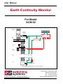
User Manual
Earth Continuity Monitor
For Model
GCM-52
Leaders in :
switching
systems
Voltage-Dip Proofing
ELECTRONIC ENGINEERS
Earth Continuity Monitoring
User Manual
Contents
Introduction ..................................................................................................... 3
Theory of operation ......................................................................................... 3
Description ...................................................................................................... 4
Front panel controls ......................................................................................... 5
Operation......................................................................................................... 5
Relay truth table .............................................................................................. 9
Specifications & Ordering .............................................................................. 10
Installation guide ........................................................................................... 11
Test schedule ................................................................................................ 11
Mechanical outlines & connections ............................................................... 13
Page 2
GCM-52
User Manual
Introduction
Earth leakage relays perform two main functions on mining installations: to protect machinery
from damage and to make the installation safer for personnel. In the typical distribution circuit
shown in Fig 1, an earth leakage relay provides protection against leakage to earth and earth
faults. The principle of this method is that all the current flowing to the load must return from the
load. If current leaks to the frame of the motor and returns via the earth bond back to the star point
of the supply transformer then this difference is detected by the earth leakage relay which triggers
the breaker, thus disconnecting the load.
It becomes apparent that the earthing must be solid and reliable for electrical installations to be
safe. For this reason, machinery is earthed via the supply cable,
using either a copper conductor of the cable or the armour. The
Supply
ground on which the machinery stands is normally not considered a
Transformer
reliable earth. Mechanical damage to the earth bond, corrosion of the
armour or bad workmanship may result in a high resistance point in
Main Earth
the earth return. If an earth fault occurs, voltage will be developed
across the high resistance region. This voltage poses a potential
Neutral
Earthing
hazard to any personel who may be exposed to it. Depending on the
Resistor
resistance value, the current flowing and the reaction time of the earth
leakage relay, this could be fatal. It is obvious that continuous Bus
monitoring of the earth bond is imperative if safety standards are to Bars
be maintained.
Q1
Breaker
I>
Theory of operation
To continuouslymonitor the resistance of the earth bond, an electrical
measuring signal is fed into the earth conductor via a separate pilot
wire. To cater for the possibility of a short between this pilot and the
earth, a remote module must be employed.
A loop now exists, consisting of the pilot wire, the remote
module and the earth wire in the cable. An intrinsically safe signal is
injected into the loop and, by interpreting the voltage and the current
flowing, the resistance can be monitored: see Fig 2. The energy level
of an intrinsically safe signal is so low that dangerous gases like
hydrogen or methane cannot be ignited by it.
Depending on factors such as the length of the supply cable,
the nature of the load, variable speed drives or heavy load switching,
and the location of the installation, [near a pipeline with cathodic
protection or a DC railway line], a range of noise signals can be
induced or injected into the loop: the signals can vary from high
frequency generated by thyristor switching, to 50Hz and DC. Noise
signals can have an amplitude of up to 100V. The relatively low level
of the intrinsically safe measuring signal and the high electrical noise
necessitated the development of specialised measuring circuitry.
GCM-52
I>
E
I>
L
Earth
Leakage
K1
Contactor
with
Overload
Cable
Earth
SWITCHING SYSTEMS' range of EARTH CONTINUITY
RELAYS provides a cost effective solution to the problem.
Load
Main
Earth
Fig1
A typical distribution
circuit
Page 3
User Manual
Description
The earth continuity monitoring system consists of a
monitor, remote module and monitor protection filter. Monitors are available in two types of enclosure as described
below.
Voltage
Main 7A
Earth
Earth Continuity Monitor
Neutral
Earthing
Resistor
Bus
Bars
Q1
2B
1B
3
2
Breaker
I>
I>
E
I>
L
Earth
Leakage
The Remote Module consists of a 100Ω, 1% 30 watt
calibrated resistor, terminated with a M12 and M8 brass
bolt, for connection to Earth and Pilot respectively. For
physical dimensions see Fig 9 on page 14.
Cable
Earth
1
Pilot M8
The Protection Filter prevents damage to the monitor
due to phase to earth and phase to pilot faults. The monitor
filter can continuously withstand faults on restricted neutral
systems up to 300A without damage to the filter or monitor.
It is recommended that a protection filter should be purchased together with a new GCM monitor and consideration
should be given to installing a protection filter to to protect
the monitor in existing installations. Electrical & mechanical
specifications appear on pages 7 & 10 respectively.
8A
GCM-PF1
Protection
Filter
The external connections consist of two terminals for
the supply voltage, three terminals each for the two potential
free change over contacts; plug “A” and one each for the
pilot and earth connections; plug “B”. The truth table for the
operation of the two changeover contacts is shown in Fig 5.
This configuration was chosen to provide a “no power on
unit” indication. The dimensions and connection diagram
are shown in Fig 7 on page 13.
Control
Pilot
The GCM-52 monitor is mounted in a compact plastic
case and is connected via two Molex plugs. This is the
preferred model for all new installations. A typical application
circuit is shown in Fig 2.
Supply
Transformer
Main
Earth
Remote
Module
Load
Earth M12
Fig 2
Earth Continuity Monitor
Connection Diagram
Page 4
GCM-52
User Manual
Front panel controls
The GCM-52 front panel is shown below together with descriptions of the controls and
control functions.
switching
systems
ELECTRONIC ENGINEERS
LCD Display
2 x 12
Earth Continuity Monitor
GCM-52
Up
Next key Navigate to the various menus and
select the digit to be adjusted.
Next
Intrinsic Safety / Intrinsieke
Veiligheid
[Ex ib] I / IIC
MS / 03-483X
Up key Adjust the selected digit value, press
once to increment by 1, press & hold
to cycle through all digit values (0 - 9)
automatically.
Fig 3
Front panel controls
Operation
Switch on
When the GCM-52 Monitor is switched on it performs a self-test & calibration routine.
When the routine is completed successfully the display shows the Trip level & the Loop
resistance. The start up display sequence is shown below.
SWITCHING
SYSTEMS LTD.
SELF TEST
PASSED!
TRIP: 30.0ƒ
LOOP: 6.0ƒ
The Trip figure displays the currently set Trip level in Ohms.
The Loop figure displays the actual measured Loop resistance in Ohms.
On the right of the Trip figure is a navigation arrow
that indicates which key to press
to reach the adjustment menus.
GCM-52
Page 5
User Manual
Set Password
The GCM52 is supplied with the password preset to 0000. The password is used to
prevent unauthorized adjustment of the Trip Level. It should be set by and known only to
the person responsible for the electrical installation. If the password is lost or forgotten,
call Switching Systems for assistance in retrieving it.
To set the password, start at the Trip/Loop display, press the Next key
TRIP LEVEL
ADJUST
Press the Up key
The Next navigation arrow
to display:
will flash. Press the Next key
to display:
CHANGE
PASSWORD
to display:
OLD PASSWORD
0000
If this is the first time the password has been set the old password will be the default value
of 0000 in this case press the Next key four times to accept the default value. After the
fourth key press the display will show:
NEW PASSWORD
0000
The left most digit will flash indicting that it is selected, use the Up key
to set the digit
to the desired value then press the Next key to select the next digit to adjust. Proceed
until all four digits have been set; make a note of the new password. After setting the last
digit press the Next Key
to go back to the Trip/Loop display.
To change an existing password (other than the default) the old password must be entered
using the Up
& Next keys as described above.
Set Trip Level.
The GCM52 is supplied with the Trip Level preset to 30.0⍀. To set the Trip level to a new
value start from the Trip/Loop display and press the Next key .
TRIP LEVEL
ADJUST
Is displayed, the Next key navigation arrow
is flashing.
Press the Next key to navigate to the password entry screen shown below, the left most
digit will flash.
PASSWORD
0000
Uses the Up key to increment the flashing digit to the required value (0-9). Use the Next
key to select the next digit to adjust, the digit will flash to indicate that it is selected. Set
the four digits to match the password. After the fourth digit is set press the Next key .
Page 6
GCM-52
User Manual
If the password is incorrect the screen will display:
INVALID
PASSWORD!
and automatically return the Trip/Loop display. If this happens start over and enter the
correct password.
If the password is correct the Trip Level adjust screen is displayed.
TRIP LEVEL
XX.Xƒ
The left most digit will flash to indicate that it is selected. Use the Up and Next keys
to set the Trip level value. When the right hand digit is set press the Next key to return
to the Trip/Loop display. The Trip value will indicate the new setting.
Cable fault conditions.
Loop resistance exceeds Trip setting.
If this condition occurs the display will show:
CABLE FAULT!
LOOP: XX.Xƒ
If the fault condition lasts for more than 20 seconds the Monitor will trip, relay A is
energized, relay B is de-energized and an audible alarm sounds. The display will freeze
showing:
CABLE FAULT!
R = XX.Xƒ
To reset the Monitor press the Next key
Cable short circuit (pilot to earth).
If this condition occurs the display will show:
CABLE SHORT!
LOOP: 0.0ƒ
If the fault condition lasts for more than 20 seconds the Monitor will trip, relay A is
energized, relay B is de-energized and an audible alarm sounds. The display will freeze
showing:
SHORT
CIRCUIT!
To reset the Monitor press the Next key . The Monitor will perform a self-test routine
before returning to the Trip/Loop display. During self-test the display will show:
SELF TEST
IN PROGRESS!
GCM-52
Page 7
User Manual
Open circuit cable.
If this condition occurs the display will show:
OPEN
CIRCUIT!
The Monitor will trip within 180ms, relay A is energized, relay B is de-energized and an
audible alarm sounds. The display will freeze showing:
OPEN
CIRCUIT!
To reset the Monitor press the Next key . The Monitor will perform a self-test routine
before returning to the Trip/Loop display. During self-test the display will show:
SELF TEST
IN PROGRESS!
Monitor self-test failure.
If the self-test routine detects an internal system failure the display will show:
GCM FAULTY
CONTACT SS!
This message can occur when:
Monitor is switched on.
Monitor is reset after an open circuit fault.
Monitor is reset after a short circuit fault.
Noise Immunity.
AC noise.
The Monitor will measure accurately with noise levels up to 15Vac present on the pilot.
When noise levels exceed 15Vac loop measurement is suspended, the ~ symbol appears
next to the Loop value and the display is frozen. Under these conditions Open circuit
detection continues to function normally.
DC offset.
The Monitor will measure accurately with a DC offset of up to 2V present on the pilot. When
the DC offset exceeds 2V loop measurement is suspended, the = symbol appears next
to the Loop value and the display is frozen. Under these conditions Open circuit detection
continues to function normally.
Immunity to supply disturbances.
The Monitor is immune to momentary supply voltage sags and interruptions. The Monitor
will operate normally for events of up to 1 second in duration. In addition it will function
normally for extended periods under supply voltage sag conditions, down to 60% (66V)
of nominal supply voltage.
Page 8
GCM-52
User Manual
Relay truth table
Condition
Supply Off
Supply On
Supply On
PILOT IRRELEVANT
PILOT HEALTHY
PILOT FAULTY
De-Energised
De-Energised
Energised
Relay "A"
GCM-52
5A
6A
9A
5A
De-Energised
6A
9A
5A
Energised
6A
9A
De-Energised
Relay"B"
GCM-52
3A
1A
2A
3A
1A
2A
3A
1A
2A
Fig 5
Relay truth table
GCM-52
Page 9
User Manual
Specifications & Ordering
MODELS GCM-52
Control voltage:
Voltage variation:
Relay burden:
Operational accuracy:
Measurement limit:
Resolution:
Open circuit fault:
Open circuit response time:
Short circuit response time:
High resistance response time
Output contact:
Contact arrangement GCM-52:
Mounting GCM-52:
Connections GCM-52:
Compliance standard:
Voltage dip immunity:
110V AC: Sinusoidal 50Hz
-40% + 10%
15VA
0,5Ω
50Ω
0,1Ω
200Ω
180ms
20sec
20sec
2 Potential free c/o contacts. 5A 220V AC
See Fig 7
Surface mounting enclosure; see Fig 7
Prewired Molex plug/socket with colour-coded
condctor harness.(wire length 2m)
SABS Intrinsically safe, [Ex ib] I/IIc.
1sec
MODEL GCM-51PF1 Protection Filter
Current rating:
Non repeditive peak:
I2t:
Surge Voltage:
Insulation voltage:
Line resistance:
Clamping voltage:
Mass:
39A rms
580A
1400A2 sec
5kV at 5 Joules
2,5kV
0,4Ω max
55v peak
1kg
Ordering
Stock #
5001-050
5001-053
5001-070
5001-058
5001-057
Page 10
Description
GCM Remote Module
GCM-52 Connection Leads
GCM-52 Earth Continuity Monitor (plastic case)
GCM-PF1 Protection Filter
Conversion of GCM-110 to GCM-52-1D
GCM-52
User Manual
Installation guide
It is essential that the GCM Earth Continuity Monitor be installed in such a way that the generated
signal must travel via the fully insulated pilot conductor direct to the Remote Module. The latter
must be situated remotely from the GCM Monitor as shown in Fig.6 below. The main earth
conductor must form the return path to the GCM Monitor via the equipment frame at each end
and at intermediate points where applicable. The pilot and earth conductors plus the remote
module thus comprise the monitored loop.
On completion of the installation and connection of the wireing harness to the pilot and earth
conductors the following tests should be made before connection to the 110 volt ac supply to the
monitor.
Supply cable to load center
Supply cable from switchgear
Main Earth
2B
3B
4B
Monitor Earth (green)
3A
ORA
2A
GRY
1A
WHT
6A
PUR
5A
BRN
5A Brown
6A Purple Relay "A"
9A Red
9A
RED
8A
BLU
7A
BLU
Pilot
1B
Main Earth
Supply from circuit breaker
Monitor Pilot (black)
3A Orange
1A White Relay "B"
2A Grey
7A
8A
1B
2B
GCM-51 monitor
Switchgear frame
Blue
Blue
Green
Black
Pilot M8
Remote
Module
110V Supply
110V Supply
Earth
Pilot
Load
Fig 6
GCM-52 connection
Earth M12
Load centre frame
Test schedule
1.
With remote module disconnected check the insulation of the pilot and earth . Test
should read infinity.
2.
Connect the remote module with the M12 bolt fastened to the load centre
frame (earth) and the pilot conductor connected to the M8 bolt.
3.
Measure the total loop resistance between pilot and earth. This reading
should be a minimum of 100Ω and a maximum of 150Ω.
Pilot
R pilot
Black
Remote
Module
100Ω
R total
M8
R total = R pilot + R earth + R module
The resistance displayed by the Monitor will be :
R display = (R total - R module) = (R total -100)
Thus the Monitor only displays the resistance of
the pilot conductor plus the earth conductor.
M12
Green
R earth
Earth
GCM-52
Page 11
User Manual
4.
Plug the 9 pin and 4 pin plugs into their sockets at the rear of the GCM-52 Monitor and
switch on the 110v ac supply. The monitor will run a self test and calibration routine,
then display the Loop/Trip readings. The startup display sequence is shown below:
SWITCHING
SYSTEMS LTD.
SELF TEST
PASSED!
TRIP: 30.0ƒ
LOOP: 6.0ƒ
When the self test and calibration routine has run successfully and the trip and loop
values are displayed the GCM-52 monitor is fully operational and ready for service. If
the password and trip level have not been set this should be done now. Refer to page
6 for instructions.
Page 12
GCM-52
User Manual
Mechanical outlines & connections
2B
144
2A 3A 6A 9A
138
72
68
218
53
8A
1B
1A 5A 7A
Connection lead colour codes (length = 2M)
5A Brown
6A Purple
9A Red
Relay "A"
3A Orange
1A White
2A Grey
Relay "B"
7A Blue
8A Blue
1B Green
2B Black
110V Supply
110V Supply
Earth
Pilot
Socket "B"
Socket "A"
Sockets "A" & "B" exit enclosure
via flying leads 100mm long.
Panel cutout size :69mm x 139mm
Fig 7
Dimensions of the GCM-52 (in mm)
GCM-52
Page 13
User Manual
107
48
Earth
M12
35
38
Pilot
M8
110
(4.33)
Fig 9
Dimensions of the GCM Remote Module (in mm)
140 (5.50)
150 (5.90)
switching
systems
GCM Earth Continuity Monitor
Protection Filter
131.5
(5.18)
5mmØ
ELECTRONIC ENGINEERS
Model : GCM-PF1
Pilot
(Line)
Pilot
(Monitor)
Earth
1
2
3
1 2 3
Note 1:
Dimension units.
Without brackets are in mm.
With brackets are in inches.
Fig 10
Dimensions of the GCM-PF1 Protection Filter (in mm)
Page 14
GCM-52
User Manual
Notes
GCM-52
Page 15
User Manual
Earth Continuity Monitor
For Model
GCM-52
Supply
Transformer
Control Voltage
Neutral
Earthing
Resistor
7A
1B
Bus
Bars
8A
GCM-52
Earth ContinuityMonitor
2B
Switchgear
Main Earth
2
1
GCM-PF1
Protection Filter
3
Breaker
L
Remote
Module
Cable
Pilot
E
Earth
Earth
Leakage
Load
Motor
Load centre Main Earth
A typical Earth Continuity Monitor connection diagram
switching
systems
ELECTRONIC ENGINEERS
Doc Ref. 3701-002 - Rev 1.2 - 7th July 2005 : LPW
PO Box 33457, Jeppestown, 2043,
Republic of South Africa.
Tel : +27 (0)11 624 3317
Fax : +27 (0)11 624 2382
e-mail: [email protected]