1
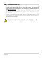
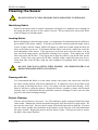
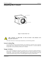
prosilica
USER MANUAL
June 24, 2008
GE1050
GE1050C
Prosilica Inc.
www.prosilica.com
tel: 604.875.8855
fax: 604.875.8856
© 2008 Prosilica Inc. All rights reserved.
GE1050 User Manual
70-0041A-A
Table of Contents
Table of Contents............................................................................................................................ ii
Introduction .................................................................................................................................1
Precautions ..................................................................................................................................1
Warranty ......................................................................................................................................1
Specifications ..............................................................................................................................2
Supported Features ......................................................................................................................3
Mechanical ..................................................................................................................................4
Connections .................................................................................................................................5
Cleaning the Sensor...................................................................................................................10
Adjusting the C-mount ..............................................................................................................11
Camera Installation....................................................................................................................12
System Optimization .................................................................................................................17
Trouble Shooting.......................................................................................................................19
Addendum......................................................................................................................................20
GE IO Schematic.......................................................................................................................21
Hirose 12-pin Trigger Schematic ..............................................................................................22
Mini-SMB Trigger Schematic...................................................................................................23
Trigger Timing Diagram ...........................................................................................................24
Notes on Triggering...................................................................................................................25
Prosilica Inc.
ii
GE1050 User Manual
70-0041A-A
Introduction
The GE1050 series of cameras are sensitive, 60 frames per second, 1 megapixel, Gigabit
Ethernet cameras based on the Kodak KAI-01050 CCD sensor.
Precautions
READ INSTALLATION GUIDE CAREFULLY.
This document contains specific information which is necessary for the correct operation and
treatment of this product.
DO NOT OPEN THE CAMERA. WARRANTY IS VOID IF CAMERA IS OPENED.
This camera contains sensitive components which can be damaged if handled incorrectly.
KEEP SHIPPING MATERIAL.
Poor packaging of this product can cause damage during shipping.
VERIFY ALL EXTERNAL CONNECTIONS.
Verify all external connections in terms of voltage levels, power requirements, voltage polarity,
and signal integrity prior to powering this device.
CLEANING.
This product can be damaged by some volatile cleaning agents. Avoid cleaning the image sensor
unless absolutely necessary. Please see instructions on sensor cleaning in this document.
DO NOT EXCEED ENVIRONMENTAL SPECIFICATIONS.
See environmental specifications limits in the Specifications section of this document.
Warranty
Prosilica provides a 2 year warranty which covers the replacement and repair of all Prosilica
parts which are found to be defective in the normal use of this product. Prosilica will not
warranty parts which have been damaged through the obvious misuse of this product.
Prosilica Inc.
1
GE1050 User Manual
70-0041A-A
Specifications
Sensor Type
Kodak KAI-01050
Sensor Shutter Type
Progressive Interline
Image Resolution
1024 x 1024 pixels
Pixel Size
5.5µm x 5.5µm
Optical Format
1/2 inch
Lens Mount
Color Sensor Filter Pattern
C-mount with adjustable back focus
†
Bayer
Full Resolution Frame Rate
59.4 fps
Frame Rate (512 x 512 ROI)
103 fps
I/O
1 isolated TTL compatible input, 3 isolated TTL
compatible outputs
Power Requirements
Less than 5.0W††
Digitization
12 Bits
Trigger latency*
5µs
Trigger Jitter*
±10ns
Tpd*
90ns
Operating Temperature
0 to 50 Celsius***
Operating Humidity
20 to 80% non-condensing
Size
39mm (height) x 51mm (width) x 80mm (length)
Weight
178g
Hardware Interface Standard
IEEE 802.3 1000BASE-T, 100BASE-TX
Software Interface Standard
GigE Vision Standard 1.0
Regulatory
Conforms to CE, FCC
†
Applies to GE1050C only.
††
Power consumption will increase with reduced ROI imaging, vertical binning, and color formats.
†††
Nominal operating voltage is 12V. Cameras have been tested at 12V.
*
See Notes on Triggering in the Addendum.
***DUE TO THE SMALL PACKAGING AND HIGH SPEED OF THE GE CAMERAS, SPECIAL
CARE IS REQUIRED TO MAINTAIN A REASONABLE OPERATING TEMPERATURE. IF THE
CAMERA IS TO BE OPERATED IN A WARM ENVIRONMENT, IT IS SUGGESTED THAT THE
CAMERA BE MOUNTED ON A HEAT SINK SUCH AS A METAL BRACKET AND THAT
THERE IS SUFFICIENT AIR FLOW.
Prosilica Inc.
2
GE1050 User Manual
70-0041A-A
Supported Features
Imaging Modes
free-running, external trigger, fixed rate, software trigger
Fixed Rate Control
0.001 fps to maximum frame rate
External Trigger Delay
0 to 60 seconds in 1 microsecond increments
External Trigger Event
rising edge, falling edge, any edge, level high, level low
Exposure Time
10 microseconds to 60 seconds in 1 microsecond increments
Gain
0 to 28dB
Region of Interest (ROI) independent x and y control with 1 pixel resolution***
Horizontal Binning
1 to 8 pixels
Vertical Binning
1 to full resolution of sensor***
Pixel Formats
Mono8, Mono16*, Bayer8, Bayer16, RGB24,
YUV411, YUV422, YUV444,
BGR24, RGBA24, BGRA24
Sync Out Modes
trigger ready, trigger input, exposing, readout, imaging,
strobe, GPO
*On monochrome versions only.
***VERTICAL BINNING AND VERTICAL ROI CAN SIGNIFICANTLY INCREASE THE POWER
CONSUMPTION OF THE CAMERA AND SHOULD ONLY BE USED INTERMITTENTLY AND
WITH CAREFUL ATTENTION TO THE OPERATING TEMPERATURE OF THE CAMERA.
Prosilica Inc.
3
GE1050 User Manual
70-0041A-A
Mechanical
M3
4 MM DEEP
4 PLCS TYP
40
35
M3
3 MM DEEP
6 PLCS TYP
13.7*
26
26
80.2*
57
64
All dimensions are in mm.
*Add 0.3mm for color cameras due
to addition of IR blocking filter.
51.6
39.4
Figure 1. GE SERIES mechanical dimensions.
Prosilica Inc.
4
GE1050 User Manual
70-0041A-A
Connections
5
6
1
2
7
3
4
Figure 2. GE SERIES connection diagram.
Prosilica Inc.
5
GE1050 User Manual
70-0041A-A
Item 1: GIGABIT ETHERNET PORT
This port conforms to the IEEE 802.3 1000BASE-T standard for Gigabit Ethernet over copper.
It is recommended that CAT5E or CAT6 compatible cabling and connectors be used for best
performance. Cable lengths up to 100m are supported.
Item 2: General Purpose I/O PORT
PIN
FUNCTION
1
Trigger Input
2
Sync Out 2
1
3
Sync Out 3
10
11 2
4
RS-232 RXD
5
RS-232 TXD
3
6
DNC
7
DNC
8
DNC
9
DNC
10
Isolated Ground
11
Isolated Ground
Figure 3. General Purpose I/O Pin out. Camera rear view. 12
Isolated Ground
9
8
12
7
6
5
4
The General Purpose I/O port uses a Hirose HR10A-10R-12SB connector on the camera side.
The mating cable connector is Hirose HR10A-10P-12P. This connector can be purchased from
Prosilica or from http://www.digikey.com.
See Addendum for more detail.
DO NOT EXCEED 5.5V ON SIGNAL INPUTS.
All inputs and outputs are galvanically isolated from the internal camera circuitry.
TRIGGER INPUT
This input signal allows the camera to be synchronized to some external event. The camera can
be programmed to trigger on the rising or falling edge of this signal. The camera can also be
programmed to capture an image at some programmable delay time after the trigger event.
Prosilica Inc.
6
GE1050 User Manual
70-0041A-A
Sync Out 2 and Sync Out 3
These signals only function as outputs and can be configured as follows:
Exposing
Corresponds to when camera is
integrating light.
Trigger Ready
Indicates when the camera will accept a
trigger signal.
Trigger Input
A relay of the trigger input signal used
to “daisy chain” the trigger signal for
multiple cameras.
Readout
Valid when camera is reading out data.
Strobe
Programmable pulse based on one of the
above events.
Imaging
Valid when camera is exposing or
reading out.
GPO
User programmable binary output.
Any of the above signals can be set for active high or active low.
RS-232 RXD and RS-232 TXD
These signals are RS-232 compatible. These signals allow communication from the host system
via the Ethernet port to a peripheral device connected to the camera.
ISOLATED GROUND
These signals are internally connected to isolated ground. At least one of these signals must be
connected to the users external circuit ground. However, it is good practice to provide a
dedicated ground return for each signal used. For example, a good cable design would connect
the required signal on one conductor of a twisted pair and the isolated ground on the second
conductor of the same twisted pair.
DNC
These signals are reserved for future use and should be left disconnected.
Item 3: Mini-SMB Trigger Input
The Mini-SMB port on the camera uses an Amphenol 903-406J-51R connector. A suitable
mating cable connector is Amp 413985-3 which can be used with RG174 coaxial cable. Contact
Prosilica to purchase cabling.
The Mini-SMB Trigger Input is internally connected to the Trigger Input (Pin 1) of the General
Purpose I/O Port (Item 2 above). Therefore see this section for more detail.
Prosilica Inc.
7
GE1050 User Manual
70-0041A-A
Item 4: Mini-SMB Sync Out 1
This Mini-SMB port on the camera uses an Amphenol 903-406J-51R connector. A suitable
mating cable connector is Amp 413985-3 which can be used with RG174 coaxial cable. Contact
Prosilica to purchase cabling.
This connector is particularly useful for triggering multiple cameras in a “daisy chain” fashion.
The Sync Out 1 signal can be configured as follows:
Exposing
Corresponds to when camera is
integrating light.
Trigger Ready
Indicates when the camera will accept a
trigger signal.
Trigger Input
A relay of the trigger input signal used
to “daisy chain” the trigger signal for
multiple cameras.
Readout
Valid when camera is reading out data.
Strobe
Programmable pulse based on one of the
above events.
Imaging
Valid when camera is exposing or
reading out.
GPO
User programmable binary output.
Any of the above signals can be set for active high or active low.
Item 5: Status LED 1
LED COLOR
STATUS
Solid Green
Ethernet link established.
Flashing Green
Ethernet activity.
Item 6: Status LED 2
LED COLOR
STATUS
Solid Green
Normal operation.
Solid Orange
Firmware missing.
Flashing Orange
Camera fault.
Prosilica Inc.
8
GE1050 User Manual
70-0041A-A
Item 7: AUXILIARY POWER PORT
This port is required to provide power to the camera.
This port provides threaded captivation of the power cable if required. The captivated cable
mating connector is the Switchcraft 760K. This connector can be purchased from Prosilica or
from http://www.digikey.com.
This port can accept from 5V to 17V DC with the inner conductor being positive power and the
external conductor being ground. However the suggested nominal voltage is 12V and cameras
are tested at 12V.
Cameras will normally include a power supply. However compatible power supplies can also be
ordered separately from Prosilica (Prosilica P/N 02-8000A for North America or Prosilica P/N
02-8001A for a Universal supply).
THE CAMERA POWER SUPPLY OPERATES MOST EFFICIENTLY AT 12V.
Prosilica Inc.
9
GE1050 User Manual
70-0041A-A
Cleaning the Sensor
DO NOT CONTACT CLEAN SENSOR UNLESS ABSOLUTELY NECESSARY.
Identifying Debris
Debris on the image sensor or optical components will appear as a darkened area or smudge on
the image that does not move as the camera is moved. Do not confuse this with a pixel defect
which will appear as a distinct point.
Locating Debris
Before attempting to clean the image sensor, it is important to first determine that the problem is
due to debris on the sensor window. To do this you should be viewing a uniform image, such as
a piece of paper, with the camera. Debris will appear as a dark spot or dark region that does not
move as the camera is moved. To determine that the debris is not on the camera lens, rotate the
lens independent of the camera. If the spot moves as the lens moves, then the object is on the
lens -not on the image sensor- and therefore cleaning is not required. If the camera has an IR
filter, then rotate the IR filter. If the object moves then the particle is on the IR filter not the
sensor. If this is the case remove the IR filter carefully using a small flat head screw driver.
Clean both sides of the IR filter using the same techniques as explained below for the sensor
window.
DO NOT TOUCH ANY OPTICS WITH FINGERS. OIL FROM FINGERS CAN
DAMAGE FRAGILE OPTICAL COATINGS.
Cleaning with Air
If it is determined that debris is on the sensor window, then remove the camera lens, and blow
the sensor window directly with clean compressed air. If canned air is used, do not shake or tilt
the can prior to blowing the sensor. View a live image with the camera after blowing. If the
debris is still there, repeat this process. Repeat the process a number of times with increased
intensity until it is determined that the particulate cannot be dislodged. If this is the case then
proceed to the contact cleaning technique.
Contact Cleaning
Only use this method as a last resort. Use 99% laboratory quality isopropyl alcohol and clean
cotton swabs. Dampen the swab in the alcohol and gently wipe the sensor in a single stroke. Do
not reuse the same swab. Do not wipe the sensor if the sensor and swab are both dry. You must
wipe the sensor quickly after immersion in the alcohol, or glue from the swab will contaminate
the sensor window. Repeat this process until the debris is gone. If this process fails to remove
the debris, then contact Prosilica.
Prosilica Inc.
10
GE1050 User Manual
70-0041A-A
Adjusting the C-mount
LOCKING RING
C MOUNT RING
Figure 4. Camera Front View.
THE C-MOUNT IS ADJUSTED AT THE FACTORY AND SHOULD NOT
REQUIRE ADJUSTING.
If for some reason, the C-mount requires adjustment, use the following method.
Loosen Locking Ring
Use an adjustable wrench to loosen locking ring. Be careful not to scratch the camera. When the
locking ring is loose, unthread the ring a few turns from the camera face. A wrench suitable for
this procedure can be provided by Prosilica (P/N 11-0048A).
Image to Infinity
Use a c-mount compatible lens that allows an infinity focus. Set the lens to infinity and image a
distant object. The distance required will depend on the lens used but typically 30 to 50 feet
should suffice. Make sure the lens is firmly threaded onto the c-mount ring. Rotate the lens and
c-mount ring until the image is focused. Carefully tighten locking ring. Recheck focus.
Prosilica Inc.
11
GE1050 User Manual
70-0041A-A
Camera Installation
Computer Interface
The Prosilica GE Series cameras will work with any Gigabit Ethernet network card; however
Prosilica strongly recommends using Gigabit Ethernet components that support Jumbo Frames.
A Jumbo Frame is loosely defined as a frame size greater than 1500 bytes however typical
Jumbo Frames are around 9000 bytes. Frame size is the number of bytes per packet and the
larger the frame size, the less the computer CPU will be loaded due to the processing of
incoming packets.
There are many Gigabit Ethernet cards available which will support Jumbo Frames. The
following examples have been verified to work well with the Prosilica cameras:
•
Intel PRO/1000
•
D-Link DGE-550T
•
SMC EZ Card 1000
Gigabit Ethernet cards supporting this feature can also be purchased with the camera (Prosilica
P/N 02-3002A).
Prosilica Inc.
12
GE1050 User Manual
70-0041A-A
Gigabit Ethernet Setup for Windows
o Install network card in computer.
o Boot the PC and cancel the “Found new Hardware Wizard” window that may appear when
Windows detects the new card.
o Install the driver that came with the network card.
o Once the driver is installed, open the Network Connections Dialog as follows: From the
Windows desktop select start, then select Control Panel, then double click on the Network
Connections icon. Double click the relevant network card listed or right-click the relevant
network card and select Properties. This will open the properties window for your network
card. See Figure 5.
Figure 5. Network card main properties window.
Prosilica Inc.
13
GE1050 User Manual
70-0041A-A
o Select the Internet Protocol (TCP/IP) check box and then select Properties. See Figure 6.
Network card TCP/IP address.. Select the Use the following IP address and enter an IP
address of 169. 254. x. y, where x and y can be any number. Press the TAB key after entering
the IP address and the subnet mask will automatically be entered. The subnet mask is 255.
255. 0. 0. Click OK to save changes. Note that if Windows reports a conflict with the above
IP address, simply repeat the above steps and change the last digit of the IP address to a
different value.
Figure 6. Network card TCP/IP address.
Prosilica Inc.
14
GE1050 User Manual
70-0041A-A
Figure 7. Turn off Firewall.
o Return to the Gige Local Properties window as in Figure 5. Select the Advanced tab as in
Figure 7 and disable the Firewall for this device. Click OK to save changes.
Gigabit Ethernet Cabling
All Gigabit Ethernet cabling and connectors should be CAT5E or CAT6 compatible. Cable
lengths must not exceed 100 meters.
Power Connection
The camera requires a 12V DC power supply that can source a minimum of 500 mA of current.
See the Connections section of this document for more information.
Other Cabling
The camera can be triggered either through the 12 pin general purpose connector or the miniSMB input. The compatible cable connectors are specified in the Connections section of this
document or contact Prosilica to purchase compatible cabling. Prosilica provides SMB-to-SMB
or SMB-to-BNC cabling of varying lengths.
Prosilica Inc.
15
GE1050 User Manual
70-0041A-A
Installing GigE Viewer for Testing
o The latest Viewer software can be downloaded from http://www.prosilica.com/support.htm.
o Run the GigE Viewer Installer.exe. This will install the Prosilica Digital Camera drivers as
well as the Prosilica GigE Viewer application program.
o Plug in the Prosilica camera via the Gigabit Ethernet port. Plug in the power connection.
Verify that the Status LED 1 is a solid green. Run the Prosilica GigE Viewer Application. It
will take a few seconds for the camera to be recognized. If the camera does not appear in the
Viewer list after approximately 10 seconds then try disconnecting and reconnecting the
power. If it still does not appear restart the viewer. If it still does not appear, see the Trouble
Shooting section of this document.
o See Figure 8. Select the wrench icon to change camera settings. Change the PacketSize to a
value of 1500. Select the eye icon to image. The camera should now be imaging. If the
camera is not imaging, see the Trouble Shooting section of this document. Note that the
PacketSize can be set to 8228 if the network card has been optimized to support jumbo
frames.
o See the System Optimization Section to maximize the performance of your system.
Figure 8. GigE Viewer application window.
Prosilica Inc.
16
GE1050 User Manual
70-0041A-A
System Optimization
o Open the Network Connections Dialog as follows: From the Windows desktop select start,
then select Control Panel, then double click on the Network Connections icon. Double click
the relevant network card listed or right-click the relevant network card and select Properties.
This will open the properties window for your network card. See Figure 9.
Figure 9. Network card main properties window.
o From the Properties window select Configure then select the Advanced tab. See Figure 10.
Prosilica Inc.
17
GE1050 User Manual
70-0041A-A
Figure 10. Network card advanced settings.
o Set Maximum Frame Size or Jumbo Frames to the maximum possible value. A typical
value is 9000. If the list contains a property called Receive Descriptors, then change this
value to its maximum value. Select OK to save properties.
o From the main properties dialog as in Figure 9, make sure that only the Internet Protocol
(TCP/IP) check box is selected then click OK. The card is now optimized for use with the
Prosilica camera.
o Open the viewer and set the PacketSize to 8228.
Prosilica Inc.
18
GE1050 User Manual
70-0041A-A
Trouble Shooting
Check the Basics
o Is power available? Check the status LED 1. If the LED is off, the camera is not getting
power. Verify the connections and cabling.
o Is the LED orange? This occurs if the firmware is corrupt because a firmware update was
interrupted. If the LED is orange, run the firmware updater again, carefully following the
instructions. If the problem persists, contact Prosilica.
o Is the LED flashing orange? This indicates a fault with the camera. If this problem persists,
please contact Prosilica.
Test the Camera with the Prosilica Viewer
Download and install the Prosilica Viewer (from http://www.prosilica.com/support.htm).
o Can the Viewer find the camera? Is the camera listed in the main application window or is
the list empty? If the camera is not listed, proceed to Driver Issues.
o Is the image black? If so, check the optics. Check that lens iris is fully open. Check
exposure time - in room lighting, an exposure time of 30ms should be adequate to see an
image. If image is still black, contact Prosilica.
o Is the image white?
•
If the camera is in external trigger mode, a snapshot will not complete until a
hardware trigger is received.
•
Image data may fail to arrive at the computer if there is a problem with the driver. If
you suspect a driver problem, proceed to Driver Issues.
o Is the image white, but the camera is not waiting for an external trigger? Do you have a lens?
Check your exposure time, offset, and gain controls.
o Does the image occasionally freeze? Test the camera with an alternate Ethernet cable and
card. If the problem persists, contact Prosilica.
•
An intermittent connection will result in the loss of image data, but you likely will not
notice a problem when using the camera controls.
Driver Issues
TBD.
Camera will not trigger
Check cabling and connections. Verify that external trigger circuit is providing a compatible
trigger signal. Use the Prosilica Viewer program in trigger mode to eliminate possible software
issues.
Prosilica Inc.
19
GE1050 User Manual
70-0041A-A
Addendum
Prosilica Inc.
20
GE1050 User Manual
70-0041A-A
GE IO Schematic
HIROSE HR10A-10R-12SB
1
9
10
8
2
7
3
6
12
11
CAMERA INTERNAL CIRCUIT
1
2
3
4
5
6
7
8
9
10
11
12
4
5
TRIGGER INPUT
SY NC OUT 2
SY NC OUT 3
RS-232 RXD
RS-232 TXD
18
16
14
12
SY NC OUT 3
SY NC OUT 2
SY NC OUT 1
TEXAS INSTRUMENTS
SN74ACT244PWR
2
1Y 1
1A1 4
1Y 2
1A2 6
1Y 3
1A3 8
1Y 4
1A4
9
7
5
3
AS SEEN FROM
CAMERA REAR
VIEW
2Y 1
2Y 2
2Y 3
2Y 4
2A1
2A2
2A3
2A4
1OE
2OE
VCC
GND
11
13
15
17
ISO+5V
NVE
IL716-3
16
15
14
13
12
11
10
9
ISO+5V
1
19
20
10
ISO_+5V
MINI-SMB
ISO+5V
VDD2
GND2
OUT1
OUT2
IN3
IN4
NC
GND2
VDD1
GND1
IN1
IN2
OUT3
OUT4
NC
GND1
1
2
3
4
5
6
7
8
NVE
IL716-3
TRIGGER INPUT
IN
VDD-3.3
TRIGGER INPUT
LOGIC SY NC OUT 1
LOGIC SY NC OUT 2
LOGIC TRIGGER INPUT
VDD-3.3
ISO+5V
MAXIM
MAX3221CPWR
1
0.1u
2
0.1u
3
4
0.1u
5
MINI-SMB
OUT
SY NC OUT 1
6
0.1u
7
8
EN
C1+
FORCEOFF
VCC
V+
GND
C1-
DOUT
C2+
FORCEON
C2VRIN
DIN
INVALID
ROUT
16
15
14
13
12
11
10
9
16
15
14
13
RS232-TXD
VDD2
GND2
OUT1
OUT2
IN3
IN4
NC
GND2
VDD1
GND1
IN1
IN2
OUT3
OUT4
NC
GND1
1
2
3
4
5
6
7
8
LOGIC SY NC OUT 3
LOGIC TXD
LOGIC RXD
12
11
ISO TXD
10
9
ISO RXD
ISO+5V
RS232-RXD
ISOLATED 5V POWER
ISOLATED GROUND
GALVANIC
ISOLATION
BOUNDARY
Prosilica Inc.
21
GE1050 User Manual
70-0041A-A
Hirose 12-pin Trigger Schematic
USERS TRIGGER CIRCUIT
CABLE SIDE
USER TRIGGER (5V TTL DRIVER)
TRIGGER INPUT
SY NC OUT 2
SY NC OUT 3
SY NC OUT 2 (5V TTL RECEIVER)
SY NC OUT 3 (5V TTL RECEIVER)
1
2
3
4
5
6
7
8
9
10
11
12
1
9
10
2
8
3
7
4
11
12
6
5
HIROSE HR10A-10P-12P
ONE GROUND
RETURN IS
SUFFICIENT.
The trigger circuit is connected to a Texas Instruments SN74ACT244PWR buffer/driver inside the camera. The required trigger input current
is less than 10uA and the maximum sync output current is 24mA. See the Texas Instruments SN74ACT244PWR for more detailed
information.
Prosilica Inc.
22
GE1050 User Manual
70-0041A-A
Mini-SMB Trigger Schematic
USERS TRIGGER CIRCUIT
RG-174 COAX CABLE
MINI-SMB
TRIGGER INPUT
USER TRIGGER (5V TTL DRIVER)
IN
RG-174 COAX CABLE
MINI-SMB
SY NC OUT 1 (5V TTL RECEIVER)
SY NC OUT 1
OUT
The trigger circuit is connected to a Texas Instruments SN74ACT244PWR buffer/driver inside the camera. The required trigger input current
is less than 10uA and the maximum sync output current is 24mA. See the Texas Instruments SN74ACT244PWR for more detailed
information.
Note that the trigger input signal is not terminated to match the cable impedance.
Prosilica Inc.
23
GE1050 User Manual
70-0041A-A
Trigger Timing Diagram
Readout Time
Trigger
Latency
Tpd
User Trigger
Expose Start
Delay
Registered
Exposure Time
Logic Trigger
Exposure
Readout
N
Trigger
Jitter
N+1
N
N+1
Interline Time
Trigger Ready
Imaging
Idle
Prosilica Inc.
24
GE1050 User Manual
70-0041A-A
Notes on Triggering
Definitions
o User Trigger is the trigger signal applied by the user.
o Logic Trigger is the trigger signal seen by the camera internal logic.
o Tpd is the propagation delay between the User Trigger and the Logic Trigger.
o Exposure is high when the camera image sensor is integrating light.
o Readout is high when the camera image sensor is reading out data.
o Trigger Latency is the time delay between the User Trigger and the start of Exposure.
o Trigger Jitter is the error in the Trigger Latency time.
o Trigger Ready indicates to the user that the camera will accept the next trigger.
o Registered Exposure Time is the Exposure Time value currently stored in the camera
memory.
o Expose Start Delay is the delay time from the start of Exposure to valid Trigger Ready. It is
the Registered Exposure Time subtracted from the Readout time and indicates when the next
Exposure cycle can begin such that the Exposure will end after the current Readout.
o Interline Time is the time between sensor row readout cycles.
o Imaging is high when the camera image sensor is either exposing and/or reading out data.
o Idle is high if the camera image sensor is not exposing and/or reading out data.
Rules
o The User Trigger pulse width should be at least three times the width of the Trigger Latency
as indicated in the Specifications section of this document.
o The end of Exposure will always trigger the next Readout.
o The end of Exposure must always end after the current Readout.
o The start of Exposure must always correspond with the Interline Time if Readout is true.
o Expose Start Delay equals the Readout time minus the Registered Exposure Time.
Triggering during the Idle State
o For applications requiring the shortest possible Trigger Latency and the smallest possible
Trigger Jitter the User Trigger signal should be applied when Imaging is false and Idle is
true.
o In this case, Trigger Latency and Trigger Jitter are as indicated in the Specifications section.
Prosilica Inc.
25
GE1050 User Manual
70-0041A-A
Triggering during the Readout State
o For applications requiring the fastest triggering cycle time whereby the camera image sensor
is exposing and reading out simultaneously, then the User Trigger signal should be applied as
soon as a valid Trigger Ready is detected.
o In this case, Trigger Latency and Trigger Jitter can be up to 1 line time since Exposure must
always begin on an Interline boundary.
Prosilica Inc.
26