1
Version 1.0
Produced in Jan. 2002
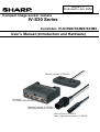
Compact image sensor camera
IV-S30 Series
Controller: IV-S31MX/S32MX/S33MX
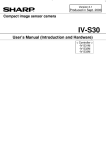
User’s Manual (Introduction and Hardware)
Remote keypad: IV-S30RK1
Controller:
IV-S31MX/32MXS33MX
Standard camera: IV-S30C1
High-speed camera: IV-S30C3
Micro camera: IV-S30C2
Micro, high-speed camera: IV-S30C4
Thank you for purchasing the SHARP IV-S30 compact image sensor camera (IV-S31MX/S32MX/S33MX
controller).
Read this introductory user's manual carefully to thoroughly familiarize yourself with the functions and proper
procedures for operation.
Store this user's manual in a safe place. We are confident that the manual will be helpful whenever you
encounter a problem.
In addition to this manual, there are other IV-S30 (IV-S31MX/S32MX/S33MX) manuals as follows. Read them
in conjunction with this manual.
IV-S30 (IV-S31MX/S32MX/S33MX)
User’s Manual (Introduction and Hardware: This manual)
User’s Manual (Function and Operation)
Instruction Manual
Manual type
Major subjects
- Outline of the IV-S30 (features and
IV-S30
functions)
(IV-S31MX/S32MX/S33MX) - Description of the hardware
User's Manual
- Startup method
(Introduction and Hardware) - General performance specifications.
- Example of operation and instruction
- Detailed explanations of all the
measurement functions.
- How to make menu selections for
IV-S30
(IV-S31MX/S32MX/S33MX) each measurement
User's manual
- Details of inputting and outputting
(Function and Operation)
data and communications with other
devices.
- Troubleshooting
How to use
- Become acquainted with the IV-S30
- Learn how to install the IV-S30 and
wire it up
- When mastering the outline of
operation
- Learn how to specify measurement
/inspection conditions, good or NG
judgment conditions, etc.
- Lear how to connect a programmable
controller or personal computer.
- Learn what to do if a problem occurs.
Notes
- This manual was written with the utmost care. However, if you have any questions or
inquiries concerning the product, please feel free to contact our dealers or service agents.
- Copying all or part of this booklet is prohibited.
- The contents of this manual may be revised or modified for improvement without prior
notice.
Safety Precautions
Read this user's manual and the attached documents carefully before installing, operating, or performing any
maintenance, in order to keep the machine working correctly. Make sure you understand all of the equipment
details, safety information, and cautions before using this machine. In this user's manual, the safety
precautions are divided into "Dangers" and "Cautions" as follows.
Danger
: Improper handling is likely to lead to death or serious injury.
Caution
: Improper handling may lead to injury or damage to equipment.
Even when only a
Caution is given, serious results may occur depending on the
circumstances. In all cases, important points are described. Be sure to follow the
advice given.
The following symbols are used to prohibit or explain required action.
: This means do not do what is described. For example, prohibited disassembly is shown as
: This means an action you must take. For example, a ground connection that must be made is
shown as
.
(1) Installation
Caution
- Use only in the environments specified in the rinstruction manual, or user's manual.
Electric shock, fire or malfunction may result if used in high temperature, high humidity,
dusty or corrosive environments, or if excessive vibration or impact occurs.
- Install the equipment only as described in the manual.
An improper installation may cause the equipment to fail, breakdown, or malfunction.
- Never leave wire cuttings or any other foreign matter lying about.
A fire, breakdown or malfunction may result from inappropriate objects left near the equipment.
(2) Wiring
Caution
- Do not connect any camera not specified by SHARP to the IV-S31MX/S32MX/S33MX controller.
Connecting any other camera to the controller may damage the controller or the camera.
- Connect only to the specified power source.
Connection to the wrong power source may cause a fire.
- Wiring should be performed by a qualified electrician.
Improper wiring may lead to a fire, machine failure or electric shock.
(3) Use
Danger
- Don't touch the terminals while the power is turned ON or you may receive an electric shock.
- Assemble an external emergency stop circuit and interlock circuit (external to the IV-S30
compact image sensor camera). Otherwise a breakdown or damage to other equipment may
occur due to a problem with the IV-S30.
Caution
- Take special care to follow all safety guidelines if you are changing the parameters for the
operating conditions or performing an "enforced output," "run," or "stop" during operation.
Misoperation may damage the machine or cause an accident.
- Turn ON the power supplies in the specified sequence. Turning ON the supplies in the wrong
order may lead to a machine breakdown or cause an accident.
.
(4) Maintenance
Warning
- The IV-S32MX/S33MX controller contains a lithium battery. Do not expose the IV-S32MX
/S33MX directly to flames as the battery may explode and seriously injure people nearby.
Prohibit
- Don't disassemble or modify the camera.
Fires, breakdowns or malfunctions may occur, if the camera is disassembled.
Caution
- Turn OFF the power source before connecting or disconnecting the IV-S30.
If you don't, electric shocks, malfunctions or breakdowns may occur.
Chapter 1: Outline
Chapter 2: Precautions for Use
Chapter 3: System Configuration
Chapter 4: Part Names and Functions
Chapter 5: Connection and Installation Methods
Chapter 6: Setting and Operating Outlines
Chapter 7: Setting Examples Using the Setting Wizard
Chapter 8: Setting Examples Using the Menu Tree
Chapter 9: Specifications
Glossary
Appendix
Alphabetical Index
Table of contents
Chapter 1: Outline .......................................................................................... 1-1 to 1-13
1-1 Features ....................................................................................................................................... 1-1
1-2 Controller ..................................................................................................................................... 1-5
[1] Software version of the controllers............................................................................................. 1-6
[2] Differences between types of controllers ................................................................................... 1-6
1-3 Measurement program ................................................................................................................ 1-7
[1] Positional deviation measurement ............................................................................................. 1-7
[2] Degree of match inspection ....................................................................................................... 1-8
[3] Lead inspection .......................................................................................................................... 1-8
[4] BGA/CSP inspection (IV-S32MX/S33MX) ................................................................................. 1-9
[5] Area measurement by binary conversion ................................................................................... 1-9
[6] Object counting by binary conversion ...................................................................................... 1-10
[7] Object identification (labeling) by binary conversion ................................................................ 1-10
[8] Point measurements ................................................................................................................. 1-11
[9] Multiple position measurement (IV-S33MX)............................................................................. 1-12
[10] Multiple degree of match inspection (IV-S33MX) ................................................................... 1-13
[11] Distance and angle measurement ......................................................................................... 1-13
Chapter 2: Precautions for Use ................................................................................ 2-1
(1) Installation ............................................................................................................................
(2) Mounting ...............................................................................................................................
(3) Power source .......................................................................................................................
(4) Measurement settings ..........................................................................................................
(5) Data saving ..........................................................................................................................
(6) Storing the devices ...............................................................................................................
(7) Maintenance .........................................................................................................................
2-1
2-1
2-1
2-1
2-1
2-1
2-1
Chapter 3: System Configuration ................................................................... 3-1 to 3-7
3-1 Basic system configuration ..........................................................................................................
[1] When the IV-S31MX/S32MX is used as the controller ...............................................................
[2] When the IV-S33MX controller is used ......................................................................................
3-2 System configuration examples ..................................................................................................
[1] System configuration example for measurement triggered by an external trigger,
such as a photo sensor .............................................................................................................
(1) When IV-S30 is used in a stand-alone mode .......................................................................
(2) When a programmable controller is connected ....................................................................
(3) When a personal computer is connected .............................................................................
[2] System configuration example for measurement triggered by the internal CCD sensor trigger
(1) When IV-S30 is used in a stand-alone mode .......................................................................
(2) When a programmable controller is connected ....................................................................
(3) When a personal computer is connected .............................................................................
[3] System configuration example for measurement triggered by a command from a personal
computer ....................................................................................................................................
3-1
3-1
3-2
3-4
3-4
3-4
3-4
3-5
3-5
3-5
3-6
3-6
3-7
Chapter 4: Part Names and Functions ........................................................... 4-1 to 4-7
4-1 Controller (IV-S31MX/S32MX/S33MX) ........................................................................................ 4-1
4-2 Camera ........................................................................................................................................ 4-2
[1] Camera ......................................................................................................................................
(1) Standard camera (IV-S30C1) ...............................................................................................
(2) Micro camera (IV-S30C2) .....................................................................................................
(3) High-speed camera (IV-S30C3) ...........................................................................................
(4) Micro, high-speed camera (IV-S30C4) .................................................................................
[2] Connects to commercially available EIA cameras .....................................................................
(1) Camera converter IV-S30EA1 ..............................................................................................
(2) Cable to connect the camera converter to the controller ......................................................
(3) Connection example using an EAI camera ..........................................................................
[3] Camera lens (IV-S20L16) ..........................................................................................................
[4] Camera cable (IV-S30KC3/KC5/KC7) .......................................................................................
4-3 Remote keypad (IV-S30RK1) ......................................................................................................
4-2
4-2
4-2
4-3
4-3
4-4
4-4
4-5
4-5
4-6
4-6
4-7
Chapter 5: Connection and Installation Methods ....................................... 5-1 to 5-35
5-1 Installation conditions ................................................................................................................. 5-1
[1] Lighting equipment ..................................................................................................................... 5-1
(1) Backlighting .......................................................................................................................... 5-1
(2) Reflective lighting ................................................................................................................. 5-1
[2] Illuminance and shutter speed ................................................................................................... 5-3
[3] Optimum lens and resolution ..................................................................................................... 5-4
5-2 Installing, connecting and wiring the IV-S31MX/S32MX/S33MX controller ................................ 5-11
[1] Connecting equipment to the controller .................................................................................... 5-11
[2] Installation ................................................................................................................................ 5-13
[3] Connecting a power supply ...................................................................................................... 5-15
[4] Connecting to the input/output terminals (parallel I/F) ............................................................. 5-16
(1) Input terminals (INPUT) X0 to X7 ....................................................................................... 5-17
(2) Output terminals (OUTPUT) Y0 to Y7 and READY ........................................................... 5-18
(3) I/O port ............................................................................................................................... 5-18
(4) Wiring to the controller (IV-S31MX/S32MX/S33MX) .......................................................... 5-18
[5] Connection for communications with personal computer (general purpose serial I/F) ............ 5-19
(1) When communicating through the RS-232C port ............................................................... 5-19
(2) When communicating through the RS-422 ........................................................................ 5-20
[6] Connecting a programmable controller using the computer link function ................................ 5-21
5-3 Installing and connecting the IV-S30C1/C2/C3/C4 camera ....................................................... 5-22
[1] Installing and connecting the IV-S30C1/C3 standard and high-speed cameras ...................... 5-22
(1) Connections ....................................................................................................................... 5-22
(2) Installing the camera body ................................................................................................. 5-23
[2] Installing and connecting the IV-S30C2/C4 micro camera or micro, high-speed camera ........ 5-25
(1) Connections ....................................................................................................................... 5-25
(2) Installation of the camera head .......................................................................................... 5-27
(3) Installation of the camera body .......................................................................................... 5-28
5-4 Installing, connecting, and wiring the IV-S30EA1 camera converter ......................................... 5-30
[1] Connection to the IV-S33MX controller .................................................................................... 5-30
[2] Connection to an EIA camera .................................................................................................. 5-31
(1) Cameras that can be connected ........................................................................................ 5-31
(2) Connecting between the IV-S30EA1 and an EIA camera .................................................. 5-31
[3] Installing the camera converter (IV-S30EA1) ........................................................................... 5-32
(1) Installation procedures ....................................................................................................... 5-32
(2) Installation example ............................................................................................................ 5-34
[4] Wiring of the camera converter (IV-S30EA1) ........................................................................... 5-35
Chapter 6: Setting and Operating Outlines ................................................. 6-1 to 6-15
6-1 Setting and operating procedures ................................................................................................ 6-1
6-2 Description of the operation screen ............................................................................................. 6-2
6-3 Wizard .......................................................................................................................................... 6-5
[1] How to start the standard wizard ............................................................................................... 6-5
[2] Other operations in the "Set wizard" program ............................................................................ 6-6
6-4 Operation chart ............................................................................................................................ 6-8
[1] Method for displaying the operation chart .................................................................................. 6-8
[2] How to edit an operation chart ................................................................................................... 6-9
6-5 Menu tree .................................................................................................................................... 6-11
6-6 Relationship between the set wizard program, the operation chart, and the menu tree ............ 6-13
6-7 Editing operation screen ............................................................................................................ 6-14
6-8 Option ........................................................................................................................................ 6-15
Chapter 7: Setting Examples Using the Setting Wizard ............................. 7-1 to 7-19
7-1 Position deviation measurement .................................................................................................. 7-1
7-2 Area measuremetnt by binary conversion .................................................................................. 7-11
Chapter 8: Setting Examples Using the Menu Tree .................................... 8-1 to 8-13
8-1 Position deviation measurement .................................................................................................. 8-1
8-2 Area measurement by binary conversion .................................................................................... 8-8
Chapter 9: Specifications ................................................................................ 9-1 to 9-9
9-1 Controller (IV-S31MX/S32MX/S33MX) ........................................................................................
9-2 Camera specifications .................................................................................................................
[1] Camera (IV-S30C1/C2/C3/C4) ...................................................................................................
[2] Camera converter (IV-S30EA1) .................................................................................................
[3] Camera lens (IV-S20L16) ..........................................................................................................
[4] Camera cable (IV-S30KC3/KC5/KC7) .......................................................................................
9-3 Support tools ................................................................................................................................
[1] Monochrome monitor (IV-09MT) ................................................................................................
[2] LCD monitors (IV-10MT/10MTV/10MTK) ...................................................................................
[2] LED lighting equipment (IV-60LD) .............................................................................................
9-1
9-4
9-4
9-5
9-6
9-6
9-7
9-7
9-8
9-9
Glossary ............................................................................................... Glossary-1 to 13
Appendix ............................................................................................... Appendix-1 to 2
Alphabetical Index ................................................................ Alphabetical Index-1 to 5
Outline
Chapter 1: Outline
This compact image sensor camera system, the IV-S30, dramatically reduces overall processing time,
thanks to a camera with double and quadruple speeds (using the IV-S33MX controller), SHARP’s partialimage capture function, and a high-speed gray search function. It will not only contribute to high-speed,
high-efficiency inspection and measurement processes, but it will also help you keep your prices
competitive.
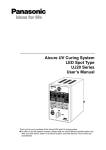
1-1 Features
Easy operation menu
(1) Setting wizard
The IV-S31MX/S32MX/S33MX wizard asks you to make selections using a questionnaire, thus
allowing anyone to set up the measurement operations and preferences, and decrease the chance of
mistaken settings.
STEP2
SELECT AN IMAGE CAPTURING
METHOD DURING OPERATION
1PARTIAL-IMG
■
2ALL IMAGE
□
3NO CAPTURED
□
STEP1
SELECT THE MEASUREMENT
START INPUT I/F
1PARALLEL+SERIAL+USB ■
2TRIG CCD START
□
STEP10
STORE THIS SETTING AS A
SAMPLE IN THE WIZARD?
1NO
□
2YES
■
・・・
RETURN END
NEXT DETAIL
ENTER A SHUTTER SPEED
(1/30∼1/10000)
1SHUTTER SPEED 1/00060
RETURN NEXT
(2) Tree menu
The tree structure menu lets you find the setting parameter you need
easily. Using the short cut function, you can move directly to a desired
menu.
OBJECT TYPE COND
+ TYPE00
TYPE RUN COND
IMAGE-ADJ
MEA-CND(CAMERA1)
MEAS0
POSI-CORRECT
+ MEAS01(MEAS-BIN-AREA)
MEAS(NEW)
+ MEA-CND(CAMERA2)
FINAL NUM.CALC
FINAL OUTPUT COND
OBJ-TYPE I/O
OBJ-TYPE SYS.
TYPE(NEW)
Operation screen editing function
You can move, remove, enlarge, and decrease the size of the information displayed on the operation
screen.
(TYPE00)
(TYPE00)
F C1 BRT
VX.XX
OK
F C1 BRT
OK
MEAS XXXXms 2001-10-14 10:38
MEASUREMENT 1
MEAS-BIN-AREA
MEAS XXXXms 2001-10-14 10:38
MEASUREMENT 1
MEAS-BIN-AREA
A00=001884
A01=
A02=
A03=
A04=
A05=
A06=
A07=
A00=001884
A01=
A02=
A03=
A04=
A05=
A06=
A07=
OK
OK
OK
X0∼7
Y0∼7
READY
X0∼7
MNU-CHG MAIN-COND CHG-MEA COND-CHG CHNG-REG SCREEN-CHG CHG-TYPE
Y0∼7
READY
MNU-CHG MAIN-COND CHG-MEA COND-CHG CHNG-REG SCREEN-CHG CHG-TYPE
1-1
1
Outline
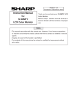
It is now possible to inspect every item in a production run, thanks to highspeed processing
1
High-speed camera offers double and quadruple speeds. SHARP’s unique partial-image capture function
and high-speed gray search function provide higher overall speed. This system can inspect
approximately 5,000 * pieces per minute (using the IV-S33MX controller). Such high speed makes it
possible to inspect all the chips or parts in a production lot.
Conventional model (IV-S20)
Approx. 28 ms
Total
processing
time: Approx.
40 ms
Approx. 12 ms
IV-S33MX
Approx.
3 ms
Approx.
9 ms
Total
processing
time: Approx.
12 ms
Approximately
5,000 pieces/minute
Image capture
Image processing
* The total processing times above are true when the measurement conditions are: a 64 x 64 model; a 160
x 160 search, contraction is set to 3; the shutter speed is 1 ms; and a partial image that is 33% of the
total image area is specified.
Customize to your own specification
An IV-S30LB1 image processing library and IV-S30SP parameter setting support software are both
available. Using these tools, the menu screen can be modified to suit your specialized needs to create
your own unique image processing system.
The camera diameter is only 17 mm, so it can be installed in a very limited space.
The IV-S30C2 camera is capable of capturing images at 4 times the speed of the standard camera,
progressive scanning, and it uses a square grid. It is as small as your thumb. It can be installed in virtually
any tiny space in even the smallest machines.
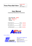
Conventional EIA (data) cameras can be used with the controller
The IV-S33MX controller can connect two EIA specification cameras using a converter. Just by replacing
the controller in the image processing section, you can achieve high-speed processing at decreased cost.
Controller
(IV-S33MX)
Converter
(IV-S30EA1)
EIA cameras
(commercially available)
Simple and speedy setting makes for easy setups
No need to create a measuring program. You just set the measuring conditions using the remote keypad.
In addition, the IV-S30 can automatically set the binary conversion threshold value and evaluation
conditions by just pressing the SET key.
NG displays and data are transferred quickly, for truly useful NG handling
The IV-S32MX/S33MX can check an NG image and a part’s NG history while measuring. Using the USB
communication bus, NG images can be transferred to a personal computer in less than 7 seconds. The
causes of NG products can be fed back to the design section, leading to quick improvements in the quality
of your products.
1-2
Outline
•
High-speed processing now possible using a high-speed camera and a partial-image capture
function
The IV-S30 (with the IV-S33MX controller) can use double and quad-speed cameras that employ
progressive type CCDs. Using SHARP’s unique, partial-image capture function, the IV-S30 offers
very high-speed image capturing. By selecting the best of five image capturing modes to match your
inspection and measurement conditions, this system helps reduce the processing time even further.
Full-image, full-line mode
Partial-image, half-line mode
Scan every line in the whole image
Scan half of the lines in just the specified area
IV-S31MX/32MX/33MX + standard camera
IV-S33MX + high-speed camera
IV-S33MX + high-speed camera
Note
Full-image, half-line mode
Partial-image, full-line mode and background half line mode
Scan half of the lines in the whole image
Scan every line in part of the image and scan
half of the lines in the rest.
IV-S33MX + high-speed camera
IV-S33MX + high-speed camera
Partial-image, full-line mode
Scan every line in the whole image
IV-S31MX/32MX/33MX + standard camera
IV-S33MX + high-speed camera
Note
* The partial-image modes are available when scanning 240 out of 480 vertical lines.
* Standard camera: IV-S30C1/C2, High-speed camera: IV-S30C3/C4
* Full-line mode: Scan odd and even lines. Half-line mode: Scan only the odd lines.
Note: The scan time will vary with the position of the partial image to scan. (In the cases given
above, there is a maximum of 0.4 ms of difference.)
•
Our high-precision gray search is also high speed
We normalize images to a 256 grayscale standard, and perform a high-precision gray search by
detecting features in sub-pixel units.
The IV-S30 can shorten this process using 9 ms high-speed processing * (IV-S33MX)
Gray search time
Conventional model Approx. 37 ms
(IV-S20)
IV-S31MX
Approx. 18 ms
IV-S32MX
Approx. 12 ms
IV-S33MX
Approx.
9 ms
* When the search area is 256 x 256 pixels, the model is 64 x 64 pixels, and contraction is to set 3.
•
Shorten the cycle time by connecting two cameras
The IV-S33MX can be simultaneously connected to two IV-S30C3/C4 high-speed cameras or two IVS30C1/C2 standard cameras. By connecting two cameras, your system can reduce the processing
time by positioning two areas at the same time, and then inspecting two areas at the same time. By
triggering the cameras at the same time, the system can capture two images, and display the images
above and below each other, or left and right.
Note: Combined use of a high-speed camera and a standard camera is not possible.
1-3
1
Outline
•
1
CCD trigger function does not need an external sensor
After a trigger window is setup, the IV-S30 does not need an external sensor if it is scanning moving
objects. To set up a trigger, you can select from binary image conversion, average density, and gray
search techniques. The gray search mode is useful for a workpiece for which you cannot easily establish the density range.
Feed direction
CCD trigger
•
Shutter speed freely set
The shutter speed can be set anywhere between 1/30 and 1/10000 second for each object type.
Practically, this means that the light level can be adjusted without changing the lighting equipment for
each object type. The random shutter function is used to close the shutter when a trigger event is
detected, so that precise still images of moving objects can be scanned.
•
Easily and automatically set threshold value and judgement criteria
Using the SET key, the IV-S33MX can automatically set the threshold values (binary conversion,
density difference, and edge width), that used to be set by entering numbers manually. To determine
the upper and lower limits of the OK and NG criteria, you only need to measure an OK workpiece.
Therefore, you no longer need to rely on skill, or experience to make accurate measurements at high
speed.
•
Histogram display of threshold values
In previous versions, the threshold values have only been displayed as numeric values. This model
adds a graphic display so that you can view the threshold values as an image.
THRESHOLD VAL AUTO-REG RESET
1U.LM
2L.LM
T C1 DRK
255(0∼255)
103(0∼255)
RATE
GRAY
SET=CHNG ESC=BACK SEL=CHNG TRG=FUNC
•
Automatic search reference images
The controller automatically searches for the maximum contrast area within the measurement area,
and detects it virtually instantly. Mistake-free work can now be performed quickly.
- This can be used for mis-collation checks of printed matters.
•
Simple measurements of position, detection of the same workpiece and counting quantities
By using the degree of match inspection functions for multiple workpieces and position measurement
for multiple workpieces, the controller can detect up to 128 workpieces in one image that meet or
exceed a specified degree of match with the reference image. The controller can count quantities and
measure the positions of workpieces that have complicated structures of light levels and are difficult to
convert to binary images.
1-4
Outline
•
Effective when checking for angular deviation, very good as a robotic eye
The controller can detect objects turned through a full 360˚ of orientation. It can inspect printing at
great angles off the main axis, and can be used in robotic inspection machines.
•
Integrated measuring programs allow the controller to be used for inspection and measurement immediately
Simple operations on the remote keypad let you select the desired measuring program to suit your
application. Since there is no need to develop measuring programs, this unit is easy set up and you
can start measuring products the same day you receive it.
- Various measuring programs
Positional deviation measurement, degree of match inspection, distance and angle measurement,
lead inspection, area measurement by binary conversion, counting by binary conversion, label measurement by binary conversion, point measurement, BGA/CSP inspection*, multiple position measurement, and multiple degree of match inspection.
* IV-S32MX/S33MX only.
•
You can cut your camera costs by using your current camera (IV-S33MX)
Two, commercially available EIA cameras can be connected using an IV-S30EA1 special converter.
This means that you can use your current EIA cameras the same as before, and just replace your
image processing section with the IV-S33MX. Installation and adjustment of lighting, camera, and
lenses is easy and can cut your costs.
•
Displays and transfers NG images while measurements are being made (IV-S32MX/S33MX)
The IV-S32MX/S33MX can check an NG image history (up to 128 images) while measuring, or simultaneously display a measured image and an NG image by splitting the screen. While measuring, the
controller can send NG images over the USB bus (12 Mbps) to a personal computer at high speed
(approximately 7 seconds per image). Since you can collect and analyze NG images in real time, the
NG rate can be decreased by finding the cause and making corrections immediately.
•
Integrated micro PC function
The IV-S30 has a micro PC function that allows it to determine unknown values by calculating the
inspected and measured results and then output signals to lamps and plungers. You can construct a
complete, simple inspection process with a single controller.
1-5
1
Outline
1-2 Controller
[1] Software version of the controllers
1
This manual describes the controllers (IV-S31MX/S32MX/S33MX) and their respective software versions
3.03C below.
[2] Differences between types of controllers
The controller models (IV-S31MX/S32MX/S33MX) have the following specifications.
Item
IV-S31MX
IV-S32MX
IV-S33MX
IV-S30J
IV-S31M
IV-S20
Number of object types handled
16
32
32
16
16
16
Maximum number of reference
images/ total number of images
300/3
600/8
600/8
200/2
300/3
200/3
Positional deviation
measurement
○
○
○
○
○
○
Degree of match
inspection
○
○
○
○
○
○
Area measurement
by binary
conversion
○
○
○
○
○
○
Object counting by
binary conversion
○
○
○
○
○
○
○
○
○
○
○
○
Point
measurements
○
○
○
○
○
○
Lead inspection
○
○
○
○
○
○
BGA/CSP
inspection
−
○
○
−
−
−
Multiple position
meansurement
○
○
○
○
○
−
Distance and angle
measurement
○
○
○
○
○
−
Communication method
RS232C/
RS422/USB
RS232C/
RS422/USB
RS232C/
RS422/USB
RS232C/
RS422
RS232C/
RS422/USB
RS232C/
RS422
Menu
Setting window
Menu tree
Setting window
Menu tree
Setting window
Menu tree
Setting window
Menu tree
Customize operation screen
Object identification
Measurement (labeling) by binary
program
conversion
Simplified menu
Standard menu
Standard menu
○
○
○
○
−
−
Standard camera
(IV-S30C1)
○
○
○
○
○
−
Micro camera
(IV-S30C2)
○
○
○
○
○
−
High-speed camera
(IV-S30C3)
−
−
○
−
−
−
Micro, high-speed
camera
(IV-S30C4)
−
−
○
−
−
−
EIA camera
(commercially
available)
−
−
○
−
−
−
Split display of two camera images
on the left and right sides of the
screen
−
−
○
−
−
−
Number of NG images that can be
stored (Maximum 128 images)
−
○
○
−
−
−
Connecting
camera
Calendar/timer
−
○
○
−
−
−
Size (WxDxH)
130x100x42
130x100x42
130x100x42
130x92x30
130x100x42
130x92x30
Polygonal window
32
32
32
32
Octagonal
(binary mask only)
−
CCD trigger
Binary/average
density/
Gray search/
edge detection
Binary/average
density/
Gray search/
edge detection
Binary/average
density/
Gray search/
edge detection
Binary/average
density/
Gray search/
edge detection
Binary/average
density/
Gray search
Binary/average
density
Gray search time*
18 ms
12 ms
9 ms
15 ms
18 ms
37 ms
X1 to 4
X1 to 5
X1 to 5
X1 to 4
X1 to 4
X0,X1 to 4
X5 to 7
X6, X7
X6, X7
X5 to 6
X5 to 7
X5 to 6
7W
7W
8W
7W
7W
250 mA
Object type be
Input terminal changed
block
External input
Power consumption
(" ": Compatible/available, "-": Not compatible/unavailable)
* The gray search times given above are true when the search area is 256 x 256 pixels, the
model is 64 x 64 pixels, and the contraction value is set to 3.
For other specifications, see pages 9-1 to 9-3 in "Chapter 9: Specifications."
1-6
Outline
1-3 Measurement program
The IV-S30 integrates the following eight measurement programs: Positional deviation,degree of match
inspection, lead inspection, BGA/CSP inspection (IV-S32MX/S33MX), area measurement by binary
conversion, object counting by binary conversion, object identification (labeling) measurements by binary
conversion, multiple position measurement, multiple degree of match inspection, point measurements
and distance and angle measurement. You can select operating condition parameters to suit your
application of the IV-S30.
A description of each screen area is shown below.
[1] Positional deviation measurement
Purpose
The gray scale search function and edge detection function* make possible measuring
positional deviation as well as the absolute position.
- It is also possible to detect the position of sub-pixel units with great accuracy.
- A rotation angle of 360° can be detected. (When a one point gray search is selected).
Application Used to determine the position of machine parts and substrates.
[Determining the location of the positioning (the fiducial mark) mark that
identifies the position of the substrate]
(1) 1 point search: Detecting the deviation in position in X and Y directions
Reference image: Center coordinates (X1,Y1)
Inspection Image: Center coordinates (X2,Y2)
[Measured result]
Center coordinates: (X2,Y2)
Amount of deviation: X2-X1, Y2-Y1
Y2-Y1
Search area
X2-X1
(2) 2 point search: Determining positional deviation in X and Y directions as well
as rotational deviation
Reference image a: Center coordinates (Xa1,Ya1)
Inspection image a: Center coordinates (Xa2,Ya2)
Reference image b: Center coordinates (Xb1,Yb1)
Ya2-Ya1
Inspection image b: Center coordinates (Xb2,Yb2)
Example
θ
Search area
(image a)
Yb2-Yb1
Xa2-Xa1
Anglar deviation: θ
[Measured results]
- Center coordinates of image a: (Xa2,Ya2)
- Amount of deviation of image a: Xa2-Xa1, Ya2-Ya1
- Center coordinates of image b: (Xb2,Yb2)
- Amount of deviation of image b: Xb2-Xb1, Yb2-Yb1
- Deviation angle: θ
Xb2-Xb1 Search area (image b)
* Gray scale search / edge detection function
Gray scale search: Compares a workpiece image with the 256-level gray-scale
reference image to find an area that matches the reference image.
- See G-6.
Edge detection: Finds the boundary between light and dark areas in an image.
- See G-3.
- The deviation angle θ, determined in the 2-point search, is used to readjust the
rotation of the image for measurements 1 to 4.
1-7
1
Outline
[2] Degree of match inspection
Compare a good criterion image to a test image by inspecting matching levels using the
gray scale search function. (Determine whether the part is acceptable or NG by checking
similarities between the criterion image and the workpiece (test) image.)
A matching level comparison using binary images is also possible.
Detect positional deviation of labels, detect contamination of different parts, inspect the
Appli- mounting of electronic parts on PC boards, detect mis-prints, inspect for missing electric
cation
parts such as terminals, and simple letter inspection.
[Detecting label deviations on packages]
Search area
for positioning
Search area
for positioning
Criterion image
for positioning
SERIAL NO.
8F053G26
MODEL
IV-S30
Criterion image
for positioning
SERIAL NO.
8F053G26
MODEL
IV-S30
Example
Criterion image
for measuring object
Criterion image
for measuring object
▲Good label
▲NG label
[Measured results]
- Degree of match compared with the reference image
- Detected coordinates (X/Y) of the measurement image.
- Light level in the measured image (average light level/absolute value of difference)
- Inspection procedure
1 Conduct a gray scale search of the criterion image position
2 Correct the position of the object being measured from the coordinates for the
criterion image obtained in item 1 above.
3 If the matching level of the test image is low, the IV-S30 can determine that the
label position is NG.
[3] Lead inspection
Purpose
Based on positional information obtained from the gray scale search function, inspect the
condition of the IC leads and connector pins. (No. of lead pins that can be detected in one
image: Max. 128.)
Application
Inspect the IC leads and connector pins
[Inspect the layout of the IC leads and connector pins]
K1
D2
K2
K3
Reference line
Example
W0
W1
W2
L3
K0
D1
L1
D0
L2
Lead measurement limit line
Lead
L0
1
Purpose
[Lead inspection]
- Number of leads K
- D0 to D2: Distance
between leads
- W0 to W3: Lead width
- L0 to L3: Lead length
W3
- Inspection procedure
1 Determine the measurement points (K0 to K3) from the mid points of the leads and
the reference line.
2 Calculate the distances between the leads (D0 to D2) using the measurement points.
3 Calculate the lead lengths (L0 to L3) from the measurement points (K0 to K3) toward
the lead measurement limit line.
4 Calculate the lead widths (W0 to W3) centering the measurement points.
1-8
Outline
[4] BGA/CSP inspection (IV-S32MX/S33MX)
Purpose
Measure the center of gravity, area of each object, number of objects, and fillet diameter
using the object identification function after binary conversion.
AppliInspecting BGA/CSP solder balls.
cation
[Measurement of 6 balls]
Object 0
Object 1
Object 2
[Measured results]
- Number of objects: K
- Area of each object: R0 to R127
- Distance between centers of gravity:
(DX0, DY0) to (DX127, DY127)
- Fillet diameters: FX, FY
Example
Object 3
Object 4
Object 5
- Inspection procedure
Image
capture
Binary
conversion
Area of each
object
Object identification
(numbering)
Measure centers
of gravity
Fillet diameters
Ball size
Distance between centers
of gravity for pairs of balls
Distance between balls
Number of balls
[5] Area measurement by binary conversion
Purpose
Detect the existence/absence and size of a workpiece when the workpiece is one point
or "measurement position is fixed." - Convert the specified pixel area to binary values and measure the size of the white
area.
Check for the existence of bearings inserted by a bearing insert machine, prevent conAppli- tamination of different parts in automobile production lines, determine the type of watercation proof caps, check for the existence/absence of bottle labels, inspect the cuircuit traces on
PWBs, check for the presence of grease, check for existence of frozen foods.
[Measured result]
- Workpiece area
Workpiece
Example
- Inspection procedure
Capture image
Convert to binary values
1-9
Measure (area)
1
Outline
[6] Object counting by binary conversion
1
Purpose
Checks the number of objects (max. 3000 pcs.) when there is more than one object in an
image arranged arbitrary.
- When the specified pixel field has been converted to a binary image, the white areas
are measured or identified as separate objects and counted.
Application
Counting pieces of food or parts
Example
[Measured result]
- Number of workpieces/total area
size
Workpiece
- Inspection procedure
Convert to binary values
Capture image
Measure (quantity, total area size)
[7] Object identification (labeling) by binary conversion
Purpose
When there are several objects and the measuring position is arbitrary, the presence or
absence of objects and the size of the objects can be determined.
- The specified pixel area is converted to a binary image. The number of objects, total size
of the white area (the objects) and the area, center of gravity, main axis angle, fillet
diameter, center point, and circumference of each white area can be measured.
Application
Counting the number of food products or parts, measuring the sloped angle or center of
gravity of parts, and measuring the size of food products.
[Measurement of 6 objects]
No.1
No.2
No.3
Objects
No.4
No.5
No.6
Example
[Measured result]
- Object identification (numbering),
number of objects present, total
area.
- Area of each object (No.1 to No.
6), center of gravity, main axis
angle, fillet diameter,
circumference, and center point of
each object. - Inspection procedure
Image capture
Convert to binary values
Object identification (numbering)
Measurement (area, gravity center, main axis angle,
fillet diameter, circumference, and center point)
1-10
Outline
[8] Point measurements
Purpose
The presence or absence of target objects is examined.
- A simple black or white evaluation is made in the specified pixel area of binary
images.
- The light level in the specified pixel area is averaged, and a decision is made
whether or not it is within the specified lightness range in gray scale images.
Checking the presence or absence of packed parts, inspecting the working
Applications condition of LEDs or fluorescent character display tubes, and sorting household
electric appliances.
[Inspection at 6 points]
Number of points (max.)
: 128 points at average light levels
256 points in binary images
Point size: 2 m x 2n pixels
(m, n = 1 to 16)
Example
- Inspection procedures
Image capture
Binary
conversion
Black/white evaluation
of points
Average light
level
Light level evaluation
of points
1-11
1
Outline
[9] Multiple position measurement
1
The IV-S30 can detect up to 128 workpieces whose images exceed the specified matching
level (gray search) or threshold value (edge detection) compared with the reference
image.
Purpose - The positional deviation measurement needs to have a number of positions registered for
measurement. However, this measurement only requires you to register one position and
reduces the set up time.
Applica- Measure the position of workpieces with a complicated light level that cannot be converted
into binary images.
tion
● Gray search
Reference image
Four workpieces
detected
[Measured results]
- Number of images detected
- Coordinates and degree of match detected for each image
● Edge detection
Example
[Measured results]
- Number of points detected
- Coordinates detected for each points
L1
L2
L3
This is useful for obtaining the distance between the coordinates of a position.
- L1 to L3 can be calculated by measuring distances and angles.
1-12
Outline
[10] Multiple degree of match inspection
Using the gray search function, the IV-S30 can detect up to 128 workpieces whose
Purpose captured image exceeds the required degree of match with the reference image.
Applica- Inspect (or count) workpieces that have complicated light levels and cannot be converted
into binary images
tion
Reference image
Four workpieces
detected
Example
[Measured results]
- Number of images detected
- Degree of match, density (average/absolute difference), and detected coordinates
[11] Distance and angle measurement
Purpose
Measure the distance and angle of two points using the center detection function in a gray
scale search and the edge detection function, as well as center of gravity detection by
functions.
- This function can measure the following distances and angles: distance between two points,
X coordinate distance, Y coordinate distance, the angle between three points, the horizontal
angle of two points, and the vertical angle of two points.
- The following points and lines can be set: center point, circle center point, gravity center,
point where two straight lines cross, line passing through two points.
Application
Measurement of mounted electronic parts
[Measuring IC packages]
Criterion image a
Search area
(criterion image b)
Example
Search area
(criterion image a)
Criterion image b
Register criterion image a and b by matching edges of the IC package.
- Measurement procedures
1 Find the center points of criterion images a and b using a 2-point gray scale search.
2 Determine the distance between the two center points.
1-13
1
Precautions for Use
Chapter 2: Precautions for Use
Pay attention to the points below when handling the IV-S30.
(1) Installation
- Each device in the IV-S30 system must be installed in an environment as specified in this manual.
(Operating ambient temperature: 0 to 45˚C, operating ambient humidity: 35 to 85%RH (noncondensing.))
- Do not install the devices in the following locations. Installation in any of these locations may
cause electrical shock, fire, or malfunction of the devices.
1. Places exposed to direct sunlight
2. Places with exposed to corrosive gases
3. Places with excessive amounts of dust, salt, or metal powder in the air.
4. Places exposed to water
(2) Mounting
Make sure to tighten the mounting and terminal screws securely and check everything before
supplying power. A loose screw may cause faulty operation.
(3) Power source
- Do not use the IV-S30 (power supply for the controller) power supply with any other equipment.
- Do not turn OFF the power while the menu is displayed or while communicating with external
equipment. Turning OFF the power may erase the data settings.
(4) Measurement settings
Make sure to specify 4000 ms (4 seconds) or less for the measurement processing time on each
measurement item (MEASUREMENT 0 CAMERA 1, MEASUREMENT 0 CAMERA 2, and
MEASUREMENT 1 to 4). For example, if the various tasks require 7000 ms of measurement
processing time, assign 3500 ms to MEASUREMENT 1 and 3500 ms to MEASUREMENT 2 so that
each of the assigned processing times is less than 4000 ms.
If the measurement processing time exceeds 4000 ms, the IV-S31MX/S32MX/S33MX assumes that
an abnormal operation has occurred and may try to reset the system.
(5) Data saving
- The data set by using the remote keypad is temporarily stored in the memory (RAM) of the IVS30. However, it is not stored in the flash memory yet. Therefore, make sure to save the data
settings before returning to the operation screen from any condition settings menu by pressing
the SET key. If you do not save the data, the data will disappear when you turn OFF the power
to the IV-S30 controller.
- We recommend that you save the data settings and reference images on a floppy diskette using
the IV-S30SP parameter setting support software for the IV-S30.
(6) Storing the devices
Do not put any object on top of any of the devices, or the device may malfunction.
(7) Maintenance
Be careful not to get any dirt or stains on the CCD surface or camera lens. This may cause mis
measurement.
2-1
2
System Configuration
Chapter 3: System Configuration
3-1 Basic system configuration
[1] When the IV-S31MX/S32MX is used as the controller
Monitor
Personal
computer
Input/output
IV-09MT, IV-10MT etc.
With either an EIA or
NTSC compatible video input terminals
・Programmable controller
・Limit switch
・Warning lamp, etc.
Parallel I/F
Conversion
connector
(Accessory for the
IV-S31MX/S32MX)
3
Programmable controller
Serial I/F
Parameter setting
support software for
the IV-S30:
IV-S30SP
USB
RS232C
RS422
Monitor cable
(Accessory for the
IV-S31MX/S32MX)
Power
supply
(24 VDC)
Controller
(IV-S31MX/S32MX)
Remote key pad
(IV-S30RK1)
Camera cable
IV-S30KC3
IV-S30KC5
IV-S30KC7
-
Camera cable
IV-S30KC3
IV-S30KC5
IV-S30KC7
LED lighting
equipment
(IV-60LD)
Camera Camera lens
(IV-S30C2) (IV-S20L16)
Micro camera
(IV-S30C2)
φ17lens
(purchase)
A maximum of two cameras can be connected to the IV-S31MX/S32MX.
An IV-S20C1 camera (for the IV-S20) also can be connected using a camera conversion
cable (IV-S30HC).
Product lines
Item name
Standard
Camera
Micro
Camera cable
Camera lens
Remote keypad
Parameter setting support
software
Image processing library
Monochrome monitor
LCD monitors
Model name
IV-S30C1
IV-S30C2
IV-S30KC3
IV-S30KC5
IV-S30KC7
IV-S20L16
IV-S30RK1
Specification or details
Camera main housing (without lens or camera cable)
Camera main housing (without lens or camera cable)
Cable for IV-S30C1/C2 camera, 3 m
Cable for IV-S30C1/C2 camera, 5 m
Cable for IV-S30C1/C2 camera, 7 m
C mount lens with a 16 mm focal length
Keys for remote entry
IV-S30SP
Runs on Windows95/98/NT4.0
IV-S30LB1
IV-09MT
IV-10MT
IV-10MTV
Runs on Windows95/98/NT4.0
Monochrome 9 inch monitor
Bare chassis type
Model with a mounting frame
Model with a built-in remote keypad and a mounting
frame
Integrated light source and controller in one housing
IV-10MTK
LED lighting equipment
-
IV-60LD
For details about the IV-S30SP, IV-S30LB1, IV-09MT, IV-10MT, and IV-60LD, see the individual
instruction manuals.
3-1
System Configuration
[2] When the IV-S33MX controller is used
Monitor
Personal
computer
Input/output
IV-09MT, IV-10MT etc.
With either an EIA or
NTSC compatible video input terminals
Conversion
connector
(Accessory for the
IV-S33MX)
3
・Programmable controller
・Limit switch
・Warning lamp, etc.
Parallel I/F
Programmable controller
Parameter setting
support software for
the IV-S30:
IV-S30SP
Serial I/F
USB
RS232C
RS422
Monitor cable
(Accessory for the
IV-S33MX)
Power
supply
(24 VDC)
Monitor cable
(Accessory for the
IV-S33MX)
Remote key pad
(IV-S30RK1)
Camera cable
IV-S30KC3
IV-S30KC5
IV-S30KC7
Camera cable
IV-S30KC3
IV-S30KC5
LED lighting
equipment
(IV-60LD)
High-speed
camera
(IV-S30C3)
Camera cable
IV-S30KC3
IV-S30KC5
IV-S30KC7
φ17 lens
(purchase)
φ17 lens
(purchase)
CAMERA2
FG
0V
+24V
POWER
IV-S30EA1
CAMERA1
1
-
Micro, high-speed camera
(IV-S30C4)
CONTROLLER
2
-
Camera lens
(IV-S20L16,etc)
Micro camera
(IV-S30C2)
Camera cable
IV-S30KC3
IV-S30KC5
Main interface cable
(IV-S30EA1 accessory)
Camera lens
(IV-S20L16,etc)
Camera
(IV-S30C1)
Camera converter
(IV-S30EA1)
EIA camera
(Maximum of two -commercially available)
A maximum of two cameras of the same type can be connected to the IV-S33MX.
Mixed use of different camera types (IV-S30C1/C2, IV-S30C3/C4, and EIA cameras) is not
supported.
The IV-S30KC7 camera cable cannot be used with the IV-S30C3/C4 high-speed camera.
The IV-S20C1 camera for the IV-S20 can also be connected using a camera conversion cable
(IV-S30HC).
3-2
System Configuration
Product configuration
Item name
Standard
Micro
Camera
High-speed
Micro, highspeed camera
Camera converter
Camera cable
Camera lens
Remote keypad
Parameter setting support
software
Image processing library
Monochrome monitor
LCD monitors
Model name
Specification or details
IV-S30C1
Camera main housing (without lens or camera cable)
IV-S30C2
Camera main housing (without lens or camera cable)
IV-S30C3
Camera main housing (without lens or camera cable)
IV-S30C4
Camera main housing (without lens or camera cable)
IV-S30EA1
IV-S30KC3
IV-S30KC5
IV-S30KC7
IV-S20L16
IV-S30RK1
Connect up to two EIA cameras (commercially available)
Cable for IV-S30C1/C2/C3/C4 camera, 3 m
Cable for IV-S30C1/C2/C3/C4 camera, 5 m
Cable for IV-S30C1/C2 camera, 7 m
C mount lens with a 16 mm focal length
Keys for remote entry
IV-S30SP
Runs on Windows95/98/NT4.0
IV-S30LB1
IV-09MT
IV-10MT
IV-10MTV
Runs on Windows95/98/NT4.0
Monochrome 9 inch monitor
Bare chassis type
Model with a mounting frame
Model with a built-in remote keypad and a mounting
frame
Integrated light source and controller in one housing
IV-10MTK
LED lighting equipment
-
IV-60LD
For details about the IV-S30SP, IV-S30LB1, IV-09MT, IV-10MT, and IV-60LD, see the individual
instruction manuals.
3-3
3
System Configuration
3-2 System configuration examples
This section outlines the system configurations for measurement using an external trigger, such as
measurement using a photo sensor, measurement using CCD trigger, and measurement triggered by a
command from a personal computer.
See "Setting the Input/Output Conditions" in the IV-S31MX/S32MX/S33MX User’s Manual (Function
and Operation).
[1] System configuration example for measurement triggered by an external
trigger, such as a photo sensor
Camera 1 (image)
Camera 2 (image)
Monitor
Remote key pad
CAMERA1
VIDEO
USB
RS232C/RS422
CAMERA2
REMOTE
Controller
POWER
OUTPUT
Y0
Y1
X0
Y2
X1
Y3
X2
Y4
X3
Y5
X4
Y6
X5
Y7
X6
READY COM
X7
0V
COM +24V
IV-S3*M
INPUT
Power supply (24 VDC)
External trigger
(a photo sensor or proximity
sensor, etc.)
Warning lamp etc.
External
output
Object type selection switch
(2) When a programmable controller is connected
- Purpose/application
Measurement is started by an external trigger (a photo sensor or proximity sensor), and the
measurement data is output to a programmable controller. The object type number is selected
by the programmable controller.
Camera 1 (image)
Camera 2 (image)
Monitor
Remote key pad
Data (computer link)
VIDEO
CAMERA1
USB
RS232C/RS422
CAMERA2
REMOTE
Controller
POWER
OUTPUT
Y1
Y2
X1
Y3
X2
Y4
X3
Y5
X4
Y6
X5
Y7
X6
READY COM
X7
0V
COM +24V
INPUT
IV-S3*M
Power supply
(24 VDC)
X0
Programmable
controller
Y0
3
(1) When IV-S30 is used in a stand-alone mode
- Purpose/application
Measurement is started by an external trigger (a photo sensor or proximity sensor), and the
measurement result is output externally (warning lamp). The object type number is selected by
an external switch.
External trigger
(a photo sensor or proximity
sensor, etc.)
Object type selection
(parallel I/F)
3-4
System Configuration
(3) When a personal computer is connected
- Purpose/application
Measurement is started by an external trigger (a photo sensor or proximity sensor etc.), and the
measurement data is output to a personal computer. The object type number is selected by the
personal computer.
Camera 1 (image)
Camera 2 (image)
Monitor
3
Personal
computer Object type selection,
data
VIDEO
CAMERA1
USB
RS232C/RS422
CAMERA2
REMOTE
Controller
POWER
OUTPUT
Y0
Y1
X0
Y2
X1
Y3
X2
Y4
X3
Y5
X4
Y6
X5
Y7
X6
READY COM
X7
0V
COM +24V
IV-S3*M
INPUT
Power supply
(24 VDC)
External trigger
(a photo sensor or proximity
sensor etc.)
[2] System configuration example for measurement triggered by the internal CCD
sensor trigger
The internal CCD trigger can be used with camera 1, but with camera 2.
(1) When IV-S30 is used in a stand-alone mode
- Purpose/application
Measurement is started by a CCD trigger, and the measurement result is output externally
(warning lamp etc.). In this case, sampling operation is automatically started.
Camera 1 (image + CCD trigger)
Camera 2 (image)
Monitor
Remote key pad
CAMERA1
USB
RS232C/RS422
CAMERA2
REMOTE
POWER
OUTPUT
Y2
X1
Y3
X2
Y4
X3
Y5
X4
Y6
X5
Y7
X6
READY COM
X7
0V
COM +24V
IV-S3*M
INPUT
3-5
Y1
External
output
X0
Warning lamp etc.
Y0
Power supply (24 VDC)
VIDEO
Controller
System Configuration
(2) When a programmable controller is connected
- Purpose/application
Measurement is started by a CCD trigger (sampling start input: a photo sensor etc.), and the
measurement data is output to a programmable controller. The object type number is selected by
the programmable controller.
Camera 1 (image + CCD trigger)
Camera 2 (image)
Monitor
3
Data (computer link)
CAMERA1
VIDEO
USB
RS232C/RS422
CAMERA2
Remote key pad
REMOTE
Controller
POWER
OUTPUT
Y0
Y1
X0
Y2
X1
Y3
X2
Y4
X3
Y5
X4
Y6
X5
Y7
X6
READY COM
X7
0V
COM +24V
INPUT
IV-S3*M
Programmable
controller
Power supply
(24 VDC)
Start sampling input
(a photo sensor or proximity
sensor etc.)
Object type selsection
(parallel I/F)
(3) When a personal computer is connected
- Purpose/application
Measurement is started by a CCD trigger (sampling start input: personal computer), and the
measurement data is output to a personal computer. The object type number is selected by the
personal computer.
Camera 1 (image + CCD trigger)
Camera 2 (image)
Monitor
Personal
computer Start sampling input
Object type selection, data
CAMERA1
USB
RS232C/RS422
CAMERA2
REMOTE
POWER
OUTPUT
Y1
X0
Y2
X1
Y3
X2
Y4
X3
Y5
X4
INPUT
Y6
X5
Y7
X6
READY COM
X7
0V
COM +24V
IV-S3*M
3-6
Y0
Power supply
(24 VDC)
VIDEO
Controller
System Configuration
[3] System configuration example for measurement triggered by a command from a
personal computer
- Purpose/application
Measurement is started by a trigger from a personal computer, and the measurement data is
output to the personal computer. The object type number is selected by the personal computer.
Camera 1 (image)
Camera 2 (image)
3
Personal
computer
Command,
Monitor
response
Remote key pad
VIDEO
CAMERA1
USB
RS232C/RS422
CAMERA2
REMOTE
Controller
POWER
OUTPUT
Y0
Y1
X0
Y2
X1
Y3
X2
Y4
X3
Y5
X4
Y6
X5
Y7
X6
INPUT
READY COM
X7
0V
COM +24V
IV-S3*M
Power supply (24 VDC)
Table of combinations of controllers, camera cables, and cameras.
Compatible cable
Controller+Camera
IV-S31MX
IV-S32MX
IV-S33MX
+
IV-S30C1
IV-S30C2
IV-S30C3
IV-S30C4
IV-S33MX+Camera converter (IV-S30EA1)
+Commercially available EIA camera
IV-S33MX
+
3-7
IV-S30KC3
IV-S30KC5
IV-S30KC7
IV-S30KC3
IV-S30KC5
Main interface cable
(IV-S30EA1 accessory)
Part Names and Functions
Chapter 4: Part Names and Functions
This section describes the names and functions of the controller, camera (camera body, camera
converter, camera lens and camera cable), and the remote keypad which comprise the IV-S30 system.
See section in Chapter 5 "Connection and Installation Methods" for details about the housing brackets,
camera angle bracket and conversion connector.
4-1 Controller (IV-S31MX/S32MX/S33MX)
9 Frame ground terminal
2 Power terminal block
1 I/O terminal block
S*.** mark
(Software version *.**)
INPUT
X0
Controller (front)
Y0
X1
Y1
X2
Y2
X3
Y3
X4
Y4
X5
Y5
X6
Y6
X7
Y7
COM +24V
READY COM
OUTPUT
0V
IV-S3*MX
POWER
3 Power lamp (POWER)
VIDEO
CAMERA1
CAMERA2
USB
RS232C/RS422
REMOTE
0 Communication connector (USB)
42
Controller (side)
4 Monitor connector (VIDEO)
8 Remote key pad connector
(REMOTE)
5 Camera 1 connector (CAMERA1)
7 Communication connector
(RS232C/RS422)
6 Camera 2 connector (CAMERA2)
Name
I/O terminal block
INPUT: X0 to X7, C (+)
1 OUTPUT: Y0 to Y7,
READY, COM
2 Power terminal block
(+24V, 0V)
3 Power lamp (POWER)
Function
This block has 8 input terminals and 9 output terminals.
- External devices are connected to these terminals for input and
output (parallel I/F). - See page 5-16.
Commercially available constant-voltage power supply (24 V DC ±
10%, 500 mA or more) is connected here. - See page 5-15.
When the power is applied to the controller, the green lamp will light.
A monitor is connected here.
Monitor connector
4 (VIDEO)
- The monitor connector is an RCA jack.
Camera 1 connector
The camera cable connector is connected here.
5
(CAMERA1)
- The camera connected to the CAMERA 1 position is camera 1,
and the camera connected to the CAMERA 2 position is camera 2.
6 Camera 2 connector
(CAMERA2)
This connector is used to connect a personal computer for communiCommunication connector
cations (general purpose serial I/F) or to connect a programmable
7 (RS232C/RS422: 9-pin Dsub female, rock screw M2.6) controller for a computer link. - See page 5-19.
Remote key pad connector
The remote key pad connector is used to make selections from the
8 (REMOTE)
menues on the screen (to set parameters). It is connected here.
9 Frame ground terminal
0 Communication connector
(USB)
Be sure to ground the housing frame ground terminal together with
the frame ground of the constant-voltage power supply in accordance with class 3 grounding procedures. -See page 5-15.
This connector is used to connect a cable to a USB port on a personal computer.
- The USB port only functions with Windows 98.
4-1
4
Part Names and Functions
4-2 Camera
[1] Camera
(1) Standard camera (IV-S30C1)
Lock screw (for securing the lens holder)
2 Cable connector
CCD section
⇒A
1 Lens holder
Front view (view A) of the CCD
Name
Function
1
Lens holder
The holder is used to make fine adjustment to the distance (back plane focus) between the CCD section and camera lens using a focus fixed lens.
(The distance has been adjusted before shipment. Usually, it does not
need to be adjusted.)
- To adjust it, loosen the upper lock screw, and turn the lens holder counter-clockwise. The maximum allowable distance is 1.5 mm.
2
Cable
connector
4
Connect this connector to the camera cable (IV-S30KC3/KC5/KC7).
- To connect a standard camera (IV-S30C1), use the IV-S31MX/S32MX/S33MX controller and
camera cable (IV-S30KC3/KC5/KC7) shown above.
(2) Micro camera (IV-S30C2)
2 Camera body
1 Camera head
Head cable
CCD section
φ
17
m
Cable connector
Cable length: 1 m
Camera head
installation section
Name
1 Camera head
2 Camera body
m
Lens mount section
(M 15.5 x 0.5 mm)
Function
Install a (commercially available) lens.
- The maximum external diameter of the camera head is φ17 mm,
and the one for lens mount is M 15.5 x 0.5 mm.
Connect to the camera connector of the camera cable (IV-S30KC3/
KC5/KC7).
- To connect a micro camera (IV-S30C2), use the IV-S31MX/S32MX/S33MX controller and camera
cable (IV-S30KC3/KC5/KC7) shown above.
4-2
Part Names and Functions
(3) High-speed camera (IV-S30C3)
Lock screw (for securing the lens holder)
2 Cable connector
CCD section
⇒A
1 Lens holder
Front view (view A) of the CCD
Name
Function
1
Lens holder
The holder is used to make fine adjustment to the distance (back plane focus) between the CCD section and camera lens using a focus fixed lens.
(The distance has been adjusted before shipment. Usually, it does not
need to be adjusted.)
- To adjust it, loosen the upper lock screw, and turn the lens holder counter-clockwise. The maximum allowable distance is 1.5 mm.
2
Cable
connector
Connect this connector to the camera cable (IV-S30KC3/KC5).
Note: This cable cannot be used to connect the IV-S30KC7.
- To connect a high-speed camera (IV-S30C3), use the IV-S33MX controller and camera cable (IVS30KC3/KC5) shown above.
Note: Do not connect a high-speed camera (IV-S30C3) to the IV-S31MX/S32MX controller.
(4) Micro, high-speed camera (IV-S30C4)
2 Camera body
Head cable
1 Camera head
CCD section
φ
17
m
Cable connector
Cable length: 1 m
Camera head
installation section
Name
1 Camera head
2 Camera body
m
Lens mount section
(M 15.5 x 0.5 mm)
Function
Install a (commercially available) lens
- The maximum external diameter of the camera head is ø17 mm, and
the one for lens mount is M 15.5 x 0.5 mm.
Connect to the camera connector of the camera cable (IV-S30KC3/KC5)
Note: This cable cannot be used to connect the IV-S30KC7.
- To connect micro, high-speed camera (IV-S30C4), use the IV-S33MX controller and camera
cable (IV-S30KC3/KC5) shown above.
Note: Do not connect micro, high-speed camera (IV-S30C4) to the IV-S31MX/S32MX controller.
4-3
4
Part Names and Functions
[2] Connects to commercially available EIA cameras
(1) Camera converter (IV-S30EA1)
Use the IV-30EA1 camera converter when you want to use a commercially available EIA camera with
the IV-S33MX controller.
2 EIA camera connector 2: CAMERA2
1 EIA camera connector 1: CAMERA1
CAMERA2
CAMERA1
4
6 Frame ground terminal
(FG)
MODE
EXT
IV-S30EA1
POWER
+24V
0V
FG
INT
5 Power terminals
(+24 V, 0 V)
3 Mode switch: MODE
7 Power indicator:
POWER
CONTROLLER
4Controller connector:
CONTROLLER
Name
EIA camera connector
1 1: CAMERA1
EIA camera connector
2 2: CAMERA2
3 Mode switch: MODE
Controller connector:
4 CONTROLLER
Power terminals
5 (+24 V, 0 V)
Frame ground terminal
6 (FG)
Power indicator:
7 POWER
Function
Connect an EIA camera (commercially available). Any camera
connected to CAMERA1 will be camera 1, and any camera connected
to CAMERA2 will be camera 2.
Note: Do not connect SHARP's special IV-S30C1/C2/C3/C4 camera.
Select the camera synchronization mode from EXT and INT. Use a
thin pointed object such as a ballpoint pen.
- EXT = Lets you use an EIA camera with an externally
synchronized mode (a synchronizing signal is sent from
the IV-S33MX to the EIA camera).
- INT = Lets you use an EIA camera with an internally
synchronized mode.
Connect to the main housing cable (supplied with the IV-S30EA1, see
the next page) to the IV-S33MX controller.
Connect to any commercially available constant voltage DC power
supply (24 VDC±10%, 500 mA or more)
This terminal is commoned with the enclosure. When the EIA camera
is connected to the controller using a shielded cable, the EIA camera
housing will be electrically connected to this terminal.
When power is supplied to the IV-S30EA1, this lamp will light green.
- To connect the IV-S30EA1 camera converter to the IV-S33MX controller, use the cable supplied
with the IV-S33MX (see the next page).
Note: The IV-S30EA1 camera converter cannot be connected to the IV-S31MX/S32MX controller.
4-4
Part Names and Functions
(2) Cable to connect the camera converter to the controller (supplied with the IV-S30EA1)
2 CAMERA 2 connector
3 Converter connector
2
1
1 CAMERA1 connector
Name
Function
1 Camera 1 connector Connect to the CAMERA 1 and CAMERA 2 connectors on the IVS33MX controller.
2 Camera 2 connector
Converter connection
Connect to the controller side connector on the IV-S30EA1.
3 connector
REMOTE
IV-S3*MX
0V
USB
RS232C/RS422
CAMERA2
VIDEO
CAMERA1
COM +24V
READY COM
Y7
X6
Y6
X5
Y5
X4
INPUT
OUTPUT
Y4
X3
Y3
X2
Y2
X1
Y1
1
X0
CAMERA1
IV-S30EA1
POWER
Y0
CAMERA2
+24V
0V
Controller
Main interface cable
IV-S31MX/S32MX/S33MX
FG
CONTROLLER
2
X7
POWER
(3) Connection example using an EIA camera
Camera converter
IV-S30EA1
4-5
Commercially available
EIA cameras
4
Part Names and Functions
[3] Camera lens (IV-S20L16)
1 Focus
C
0.05m
Lock knob 2 (for fixing the focus)
1. 6
focus
∞
TV LENS 1:1.6 16mm
Lock knob 1 (for fixing the iris)
2 Iris
5.5 mm
(Movable range for focus adjustment)
Name
4
1
Focus
2
Iris
Function
To focus an image
-The focall enght (distance from an object) is 50 mm to infinity (from the front
of lens).
To adjust the image brightness.
-The iris a perture can be set from 1.6mm to closed.
[4] Camera cable (IV-S30KC3/KC5/KC7)
1 Camera connector
(Threaded type)
2 Controller connector
(Quick-connect type)
Cable length
IV-S30KC3: 3 m
IV-S30KC5: 5 m
IV-S30KC7: 7 m
Name
Function
1
Camera
connector
Connect to a connector of camera cable (IV-S30C1/C2/C3/C4).
Note: The IV-S30KC7 cannot be connected to the IV-S30C3/C4.
2
Controller
connector
Connect to camera 1 connector or camera 2 connector of the controller
(IV-S31MX/S32MX/S33MX).
4-6
Part Names and Functions
4-3 Remote keypad (IV-S30RK1)
Connector
- Connected to the controller
(IV-S31MX/S32MX/S33MX)
Cable length 3 m
4 SEL change key
1 Direction keys
(up, down, left and right)
5 TRG/BRT change key
2 SET key
Dimensions (mm)
130 (W) × 61 (D) × 22.5 (H)
Key name
Direction keys*
1 (up, down, left
and right)
3 ESC key
Function
Description
Selecting an item on a
menu screen
Select an item with the up, down, left and right
keys.
Setting a window
Set each coordinate.
Setting a value
- Select a digit or an item with the left and right
keys, and then specify a value with the up and
down keys.
- Specify a value with the up, down, right and
left keys.
To enter nested menus
2 SET key
3 ESC key
4 SEL key
Determine a highlighted
item
Determine the setting
value
Returning a setting to its On the REG-COND screen,
original state before be- - Press the left arrow key + ESC key to change
ing changed
between a display of all items and just one
Returning to the previous item at a time.
menu
- When the screen is changed from "Through"
to "Freeze," the IV-S30 will capture an image.
Use to select the display
- Change the brightness of the image displayed
of object images:
on the screen.
choose between "F"
On the setting screen,
(Freeze) and "T"
(Through) and between - Press the left arrow key and the SEL key to
change between Through and Freeze.
"BRT" (bright) and
- Press the right arrow key and the SEL key to
"DRK" (dark).
change between Bright and Dark.
Start measurement input
5 TRG/BRT key
Press this key on the operation screen, and a
new measurement is triggered.
Move the cursor to the
function menu at the
upper area.
Displays popup menu.
* The direction keys have an auto-repeat function.
4-7
4
Connection and Installation Methods
Chapter 5: Connection and Installation Methods
5-1 Installation conditions
[1] Lighting equipment
Lighting for the workpieces is an important factor in image processing. The lighting conditions affect the
measurement results. Select the proper lighting equipment.
- Make sure there is uniform illumination of the whole measurement field where object images will be
taken.
- Use flicker-free lighting equipment, such as a high frequency fluorescent lamps or halogen lamps.
- Consult us about the right lighting equipment for your application.
(1) Backlighting
Light should uniformly illuminate the field behind an object, so that the IV-S30 measure the object with
it's shadow. Since the shadow picture will be converted to binary values, reliable measurements can
be executed.
5
Example:
IV-S30C1
or similar
Backlighting equipment
Light
Conveyor
Inspection of a processed part
IV-S30C1
or similar
Light
Miss-processed
product
Linear feeder
Hole inspection
Backlighting using
surface illuminance LED
(2) Reflective lighting
A light shone on the front of an object with angle will be reflected, and the IV-S30 will pick up the
reflected light. If too much light is reflected, such as from a metallic surface or similar materials, a
proper image may not be obtained.
Example:
IV-S30C1
or similar
Label
Light beam
Light beam
IV-S30C1
or similar
Light beam
Label detection
Measurement of the center
coordinates of a hole
5-1
Connection and Installation Methods
When using the IV-60LD
This paragraph describes how to use Sharp IV-60LD LED lighting equipment. For details about the
installation and wiring of the IV-60LD, see the instruction manual.
The distance between the IV-60LD and an object (distance at which to install lighting equipment)
should be approximately 150 mm, and the lit area is approximately 50 mm x 50 mm.
If the lighting distance is reduced approximately 60 mm, the lighting may be uneven.
77.3mm
IV-S30C1/C3 camera
IV-60LD body
(Lighting section)
- View A
Light area
Camera center
Camera center
50mm
5
50mm
Workpiece surface
(Object to be
measured)
A
Lighting distance : 150mm
87mm
Camera angle bracket
When the light is projected from above the object and if reflection off the object influences the image
processing, try the following countermeasures.
1) Tilt the camera center axis (within a range that does not affect the image processing) to
move away from the light reflected from the object.
IV-S30 camera
IV-60LD body
Reflected light
Workpiece surface
(Object to be
measured)
2) Separate the camera from the lighting equipment. Install the IV-60LD lighting equipment
so that it will shines from an angle that prevents creation of the reflection.
-One light-Two lightsIV-S30 camera
IV-S30 camera
IV-60LD body
5-2
IV-60LD body
IV-60LD body
Connection and Installation Methods
[2] Illuminance and shutter speed
The illuminance provided by the lighting equipment and the shutter speed must be set within the proper
range.
- The following graph shows the relation between illuminance and shutter speed for the IV-S20L16
camera lens (focal length 16 mm) with an aperture setting of f = 1.6.
Determine the proper amount of illuminance and the correct shutter speed, by referring to this graph.
Adjust the aperture as necessary.
- To measure a moving object, or to increase the image processing speed, set the shutter speed to 1/
1000 sec. or 1/2000 sec. or faster. However, an extremely high shutter speed will require intense
lighting, thereby increasing the cost.
Relation between illuminance and shutter speed [IV-S20L16 camera lens
(focal length 16 mm) with an aperture setting of f = 1.6]
Illuminance (lux)
5
32000
16000
Proper range
(shaded zone)
8000
4000
2000
1000
500
250
125
1/30
1/60
1/125
1/250
1/500
1/1000
1/2000
1/4000 1/10000
Shutter speed sec.
Note
- The standard relationship between illuminance and shutter speed is given above for
reference. When actually installing the equipment, make sure the proper combination is used
for the actual system.
5-3
Connection and Installation Methods
[3] Optimum lens and resolution
The optimum lens for your system can be selected, based on the camera installation distance and the
field of view (workpiece size).
• When the IV-S30C1/C3 camera is used
Rounded surface of camera body
Vertical direction
View (mm)
Horizontal direction
IV-S30C1/C3
(Horiz
on
directio tal
n)
Lens
Vertical direction
Workpiece
5
Workpiece
Camera installation
distance (mm)
Lens holder
Lens
Close-up shot ring
• When the IV-S30C2/C4 camera is used
IV-S30C2/C4 camera head
Lens
(commercially available)
View (mm)
Vertical
direction
A dented side is the
vertical (upper)
direction.
Workpiece
Workpiece
(Horiz
ont
directio al
n)
Vertical direction
Horizontal
direction
Camera installation
distance (mm)
Lens rear end
Lens
(commercially available)
IV-S30C2/C4
5-4
Dented part
Connection and Installation Methods
There is a relationships as shown on page 5-7 to page 5-9, among the camera installation distance, the
field of view (in the vertical/horizontal direction), the lens focal length f, the aperture setting, the focal
length, and the resolution.
[Example]
When the IV-S30C1/C3 camera is used, the camera installation distance is 500 mm, and the field of
view (in the horizontal direction) is 110 mm, the optimum lens can be selected as described in the
following procedure. The required information is taken from the table on page 5-7.
Camera
installation
distance
(mm)
Lens focal length f=16mm
View
(mm)
Vertical
Focal Resolength lution
Hori- (mm)
zontal
1)
(mm)
2)
450
96.3
102.8
16.6 200.7
500
107.4
114.6
16.5 223.9
600
129.6
138.3
16.4 270.1
3)
1) Selecting the lens focal length f
Follow the line for a camera installation distance of 500 mm for the view (in the horizontal
direction) that is closest to 110 mm, which is 114.6 mm. A 114.6 mm field of view is shown in
the column for a lens focal length f, of 16 mm. Therefore, a lens with focal length of 16 mm is
considered to be optimum.
2) Considering the focal length
The actual focal length, 16.5 mm, is longer than the lens focal length, f = 16 mm, by 0.5 mm.
However, if the camera installation distance of 500 mm is within the focal range (distance from
an object) of the actual lens (f = 16 mm), you can use it.
1. The focus range of the IV-S20L16 camera lens (f = 16 mm) built into the controller is from 50
mm to infinity. Therefore, the camera installation distance of 500 mm is within the focal range,
and the IV-S20L16 lens can be used.
2. When another lens (with a focal range of 16 mm) is used, if its focal range exceeds 500 mm,
install a commercially available C mount close-up shot ring. Use a ring that is 0.5 mm thick
(16.5 - 16 = 0.5 mm).
3) Resolution
When the displayed image fills the whole monitor screen, and the view (in the horizontal
direction) is 114.6 mm wide, the resolution is 223.9 mm.
114.6 mm
512 (pixel count)
See "G-9" for the diefinition of resolution.
Notes
- The values shown in the tables on page 5-7 to 5-9 are only reference data for installation.
These values may vary, according to the characteristics of lenses you are using. When
using any lens, check the data using the actual equipment.
- When the IV-S30C1/C3 camera is used.
• If you want to use a camera lens other than the IV-S20L16, buy a lens with a C type lens
base. (The IV-S20L16 has a C type lens base.)
• A lens with too short focal length (f = 4.2 mm or 8 mm) will distort the edges of the field of
view.
- When the IV-S30C2/C4 camera is used
• Use a commercially available ø17 mm lens.
• When a wide-angle lens is used, the distortion at the edges will be larger.
5-5
5
Connection and Installation Methods
The spectral sensitivity characteristics of the CCD element used in the CCD camera are listed
below.
- Spectral sensitivity characteristics of the CCD element
1.0
0.9
0.8
5
Relative response
0.7
0.6
0.5
0.4
0.3
0.2
0.1
0.0
400
500
600
700
Wave length [nm]
5-6
800
900
1000
Connection and Installation Methods
Relation among the camera installation distance, the field of view, and the focal
length
Lens focal length f=16mm
Focal length
Focal length
Lens focal length f=8mm
Lens focal length f=25mm
15.2 10.0
29.6
4.8
91.6
16.4
17.5 9.7
34.2
9.8
10.4 21.8
20.4
5.0
5.3 42.9
10.4
4.7
109.2
20.9
22.3 9.4
43.5
12.0
12.8 20.7
25.0
6.4
6.8 38.9
13.3
65.0
4.7
126.9
25.3
27.0 9.1
52.7
14.2
15.2 20.0
29.6
7.8
8.3 36.4
16.3
69.3
74.0
4.6
144.5
29.7
31.7 9.0
62.0
16.4
17.5 19.5
34.2
9.2
9.9 34.6
19.2
77.8
83.0
4.6
162.1
34.2
36.5 8.8
71.2
18.6
19.9 19.0
38.9
10.7
11.4 33.3
22.2
24.6 18.5
48.1
13.5
14.4 31.6
28.1
View
(mm)
Resolution
14.2
View
(mm)
Focal length
82.8
Vertical
View
(mm)
Resolution
4.9
View
(mm)
Resolution
Resolution
Lens focal length f=4.2mm
Focal length
Camera
installation
distance (mm)
• When the IV-S30C1/C3 camera is used
−
−
HoriHoriHoriHoriVertical
Vertical
zontal (mm) (mm)
zontal (mm) (mm)
zontal (mm) (mm) Vertical zontal (mm) (mm)
55
39.7
42.4
60
44.0
46.9
70
52.4
55.9
80
60.9
90
100
−
−
−
−
−
−
94.7 101.0
4.5
197.3
43.1
45.9 8.7
89.7
23.1
140 111.6 119.1
4.5
232.6
51.9
55.4 8.5
108.2
27.5
29.4 18.1
57.4
16.3
17.4 30.4
34.0
160 128.5 137.1
4.4
267.8
60.8
64.9 8.5
126.7
32.0
34.1 17.8
66.6
19.2
20.5 29.6
40.0
180 145.5 155.2
4.4
303.1
69.7
74.4 8.4
145.2
36.4
38.8 17.6
75.9
22.0
23.5 29.0
45.9
200 162.4 173.2
4.4
338.3
78.6
83.8 8.4
163.7
40.8
43.6 17.4
85.1
24.9
26.5 28.6
51.8
250 204.7 218.3
4.3
426.4
100.8 107.5 8.3
210.0
51.9
55.4 17.1
108.2
32.0
34.1 27.8
66.6
300 246.9 263.4
4.3
514.5
123.0 131.2 8.2
256.2
63.0
67.3 16.9
131.4
39.1
41.7 27.3
81.4
350 289.2 308.5
4.3
602.6
145.2 154.9 8.2
302.5
74.1
79.1 16.8
154.5
46.2
49.3 26.9
96.2
400 331.5 353.6
4.3
690.7
167.4 178.6 8.2
348.7
85.2
90.9 16.7
177.6
53.3
56.8 26.7
111.0
450 373.8 398.7
4.3
778.8
189.6 202.2 8.1
395.0
96.3 102.8 16.6
200.7
60.4
64.4 26.5
125.8
500 416.1 443.9
4.3
866.9
211.8 225.9 8.1
441.2
107.4 114.6 16.5
223.9
67.5
72.0 26.3
140.6
600 500.7 534.1
4.3 1043.1
256.2 273.3 8.1
533.8
129.6 138.3 16.4
270.1
81.7
87.1 26.1
170.2
700 585.2 624.3
4.2 1219.3
300.6 320.6 8.1
626.3
151.8 162.0 16.4
316.4
95.9 102.3 25.9
199.8
800 669.8 714.5
4.2 1395.5
345.0 368.0 8.1
718.8
174.0 185.7 16.3
362.6 110.1 117.5 25.8
229.4
900 754.4 804.7
4.2 1571.7
389.4 415.4 8.1
811.3
196.2 209.3 16.3
408.9 124.3 132.6 25.7
259.0
1000 838.9 894.9
4.2 1747.9
433.8 462.7 8.1
903.8
218.4 233.0 16.3
455.1 138.5 147.8 25.6
288.6
501.4 152.7 162.9 25.6
318.2
120
1100 923.5 985.1
4.2 1924.1
478.2 510.1 8.1
996.3
240.6 256.7 16.2
1200 1008.1 1075.4
4.2 2100.3
522.6 557.5 8.1 1088.8
262.8 280.4 16.2
547.6 166.9 178.1 25.5
347.8
1300 1092.7 1165.6
4.2 2276.5
567.0 604.8 8.1 1181.3
285.0 304.1 16.2
593.9 181.2 193.2 25.5
377.4
1400 1177.2 1255.8
4.2 2452.7
611.4 652.2 8.0 1273.8
307.2 327.7 16.2
640.1 195.4 208.4 25.5
407.0
1500 1261.8 1346.0
4.2 2628.9
655.8 699.5 8.0 1366.3
329.4 351.4 16.2
686.4 209.6 223.6 25.4
436.6
1600 1346.4 1436.2
4.2 2805.1
700.2 746.9 8.0 1458.8
351.6 375.1 16.2
732.6 223.8 238.7 25.4
466.2
1700 1430.9 1526.4
4.2 2981.3
744.6 794.3 8.0 1551.3
373.8 398.8 16.2
778.9 238.0 253.9 25.4
495.8
1800 1515.5 1616.6
4.2 3157.5
789.0 841.6 8.0 1643.8
396.0 422.5 16.1
825.1 252.2 269.0 25.4
525.4
1900 1600.1 1706.9
4.2 3333.7
833.4 889.0 8.0 1736.3
418.2 446.2 16.1
871.4 266.4 284.2 25.3
555.0
2000 1684.7 1797.1
4.2 3509.9
877.8 936.4 8.0 1828.8
440.4 469.8 16.1
917.6 280.6 299.3 25.3
584.6
2500 2107.5 2248.1
4.2 4390.9 1099.8 1173.2 8.0 2291.3
551.4 588.2 16.1 1148.9 351.6 375.1 25.3
732.6
3000 2530.4 2699.2
4.2 5271.9 1321.8 1410.0 8.0 2753.9
662.4 706.6 16.1 1380.2 422.7 450.9 25.2
880.6
3500 2953.2 3150.3
4.2 6152.9 1543.8 1646.8 8.0 3216.4
773.4 825.1 16.1 1611.4 493.7 526.7 25.2 1028.7
4000 3376.1 3601.4
4.2 7033.9 1765.8 1883.6 8.0 3678.9
884.4 943.5 16.1 1842.7 564.8 602.5 25.2 1176.7
4500 3798.9 4052.4
4.2 7914.9 1987.8 2120.4 8.0 4141.4
995.4 1061.9 16.1 2074.0 635.8 678.2 25.1 1324.7
5000 4221.8 4503.5
4.2 8795.9 2209.8 2357.2 8.0 4604.0 1106.4 1180.3 16.1 2305.2 706.8 754.0 25.1 1472.7
5500 4644.7 4954.6
4.2 9676.9 2431.8 2594.0 8.0 5066.5 1217.4 1298.7 16.0 2536.5 777.9 829.8 25.1 1620.7
6000 5067.5 5405.6
4.2 10557.9 2653.8 2830.9 8.0 5529.0 1328.4 1417.1 16.0 2767.7 848.9 905.6 25.1 1768.7
6500 5490.4 5856.7
4.2 11438.9 2875.8 3067.7 8.0 5991.5 1439.4 1535.5 16.0 2999.0 920.0 981.4 25.1 1916.7
7000 5913.2 6307.8
4.2 12319.9 3097.8 3304.5 8.0 6454.1 1550.4 1653.9 16.0 3230.3 991.0 1057.1 25.1 2064.7
7500 6336.1 6758.9
4.2 13200.9 3319.8 3541.3 8.0 6916.6 1661.4 1772.3 16.0 3461.5 1062.0 1132.9 25.1 2212.7
5-7
5
Focal
length
View
(mm)
HoriHori- (mm)
Vertical zontal (mm) (mm) Vertical zontal
Lens focal length f=75mm
Focal
length
View
(mm)
Hori- (mm)
(mm) Vertical zontal
Resolution
Focal
length
View
(mm)
Lens focal length f=50mm
Resolution
Lens focal length f=35mm
Resolution
Camera installation
distance (mm)
Connection and Installation Methods
(mm)
55
60
−
−
−
−
70
5
−
−
−
−
80
4.6
4.9
62.2
9.5
90
5.6
6.0
57.3
11.6
100
6.6
7.0
53.8
13.7
120
8.6
9.2
49.4
18.0
3.3
3.6 103.2
140
10.7
11.4
46.7
22.2
4.8
5.1
87.3
9.9
160
12.7
13.5
44.8
26.4
6.2
6.6
78.7
12.9
180
14.7
15.7
43.4
30.7
7.6
8.1
73.4
15.8
9.6
69.7
18.8
7.0
−
−
−
−
200
16.7
17.9
42.4
34.9
9.0
250
21.8
23.3
40.7
45.5
12.6
13.4
64.1
26.2
300
26.9
28.7
39.6
56.0
16.1
17.2
61.0
33.6
8.8
350
32.0
34.1
38.9
66.6
19.7
21.0
59.0
41.0
11.1
11.9
98.9 23.2
400
37.0
39.5
38.4
77.2
23.2
24.8
57.6
48.4
13.5
14.4
94.7 28.1
450
42.1
44.9
38.0
87.7
26.8
28.6
56.6
55.8
15.9
16.9
91.8 33.1
500
47.2
50.3
37.6
98.3
30.3
32.4
55.9
63.2
18.2
19.5
89.6 38.0
600
57.3
61.2
37.2 119.5
37.4
39.9
54.7
78.0
23.0
24.5
86.6 47.9
700
67.5
72.0
36.8 140.6
44.5
47.5
54.0
92.8
27.7
29.6
84.6 57.7
800
77.6
82.8
36.6 161.8
51.6
55.1
53.4 107.6
32.4
34.6
83.2 67.6
900
87.8
93.6
36.4 182.9
58.8
62.7
53.0 122.4
37.2
39.7
82.2 77.5
70.2
52.7 137.2
9.3 105.4 18.3
1000
97.9 104.5
36.3 204.0
65.9
41.9
44.7
81.4 87.3
1100
108.1 115.3
36.2 225.2
73.0
77.8
52.4 152.0
46.6
49.8
80.7 97.2
1200
118.2 126.1
36.1 246.3
80.1
85.4
52.2 166.8
51.4
54.8
80.2 107.1
1300
128.4 136.9
36.0 267.5
87.2
93.0
52.0 181.6
56.1
59.9
79.7 116.9
1400
138.5 147.8
35.9 288.6
94.3 100.6
51.9 196.4
60.9
64.9
79.4 126.8
51.8 211.2
1500
148.7 158.6
35.8 309.8
101.4 108.1
65.6
70.0
79.1 136.7
1600
158.8 169.4
35.8 330.9
108.5 115.7
51.6 226.0
70.3
75.0
78.8 146.5
1700
169.0 180.2
35.7 352.0
115.6 123.3
51.5 240.8
75.1
80.1
78.5 156.4
1800
179.1 191.1
35.7 373.2
122.7 130.9
51.4 255.6
79.8
85.1
78.3 166.3
1900
189.3 201.9
35.7 394.3
129.8 138.5
51.4 270.4
84.5
90.2
78.2 176.1
2000
199.4 212.7
35.6 415.5
136.9 146.0
51.3 285.2
89.3
95.2
78.0 186.0
2500
250.2 266.9
35.5 521.2
172.4 183.9
51.0 359.2 113.0
120.5
77.4 235.3
3000
300.9 321.0
35.4 626.9
207.9 221.8
50.9 433.2 136.6
145.8
76.9 284.7
3500
351.6 375.1
35.4 732.6
243.5 259.7
50.7 507.2 160.3
171.0
76.7 334.0
4000
402.4 429.2
35.3 838.4
279.0 297.6
50.6 581.2 184.0
196.3
76.4 383.3
4500
453.1 483.4
35.3 944.1
314.5 335.5
50.6 655.2 207.7
221.5
76.3 432.7
50.5 729.2 231.4
5000
503.9 537.5
35.2 1049.8
350.0 373.4
246.8
76.2 482.0
5500
554.6 591.6
35.2 1155.5
385.5 411.3
50.5 803.2 255.0
272.1
76.0 531.3
6000
605.4 645.8
35.2 1261.2
421.1 449.1
50.4 877.2 278.7
297.3
76.0 580.7
6500
656.1 699.9
35.2 1367.0
456.6 487.0
50.4 951.2 302.4
322.6
75.9 630.0
7000
706.8 754.0
35.2 1472.7
492.1 524.9
50.4 1025.3 326.1
347.8
75.8 679.4
35.2 1578.4
527.6 562.8
50.3 1099.3 349.8
373.1
75.8 728.7
7500
757.6 808.1
5-8
Connection and Installation Methods
• When the IV-S30C2/C4 camera is used
39.0
60
21.1
22.5
8.8
43.9
8.8
70
25.8
27.5
8.6
80
30.5
32.6
8.4
90
35.3
37.6
8.3
100
40.0
42.7
120
49.5
140
(mm)
(Hmm)
(Hmm)
(mm)
(mm)
−
−
−
−
(mm)
(Hmm)
(Hmm)
(mm)
−
−
−
−
9.3
18.2
18.3
4.1
4.4
30.9
8.6
53.8
11.1
11.9
17.6
23.2
5.6
6.0
29.1
11.7
63.6
13.5
14.4
17.1
28.1
7.1
7.6
28.0
14.8
73.5
15.9
16.9
16.8
33.1
8.6
9.2
27.3
17.9
8.2
83.4
18.2
19.5
16.6
38.0
10.1
10.7
26.8
21.0
52.8
8.1
103.1
23.0
24.5
16.2
47.9
13.0
13.9
26.2
27.1
59.0
62.9
8.0
122.8
27.7
29.6
16.0
57.7
16.0
17.1
25.8
33.3
160
68.4
73.0
7.9
142.6
32.4
34.6
15.9
67.6
18.9
20.2
25.5
39.5
180
77.9
83.1
7.9
162.3
37.2
39.7
15.8
77.5
21.9
23.4
25.3
45.6
200
87.4
93.2
7.8
182.0
41.9
44.7
15.7
87.3
24.9
26.5
25.1
51.8
250
111.1
118.5
7.8
231.4
53.8
57.3
15.5
112.0
32.3
34.4
24.9
67.2
300
134.7
143.7
7.7
280.7
65.6
70.0
15.4
136.7
39.7
42.3
24.7
82.6
350
158.4
169.0
7.7
330.1
77.4
82.6
15.4
161.3
47.1
50.2
24.6
98.1
400
182.1
194.2
7.7
379.4
89.3
95.2
15.3
186.0
54.5
58.1
24.5
113.5
450
205.8
219.5
7.6
428.7
101.1
107.9
15.3
210.7
61.9
66.0
24.5
128.9
500
229.5
244.8
7.6
478.1
113.0
120.5
15.3
235.3
69.3
73.9
24.4
144.3
600
276.8
295.3
7.6
576.7
136.6
145.8
15.2
284.7
84.1
89.7
24.3
175.1
700
324.2
345.8
7.6
675.4
160.3
171.0
15.2
334.0
98.9
105.5
24.3
206.0
800
371.5
396.3
7.6
774.1
184.0
196.3
15.2
383.3
113.7
121.2
24.3
236.8
900
418.9
446.8
7.6
872.8
207.7
221.5
15.1
432.7
128.5
137.0
24.2
267.6
1000
466.3
497.4
7.6
971.4
231.4
246.8
15.1
482.0
143.3
152.8
24.2
298.5
1100
513.6
547.9
7.6 1070.1
255.0
272.1
15.1
531.3
158.1
168.6
24.2
329.3
1200
561.0
598.4
7.6 1168.8
278.7
297.3
15.1
580.7
172.9
184.4
24.2
360.2
1300
608.3
648.9
7.5 1267.4
302.4
322.6
15.1
630.0
187.7
200.2
24.2
391.0
1400
655.7
699.4
7.5 1366.1
326.1
347.8
15.1
679.4
202.5
216.0
24.1
421.8
1500
703.1
750.0
7.5 1464.8
349.8
373.1
15.1
728.7
217.3
231.8
24.1
452.7
1600
750.4
800.5
7.5 1563.5
373.4
398.4
15.1
778.0
232.1
247.5
24.1
483.5
1700
797.8
851.0
7.5 1662.1
397.1
423.6
15.1
827.4
246.9
263.3
24.1
514.3
1800
845.1
901.5
7.5 1760.8
420.8
448.9
15.1
876.7
261.7
279.1
24.1
545.2
1900
892.5
952.0
7.5 1859.5
444.5
474.1
15.1
926.0
276.5
294.9
24.1
576.0
2000
939.9
1002.6
7.5 1958.1
468.2
499.4
15.1
975.4
291.3
310.7
24.1
606.8
2500 1176.7
1255.2
7.5 2451.5
586.6
625.7
15.0
1222.1
365.3
389.6
24.1
761.0
3000 1413.5
1507.8
7.5 2944.9
705.0
752.0
15.0
1468.7
439.3
468.6
24.1
915.2
3500 1650.3
1760.4
7.5 3438.2
823.4
878.3
15.0
1715.4
513.3
547.5
24.1
1069.4
4000 1887.1
2013.0
7.5 3931.6
941.8
1004.6
15.0
1962.1
587.3
626.4
24.0
1223.5
4500 2123.9
2265.6
7.5 4424.9
1060.2
1130.9
15.0
2208.8
661.3
705.4
24.0
1377.7
5000 2360.7
2518.2
7.5 4918.3
1178.6
1257.2
15.0
2455.4
735.3
784.3
24.0
1531.9
5500 2597.5
2770.8
7.5 5411.7
1297.0
1383.5
15.0
2702.1
809.3
863.3
24.0
1686.1
6000 2834.3
3023.4
7.5 5905.0
1415.4
1509.8
15.0
2948.8
883.3
942.2
24.0
1840.2
6500 3071.1
3276.0
7.5 6398.4
1533.8
1636.1
15.0
3195.5
957.3
1021.1
24.0
1994.4
7000 3307.9
3528.6
7.5 6891.7
1652.2
1762.4
15.0
3442.2
1031.3
1100.1
24.0
2148.6
7500 3544.7
3781.2
7.5 7385.1
1770.6
1888.7
15.0
3688.8
1105.3
1179.0
24.0
2302.8
5-9
Resolution
9.0
Focal length
20.0
Workpiece
size
18.7
Workpiece
size
55
Resolution
(mm)
Workpiece
size
Focal length
(Hmm)
Workpiece
size
Workpiece
size
(Hmm)
Lens focal length f=24 mm
Vertical Vertical direction 24.00
direction
Resolution
Workpiece
size
Camera
installation
distance (mm)
Vertical direction 7.50
Lens focal length f=15mm
Vertical
Vertical direction 15.00
direction
Focal length
Lens focal length f=7.2mm
Vertical
direction
5
Connection and Installation Methods
Table of magnifications and viewing size
(Vertical size x Horizontal size x Diagonal size) mm
Magnification 1/3" viewing field 14" monitor magnification
5
×0.14
25×27×36.6
8.3
×0.16
22×23×32.2
9.4
×0.18
20×21×29.2
10.6
×0.2
18×19×26.3
11.8
×0.3
12×13×17.5
17.8
×0.5
7.2×7.7×10.53
29.6
×0.75
4.8×5.1×7.02
44.4
×0.8
4.5×4.8×6.58
47.4
×1
3.6×3.8×5.26
59.3
×2
1.8×1.9×2.63
118.6
×4
0.9×0.96×1.316
237.2
×4.5
0.8×0.85×1.170
266.8
×6
0.6×0.64×0.877
355.8
×8
0.45×0.48×0.658
474.4
×10
0.36×0.38×0.526
593
×12
0.3×0.32×0.439
711.6
5-10
Connection and Installation Methods
5-2 Installing, connecting and wiring the IV-S31MX/S32MX/S33MX
controller
[1] Connecting equipment to the controller
Connect the cameras (up to 2 cameras), remote keypad, and monitor to the controller (IV-S31MX/
S32MX/S33MX).
Controller
(plan view)
INPUT
X0
Y0
X1
Y1
X2
Y2
X3
Y3
X4
Y4
X5
Y5
X6
Y6
X7
Y7
COM +24V
READY COM
OUTPUT
VIDEO
CAMERA1
CAMERA2
0V
IV-S3*MX
POWER
USB
RS232C/RS422
REMOTE
Camera 2 connector (CAMERA2)
Remote key pad
connector
(REMOTE)
Camera 1 connector (CAMERA1)
Monitor connector (VIDEO)
Controller
(side view)
3)
Remote keypad
Monitor
2)
1)
1)
4)
Camera 2
4)
Camera 1
1) Connect the camera cable (IV-S30KC3/S30KC5/S30KC7) connector or a connector of the
main interface cable supplied with the IV-S30EA1 to the camera 1 (CAMERA1) and camera
2 (CAMERA2) connectors on the controller.
Note: Only connect or disconnect the camera connectors while the power is OFF.
The main interface cable supplied with the IV-S30EA1 can be connected to the IV-S33MX
only.
- Push the convex side of the connector into the concave side of the mating connector. When the
connector is all the way on, it clicks.
- To disconnect the connector, hold the plug of the connector, and pull it straight out.
- A camera connected to the camera 1 connector (CAMERA1) is treated as camera 1 by this
system, and a camera connected to the camera 2 connector (CAMERA2) is treated as camera
2.
Note: You must have a camera connected to the camera 1 connector.
2) Plug the remote keypad (IV-S30RK1) connector into the remote keypad connector
(REMOTE) on the controller.
5-11
5
Connection and Installation Methods
3) Connect the monitor to the monitor connector (VIDEO: RCA jack) on the controller using
the monitor cable (supplied with the controller) and a conversion connector (supplied
with controller). If the monitor has an RCA jack, the conversion connector is not
required.
- Use a monitor with either an EIA or NTSC compatible video input terminal.
- Connect the cable to the monitor connector straight and treat it carefully.
BNC connector
Controller
Monitor
Monitor connector (VIDEO)
Conversion
connector
RCA jack
5
Monitor cable
(Cable length 2 m)
Monitor
- If you need a monitor cable longer than 2 m, you can purchase a one at a video store.
4) For details about connecting and installing cameras, see page 5-23 and after in this
manual.
Leave enough space around the controller (IV-S31MX/S32MX/S33MX)
In order to connect camera cables, the remote key pad cable, monitor cable and D-sub connector to
the controller, the following space (min.) is required.
· Do not bend the camera cables repeatedly.
9mm
· Make sure the installation location allows
enough space for the input/output wires
going to the I/O terminal block and the
power terminal block on the controller.
148mm
130mm
9mm
INPUT
92mm
X0
Y0
X1
Y1
X2
Y2
X3
Y3
X4
Y4
X5
Y5
X6
Y6
X7
Y7
COM +24V
READY COM
0V
OUTPUT
CAMERA1
CAMERA2
USB
RS232C/RS422
REMOTE
100mm
(minimum)
VIDEO
IV-S3*MX
POWER
Camera cable
5-12
Connection and Installation Methods
[2] Installation
To install the IV-S31MX/S32MX/S33MX controller, secure the bottom of the housing on the mounting
surface with the two main housing brackets (supplied with the controller.)
Controller
Main housing bracket
Mounting surface
Mounting procedure
1. Attach the two main housing brackets on the bottom of the controller.
Four screws (M 3 x 6) are supplied to attach the brackets.
Main housing bracket (2 pcs.)
Bottom view
Screw installation position (4 places)
2. Secure the controller on the mounting surface using the main housing brackets.
5
138
4.5
(Unit: mm)
INPUT
Mounting position
(4 places)
X0
Y0
X1
Y1
X2
Y2
X3
Y3
X4
Y4
X5
Y5
X6
Y6
X7
Y7
COM +24V
READY COM
OUTPUT
0V
IV-S3*MX
10.5
70
POWER
100
10.5
5
Main housing bracket
VIDEO
CAMERA1 CAMERA2
USB
RS232C/RS422
REMOTE
148
The external dimensions of the main housing brackets and the controller are shown on the
following page.
5-13
5
Connection and Installation Methods
- External dimensions of the controller (IV-S31MX/S32MX/S33MX)
(Unit: mm)
130
INPUT
X2
Y2
X3
Y3
X4
Y4
X5
Y5
X6
Y6
X7
Y7
COM +24V
READY COM
IV-S3*MX
0V
OUTPUT
VIDEO
CAMERA1
CAMERA2
5
POWER
USB
RS232C/RS422
100
X1
Y1
100
X0
Y0
REMOTE
42
42
130
116
7
9.5
7
9.5
81
100
4-M3
130
- External dimensions of main housing bracket
(Unit: mm)
2 holes 3.2 mm in diameter
(for attaching the bracket to the controller)
5
70
10.5
10
5 11
10
81
23
5
1.6
4.5
5.7
10.5
91
Mounting position
(2 places: for securing the bracket to the mounting surface)
5-14
Connection and Installation Methods
[3] Connecting a power supply
Connect a commercially available constant-voltage power supply to the power terminals (POWER: +24 V,
0 V) on the controller (IV-S31MX/S32MX/S33MX). Use a 24 VDC ±10%, 500 mA or more constantvoltage power supply.
- Use an individual power supply to supply power to the controller. If the power supply is used to power
other equipment, measurement errors may occur.
- Check the polarity of the power supply terminals, +24 V and 0 V. If power is supplied with the polarity
inverted, the controller may be damaged.
- Only connect or disconnect the camera cable and other equipment while the power is OFF.
Frame ground
terminal
Constant-voltage
power supply
24 VDC
(+)
(-)
5
Fuse
(1A)
Power supply terminal
(POWER: + 24V)
Frame ground
terminal
Power supply terminal
(POWER : 0V)
INPUT
X0
Y0
X1
Y1
X2
Y2
X3
Y3
X4
X5
Y4
Y5
X6
Y6
X7
Y7
COM +24V
READY COM
0V
OUTPUT
This distance must be
as short as possible.
(Recommended distance:
less than 1 m)
Controller (IV-S31MX/S32MX/S33MX)
INPUT
X0
Y0
X1
Y1
X2
Y2
X3
Y3
X4
Y4
X5
Y5
X6
Y6
X7
Y7
COM +24V
READY COM
OUTPUT
VIDEO
CAMERA1
CAMERA2
0V
IV-S3*MX
POWER
USB
RS232C/RS422
REMOTE
Note
To improve the noise resistance of the constant-voltage power supply connected to the
controller (IV-S31MX/S32MX/S33MX), observe the following precautions.
- Ground the FG terminal of the constant-voltage power supply according to the class 3
grounding.
- The power line between the controller and the constant-voltage power supply must be as
short as possible. (Recommended distance: less than 1 m)
Do not run the power supply line near any noise generating sources, such as electric motor
lines.
- Use twisted-pair wire for the power supply line.
5-15
Connection and Installation Methods
[4] Connecting to the input/output terminals (parallel I/F)
8 input terminals and 9 output terminals are available on the input/output terminal block on the
controller (IV-S31MX/S32MX/S33MX).
The input terminal block has INPUT terminals X0 to X7 and COM , and the output terminal block has
OUTPUT terminals Y0 to Y7, READY and COM .
[Input/output terminal block on the controller]
Input terminals (INPUT)
X0 X1 X2 X3 X4 X5 X6 X7
COM
COM
READY
Y0 Y1 Y2 Y3 Y4 Y5 Y6 Y7
5
Output terminals (OUTPUT)
INPUT
X0 X1 X2 X3 X4 X5 X6 X7 COM +24V
Y0 Y1 Y2 Y3 Y4 Y5 Y6 Y7 READY COM 0V
OUTPUT
Controller (IV-S31MX/S32MX/S33MX)
INPUT
X0
Y0
X1
Y1
X2
Y2
X3
Y3
X4
Y4
X5
Y5
X6
Y6
X7
Y7
COM +24V
READY COM
0V
OUTPUT
VIDEO
CAMERA1 CAMERA2
IV-S32MX
POWER
USB
RS232C/RS422
REMOTE
Interrupt processing input
(1 terminal)
External trigger (X0)
Input (7 terminals)
-IV-S32MX/S33MX
Object type change (X1 to 5): 5 terminals
External input (X6 and 7): 2 terminals
-IV-S31MX
Object type change (X1 to 4): 4 terminals
External input (X5 to 7): 3 terminals
Common for input (1 terminal)
(+) or (-) common
Output (9 terminals)
READY: 1 terminal
Logical output set by user (Y0 to 7): 8 terminals
Terminal
block
Common for output (1 terminal) (+) or (-) common
Power supply (2 terminals)
5-16
24 VDC: 1 terminal, 0 V: 1 terminal
Connection and Installation Methods
(1) Input terminals (INPUT) X0 to X7
Input terminal
Input/output condition setting *1
Measurement start input I/F = CCD trigger
CCD sampling start = General-purpose serial
interface signal or auto detect (edge + level)
X0
Measurement start input I/F = Parallel + Generalpurpose serial interface signal + USB
Measurement start input I/F = CCD trigger
CCD sampling start = Parallel
Measurement start input I/F = CCD trigger
CCD sampling start = General-purpose serial
interface signal or auto detect (edge + level)
X1 to 5
Input details
External input
Measurement start input
External input
Measurement start input I/F = Parallel + General- Object type numbers *2
IV-S32MX/S33MX: 0 to 31
purpose serial + USB
IV-S31MX: 0 to 15
Measurement start input I/F = CCD trigger
- X5 is used for external
CCD sampling start = Parallel
input on the IV-S31MX
X6
Parallel input X6 is used for external input, a register reference image signal,
or to correct a total area judgement.
X7
Parallel input X7 is used for external input, a change in the output camera
signal, measurements with each camera, and for overlapping images.
*1: For details about the settings on the [I/O CONDITIONS] menu, see "Setting the Input/Output
Conditions" in the IV-S30 (IV-S31MX/S32MX/S33MX) User’s Manual (Function and Operation).
*2: Object type numbers and X1 to X5 have the following relationships.
• IV-S32MX/S33MX
Object type
00
01
02
03
04
05
06
07
08
09
10
11
12
13
14
15
X5 X4 X3 X2 X1
OFF OFF OFF OFF OFF
OFF OFF OFF OFF ON
OFF OFF OFF ON OFF
OFF OFF OFF ON ON
OFF OFF ON OFF OFF
OFF OFF ON OFF ON
OFF OFF ON ON OFF
OFF OFF ON ON ON
OFF ON OFF OFF OFF
OFF ON OFF OFF ON
OFF ON OFF ON OFF
OFF ON OFF ON ON
OFF ON ON OFF OFF
OFF ON ON OFF ON
OFF ON ON ON OFF
OFF ON ON ON ON
Object type
16
17
18
19
20
21
22
23
24
25
26
27
28
29
30
31
X5
ON
ON
ON
ON
ON
ON
ON
ON
ON
ON
ON
ON
ON
ON
ON
ON
X4 X3 X2 X1
OFF OFF OFF OFF
OFF OFF OFF ON
OFF OFF ON OFF
OFF OFF ON ON
OFF ON OFF OFF
OFF ON OFF ON
OFF ON ON OFF
OFF ON ON ON
ON OFF OFF OFF
ON OFF OFF ON
ON OFF ON OFF
ON OFF ON ON
ON ON OFF OFF
ON ON OFF ON
ON ON ON OFF
ON ON ON ON
• IV-S31MX
Object type
0
1
2
3
4
5
6
7
X4 X3 X2 X1 Object type
OFF OFF OFF OFF
8
OFF OFF OFF ON
9
OFF OFF ON OFF
10
OFF OFF ON ON
11
OFF ON OFF OFF
12
OFF ON OFF ON
13
OFF ON ON OFF
14
OFF ON ON ON
15
5-17
X4
ON
ON
ON
ON
ON
ON
ON
ON
X3 X2 X1
OFF OFF OFF
OFF OFF ON
OFF ON OFF
OFF ON ON
ON OFF OFF
ON OFF ON
ON ON OFF
ON ON ON
5
Connection and Installation Methods
(2) Output terminals (OUTPUT) Y0 to Y7 and READY
Result of logical calculation output
- Specify in the "FINAL-OUTPUT COND" on the [OBJECT TYPE COND] menu.
Y0
to Y7
These signals will turn ON when the measurement start input is enabled.
READY - For information about the timing chart and other details, see "Setting the Input/Output Conditions" in the IV-S31MX/S32MX/S33MX User’s Manual (Function and Operation).
(3) I/O port
The input/output terminals are isolated by photocouplers, to prevent malfunctions due to noise. Use
them within the rated range. The specifications of the input/output ports are listed below.
Item
Rated input voltage
12/24 VDC
Input voltage range
10.5 to 26.4 VDC
Input Input voltage level
Output
ON: 10.5 V or less OFF: 3 V or more
Input current level
ON: 3 mA or less OFF: 0.9 mA or more
Input impedance
3.3 k ohm
Rated output voltage
12/24 VDC
Load voltage range
10.5 to 27 VDC
Rated max. output current 100 mA DC
Output type
Photo MOS open drain
ON resistance
30 ohms or less
Isolation method
Photo MOS isolation
Response time
3 ms or less (OFF to ON, ON to OFF)
(4) Wiring to the controller (IV-S31MX/S32MX/S33MX)
X0
X7
+
COM
Load
L
Y0
L
Y7
L
READY
Power
supply
Output
Power
supply
Input
+
Fuse
(1A)
COM
Protective element
(Power supply
limit: 33 V)
Controller
5
Rating
5-18
Connection and Installation Methods
[5] Connection for communications with personal computer (general purpose
serial I/F)
Connect a personal computer to the communication connector (RS232C/RS422) on the controller (IVS31MX/S32MX/S33MX).
A 9-pin D-sub, male connector is included with the controller.
Controller
(plan view)
INPUT
X0
Y0
X1
Y1
X2
Y2
X3
Y3
X4
Y4
X5
Y5
X6
Y6
X7
Y7
COM +24V
READY COM
OUTPUT
Personal
computer
VIDEO
CAMERA1
CAMERA2
0V
IV-S3*MX
POWER
USB
RS232C/RS422
REMOTE
Controller
(side view)
RS-232C/RS-422
5
Communication connector
(RS232C/RS422 : 9-pin D-sub female,
rock screw M2.6)
(1) When communicating through the RS-232C port
- The controller pin arrangement of the communication connector (for RS-232C)
5
1
(9-pin D-sub, female)
9
6
Communication Pin No. Signal
standard
name
2
RD
3
SD
5
Connector case
SG
FG
RS-232C
Direction
Details
Received data
Input
(Personal computer - Controller)
Transmitted data
(Controller - Personal computer) Output
Signal ground
−
−
Frame ground
Personal computer
DOS/V, IBM-PC
Communication connector on the controller
(RS232C/RS422: 9-pin D-sub)
Signal
Pin No.
Function
name
Connector
Frame ground
FG
case
RD
Received data
2
SD
Transmitted data
3
Signal ground
SG
5
PC98 series
9-pin D-sub 25-pin D-sub
Signal
name
Pin No. Pin No.
Connector Connector
FG
case
case
2
SD
3
3
RD
2
7
SG
5
4
RS
7
5
CS
8
6
DSR
6
8
CD
1
20
DTR
4
1
6
FL1
FL2
Memory protection 1
Memory protection 1
*(RS-232C)
*The maximum length of the communication cable depends on the communication speed.
Communication speed (kbps) Cable length - Conduct a communication
test before using the devices for
9.6, 19.2
15 m or less
measurements.
2 to 3 m
38.4, 57.6, 115.2
5-19
Connection and Installation Methods
(2) When communicating through the RS-422
Specify the 4-wire or 2-wire RS-422 system on the [COMM.SET] menu.
- The controller pin arrangement of the communication connector (for RS-422C)
5
1
(9-pin D-sub female)
9
5
Communication Pin No.
standard
4
7
RS-422
8
9
Connector case
6
Signal
Details
name
TA
Transmitted data
TB (Controller - Personal computer)
Received data
RA
RB (Personal computer - Controller)
FG
Frame ground
Direction
Output
Input
−
• 4-wire system
Personal
computer RS-232C/422 converter
Z-101HE
Signal
name
1 FG SHIELD
FG
2 TD
RD(+)
TD
3 RD
RD(—)
RD
7 SG
TD(+)
SG
TD(—)
15 m
or less
(RS-232C)
Shielded twisted-pair cable
Controller (9-pin D-sub)
Pin No. Signal
name
Connector
case
Function
Connector frame ground
4
7
8
9
FG
TA
TB
RA
RB
1
6
FL1 Memory protection 1
FL2 Memory protection 2
Transmitted data
(Controller - Personal computer)
Received data
(Personal computer -Controller)
1 km or less
(RS-422)
• 2-wire system
Personal
computer RS-232C/422 converter
Z-101HE
Signal
name
1 FG SHIELD
FG
2 TD
TD
RD(+)
3 RD
RD
4 RS
RS
RD(—)
7 SG
SG
15 m
or less
(RS-232C)
Shielded twisted-pair cable
Controller (9-pin D-sub)
Signal
Pin No. name
Connector
case
1 km or less
(RS-422)
5-20
Function
4
7
8
9
FG Connector frame ground
TA
Transmitted data
TB (Controller - Personal computer)
RA
Received data
RB (Personal computer -Controller)
1
6
FL1 Memory protection 1
FL2 Memory protection 2
Connection and Installation Methods
[6] Connecting a programmable controller using the computer link function
Connect a programmable controller to the communication connector (RS232C/RS422) and the input/
output terminals on the controller (IV-S31MX/S32MX/S33MX).
Input/output terminals
Controller
(plan view)
Programmable controller
X0
Y0
X1
Y1
X2
Y2
X3
Y3
X4
Y4
X5
Y5
X6
Y6
X7
Y7
COM +24V
READY COM
OUTPUT
0V
IV-S3*MX
POWER
O/I
Communication
port
INPUT
2)
VIDEO
CAMERA1
CAMERA2
USB
RS232C/RS422
REMOTE
5
1)
Controller
(side view)
RS-232C/RS-422
Communication connector
(RS232C/RS422)
1) Connect the computer link connector (RS-232C/RS-422) of a programmable controller to
the communication connector (RS232C/RS422: 9-pin D-sub, female) on the controller.
See "Computer Link" in the IV-S31MX/S32MX/S33MX User’s Manual (Function and
Operation).
(The pin arrangement of the communication connector on the controller is shown on page 519 to 5-20.)
- In the case of RS-232C, the maximum communication cable length depends on the
communication speed.
Communication speed
9.6, 19.2
38.4, 57.6, 115.2
Cable length
15 m or less
2 to 3 m
Conduct a communication test before using the devices for measurements.
2) Connect the input/output terminals of the programmable controller to the input/output
terminals on the controller.
See page 5-16: item [4] "Connecting to the input/output terminals (parallel I/F)" for details
about wiring procedure.
5-21
Connection and Installation Methods
5-3 Installing and connecting the IV-S30C1/C2/C3/C4 camera
[1] Installing and connecting the IV-S30C1/C3 standard and high-speed cameras
(1) Connections
Up to two IV-S30C1 standard cameras or IV-S30C3 high-speed cameras can be connected to the
following controllers using camera cables.
Camera
Controller to connect
Cables to be used
IV-S30KC3 (3 m), IV-S30KC5 (5 m),
IV-S30C1 IV-S31MX, IV-S32MX, IV-S33MX
IV-S30KC7 (7 m),
IV-S30C3 IV-S33MX
IV-S30KC3 (3 m), IV-S30KC5 (5 m)
Note 1: Do not connect the IV-S30C3 to the IV-S31MX/S32MX. The IV-S30C3 cannot be used with
the IV-S30KC7.
Camera 2 connector: CAMERA2
Controller (side view)
Camera 1 connector: CAMERA 1
5
3)
2)
1)
Camera 1
Camera
Camera
(IV-S30C1/C3) cable
Connector
Plug
1)
Camera 2
1) Connect the camera cable(s) to the CAMERA 1 and CAMERA 2 connectors on the
controller.
- To connect them, match the keyed portion of the connectors and press in. When they are firmly
connected, you will hear a click.
- To unplug a connector, hold the plug housing and pull it straight out.
- Any camera plugged into the CAMERA 1 connector will be system camera 1 and any camera
plugged into the CAMERA 2 connector will be system camera 2 in the IV-S30 system.
Note 2: Make sure to turn OFF the power before connecting or disconnecting the cameras.
Note 3: If there is only one camera, make sure to connect it as system camera 1.
2) Plug the other end of the camera cable into the IV-S30C1/C3, and tighten the securing ring
on the plug housing.
3) Screw the IV-S20L16 camera lens (or similar) into the lens holder on the IV-S30C1/C3 until
it is secure.
Camera lens
(IV-S20L16 or similar)
Lens holder
IV-S30C1/C3
Remarks
- You cannot use different types of cameras at the same time with the same controller
(standard, high-speed and EIA cameras cannot be mixed). When an IV-S30C1 or IVS30C3 is connected to the controller, the other cameras that can be connected to the
controller are as follows:
Camera
IV-S30C1
IV-S30C3
Compatible second cameras
IV-S30C2 (Micro camera)
IV-S30C4 (Micro, high-speed camera)
5-22
Connection and Installation Methods
(2) Installing the camera body
Attach the camera (IV-S30C1/C3) on the mounting surface with the camera angle bracket (supplied
with the camera).
- Installation example 1
Camera front view
Camera side view
Camera angle bracket
IV-S30C1/C3
Camera lens
(IV-S20L16 or similar)
Mounting
surface
5
- Installation example 2
Camera angle bracket
IV-S30C1/C3
Mounting
surface
- Installation example 3
IV-S30C1/C3
Camera angle bracket
Mounting
surface
Installation procedure
1. Attach the camera angle bracket to the tapped M3 hole on the camera body (20 mm mounting
pitch: one of three holes). Two screws (M 3 x 6) are supplied with the camera for attaching the
angle.
2. Attach the camera controller angle to the mounting surface with the slotted holes 3.2 mm wide
(20 mm mounting pitch) or 1/4-20 UNC threaded hole.
The external dimensions of the camera angle bracket and the IV-S30C1/C3 camera body are shown
on the following page.
5-23
Connection and Installation Methods
2 M3 tapped holes
2 M3 tapped holes
IV-S30KC3:3000
IV-S30KC5:5000
IV-S30KC7:7000
37
7
*2
φ14.7
30
2 M3 tapped holes
φ7
*
5 20
32
32
5 20
*
32
- External dimensions when the IV-S20L16 camera lens and IV-S30KC3/KC5/KC7
camera cable are connected to the IV-S30C1/C3.
(Unit: mm)
3
28.5∼34
37
43
43
37
7
7
*1
5 20 5
30
5
*1 Attach the camera angle bracket to one of the
tapped M3 holes 20 mm mounting pitch (3
places).
*2 The IV-S30KC7 cannot be connected to the IVS30C3.
- External dimensions of camera angle bracket
4 slotted holes wide
(for securing on the camera body)
10°
10°
(Unit: mm)
25
39
20
5.5
2 slotted holes 3.2 mm wide
(for attachment to the mounting surface)
28
31
17
1/4-20 UNC threaded hole
(for attachment to the mounting surface)
3.2
28
20
22.5
60°
Note
- When the camera cable (IV-S30KC3/KC5/KC7) is bent, its bending radius should be larger
than 40 mm.
If the camera cable will be bent repeatedly during operation, design the cable layout so that
the bending radius is 75 mm or more and use components that can be flexed up to 2 million
times.
Camera cable
Bending radius: Min. 40 mm
5-24
Connection and Installation Methods
[2] Installing and connecting the IV-S30C2/C4 micro cameras or micro, high-speed
cameras
(1) Connections
Up to two IV-S30C2 micro cameras or IV-S30C4 micro, high-speed cameras can be connected to the
following controllers using camera cables.
Camera
Controller to connect
Cables to be used
IV-S30C2 IV-S31MX, IV-S32MX, IV-S33MX
IV-S30KC3 (3 m), IV-S30KC5 (5 m),
IV-S30KC7 (7 m),
IV-S30C4 IV-S33MX
IV-S30KC3 (3 m), IV-S30KC5 (5 m)
Note 1: Do not connect the micro, high-speed cameras (IV-S30C4) to the controllers (IV-S31MX/
S32MX). The micro, high-speed cameras (IV-S30C4) cannot be used with camera cables
(IV-S30KC7).
Camera 2 connector: CAMERA 2
Controller (side)
Camera 1 connector: CAMERA 1
5
2)
3)
Camera 1
1)
IV-S30C4
Camera
cable
Connector
Plug
Camera 2
(Some parts of the external appearance of the IV-S30C2 are different from the IV-S30C4.)
1) Connect the camera cable(s) to the CAMERA 1 and CAMERA 2 connectors on the
controller.
- To connect them, match the keyed portion of the connectors and press in. When they are firmly
connected, you will hear a click.
- To unplug a connector, hold the plug housing and pull it straight out.
- Any camera plugged into the CAMERA 1 connector will be system camera 1 and any camera
plugged into the CAMERA 2 connector will be system camera 2 in the IV-S30 system.
Note 2: Make sure to turn OFF the power before connecting or disconnecting the cameras.
Note 3: If there is only one camera, make sure to connect it as system camera 1.
Remarks
- You cannot use different types of cameras at the same time with the same controller
(standard, high-speed and EIA cameras cannot be mixed). When an IV-S30C2 or IVS30C4 is connected to the controller, the other cameras that can be connected to the
controller are as follows:
Camera
IV-S30C2
IV-S30C4
Compatible second cameras
IV-S30C1 (standard camera)
IV-S30C3 (high-speed camera)
5-25
Connection and Installation Methods
2) Plug the camera connector on the camera cable (camera conversion cable) into the cable
connector on the IV-S30C2/C4 camera and screw it down to secure the connection.
3) Screw a commercially available lens into the camera head of the IV-S30C2/C4.
Lens
(commercially available)
Camera head
Step1. Screw the lens in until the camera image is focused.
Step2. Secure the lens using the lens locking ring on the camera head
Lens locking ring
M15.5 x 0.5
7
φ1
φ16
• External dimensions of the IV-S30C2 camera head
7.4±0.1
*
3 22±0.1
35.6
*7
• External dimensions of the IV-S30C4 camera head
M15.5×0.5
7
φ1
φ16
5
7.4±0.1
*
3 22±0.1
35.6
*7
5-26
(Unit: mm)
Connection and Installation Methods
(2) Installation of the camera head
1. Put the camera head through the bracket (supplied with the IV-S30C2/C4) from the cable side
and slide the camera head into position.
Camera head bracket
(accessory)
Installed position of
the camera head
Camera head
Lens
(commercially available)
2. Secure the camera head bracket using the M3x6 screws that come with the IV-S30C2/C4.
5
Screws
(M3 x 6:
accessory)
Mounting hole
(f3.4: For securing the
camera assembly in place)
3. Secure the camera head assembly in place using the mounting hole (ø3.4) on the camera head
bracket.
Front view
Side view
Installation surface
Installation surface
Note: The camera head bracket supplied with the camera is for simple installations and is not
vibration-damping. To meet specific needs, the user may have to make a specialized
bracket.
• External dimensions of the camera head bracket
(Unit: mm)
9
31.4
M3 hole
4
f 3.
f3
.4
f3
.4
0.4
7 to10
(Shape before installation)
5-27
20.8
27.9
5.
f1
6.5
Connection and Installation Methods
(3) Installation of the camera body
1. Attach the camera mounting bracket (comes with the IV-S30C2/C4) to the three M3 tapped
holes (spacing: 20 mm) on the camera body using the M3x6 installation screws that come with
the IV-S30C2/C4.
2. Secure the camera mounting bracket on the installation surface using a 3.2mm long, 20 mm
difference screw or a 1/4-20 UNC screw hole.
[Installation example]
Front view
Side view
Camera body
Camera mounting bracket
(accessory)
Camera body
Installation
surface
Camera mounting bracket
5
- External dimensions of the IV-S30C2 camera body
(Unit: mm)
32
*
20
5
30
44.7
6.5
*
5 20
28.5
28.5
44.7
2 M3 tapped holes
*
5 20 5
28.5
44.7
2 M3 tapped holes
* Attach the camera angle bracket to one of
the tapped M3 holes 20 mm mounting
pitch (3 places).
2 M3 tapped holes
- External dimensions of the IV-S30C4 camera body
32
*
20
5
30
50
6.5
2 M3 tapped holes
*
5 20
28.5
28.5
50
*
5 20 5
28.5
50
2 M3 tapped holes
* Attach the camera angle bracket to one of
the tapped M3 holes 20 mm mounting
2 M3 tapped holes
5-28
Connection and Installation Methods
- External dimensions of camera angle bracket
4 slotted holes wide
(for securing on the camera body)
10°
10°
(Unit: mm)
25
39
20
5.5
2 slotted holes 3.2 mm wide
(for attachment to the mounting surface)
28
31
17
1/4-20 UNC threaded hole
(for attachment to the mounting surface)
3.2
28
20
22.5
60°
Note
- When the camera head cable is bent, its bending radius should be larger than 40 mm.
If the camera cable will be bent repeatedly during operation, design the cable layout so that
the bending radius is 75 mm or more and use components that can be flexed up to 2 million
times.
Head cable
* Bending radius: Min. 40 mm
*
*
5-29
5
Connection and Installation Methods
5-4 Installing, connecting, and wiring the IV-S30EA1 camera converter
[1] Connection to the IV-S33MX controller
Connect the IV-S30EA1 camera converter to the IV-S33MX controller using the main interface cable that
comes with the camera converter.
Note: Do not connect the IV-S30EA1 to IV-S31MX/S32MX controllers.
CAMERA2 CAMERA1
INPUT
Top view of the
IV-S33MX
X0 X1 X2 X3 X4 X5 X6 X7 COM +24V
Y0 Y1 Y2 Y3 Y4 Y5 Y6 Y7 BUSY COM 0V
IV-S33MX
IV-S30EA1
OUTPUT
POWER
+24V
POWER
0V
Top view of the
IV-S30EA1
FG
5
VIDEO CAMERA1 CAMERA2
Camera 1 connector:
CAMERA 1
USB
RS232C/RS422
REMOTE
CONTROLLER
Camera 2 connector:
CAMERA 2
Side view of the
IV-S33MX
Side view of the
IV-S30EA1
①
①
Camera 1 connector
②
Camera 2 connector
Converter connector
1
2
Main interface cable
(comes with the
IV-S30EA1)
Connect the camera 1 and 2 connectors on the main interface cable to the CAMERA 1 and
CAMERA 2 connectors on the IV-S33MX. Make sure the connector numbers match.
Note: Make sure to turn OFF the power before connecting or disconnecting the cameras or
connector.
- To unplug a connector, hold the plug housing and pull it straight out.
- Any camera plugged into the CAMERA 1 connector will be system camera 1 and any camera
plugged into the CAMERA 2 connector will be system camera 2 in the IV-S30 system.
Connect the converter connector on the main interface cable to the controller connector on the
IV-S30EA1.
• External dimensions of the main interface cable.
250
45
1
54
2
45
(Unit: mm)
5-30
Connection and Installation Methods
[2] Connection to an EIA camera
This section describes how to connect a commercially available camera that conforms to the EIA
standards to the IV-S30EA1.
(1) Cameras that can be connected
The specifications of the EIA cameras that can be connected to the IV-S30EA1 and the cameras we
recommend are as follows:
• Specifications
Item
Specifications
Number of scan lines
525
Scan method
2:1 interlace
Frequency
Horizontal 15.734 kHz, vertical 59.94 Hz
Image output
1.0 Vp-p (with a 75 ohm load)
Power supply
+12 VDC ±10%
Current consumption
300 mA maximum
• Recommended cameras
5
Model
Manufacturer
XC-75
Sony
CS8320B Tokyo Electronics Industries
(2) Connecting between the IV-S30EA1 and an EIA camera
Connect the IV-S30EA1 to an EIA camera using the EIA camera cable.
Check the signals (pin assignment) against the figures below.
EIA camera connectors 2
(CAMERA 2)
CAMERA2
FG
0V
+24V
CAMERA1
POWER
IV-S30EA1
CONTROLLER
IV-S30EA1
EIA cameras
(Maximum 2:
commercially available)
EIA camera connectors 1
(CAMERA 1)
Camera cable
(Ex.: Sony CCXC-12P05S)
• EIA camera connector pin assignments for connectors 1 and 2 on the IV-S30EA1
91
8 02
7 w q3
6 4
5
12-pin round connector (female): Made by Hirose Electric
Pin
No.
Signal
name
1
2
3
4
5
6
7
8
9
10
11
12
GND
+12 V
Image GND
Image signal
HD GND
HD
VD
TRIG GND
TRG signal
GND
VD GND
Signal type (input/output)
INT (internally synchronized mode) EXT (externally synchronized mode)
-
-
Input
Input
Input
High impedance state
Not connected
-
Input
Output
Output
Output
Not connected
-
- When only one EIA camera is used, make sure to connect it to connector 1 (CAMERA1).
5-31
Connection and Installation Methods
[3] Installing the camera converter (IV-S30EA1)
The bottom of the IV-S30EA1 camera converter should be installed by securing it on another surface with
the two main housing brackets that come with the IV-S30EA1.
IV-S30EA1
Main housing bracket
Mounting surface
(1) Installation procedures
1. Install the two main housing brackets on the bottom of the IV-S30EA1. Use the 4 screws (M3 x
6) that come with the IV-S30EA1.
2 mounting brackets
5
View from the bottom
Screw installation
positions (4)
2. Secure the unit on the mounting surface using the main mounting brackets.
5
5
79
15
(Unit: mm)
CAMERA2
CAMERA1
Mounting positions
(4 places)
IV-S30EA1
POWER
100
70
+24V
0V
15
FG
CONTROLLER
89
Main housing bracket
The external dimensions of the IV-S30EA1 and main housing brackets are shown on the next
page.
5-32
Connection and Installation Methods
- External dimensions of the IV-S30EA1
70
25
(Unit: mm)
CAMERA2
MODE
100
100
INT
0V
100
IV-S30EA1
POWER
+24V
EXT
CAMERA1
FG
CONTROLLER
70
25
25
70
70
- External dimensions of main housing angle bracket
(Unit: mm)
2 holes 3.2 mm in diameter
(for attaching the bracket to the controller)
81
5
70
10.5
10
5
10
11
23
5
1.6
4.5
5.7
10.5
91
Mounting position
(2 places: for securing the bracket to the mounting surface)
5-33
5
Connection and Installation Methods
(2) Installation example
238
11
1
79
89
CAMERA2
IV-S33MX
controller
(Unit: mm)
CAMERA1
15
138
148
INPUT
X1
Y1
X2
Y2
X3
Y3
X4
Y4
X5
Y5
X6
Y6
X7
Y7
COM +24V
READY COM
OUTPUT
IV-S33MX
0V
POWER
IV-S30EA1
POWER
+24V
0V
FG
VIDEO
CAMERA1 CAMERA2
USB
RS232C/RS422
REMOTE
70
100
X0
Y0
CONTROLLER
5
IV-S30EA1
1
2
*Main interface cable
* The main interface cable should not be bent to a radius smaller than 40 mm.
(External dimensions of the main interface cable
See page 5-30.)
5-34
Connection and Installation Methods
[4] Wiring of the camera converter (IV-S30EA1)
Connecting a power supply
Connect a commercially available constant-voltage power supply to the power terminals (POWER:
+24 V, 0 V) on the IV-S30EA1 camera converter. Use a 24 VDC ±10%, 500 mA or more constantvoltage power supply.
- Use an individual and dedicated power supply to supply power to the IV-S30EA1. If the power
supply is used to power other equipment, measurement errors may occur.
- Check the polarity of the power supply terminals, +24 V and 0 V. If power is supplied with the
polarity inverted, the controller may be damaged.
- Only connect or disconnect the camera cable and other equipment while the power is OFF.
This distance must be
as short as possible.
(Recommended distance:
less than 1 m)
IV-S30EA1
Constant-voltage
power supply
Power supply terminal
(POWER: + 24V)
CAMERA2
CAMERA1
DC24V
(−) (+)
Power supply terminal
(POWER: 0V)
IV-S30EA1
+24V
POWER
0V
FG
Fuse
(1A)
Frame ground
terminal
CONTROLLER
Note: To improve the noise resistance of the constant-voltage power supply connected to the IVS30EA1 camera converter, observe the following precautions.
- Ground the FG terminal of the constant-voltage power supply according to the class 3
grounding.
- The power line between the IV-S30EA1 camera converter and the constant-voltage power
supply must be as short as possible. (Recommended distance: less than 1 m)
Do not run the power supply line near any noise generating sources, such as electric
motor lines.
- Use twisted-pair wire for the power supply line.
5-35
5
Setting and Operating Outlines
Chapter 6: Setting and Operating Outlines
6-1 Setting and operating procedures
This paragraph describes the rough operation sequence of the IV-S30.
1 System design
(Ref. chapter)
Plan your hardware environment to suit your use of the IV-S30.
1-3 Measurement programs
- Measurement program (positional deviation
measurement, degree of match inspection, etc.)
3-1 Basic system configuration
- Number of cameras, externally connected devices,
system components
3-2 System configuration examples
- Input/output (start measurement input, result
output, object type change, etc.)
5-1 Installation conditions
- Lighting equipment, illumination, shutter speed, lens, etc.
2 Installation/assembly
Install the hardware you will be using.
- Connection of cameras and monitor to the controller
- Installation of the controller and camera body
- Connection of a power supply, input/output terminals
and external devices
5-2 to 5-4 Connection and installation
and wiring methods
3 Turning ON the power supply (controller and monitor)
Supply power to each device.
4 Environment settings
Set IV-S30 parameters according to the actual hardware environment.
- Setting the Input / Output conditions
User’s Manual (Function and Operation) Chapter 17
- Communication
User’s Manual (Function and Operation) Chapter 18
- Computer link
User’s Manual (Function and Operation) Chapter 19
- Gain / offset adjustment
User’s Manual (Function and Operation) page 2-15
5 Enter measuring programs
Entered using the
wizard
Chapter 7: Setting Examples Using the
Setting Wizard
Chapter 8: Setting Examples Using the Menu
Tree
6-4 Operation chart
Entered using the
menu tree
6 Editing Operation screen
6-7 Editing operation screen
7 Other settings
Initialization
Self Diagnosis
6-8 Option
8 Operation
9 Test/inspection
User’s Manual (Function and Operation)
Chapter 20
0 Maintenance
6-1
6
Setting and Operating Outlines
6-2 Description of the operation screen
When the IV-S30 is started, the operation screen shown below will appear.
Each area of the operation screen is described below.
(2) Freeze/through screen
(1) Object type number
(3) Camera currently selected
(TYPE00)
F C1 BRT
V*.**
(6) Measuring time
(4) Image brightness: bright/dark
MEAS 0000ms 2001-12-07 10:38 MEASURE 0 CAM1 NO
(5) Software version
(7) Measurement
setting details
(9) READY output
(8) I/O relay
6
(10) Menu display
X0∼7□□□□□□□□ Y0∼7□□□□□□□□ READY■
MNU-CHG MAIN-COND CHG-MEA COND-CHG CHNG-REG SCREEN-CHG CHG-TYPE
(1) Displays the number of the currently selected object. (Object numbers can range from 00 to 15 for
the IV-S31MX and from 0 to 31 for the IV-S32MX/S32MX.)
(2) Select whether to display captured images on the screen as freeze images or through images.
Display
method
Through
image
Freeze
image
Description
- Displays the stream of images captured by the camera.
- Used for adjusting the camera focus and image properties.
- Displays the single image captured at the start of making measurements.
- Used to set each of the measurement conditions and operating conditions.
To switch the image between "Through" and "Freeze" modes, press the SEL key on the remote
keypad, and then press the up and down arrow keys.
(3) Indicates which camera is currently selected
C1: Camera 1 (the camera connected to the "CAMERA1" connector)
C2: Camera 2 (the camera connected to the "CAMERA2" connector)
(4) The brightness of the captured image can be set to one of two levels.
Screen display
Description
Bright
Display the captured image without changing its brightness.
Dark
Display the captured image at 1/2 the actual brightness
How to select the brightness level
On any screen, except the operation screen, move the cursor to
the "F" (freeze) or "T" (through) position on the upper part of the
screen by pressing the SEL key. Then, press the left or right
arrow key to move the cursor to the "BRT" (bright) or "DRK"
(dark) indicator. Press the up or down arrow key to switch
between bright and dark.
6-2
SEL
TRG/BRT
ESC
SET
Setting and Operating Outlines
(5) Displays the software version.
(6) Displays the measurement time currently assigned.
Actual measurement time
(Only when changing the object type)
Time to change
object type
CCD exposure time
(Shutter operation time)
CCD image
capture time
Image
processing time
Result output
time
- Serial communication time is not included.
- Set the controller as follows to reduce the measurement time.
1. Increase the shutter speed.
2. Select the "partial" image capture feature for the CCD.
3. Select "NO" for the measurement results display (message display, pattern display, and binary
image display).
(7) Display setting details of each measurement.
MEASURE 0
CAM1
NO
↑
Measurement
numbers from 0 to 4
↑
Camera 1 or
camera 2
↑
Measurement
program name
6
(8) Displays the status of input relays X0 to X7: OFF [
], ON [
].
Displays the status of output relays Y0 to Y7: OFF [
], ON [
].
(9) Displays the status of the ready output: OFF [
], ON [
].
(10) The menu bar at the bottom has two rows. When this menu is selected, the second row will
appear.
MNU-CHG MAIN-COND CHG-MEA COND-CHG CHNG-REG SCREEN-CHG CHG-TYPE
MNU-CHG NEXT-NG CHG-C1 CHG-C2 MANL-MEAS SHORTCUT
The details of each item on this menu bar are shown on the next page.
6-3
Setting and Operating Outlines
Details of each item on the menu bar
Item on the menu bar
MAIN-COND
(main conditions)
6
Description
SYS-CND
OBJECT TYPE COND
SET WIZARD
EDIT MAIN OPS MENU
OPTION
Displays the MAIN screen.
Press the up and down arrow keys to change the display of
the evaluation results for each measurement number.
CHG-MEA
(Measurement 0 camera 1 -> measurement 0 camera 2 ->
(Change measurement)
Measurement 1 -> Measurement 2 -> Measurement 3 ->
Measurement 4)
Displays the condition change selection list. Change the
conditions that get displayed by pressing the up and down
arrow keys.
For details about the measurement conditions, see pages 8-3
COND-CHG
(Change the
and 8-8 in this manual and Chapter 3: Function and
measurement
Operation.
conditions)
For details about the distance and angle conditions, see page
14-2 in Function and Operation.
For details about the numeric value calculation conditions, see
page 15-7 in Function and Operation.
CHNG-REG
Change the display of the set of stored details between [A00] (change registration) [A07] and [A08] - [A15] using the up and down arrow keys
Displays the screen change selection list. Select a screen
using the up and down arrow keys.
Note: The OPS-MAIN, JDG-COND-CHG, and PC-MNTR do
not appear on the popup menu unless "YES" is selected
for each corresponding item on "TYPE RUN COND"
SCREEN-CHG
menu. Only the currently available screens are listed.
(change screen)
When an NG image is stored, "NG-ING-DISP" can be
selected. Press the SET key and the monitor will change to
the NG image display screen.*
- See page 1-22 in Function and Operation.
CHG-TYPE
(change the object
type)
Display detail on the screen
Displays the object type selection list.
Select an object type by pressing the up and down keys.
This is enabled when Manual Object Type Change is set to
"YES."
MEASURE0 CAM1 NO
This part changes.
MEA-CND
DST&ANG COND...
NUMERIC CALC
COND-CHG CHNG-REG
OPS-MAIN
JDG-COND-CHG
PC-MNTR
SCREEN-CHG CHG-TYPE
(TYPE00)
MEAS 0000ms MEASURE0 CAM1 NO
This part
changes.
NEXT-NG *
List the NG screens that can be selected.
(change the NG image) Select a screen using the up and down keys.
Moves the image from Camera 1 up and down the screen
CHG-C1
using the up and down arrow keys.
(change the Camera 1 Note: This is enabled when "CAM1&2" or "CAM1&NG IMG" is
image position)
selected in 1MONITOR OUTPUT on the TYPE RUN
COND menu (operating conditions).
Moves the image from Camera 2 up and down the screen
CHG-C2
using the up and down arrow keys.
(change the Camera 2 Note: This is enabled when "CAM1&2" or "CAM1&NG IMG" is
image position)
selected in 1MONITOR OUTPUT on the TYPE RUN
COND (operation conditions).
Manually move the two crosshair cursors, and measure
MANL-MEAS
distance between these two points, as well as coordinate
1CURSOR1-COORD MOVE(224.208)
2CURSOR2-COORD MOVE(287.271)
MANL-MEAS
distance on X and Y axes.
DIST-BETW-2PT 089.0
+
(Manual measurement) Note: Unless "MANL-MEAS" is selected on the
DIST-BETW-X 063.0
"qEXTENSION FUNC" line in the TYPE RUN COND
+
DIST-BETW-Y 063.0
(operatiion conditions), this screen cannot be displayed.
SHORTCUT
1SHORTCUT1
2SHORTCUT2
3SHORTCUT3
Displays a short cut screen.
* Only the IV-S32MX/S33MX can display and use this function
6-4
【PLACE】
NO
NO
NO
Setting and Operating Outlines
6-3 Wizard
The "Wizard" is a program that helps users make settings for measurement operations easily and without
making mistakes. The controller asks you a series of questions at each step and you simply answer these
to complete the settings.
The wizard is convenient for making settings when beginners and inexperienced operators are operating
the machine. However, operators who are familiar with the operation may save a lot of time by using other
setting methods.
STEP1
SELECT THE MEASUREMENT
START INPUT I/F
1PARALLEL+SERIAL+USB ■
2TRIG CCD START
□
STEP2
SELECT AN IMAGE CAPTURING
METHOD DURING OPERATION
1PARTIAL-IMG
■
2ALL IMAGE
□
3NO CAPTURED
□
STEP10
STORE THIS SETTING AS A
SAMPLE IN THE WIZARD?
1NO
□
2YES
■
・・・
RETURN END
NEXT DETAIL
ENTER A SHUTTER SPEED
(1/30∼1/10000)
1SHUTTER SPEED 1/00060
RETURN NEXT
[1] How to start the standard wizard
Basic operation
6
1. Move the cursor to the "MAIN-COND" item on
the lower menu using the left and right arrow
keys, and press the SET key.
(TYPE00)
F C1 BRT
V*.**
MEAS 0000ms 2001-10-14 10:38
MEASURE 0 CAM1 NO
Choose this
X0∼7□□□□□□□□ Y0∼7□□□□□□□□ READY■
MNU-CHG MAIN-COND CHG-MEA COND-CHG CHNG-REG SCREEN-CHG CHG-TYPE
2. The "MAIN MENU" will appear.
Move the cursor to the "SET WIZARD" item using
the up and down keys and press the SET key.
3. Move the cursor to the " STANDARD WIZARD"
and press the SET key. The SET WIZARD
program will start.
MAIN MENU
F C1 BRT
IVS3*MX
SYS-CND
OBJECT TYPE COND
SET WIZARD
EDIT MAIN OPS MENU
OPTION
Function menu
SET WIZARD
Screen change menu
F C1 BRT
SCREEN SAVE DEL
[SAMPLE]
1CHG-TYPE
TYPE00
Start
End
2STANDARD WIZARD
3OPERATION CHART
Setting area
4. Answer the questions at each step, from STEP1
to the final step (the step which displays the "End"
item")
Operation chart display area
STEP9
STORE A TITLE FOR THIS
SETTING?
1NO
□
2YES
■
RETURN
NEXT
DETAIL
Enter a detail setting screen of currently
selected item.
Goes to the next screen.
Return to the previous screen.
6-5
Setting and Operating Outlines
5. After storing the sample in the final step, the sample name will
appear on the
line as shown on the figure right.
SET WIZARD
SCREEN SAVE DEL
[SAMPLE]
1CHG-TYPE
2STANDARD WIZARD
3OPERATION CHART
4AREA
[2] Other operations in the "Set wizard" program
1. Up/down/left/right keys
When the "Set Wizard" program screen appears, the cursor is on the
" OBJECT CHANGE" item. Press the up and down keys and the
cursor will move to " STANDARD WIZARD" or " OPERATION
CHART." (For the details about the operation chart, see page 6-4.)
IN this operation the left and right keys are not used.
6
2. SEL key
Move the cursor to the " STANDARD WIZARD"
line. Then press the SEL key. The cursor will jump
to "F" (freeze) in the upper menu area. Press the up
and down key to change between "F" (freeze) and
"T" (through) display of images.
SET WIZARD
SEL
TRG/BRT
ESC
SET
F C1 BRT
SCREEN SAVE DEL
[SAMPLE]
1CHG-TYPE
2STANDARD WIZARD
3OPERATION CHART
TYPE00
Start
End
"F" (freeze):
Static image (Capture an image with the camera and
display it on the monitor.
"T" (through): Dynamic images (display the sequence of images
coming from the camera on a real time basis. As the
object moves, the display of the object will also
move.)
When the cursor is at "F" (or "T") and you press the
left or right key, the cursor will move to the "BRT"
(bright) (or "DRK" (dark)) position. Now press the
up or down key to change the screen between
bright and dark.
"BRT": Bright screen
"DRK": Dark screen
SET WIZARD
SEL
TRG/BRT
ESC
F C1 BRT
SCREEN SAVE DEL
[SAMPLE]
1CHG-TYPE
2STANDARD WIZARD
3OPERATION CHART
Press the SEL key again and the cursor will jump back to
" STANDARD WIZARD."
TYPE00
Start
End
SEL
TRG/BRT
ESC
3. TRG/BRT key
Move the cursor to the " STANDARD WIZARD" line using the up
and down arrow keys. Then press the TRG/BRT key. The cursor will
jump to "SCREEN" in the upper menu area. Press the left and right
arrow keys to move the cursor between the "SAVE" and "DEL
(delete)" items.
Press the TRG/BRT key again to bring the cursor back to the
" STANDARD WIZARD" item.
6-6
SET
SEL
SET
TRG/BRT
ESC
SET
Setting and Operating Outlines
4. ESC key
Press the ESC key to return to the previous screen.
SEL
TRG/BRT
ESC
-
-
SCREEN
Move the cursor to "SCREEN" and press the
SET key. A pop up menu will appear. Select
the desired item using the up and down arrow
keys and press the SET key.
"OPS-MENU": Return to the operation screen.
"RETURN": Return to the MAIN MENU.
SAVE
Move the cursor to the "SAVE" and press the
SET key. The Save Settings screen will
appear. Press the SET key and select "YES,"
the current setting data will be stored in flash
memory. If you press the ESC key and select
"NO," the controller will close the screen
without saving the current setting data.
-
DEL
Deletes the sample selected.
-
CHG-TYPE
Move the cursor to " CHG-TYPE" and press
the up or down arrow key. The object number
shown on the right side of the monitor will
change. Use the number to determine the
object type number to set using the standard
wizard. (Or, use the number to select an
object number operation chart to display. See
page 6-8).
SET WIZARD
SET
F C1 BRT
SCREEN SAVE DEL
[SAMPLE]
OPS-MENU
1CHG-TYPE
2STANDARD WIZARD RETURN
3OPERATION CHART
SET WIZARD
TYPE00
Start
End
F C1 BRT
SCREEN SAVE DEL
[SAMPLE]
1CHG-TYPE
2STANDARD WIZARD
3OPERATION CHART
TYPE00
Start
End
6
DATA SAVE? (YES=[SET]/NO=[ESC])
SET WIZARD
F C1 BRT
SCREEN SAVE DEL
[SAMPLE]
1CHG-TYPE
2STANDARD WIZARD
3OPERATION CHART
Change using the up and
down arrow keys.
TYPE
Start
End
00
For details about the setting measurement conditions using the Set Wizard, see Chapter 7 "Setting
Examples Using the Setting Wizard."
6-7
Setting and Operating Outlines
6-4 Operation chart
As each setting is made using the wizard, the operation chart keeps track
of the settings and displays them as an operation chart. You can see all
settings you have made so far, or jump back to a specific step on the
operation chart.
This section describes how to use the operation chart. The operation chart
shows the measurement decisions that were made and saved as a chart.
You can easily see the major flow of the measurement process and you
can determine the execution timing for processes other than image
processing (such as numeric and ladder processing). Also, you can
change the settings for each step.
TYPE00
Start
STEP1:PARALLEL+SERIAL+USB
STEP2:CAPTURE IMG/PARTIAL-IMG
STEP3:MEAS1/CAM1
STEP4:MEAS1/BIN-AREA
STEP5:MEAS1/WINDOW/MASK,1
STEP6:MEAS1/MEAS CND
STEP7:MEAS1/EVALUATION
STEP8:MEAS1/CLAC
STEP9:MEAS1/OUT
STEP10:FINAL NUMERIC CALC
STEP11:FINAL OUTPUT COND
STEP12:OUT/SERIAL OUTPUT
STEP13:OPS MENU COND
STEP14:TITLE/YES
End
[1] Method for displaying the operation chart
6
1. Move the cursor to "MAIN-COND" at the bottom of
the Operation screen and press the SET key.
(TYPE00)
F C1 BRT
V*.**
MEAS 0000ms 2001-10-14 10:38
MEASURE 0 CAM1 NO
Choose this
X0∼7□□□□□□□□ Y0∼7□□□□□□□□ READY■
MNU-CHG MAIN-COND CHG-MEA COND-CHG CHNG-REG SCREEN-CHG CHG-TYPE
2. The "MAIN MENU" will appear.
Move the cursor to "SET WIZARD" using the up
and down arrow keys, and press the SET key.
3. The "SET WIZARD" screen will appear.
MAIN MENU
F C1 BRT
IVS3*MX
SYS-CND
OBJECT TYPE COND
SET WIZARD
EDIT MAIN OPS MENU
OPTION
SET WIZARD
F C1 BRT
SCREEN SAVE DEL
[SAMPLE]
1CHG-TYPE
2STANDARD WIZARD
3OPERATION CHART
4. Change the object type number on the operation
chart to the desired object type number.
Select " CHG-TYPE" and press the SET key.
Then press the up and down arrow keys to change
the object type number.
After selecting a number, press the ESC key.
6-8
SET WIZARD
TYPE00
Start
End
F C1 BRT
SCREEN SAVE DEL
[SAMPLE]
1CHG-TYPE
2STANDARD WIZARD
3OPERATION CHART
Change using the up and
down arrow keys.
TYPE
Start
End
00
Setting and Operating Outlines
5. Move the cursor to " OPERATION CHART"
using the up and down arrow keys and press the
SET key. The operation chart for the selected
object type will be displayed on the right side of
the screen.
SET WIZARD
EXIT
F C1 BRT
[SAMPLE]
1CHG-TYPE
2STANDARD WIZARD
TYPE00
3OPERATION CHART
Start
STEP1:PARALLEL+SERIAL+USB
STEP2:CAPTURE IMG/PARTIAL-IMG
STEP3:MEAS1/CAM1
STEP4:MEAS1/BIN-AREA
STEP5:MEAS1/WINDOW/MASK,1
STEP6:MEAS1/MEAS CND
STEP7:MEAS1/EVALUATION
STEP8:MEAS1/CALC
STEP9:MEAS1/OUT
STEP10:FINAL NUMERIC CALC
STEP11:FINAL OUTPUT COND
STEP12:SERIAL OUTPUT/ANY
STEP13:OPS MENU COND
STEP14:CALIBRATION/YES
STEP15 : MOVE ALL WINDOW/YES
STEP16 : TITLE/YES
End
4AREA
Sample
Reference: To use a sample operation chart,
move the cursor to the sample
number desired and press the SET
key. (Ex.: )
Note: If no measurement conditions are set, the
screen will not display any operation chart
OPERATION CHART."
when you select "
[2] How to edit an operation chart
1. While looking at an open operation chart, select
the item you want to edit using the up and down
arrow keys. Press the TRG/BRT key, and move
the cursor to "EDIT" in the upper function menu.
Then, press the SET key.
SEL
6
SET WIZARD
SCREEN EDIT SAVE
1CHG-TYPE
TYPE00
2STANDARD WIZARD
3OPERATION CHART
Start
STEP1:PARALLEL+SERIAL+USB
STEP2:CAPTURE IMG/PARTIAL-IMG
STEP3:MEAS1/CAM1
STEP4:MEAS1/BIN-AREA
STEP5:MEAS1/WINDOW/MASK,1
STEP6:MEAS1/MEAS CND
STEP7:MEAS1/EVALUATION
STEP8:MEAS1/CALC
STEP9:MEAS1/OUT
STEP10:FINAL NUMERIC CALC
STEP11:FINAL OUTPUT COND
STEP12:SERIAL OUTPUT/ANY
STEP13:OPS MENU COND
STEP14:CALIBRATION/YES
STEP15 : MOVE ALL WINDOW/YES
STEP16 : TITLE/YES
End
TRG/BRT
ESC
SET
2. A pop up menu will appear and you can chose
"CHANGE," "ADD," or "DELET" from it.
Or, while the cursor is in the " OPERATION
CHART," move the cursor to any desired step
number and press the SET key. You can then edit
that step. (You cannot delete a step using this
access method.)
6-9
F C1 BRT
[SAMPLE]
SET WIZARD
SCREEN EDIT SAVE
F C1 BRT
[SAMPLE]
1CHG-TYPE
2STANDARD WIZARD
3OPERATION CHART
TYPE00
CHANGE
ADD
DELET
Start
STEP1:PARALLEL+SERIAL+USB
STEP2:CAPTURE IMG/PARTIAL-IMG
STEP3:MEAS1/CAM1
STEP4:MEAS1/BIN-AREA
STEP5:MEAS1/WINDOW/MASK,1
STEP6:MEAS1/MEAS CND
STEP7:MEAS1/EVALUATION
STEP8:MEAS1/CALC
STEP9:MEAS1/OUT
STEP10:FINAL NUMERIC CALC
STEP11:FINAL OUTPUT COND
STEP12:SERIAL OUTPUT/ANY
STEP13:OPS MENU COND
STEP14:CALIBRATION/YES
STEP15 : MOVE ALL WINDOW/YES
STEP16 : TITLE/YES
End
Setting and Operating Outlines
3. To quit editing, press the TRG/BRT key and move
the cursor to "EXIT" in the upper function menu.
Then, press the SET key. (Or, press the ESC key
twice.)
SET WIZARD
EXIT
F C1 BRT
[SAMPLE]
STEP4
TYPE00
SELECT AN IMAGE PROCESSING
METHOD
1GRAY-SRC PROCESS
□
■
2BINARY PROCESS
1MEASURE AREA
2COUNT QUANTITY
3CHARACTER(LABELING)
4MEASURE POINT EXIST
■
□
□
□
RETURN NEXT
6
4. The screen will ask "SAVE OK?." Move the cursor to "OPERATION
CHART" or "NEW SAMPLE" using the up and down arrow keys, and
press the SET key.
- The changes will be written into the current operation chart.
- Save as new sample (The original operation chart will not be
changed.)
Note: To change the sample, you can select "NOW SAMPLE" or
"NEW SAMPLE."
6-10
Start
STEP1:PARALLEL+SERIAL+USB
STEP2:CAPTURE IMG/PARTIAL-IMG
STEP3:MEAS1/CAM1
STEP4:MEAS1/BIN-AREA
STEP5:MEAS1/WINDOW/MASK,1
STEP6:MEAS1/MEAS CND
STEP7:MEAS1/EVALUATION
STEP8:MEAS1/CALC
STEP9:MEAS1/OUT
STEP10:FINAL NUMERIC CALC
STEP11:FINAL OUTPUT COND
STEP12:SERIAL OUTPUT/ANY
STEP13:OPS MENU COND
STEP14:CALIBRATION/YES
STEP15 : MOVE ALL WINDOW/YES
STEP16 : TITLE/YES
End
SET WIZARD
EXIT
[SAMPLE]
SAVE OK?
■ OPERATION CHART
□ NEW SAMPLE
YES=SET, NO=ESC
Setting and Operating Outlines
6-5 Menu tree
This section describes each of the settings using the menu tree.
1. Move the cursor to "MAIN-COND" at the bottom of
the Operation screen and press the SET key.
OBJECT TYPE COND
+ TYPE00
TYPE01
TYPE RUN COND
IMAGE-ADJ
MEA-CND(CAMERA1)
MEAS0
POSI-CORRECT
+ MEAS01 (MEAS-BIN-AREA)
MEAS(NEW)
++ MEA-CND(CAMERA2)
FINAL NUM. CALC
FINAL OUTPUT COND
OBJ-TYPE I/0
OBJ-TYPE SYS.
+ TYPE(NEW)
(TYPE00)
F C1 BRT
V*.**
MEAS 0000ms 2001-10-14 10:38
MEASURE 0 CAM1 NO
6
Choose this
X0∼7□□□□□□□□ Y0∼7□□□□□□□□ READY■
MNU-CHG MAIN-COND CHG-MEA COND-CHG CHNG-REG SCREEN-CHG CHG-TYPE
2. The "MAIN MENU" will appear.
Move the cursor to "OBJECT TYPE COND" using the up and down arrow
keys, and press the SET key.
MAIN MENU
IVS3*MX
YS-CND
OBJECT TYPE COND
SET WIZARD
EDIT MAIN OPS MENU
OPTION
3. A menu tree is displayed for each setting or registered object type.
To create a new object type, move the cursor to "TYPE(NEW)" and press
the SET key. The lowest, not yet assigned number will be selected. (Default
value is TYPE00.)
SELECT OBJECT TYPE COND
4. Move the cursor to the object type number you want to change using the
up and down keys. Press the right arrow key and the sub menu will be
displayed. A plus sign " " means that there are other sub-menus below
the marked menu. A minus sign " " means that the sub menus are
already displayed. By pressing the left arrow key on the " " sign, the sub
menu display will be closed.
SELECT OBJECT TYPE COND
6-11
OBJECT TYPE COND
+ TYPE00(MEASURE1)
+ TYPE01
+ TYPE02
TYPE(NEW)
OBJECT TYPE COND
TYPE00(MEASURE1)
TYPE RUN COND
IMAGE-ADJ
+ MEA-CND(CAMERA1)
+ MEA-CND(CAMERA2)
FINAL NUM. CALC
FINAL OUTPUT COND
OBJ-TYPE I/0
OBJ-TYPE SYS.
+ TYPE01
+ TYPE02
TYPE(NEW)
Setting and Operating Outlines
5. Move the cursor to the item on the menu that you
want to set using the up and down arrow keys.
Press the SET key to begin setting this item.
Ex.: To select binary area measurement using
camera 1, move the cursor to "MEA-CND
(CAMERA1)" and press the SET key. Next,
select "MEAS(NEW)" in the sub menu and
then press the SET key.
SELECT OBJECT TYPE COND
F C1 DRK
OBJECT TYPE COND
TYPE00(MEASURE1)
TYPE RUN COND
IMAGE-ADJ
MEA-CND(CAMERA1)
MEAS0
POSI-CORRECT
+ MEAS(NEW)
++ MEA-CND(CAMERA2)
FINAL NUM. CALC
FINAL OUTPUT COND
OBJ-TYPE I/0
OBJ-TYPE SYS.
+ TYPE01
+ TYPE02
TYPE(NEW)
1MEAS SELECTION
SET=TO NEXT SUB-MENU ESC=BACK SEL=CHNG IMG TRG=POPUP
6
6. Press the SET key on " MEAS SELECTION" on
the measurement setting screen and then select
"MEAS-BIN-AREA" on the pop up menu. Finally,
press the SET key.
MEASUREMENT1 SCREEN COND SAVE
1MEAS SELECTION
F C1 DRK
NO
POSI-DEVATION
CHK-DEG-MATCH
INSPECT-LEAD
INSPECT-BAG/CSP
MEAS-BIN-AREA
CNT-BIN-OBJ
LABEL-BIN-OBJ
POINT-MEAS
MULTI-POSI
MULTI MATCHES
SET=TO NEXT SUB-MENU ESC=BACK SEL=CHNG IMG TRG=POPUP
7. After making your selection, press the ESC key
to return the cursor to the menu tree. Item
"MEAS01 (MEAS-BIN-AREA)" will be given a
" " sign on the menu tree.
8. Move the cursor to "MEAS01 (MEAS-BINAREA)" and press the right arrow key. Now the
sub menu will appear and your can set each
item used for binary area me measurement.
SELECT OBJECT TYPE COND
OBJECT TYPE COND
TYPE00(MEASURE1)
TYPE RUN COND
IMAGE-ADJ
MEA-CND(CAMERA1)
MEAS0 (POSI-DEVATION)
POSI-CORRECT
+ MEAS01 (MEAS-BIN-AREA)
MEAS(NEW)
++ MEA-CND(CAMERA2)
FINAL NUM. CALC
FINAL OUTPUT COND
OBJ-TYPE I/0
OBJ-TYPE SYS.
TYPE(NEW)
F C1 DRK
1MEAS SELECTION
SET=TO NEXT SUB-MENU ESC=BACK SEL=CHNG IMG TRG=POPUP
6-12
Setting and Operating Outlines
6-6 Relationship between the set wizard program, the operation chart,
and the menu tree
If you change the operation chart using the set wizard, the menu tree will also change. If you change a
setting on the menu tree, the operation chart in the set wizard will also be changed.
Ex.: When you want to change the image-processing method from gray search to binary processing.
Set wizard operation chart
SET WIZARD
Menu tree
SELECT OBJECT TYPE COND
F C1 BRT
EXIT
[SAMPLE]
TYPE00
STEP4
Gray processing
SELECT AN IMAGE PROCESSING
METHOD
1GRAY-SRC PROCESS ■
2BINARY PROCESS
□
1MEAS POSI-DEVIAT
■
2MEAS MULTI-POSI
□
3DETECT DEG-MAGCH LE □
4MEAS MULTI-MATCHES □
5INSPECT LEADS
□
6MEASURE POINT DENSI □
RETURN NEXT
Start
STEP1:PARALLEL+SERIAL+USB
STEP2:CAPTURE IMG/PARTIAL-IMG
STEP3:MEAS1/CAM1
STEP4:MEAS1/POS DEVIAT
STEP5:MEAS1/MEAS CND
STEP6:MEAS1/DTECT PRECISION
STEP7:MEAS1/EVALUATION
STEP8:MEAS1/CALC
STEP9:MEAS1/OUT
STEP10:FINAL NUMERIC CALC
STEP11:FINAL OUTPUT COND
STEP12:SERIAL OUTPUT/ANY
STEP13:OPS MENU COND
STEP14:CALIBRATION/YES
STEP15 : MOVE ALL WINDOW/YES
STEP16 : TITLE/YES
End
OBJECT TYPE COND
+ TYPE00(AREA)
TYPE RUN COND
IMAGE-ADJ
MEA-CND(CAMERA1)
MEAS0
POSI-CORRECT
MEAS01 (POSI-DEVIATION)
IMG PRE-PROC
MEAS CND
REG-COND(S)
REG-COND(E)
EVALUATION COND
+ DISTANCE&ANGLE COND
NUM-CALC
OUT-COND
MEAS(NEW)
+ MEA-CND(CAMERA2)
FINAL NUM. CALC
F C1 DRK
1DTECT PRECISION
2REGISTER NO.
3MODE
4DTECT ANGL
5MDL 0
6MDL 1
6
SET=TO NEXT SUB-MENU ESC=BACK SEL=CHNG IMG TRG=POPUP
設定ウィザ-ド
SET WIZARD
静 C1BRT
明
F C1
EXIT
中止
SELECT OBJECT TYPE COND
SAMPLE
[[サンプル
]]
STEP4
Binary processing
SELECT AN IMAGE PROCESSING
METHOD
1GRAY-SRC PROCESS
□
■
2BINARY PROCESS
1MEASURE AREA
2COUNT QUANTITY
3CHARACTER(LABELING)
4MEASURE POINT EXIST
5INSPECT BGA/CSP
■
□
□
□
□
TYPE00
品種00
Start
Start
STEP1:パラレル+シリアル+USB
STEP1:PARALLEL+SERIAL+USB
STEP2:画像取込/部分
STEP2:CAPTURE IMG/PARTIAL-IMG
STEP3:計測1/カメラ1
STEP3:MEAS1/CAM1
STEP4:計測1/2値面積
STEP4:MEAS1/BIN-AREA
STEP5:計測1/ウィンドウ/マスク数1
STEP5:MEAS1/WINDOW/MASK,1
STEP6:計測1/計測条件
STEP6:MEAS1/MEAS CND
STEP7:計測1/判定
STEP7:MEAS1/EVALUATION
STEP8:計測1/演算
STEP8:MEAS1/CALC
STEP9:計測1/出力
STEP9:MEAS1/OUT
STEP10:総合数値演算
STEP10:FINAL NUMERIC CALC
STEP11:総合出力条件
STEP11:FINAL OUTPUT COND
STEP12:シリアル出力/任意
STEP12:SERIAL OUTPUT/ANY
STEP13:運転画面条件
STEP13:OPS MENU COND
STEP14:CALIBRATION/YES
STEP14:キャリブレーシヨン設定/有
STEP15 : MOVE ALL WINDOW/YES
STEP15:ウィンドウ一括移動/有
STEP16 : TITLE/YES
STEP16:タイトル/有
End
End
OBJECT TYPE COND
+ TYPE00(AREA)
TYPE RUN COND
IMAGE-ADJ
MEA-CND(CAMERA1)
MEAS0
POSI-CORRECT
MEAS01(MEAS-BIN-AREA)
IMG PRE-PROC
MEAS CND
REG-COND
EVALUATION COND
+ DISTANCE&ANGLE COND
NUM-CALC
OUT-COND
+
F C1 DRK
1WINDOW
2REGISTER NO.
3REGISTER EXIST
4MASK BINARY IMG
5BIN IMG MASK
6BINARY AREA
MEAS(NEW)
MEA-CND(CAMERA2)
FINAL NUM. CALC
SET=TO NEXT SUB-MENU ESC=BACK SEL=CHNG IMG TRG=POPUP
If you change the gray search to area measurement by binary processing using the set wizard program,
the corresponding item on the menu tree will also change.
6-13
Setting and Operating Outlines
6-7 Editing operation screen
In this controller, the operation screen display can be changed. You can move, enlarge, reduce, or hide
any block of text.
(1) Move the cursor to "MAIN-COND" on the
operation screen and press the SET key.
MAIN MENU
F C1 BRT
IVS3*MX
SYS-CND
OBJECT TYPE COND
SET WIZARD
EDIT MAIN OPS MENU
OPTION
(2) Move the cursor to "EDIT MAIN OPS MENU" and
press the SET key.
SET=TO NEXT SUB-MENU ESC=BACK SEL=CHNG IMG TRG=POPUP
6
(3) Now the operation screen will appear. Select a
block of text you want to edit using the up, down,
left, and right arrow keys, and press the SET key.
A pop up menu will appear and you can select
from move, enlarge, reduce, and hide. (In this
example, the block of text "OK" is selected.)
OPS-MAIN
SCREEN OBJECT SAVE RESET
F C1 BRT
F C1 DRK ○
(TYPE00)SAMPLE00
LOCK FULL V*.* ■
OK
C1=002.2 OK
MEAS XXXXms 2001-10-14 10:38 MEAS1 MEAS-BIN-AREA
C2=100.0 OK
NG-IMG 00(00)
MEAS PROGRAM
MEAS RESULT
X0∼7 Y0∼7 READY
- MOVE
Select "MOVE" using the SET key. Now the
highlighted block of text can be moved using the
up, down, left, and right arrow keys. When the text
is in the desired new position, press the SET key
again.
- MAGNIFCATION/REDUCTION
Move the cursor to the "ENLARGE, REDUCE" line
and press the SET key. The highlighted block of
text can be enlarged or reduced.
OPS-MAIN
(TYPE00)SAMPLE00
F C1 BRT
F C1 BRT
LOCK FULL V*.* ■
OK
MOVE
計測 XXXXms 2001-10-14 10:38 MAGNIFCATION
計測 ???? MEAS
計測 REDUCTION
NON-DISP
MEAS PROGRAM
MEAS RESULT
- NON-DISP
Move the cursor to the "NON-DISP" line and press
the SET key. The highlighted block of text will be
deleted.
X0∼7 Y0∼7 READY
6-14
SCREEN OBJECT SAVE RESET
C1=002.2 OK
C2=100.0 OK
NG-IMG 00(00)
Setting and Operating Outlines
6-8 Option
With the IV-S30, you can initialize the measurement settings, and run a self-diagnosis from the option
menu.
Setting method
Display the "OPTION" from the "MAIN MENU."
MAIN MENU
F C1 BRT
IVS3*MX
SYS-CND
OBJECT TYPE COND
SET WIZARD
EDIT MAIN OPS MENU
OPTION
Select the operation you want, such as
" INITIALIZATION" or " SELF-DIAGNOSIS."
OPTION
SCREEN SAVE
1INITIALIZATION
2SELF DIAGNOSIS
ALL-INIT
EXEC
F C1 BRT
INIT-RAM
NG-IMG-INIT
INITIALIZATION
Select "ALL-INT" or "INT-RAM" and the following message will appear.
6
MEM. INIT.? (YES=[SET], NO=[ESC])
Press the SET key to start the initialization. The bar shown below will appear and display the progress
of the initialization.
INITIALIZATION
REFERENCE IMG
SYSTEM I/O
OBJECT TYPE COND
■■
■
■■■■■■■□□□
After the initialization is complete, the word "INITIALIZING" will change to "COMPLETE INIT." Press
the ESC key to return to "MAIN MENU."
SELF DIAGNOSIS
Select " SELF DIAGNOSIS" and press the SET
key twice. The controller will execute a selfdiagnosis and display the results of the diagnosis,
as shown right. If the diagnosis results are normal,
"OK" will be displayed. If the results are abnormal,
"NO" will be displayed.
OPTION
SCREEN SAVE
1INITIALIZATION
2SELF DIAGNOSIS
When the diagnosis is complete, the "DIAGNOSING"
display will change to "COMPLETE DIAGNOSIS."
Press ESC key to return to the "MAIN MENU."
ALL-INIT
EXEC
F C1 BRT
INIT-RAM
DIAGNOSING
VRAM
SDRAM
OK
OK
TYPE COND
REFFERENCE IMG
BOOT-PROG
SYSTEM-PROG
OK
OK
OK
OK
SET=EXEC ESC=BACK SEL=CHNG IMG TRG=FUNC
6-15
NG-IMG-INIT
Setting Examples Using the Setting Wizard
Chapter 7: Setting Examples Using the Setting Wizard
7-1 Position deviation measurement
This paragraph describes an example of how to set the
measurement positional deviation amount for the positioning
mark shown on the right.
Use the remote keypad for this operation.
See page 6-6 for detail of the operation of each key on
the remote keypad.
(1) Move the cursor to "MAIN COND" using the left
and right arrow keys and press the SET key.
SEL
TRG/BRT
Positioning
mark
(TYPE00)
F C1 BRT
V*.**
MEAS 0000ms 2001-12-07 09:41 MEASURE 0 CAM1 NO
Choose this
ESC
SET
X0∼7□□□□□□□□ Y0∼7□□□□□□□□ READY■
MNU-CHG MAIN-COND CHG-MEA COND-CHG CHNG-REG SCREEN-CHG CHG-TYPE
(2) The "MAIN MENU" will appear.
Move the cursor to the "SET WIZARD" item using
the up and down arrow keys, and press the SET
key.
SEL
TRG/BRT
ESC
7
MAIN MENU
F C1 BRT
IVS3*MX
SYS-CND
OBJECT TYPE COND
SET WIZARD
EDIT MAIN OPS MENU
OPTION
SET
(3) The "SET WIZARD" screen will appear.
SET WIZARD
F C1 BRT
SCREEN SAVE DEL
[SAMPLE]
1CHG-TYPE
2STANDARD WIZARD
3OPERATION CHART
TYPE00
Start
End
(4) Enter an object type number.
F C1 BRT
SCREEN SAVE DEL
Move the cursor to " CHG-TYPE," using the up SET WIZARD
[SAMPLE]
Change
using
the
up and
and down arrow keys, and press the SET key.
down arrow keys.
1CHG-TYPE
" CHG-TYPE" will be highlighted. Next, press
TYPE 00
the up and down arrow keys and the "TYPE00" 2STANDARD WIZARD
Start
3OPERATION CHART
display on the right will change. Each time you
End
press the up key, the type number will increase by
one, from 00 to 31 and then back to 00. Each time
you press the down key, the type number will
decrease by one, first from 00 to 31 and then from 31 down to 00. Holding down either of these keys
advances the number rapidly. Finally, press the ESC key to confirm the selected number.
Note: If you are using the IV-S31MX, the range of numbers is from 00 to 15.
7-1
Setting Examples Using the Setting Wizard
(5) Move the cursor to "
STANDARD WIZARD" and press the SET key. The set wizard will start.
= In this example, the settings on the screens from the STEP1 to STEP 3 (CORRECT POSITION) are
not changed. Select NEXT on each of these screens to go to the next screen. =
How to go to next step while leaving the current step in
the Set Wizard unchanged.
(1) Press the up or down arrow key several times to move
the cursor to the "NEXT" item.
(2) Press the SET key.
STEP1
SELECT THE MEASUREMENT
START INPUT I/F
1PARALLEL+SERIAL+USB■
2TRIG CCD START
□
NEXT DETAIL
7
STEP1
STEP2
STEP3
SELECT THE MEASUREMENT
START INPUT I/F
1PARALLEL+SERIAL+USB■
2TRIG CCD START
□
SELECT AN IMAGE CAPTURING
METHOD DURING OPERATION
1PARTIAL-IMG
■
2ALL IMAGE
□
3NO CAPTURED
□
CORRECT POSITION?
1NO
2CAM1
3CAM2
NEXT DETAIL
This screen is used to select the
signal that the system will use to start
making a measurement.
The default is
"1PARARELL+SERIAL+USB."
- For details, see page 17-1 in
Function and Operation.
CCD trigger
- For details, see page G-2.
ENTER A SHUTTER SPEED
(1/30∼1/10000)
1SHUTTER SPEED
1/00060
RETURN NEXT
Select a method to capture image.
The default is "1PARTIAL-IMG."
(6) Select a camera in order to specify measurement
conditions
Move the cursor to " CAM1" or " CAM2" using
the up and down arrow keys, and press the SET
key.
Note:If you select "NO REGISTRATION", you
cannot set the measurement conditions.
SET WIZARD
RETURN NEXT
Specify whether or not to correct the
captured image.
- For details, see page 3-26 in
Function and Operation.
EXIT
F C1 BRT
STEP3
SELECT A CAMERA TO SPECIFY
MEASUREMENT CONDITIONS
1NO REGISTRATION
□
■
2CAM1
□
3CAM2
RETURN NEXT
7-2
■
□
□
TYPE00
Start
STEP1:PARALLEL+SERIAL+USB
STEP2:CAPTURE IMG/PARTIAL-IMG
STEP3:MEAS1/CAM1
End
Setting Examples Using the Setting Wizard
(7) Select an image-processing method
Move the cursor to " GRAY-SRC
PROCESS" and press the SET key.
SET WIZARD
EXIT
F C1 BRT
[SAMPLE]
STEP4
SELECT AN IMAGE PROCESSING
METHOD
1GRAY-SRC PROCESS
■
□
2BINARY PROCESS
Next move the cursor to " MEAS POSIDEVIAT" using the up and down arrow keys
and press the SET key.
Press "NEXT" and go to the next screen.
1MEAS POSI-DEVIAT
2MEAS MULTI-POSI
3DETECT DEG-MAGCH LE
4MEAS MULTI-MATCHES
5INSPECT LEADS
6MEASURE POINT DENSI
■
□
□
□
□
□
TYPE00
Start
STEP1:PARALLEL+SERIAL+USB
STEP2:CAPTURE IMG/PARTIAL-IMG
STEP3:MEAS1/CAM1
STEP4:MEAS1/POS DEVIAT
End
RETURN NEXT
= In this example, the settings on the screens are not changed. Select "NEXT" on each of these
screens to go to the next screen. =
STEP4
SELECT TYPE OF CALCULATION
BETWEEN IMAGES
1COMPARE IMG
NO
SELECT WHETHER OR NOT TO
CONVERT IMAGE DENSITY
1CHING GRAY LEVEL
NO
SELECT FILTER TYPE FOR
IMAGE DATA
1SPACE FILTER
NO
RETURN NEXT
Select whether or not to process the captured image.
Calculation between images - See page 3-18 in Function and Operation
Density conversion - See page 3-20 in Function and Operation
Space filter - See page 3-21 in Function and Operation
7-3
7
Setting Examples Using the Setting Wizard
(8) Select a registration number
Move the cursor to " REGISTER NO. (0 ~ 7)" and
press the SET key. While this item is highlighted,
press the up and down arrow keys and press the
SET key when the number you want appears.
Next, move the cursor to " GRAY-SRC" on the
"SELECT AN IMAGE PROCESSING" line and
press the SET key.
Move the cursor to " NUM. OF DTECT" and
press the SET key. Select the "1P" on the popup
menu and press the SET key.
Move the cursor to " DTECT ANGL" on the
"ENTER A RANGE AND UNITS FOR ROTATION
ANGLE DETECTION" line and select an angle
("NO," "±15˚," "±30˚," "±45˚" or "360˚") on the pop
up menu. When an angle other than "NO" is
selected, "10" is displayed for the " UNIT."
SET WEZARD EXIT
F C1 BRT
[SAMPLE]
STEP5
1REGISTER NO.(0∼7) 0
SELECT AN IMAGE PROCESSING
1NO
□
2GRAY-SRC
■
3EDGE DTECT
□
4SCH+EDGE
□
5ROTAT-SCH(HIGH)
□
1NUM. OF DTECT
1P
ENTER A RANGE AND UNITS FOR
ROTATION ANGLE DETECTION
1DTECT ANGLE
NO
RETURN NEXT DETAIL
TYPE00
Start
STEP1:PARALLEL+SERIAL+USB
STEP2:CAPTURE IMG/PARTIAL-IMG
STEP3:MEAS1/POS CAM1
STEP4:MEAS1/POS DEVIAT
STEP5:MEAS1/MEAS CND
End
1P
2P
NO
±15°
±30°
±45°
360°
In this example, select "NO."
7
The "DETAIL" item will appear in the lower menu. Move the cursor to "DETAIL" and press the SET
key.
Now "REG COND" screen will appear.
7-4
Setting Examples Using the Setting Wizard
Setting the registration conditions
REGISTER NUMBER
The previously specified register number is
displayed. To change the register number, press
the SET key. While the number is highlighted,
press the up and down arrow keys to change it.
REG COND SCREEN COND SAVE DEL
1REGISTER NO.
2MEAS SHAPE(MDL0)
3REFIMG ARE(MDL0)
4SEARCH ARE(MDL0)
F C1 BRT
0(0∼7)
RECTANGLE
SET(224.208)∼(287.271)
SET(216.200)∼(295.279)
Next, adjust the image you want to measure.
1. Press the SEL key to move the cursor to the
"F" position in the upper function menu. Press
the up and down arrow keys to change the "F"
to "T." Now the image from "CAM1" will be
displayed as a through image on the monitor.
Note: When the image is difficult to see, change
the image setting between "BRT" and
"DRK." After changing from the "Freeze"
to the "Through" image display, press the
left key once and then press the up key
once. The "Dark" image setting can be
selected.
+
SEL=VALUE INPUT ESC=BACK CEL=CHNG IMG TRG=FUNC
2. Adjust the focus and aperture of the camera lens to obtain a clear image of the object.
See pages 4-2 and 4-3.
3. After the measurement object image is clearly visible, change the image mode back to "F"
(Freeze) using the up and down arrow keys.
By switching the image display mode from "T" to "F," the image will be captured by the IV-S30
controller.
Note: Whenever you want to register a reference image, the image display mode should be
changed to "F."
4. Press the SEL key and move the cursor from the upper function menu to the "REG COND"
screen.
MEAS SHAPE (MDL0)
Move the cursor to this line and press the SET
key. A popup menu will appear.
Move the cursor to "RECTANGLE", "X- LINE" or
"Y- LINE" and press the SET key. In this example,
select "RECTANGLE."
For details, see page 3-4 in Function and
Operation.
REG COND
SCREEN
1REGISTER NO.
2MEAS SAHPE(MDL0)
3REFIMG ARE(MDL0)
4SEARCH ARE(MDL0)
COND
SAVE
DETAIL
0(0∼7)
RECTANGLE
SET(224.208)∼(287.271)
SET(216.200)∼(295.279)
Object to measure
RECTANGLE
X-LINE
Y-LINE
+
SET=SELECT A MENU ESC=BACK SEL=CHNG IMG TRG=FUNC
7-5
F C1 BRT
7
Setting Examples Using the Setting Wizard
REFIMG ARE (MDL0)
Move the cursor to this line and press the SET key.
The "SET" line will be highlighted. Press the SET
key again and the "RECTANGLE" setting screen
will appear.
Adjust the size of the rectangle by setting " UP.L"
and " LO.R" (upper left and lower right corners)
in order to establish the reference image area.
RECTANGLE
MDL 0
1UP.L
2LO.R
3MOVE
RESET
REF-IMG
F
C1 BRT
(224.208)
(287.271)
Reference image area
Search area
+
X:287 Y:271
SET=MOVE ESC=BACK SEL=CHNG IMG TRG=FUNC
UP.L The upper left corner of the rectangle can be moved up, down, left, and right.
LO.R The lower right corner of the rectangle can be moved up, down, left, and right.
7
The rectangle can be moved up, down, left, and right. Press the TRG/BRT
key and select "MOVE." Press the SET key to display a cross hair cursor on
MOVE
the screen. Now, move the rectangle by pressing the up, down, left, and right
arrow keys. When it is in position, press the SET key to confirm it.
Press the TRG/BRT key and move the cursor back to "
rectangle is correct, press the SET key.
Register a reference image
Press the TRG/BRT key and move the cursor to
"REF-IMG" using the left and right arrow keys.
Then, select "REG" from the popup menu. The
reference image that you registered is shown in the
lower right corner of the screen.
UP.L" or "
RECTANGLE
MDL 0
1UP. L
2LO . R
3MOVE
RESET
LO.R." After the position of the
REF-IMG
F C1 BRT
CONTRAST SRCH
REG
DISP
(224.208)
(287.271)
Reference image area
After the setting is complete, press the ESC key to
return to the "REG COND" screen.
Note: If a reference image is not registered, you
cannot make measurements.
SEARCH ARE (MDL0)
Move the cursor to this line and press the SET key.
"SET" will be highlighted. Press the SET key again
and the "RECTANGLE" screen will appear.
Use the same procedures as you used for
" REFIMG ARE(MDL0)" to adjust the size and
position of the rectangle defining the search area.
After the setting is complete, press the ESC key
and return to the "SET WIZARD" screen. Move the
cursor to "NEXT" and press the SET key.
7-6
Search area
+
X:180
SET=MOVE ESC=BACK SEL=CHNG IMG TRG=FUNC
Setting Examples Using the Setting Wizard
= In this example, the settings on the screens are not changed. Select "NEXT" on each of these
screens to go to the next screen. =
STEP6
SELECT INSPECTION PRECISION
1STANDARD(PIXEL)
■
2HIGH(SUB-PIXEL)
□
RETURN NEXT
Setting the detection precision.
- For details, see page 3-8 in
Function and Operation.
(9) Select whether or not to set the evaluation
conditions for measured results.
Select " YES" and press the SET key.
SET WIZARD
EXIT
F C1 BRT
[SAMPLE]
STEP7
The "DETAIL" item will appear on the lower part of
the screen. Move the cursor to "DETAIL" and press
the SET key.
COMPARE EVALUATION
CONDITIIONS TO MEASUREMENT
RESULTS (YES/NO)
1 NO
□
2 YES
■
RETURN
The "EVALUAT COND" screen will appear. Select
" REGISTER NO." using the up and down arrow
keys. Change the number to "0" using the up and
down arrow keys. Then press the SET key.
NEXT DETAIL
EVALUAT COND
SCREEN
COND
1REGISTER NO.
0(0~7)
2CONDITION SET AUTO(–10%)
3X COORD.
4Y COORD. (MDL0)000.0∼511.0
5x DEVIATE (MDL0)000.0∼479.0
6y DEVIATE (MDL0)-511.0∼+511.0
7MATCH LVL (MDL0)-479.0∼-479.0
(MDL0)-10000∼+10000
8TEST
TYPE00
Start
STEP1:PARALLEL+SERIAL+USB
STEP2:CAPTURE IMG/PARTIAL-IMG
STEP3:MEAS1/CAM1
STEP4:MEAS1/POS DEVIAT
STEP5:MEAS1/MEAS CND
STEP6:MEAS1/DTECT PRECISION
STEP7:MEAS1/EVALUATION
End
C1 BRT
[TEST RESULT]
[OUTPUT]
X0=
Y0=
x0=
y0=
M0=
NO
NO
NO
NO
NO
EXEC(WITH-POSI.ADJ WITHOUT-POSI.ADJ)
SEL=VALUE INPUT ESC=BACK SEL=CHNG IMG TRG=FUNC
7-7
F
SAVE EDIT SEL
7
Setting Examples Using the Setting Wizard
Select " MATCH LVL (MDL0)" using the up and
down arrow keys and set the upper and lower limit
values.
Select a digit using the left and right arrow keys.
Select a number using the up and down arrow
keys. After the value is correct, press the SET key.
Then press the left and right keys to move the
cursor to "OUTPUT." Now press the SET key. A
popup menu will appear and you can choose "NO,"
"Y," or "C."
Move the cursor to "Y" and press the SET key.
Then select the Y0 and press the SET key. Now the
evaluation results will be output to the Y0 terminal.
For details about the evaluation conditions,
see page 3-18 in Function and Operation.
EVALUAT COND
SCREEN
COND
SAVE EDIT SEL
1REGISTER NO.
0(0~7)
[TEST RESULT]
2CONDITION SET AUTO(–10%)
3X COORD.
X0=
(MDL0)000.0∼511.0
4Y COORD.
Y0=
(MDL0)000.0∼479.0
5x DEVIATE
x0=
(MDL0)-511.0∼+511.0
6y DEVIARTE
y0=
(MDL0)-479.0∼-479.0
7MATCH LVL
M0=
Y OUTPUT
Use place
(MDL0)-10000∼+10000
8TEST
F
C1 BRT
[OUTPUT]
NO
NO
NO
NO
NO
Y0
Y1
NO
NO
Y2
Y3
NO
NO
Y4
EXEC(WITH-POSI.ADJ WITHO
Y5
NO
Y6
NO
Y7
NO
NO
Y
C
SEL=VALUE INPUT ESC=BACK SEL=CHNG IMG TRG=FUNC
After the settings are complete, press the ESC key to return to the "SET WIZARD" screen.
= In this example, the settings on the STEP8 to STEP9 (MAIN OPS MENU) are not changed. Select
"NEXT" on each of these screens to go to the next screen. =
7
STEP8
STEP8
USE SETTING DESTANCE
ANGLE CONDITIONS (YES/NO)
COMPARE MEASUREMENT
SETTINGS TO MEASUREMENT
RESULTS (YES/NO)
STEP8
LADDER CIRCUIT AND RESULT
OUTPUT BASED ON MEASUREMENT
AND CALCULATION RESULT (YES/NO)
1NO
2YES(MEAS)
■
□
1NO
2YES(MEAS)
■
□
3YES(DST&AGL)
□
3YES(DST&AGL)
□
1 NO
2 YES
■
□
RETURN NEXT
Settings for distance and angle
conditions.
- For details, see page 13-2 in
Function and Operation.
RETURN NEXT
Settings for measurement results.
- For details, see Chapter 15 in
Function and Operation.
RETURN NEXT
Output settings.
- For details, see Chapter 18 in
Function and Operation.
STEP8
STEP8
STEP8
ADD MEASUREMENT CONDITIONS?
CALCULATE SETTINGS FOR ALL
MEASUREMENT RESULTS(YES/NO)
SET LADDER CIRCUIT RESULT
OUTPUT BASED ON ALL
MEASUREMENT AND CALCULATION
RESULTS (YES/NO)
1NO
2YES
■
□
RETURN NEXT
Settings for measurement conditions.
- For details, see page 3-1 in
Function and Operation.
1NO
2YES(MEAS)
■
□
RETURN NEXT
Settings for the calculations applied
to all measurements.
- For details, see Chapter 15 in
Function and Operation.
STEP8
STEP9
SELECT AN INTERFACE FOR
OUTPUTTING RESULTS WHEN THE
INPUT IS THE PARALLEL I/F
CHANGE DISPLY CONTENTS OF
THE MAIN OPS MENU
1NO
■
2YES
□
1NO
2COMPUTER LINK
3SERIAL I/F
■
□
□
RETURN NEXT
Settings of interface to output results.
- For details, see Chapter 18 and 19
in Function and Operation.
RETURN NEXT
Settings for displaying the operation
screen.
- For details, see page 6-14.
7-8
1NO
2YES
RETURN
■
□
NEXT
Settings for the calculations applied
to all measurements.
- For details, see Chapter 15 in
Function and Operation.
Setting Examples Using the Setting Wizard
(10) STORE A TITLE FOR THIS SETTING?
After making this series of settings, select " YES"
to save the settings as a group. By selecting "
YES," "DETAIL" will appear in the lower menu.
Select "DETAIL" and press the SET key.
SET WIZARD
(11) STORE THIS SETTING AS A SAMPLE IN THE
WIZARD?
Select " NO" or " YES" and then "END." Finally,
press the SET key.
If you selected " YES" to store the settings, move
the cursor to "END" and press the SET key. The
wizard will shut down.
TYPE00
STORE A TITLE FOR THIS
SETTING?
1NO
□
2YES
■
NEXT DETAIL
Start
STEP1:PARALLEL+SERIAL+USB
STEP2:CAPTURE IMG/PARTIAL-IMG
STEP3:MEAS1/CAM1
STEP4:MEAS1/POS DEVIAT
STEP5:MEAS1/MEAS CND
STEP6:MEAS1/DTECT PRECISION
STEP7:MEAS1/EVALUATION
STEP8:TITLE/YES
End
F C1 BRT
STR OBJ TITLE SCREEN SAVE
AREA_
SET WIZARD
A B C D E F G H I J K L M
N O P Q R S T U V W X Y Z
0 1 2 3 4 5 6 7 8 9
- - ( ) < > SP
← → DEL END
EXIT
7
F C1 BRT
[SAMPLE]
STEP9
STORE THIS SETTING AS A
SAMPLE IN THE WIZARD?
1NO
□
2YES
■
RETURN END
7-9
F C1 BRT
STEP9
RETURN
The "STR OBJ TITLE" screen will appear. Enter a
name using the up, down, left, and right arrow
keys. Then, select "END" and press the SET key.
The monitor will return to the "SET WIZARD"
screen. Select "NEXT" and press the SET key to go
to the next screen.
EXIT
[SAMPLE]
TYPE00
Start
STEP1:PARALLEL+SERIAL+USB
STEP2:CAPTURE IMG/PARTIAL-IMG
STEP3:MEAS1/CAM1
STEP4:MEAS1/POS DEVIAT
STEP5:MEAS1/MEAS CND
STEP6:MEAS1/DTECT PRECISION
STEP7:MEAS1/EVALUATION
STEP8:TITLE/YES
End
Setting Examples Using the Setting Wizard
(12) The sample is registered with the title you assigned to on the
"SET WIZARD" screen.
Note 1: If no title was assigned, the sample settings are simply
listed as "Sample *"
Note 2: A maximum of eight sample settings can be assigned.
SET WIZARD
SCREEN SAVE DEL
[SAMPLE]
1CHG-TYPE
OPS-MENU
2STANDARD WIZARD RETURN
3OPERATION CHART
TYPE00
4AREA
End
Register as a sample
Start
(13) The monitor will return to display the operation screen.
To return to the operation screen, press the ESC key twice, or move the cursor to "SCREEN" in the
upper menu area and select "OPS-MENU" from the popup menu.
(14) Execute a measurement.
While the operation screen is displayed, press the TRG/BRT key. The measurement results will be
displayed on the screen.
(TYPE00)
Final evaluation result (*1)
Measuring time
F C1 BRT
V*.**
OK
MEAS xxxxms 2001-12-11 10:30
MEASUREMENT 1 POSI-DEVIATION
Registration number
7
Detection coordinates of the
reference image
Amount of deviation from the
reference image
Degree of match of the
reference image (*2)
REGISTER NO.0(0∼7)
X0=247.0 OK
Y0=245.0 OK
x0=008.0 OK
y0=+006.0OK
M0=+09735
OK
B0=
*3
X0∼7
Y0∼7
READY
MNU-CHG MAIN-COND CHG-MEA COND-CHG CHNG-REG SCREEN-CHG CHG-TYPE
*1 The final evaluation result will be displayed as "OK" in the upper left corner of the screen when
all of the items have been evaluated acceptable.
If there is a single unacceptable item, "NG" will be displayed.
*2 "M0 +09735" means that the degree of match (percentage of pixels that match) between pixels
in the stored image and the measured image is 97.35%.
[The acceptance and rejection criteria based on the degree of match]
In order to evaluate acceptability based on the degree of match, first an image of a good
specimen is stored for reference. Then, an image of defective specimen is compared for degree
of match. Finally an image of another good specimen is compared. These comparisons establish
the degree of match to be used for setting the limits used for working comparisons.
For example, the degree of match for a non-defective object is 90% or more and that for a
defective object is 70% or less, then the threshold value for degree of match can be set to
approx. 85%. This allows the evaluation acceptability to be made.
*3 When the final evaluation result is OK, Y0 is turned ON, and a filled box
the result is NG, an empty box
is displayed.)
7-10
is displayed. (When
Setting Examples Using the Setting Wizard
7-2 Area measurement by binary conversion
This section describes the setting procedures for the binary area measurement of the object below. The
area will be measured by counting the number of pixels after binarization.
Object to be measured
(Measure the white area
in the "SHARP" logo.)
This section descrives only the minimum required settings.
Use the remote keypad for the operation.
See page 6-6 for detail of the operation of each key on the remote keypad.
(1) Move the cursor to "MAIN COND" using the left and right arrow keys and press the SET key.
(2) The "MAIN MENU" will appear.
Move the cursor to the "SET WIZARD" item using
the up and down arrow keys, and press the SET
key.
(3) The "SET WIZARD" screen will appear.
MAIN MENU
F C1 BRT
IVS3*MX
SYS-CND
OBJECT TYPE COND
SET WIZARD
EDIT MAIN OPS MENU
OPTION
SET WIZARD
7
F C1 BRT
SCREEN SAVE DEL
[SAMPLE]
1CHG-TYPE
TYPE00
Start
End
2STANDARD WIZARD
3OPERATION CHART
(4) Enter an object type number.
SET WIZARD
F C1 BRT
SCREEN SAVE DEL
Move the cursor to " CHG-TYPE,"using the up [SAMPLE]
Change by pressing up
and down arrow keys, and press the SET key. 1CHG-TYPE
and down arrow keys
" CHG-TYPE" will be highlighted. Next, press 2STANDARD WIZARD
TYPE 01
Start
the up and down arrow keys and the "TYPE00" 3OPERATION CHART
End
display on the right will change. Each time you
press the up key, the type number will increase by
one, from 00 to 31 and then back to 00. Each time
you press the down key, the type number will decrease by one, first from 00 to 31 and then from 31
down to 00. Holding down either of these keys advances the number rapidly. Finally, press the ESC
key to confirm the selected number.
Note: If you are using the IV-S31MX, the range of numbers is from 00 to 15.
(5) Move the cursor to " STANDARD WIZARD" and
press the SET key. The set wizard will start.
SET WIZARD
SCREEN SAVE DEL
F C1 BRT
[SAMPLE]
STEP1
SELECT THE MEASUREMENT
START INPUT I/F
1PARALLEL+SERIAL+USB
2TRIG CCD START
■
□
NEXT DETAIL
Move to the next setting screen
7-11
TYPE 00
Start
STEP1: PARALLEL+SERIAL+USB
End
Setting Examples Using the Setting Wizard
= In this example, the settings on the screens from the STEP1 to STEP 3 (CORRECT POSITION) are
not changed. Select "NEXT" on each of these screens to go to the next screen. =
STEP1
STEP2
STEP3
SELECT THE MEASUREMENT
START INPUT I/F
1PARALLEL+SERIAL+USB■
2TRIG CCD START
□
SELECT AN IMAGE CAPTURING
METHOD DURING OPERATION
1PARTIAL-IMG
■
2ALL IMAGE
□
3NO CAPTURED
□
CORRECT POSITION?
1NO
2CAM1
3CAM2
NEXT DETAIL
This screen is used to select the
signal that the system will use to start
making a measurement.
The default is
"1PARARELL+SERIAL+USB."
- For details, see page 17-1 in
Function and Operation.
CCD trigger
- For details, see page G-2.
7
ENTER A SHUTTER SPEED
(1/30∼1/10000)
1SHUTTER SPEED
1/00060
RETURN NEXT
Specify whether or not to correct the
captured image.
- For details, see page 3-26 in
Function and Operation.
RETURN NEXT
Select a method to capture image.
The default is "1PARTIAL-IMG."
(6) Select a camera in order to specify measurement
conditions.
Move the cursor to " CAM1" or " CAM2" using
the up and down arrow keys, and press the SET
key.
Note: If you select "NO REGISTRATION" you
cannot set the measurement conditions.
SET WIZARD
■
□
□
EXIT
F C1 BRT
STEP3
SELECT A CAMERA TO SPECIFY
MEASUREMENT CONDITIONS
1NO REGISTRATION
□
■
2CAM1
□
3CAM2
TYPE00
Start
STEP1:PARALLEL+SERIAL+USB
STEP2:CAPTURE IMG/PARTIAL-IMG
STEP3:MEAS1/CAM1
End
RETURN NEXT
(7) Select an image-processing method
Move the cursor to " BINARY PROCESS"
and press the SET key.
Next move the cursor to " MEASURE AREA"
using the up and down arrow keys and press
the SET key.
Press "NEXT" and go to the next screen.
SET WIZARD
F C1 BRT
STEP4
SELECT AN IMAGE PROCESSING
METHOD
1GRAY-SRC PROCESS
□
■
2BINARY PROCESS
1MEASURE AREA
2COUNT QUANTITY
3CHARACTER(LABELING)
4MEASURE POINT EXIST
5INSPECT BGA/CSP
RETURN NEXT
7-12
EXIT
[SAMPLE]
■
□
□
□
□
TYPE00
Start
STEP1:PARALLEL+SERIAL+USB
STEP2:CAPTURE IMG/PARTIAL-IMG
STEP3:MEAS1/CAM1
STEP4:MEAS1/BIN-AREA
End
Setting Examples Using the Setting Wizard
= In this example, the settings on the screens are not changed. Select "NEXT" on each of these
screens to go to the next screen. =
STEP5
STEP5
SELECT TYPE OF CALCULATION
BETWEEN IMAGES
1COMPARE IMG
NO
SELECT WINDOW TYPE
1NUM-OF-MASK 1
2NUM-OF-MASK 2
3NUM-OF-MASK 4
4BINARY-IMG-MASK
5POLYGON
SELECT WHETHER OR NOT TO
CONVERT IMAGE DENSITY
1CHNG CRAY LEVEL
NO
SELECT FILTER TYPE FOR
IMAGE DATA
1SPACE FILTER
■
□
□
□
□
RETURN NEXT
NO
Select measuring window type.
- See page 3-4 in Function and
Operation
RETURN NEXT
Detailed settings of the compare images.
- See page 3-18 in Function and
Operation
(8) Select a registration number
Move the cursor to " REGISTER NO. (0 ~ 15)"
and press the SET key. While this item is
highlighted, press the up and down arrow keys and
press the SET key twice when the number you
want appears.
SET WIZARD
EXIT
F C1 BRT
[SAMPLE]
STEP6
1REGISTER NO. (0~15)
00
SELECT REGISTRATION(YES/NO)
■
1NO
□
2YES
TYPE00
Start
STEP1:PARALLEL+SERIAL+USB
STEP2:CAPTURE IMG/PARTIAL-IMG
STEP3:MEAS1/CAM1
STEP4:MEAS1/BIN-AREA
STEP5:MEAS1/WINDOW/MASK,1
STEP6:MEAS1/MEAS CND
End
RETURN NEXT
Next, move the cursor to " YES" on the "SELECT
REGISTRATION (YES/NO)" line and press the
SET key.
The "DETAIL" item will appear in the lower menu.
Move the cursor to "DETAIL" and press the SET
key.
SET WIZARD
EXIT
STEP6
1REGISTER NO. (0~15)
00
SELECT REGISTRATION(YES/NO)
□
1NO
■
2YES
Now the "REG COND" menu will appear.
RETURN NEXT DETAIL
7-13
F C1 BRT
[SAMPLE]
TYPE00
Start
STEP1:PARALLEL+SERIAL+USB
STEP2:CAPTURE IMG/PARTIAL-IMG
STEP3:MEAS1/CAM1
STEP4:MEAS1/BIN-AREA
STEP5:MEAS1/WINDOW/MASK,1
STEP6:MEAS1/MEAS CND
End
7
Setting Examples Using the Setting Wizard
Setting the registration conditions
•
Adjust the image
On the "REG COND" menu, adjust the image to be
measured.
1. Press the SEL key to move the cursor to the
"F" position in the upper function menu. Press
the up and down arrow keys to change the "F"
to "T." Now the image from "CAM1" will be
displayed as a through image on the monitor.
Note: When the image is difficult to see, change
the image setting between "BRT" and
"DRK." After changing from the "Freeze"
to the "Through" image display, press the
left key once and then press the up key
once. The "DRK" image setting can be
selected.
REG COND SCREEN COND SAVE DETAIL
1REGISTER NO.
00(0∼15)
2MEAS SHAPE
RECTANGLE
3MEAS AREA
SET(224.208)∼(287.271)
SET [U.LM255 L.LM100(0~255)]
4THRESHOLD
5INVERT B/W
NO
F C1 BRT
SEL=VALUE INPUT ESC=BACK CEL=CHNG IMG TRG=FUNC
2. Adjust the focus and aperture of the camera lens to obtain a clear image of the object.
See pages 4-2 and 4-3.
3. After the measurement object image is clearly visible, change the image mode back to "F"
(Freeze) using the up and down arrow keys.
7
Note: Whenever you want to set threshold value, the image display mode should be changed to
"F."
4. Press the SEL key and move the cursor from the upper function menu to the "REG COND"
screen.
•
Specify the measurement area
Move the cursor to " MEAS AREA" and press the SET key. "SET" will be highlighted.
Press the SET key again and the "RECTANGLE"
screen will appear.
RECTANGLE
1UP.L
2LO.R
3MOVE
RESET
RETURN F C1 BRT
(224, 208)
(287, 271)
X:224 Y:208
SET=MOVE ESC=BACK SEL=CHNG IMG TRG=FUNC
7-14
Setting Examples Using the Setting Wizard
Move the cursor to " UP.L" and press the SET
key. The X and Y coordinates of the rectangle are
displayed on the screen. Identify the coordinates of
the upper left corner of the measurement area
using the up, down, left, and right arrow keys.
After the coordinates of the upper left corner are
correct, press the SET key.
Note: If you press the ESC key, the setting will be
canceled.
RECTANGLE
1UP.L
2LO.R
3MOVE
RESET
RETURN F C1 BRT
(092,195)
(287, 271)
X:092 Y:195
SET=MOVE ESC=BACK SEL=CHNG IMG TRG=FUNC
Next, move the cursor to the " LO.R" line and
press the SET key. Then set the coordinates of the
lower right corner of the measurement area, the
same as done for the upper left corner.
RECTANGLE
1UP.L
2LO.R
3MOVE
RESET
RETURN F C1 BRT
(192,195)
(459,272)
7
After the setting is complete, press the ESC key
and the monitor will return to the "MEAS COND"
screen.
If " MEAS AREA" setting is highlighted, press the
ESC key again to remove the highlighting.
X:459 Y:272
SET=MOVE ESC=BACK SEL=CHNG IMG TRG=FUNC
•
•
Setting the threshold value
Move the cursor to " THRESHOLD" and press
the SET key. The "SET" will be highlighted, press
the SET key again. The "THRESHOLD (graphic)"
screen will appear.
Move the cursor to " U.LM" or " L.LM" and
press the SET key. The number will be highlighted.
Next, press the up and down arrow keys. The bar
on the graph will move left and right and you can
adjust the upper and lower limit values.
Auto setting
On the "THRESHOLD VAL (graphic)" screen,
press the TRG/BRT key to move the cursor to the
upper function menu. Move the cursor to "AUTOREG" and press the SET key. A popup menu will
appear. The controller will set the threshold to the
optimum values automatically when you select the
"L LIMIT ONLY" or " U&L LIMITS."
THRESHOLD VAL
1U.LM
2L.LM
AUTO-REG
RESET F C1 BRT
255(0~255)
103(0~255)
RATE
GRAY
SET=MOVE ESC=BACK SEL=CHNG IMG TRG=FUNC
After the settings are complete, press the ESC key twice to return to the "SET WIZARD" screen.
Select "NEXT" to go to the next screen.
7-15
Setting Examples Using the Setting Wizard
(9) Select whether or not to set the evaluation
conditions for measured results.
Select " YES" using the up and down arrow keys
and press the SET key. The "DETAIL" item will
appear on the lower part of the screen. Move the
cursor to "DETAIL" and press the SET key.
SET WIZARD
7
Select " REGISTER 00" using the up and down
arrow keys and press the SET key twice. The
cursor will move to the leftmost digit of the lower
limit value.
Select a digit using the left and right arrow keys.
Set the value of the digit using the up and down
arrow keys.
After the value is correct, press the SET key.
F C1 BRT
STEP7
COMPARE EVALUATION
CONDITIIONS TO MEASUREMENT
RESULTS (YES/NO)
1 NO
□
2 YES
■
RETURN
The "EVALUAT COND" screen will appear.
EXIT
[SAMPLE] NEXT DETAIL
TYPE00
Start
STEP1:PARALLEL+SERIAL+USB
STEP2:CAPTURE IMG/PARTIAL-IMG
STEP3:MEAS1/CAM1
STEP4:MEAS1/POS DEVIAT
STEP5:MEAS1/MEAS CND
STEP6:MEAS1/DTECT PRECISION
STEP7:MEAS1/EVALUATION
End
EVALUAT COND
SCREEN
1CHNG REG
2CONDITION SET
3REGTSTER 00
4REGTSTER 01
5REGTSTER 02
6REGTSTER 03
7REGTSTER 04
8REGTSTER 05
9REGTSTER 06
AUTO(–10%)
000000~245760
000000~245760
000000~245760
000000~245760
000000~245760
000000~245760
000000~245760
0REGTSTER 07
qTEST
000000~245760
EXEC(WITH-POSI.ADJ WITHOUT-POSI.ADJ)
COND
[TEST RESULT]
A00=
SET=EXEC ESC=BACK SEL=CHNG IMG TRG=FUNC
7-16
F
SAVE EDIT SEL
C1 BRT
[OUTPUT]
NO
Setting Examples Using the Setting Wizard
Press the left and right keys to move the cursor to
"OUTPUT." Now press the SET key. A popup
menu will appear and you can choose "NO," "Y," or
"C."
Move the cursor to "Y" and press the SET key.
Then select the Y0 and press the SET key. Now
the evaluation results will be output to the Y0
terminal.
For details about the evaluation conditions,
see page 3-16 in Function and Operation.
EVALUAT COND
1CHNG REG
2CONDITION SET
3REGTSTER 00
4REGTSTER 01
5REGTSTER 02
6REGTSTER 03
7REGTSTER 04
8REGTSTER 05
9REGTSTER 06
0REGTSTER 07
qTEST
After the settings are complete, press the ESC key
to return to the "SET WIZARD" screen. Move the
cursor to the "NEXT" using the left and right arrow
keys, and press the SET key.
SCREEN
COND
SAVE EDIT SEL
[TEST RESULT]
F
C1 BRT
[OUTPUT]
AUTO(–10%)
000000~245760
000000~002000
000000~245760
NO
Y
C
Y OUTPUT
Use place
Y0
Y1
Y2
Y3
Y4
Y5
Y6
Y7
NO
NO
NO
NO
NO
NO
NO
NO
SEL=VALUE INPUT ESC=BACK SEL=CHNG IMG TRG=FUNC
= In this example, the settings on the STEP8 to STEP9 (MAIN OP MENU) are not changed.
Select the "NEXT" on each of these screens to go to the next screen. =
STEP8
COMPARE MEASUREMENT
SETTINGS TO MEASUREMENT
RESULTS (YES/NO)
STEP8
LADDER CIRCUIT AND RESULT
OUTPUT BASED ON MEASUREMENT
AND CALCULATION RESULT (YES/NO)
1NO
2YES
1NO
2YES
■
□
RETURN NEXT
Settings for measurement results.
- For details, see Chapter 15 in
Function and Operation.
STEP8
ADD MEASUREMENT CONDITIONS?
1NO
2YES
■
□
■
□
RETURN NEXT
Setting for measurement conditions.
- For details, see page 3-1 in
Function and Operation.
RETURN
NEXT
Output Settings.
- For details, see Chapter 18 in
Function and Operation.
STEP8
STEP8
STEP8
CALCULATE SETTINGS FOR ALL
MEASUREMENT RESULTS(YES/NO)
SET LADDER CIRCUIT RESULT
OUTPUT BASED ON ALL
MEASUREMENT AND CALCULATION
RESULTS (YES/NO)
SELECT AN INTERFACE FOR
OUTPUTTING RESULTS WHEN THE
INPUT IS THE PARALLEL I/F
1NO
2YES
RETURN
■
□
NEXT
Settings for the calculations applied
to all measurements.
- For details, see Chapter 15 in
Function and Operation.
1NO
2YES
RETURN
■
□
NEXT
Settings of outputting the calculation
results all the measurements.
- For details, see Chapter 15 in
Function and Operation.
STEP9
CHANGE DISPLY CONTENTS OF
THE MAIN OPS MENU
1NO
■
2YES
□
RETURN
NEXT
Arrange the operation screen.
- For details, see page 6-14 in
Function and Operation.
7-17
1NO
2COMPUTER LINK
3SERIAL I/F
RETURN
■
□
□
NEXT
Settings of interface to output results.
- For details, see Chapter 18 and 19
in Function and Operation.
7
Setting Examples Using the Setting Wizard
(10) STORE A TITLE FOR THIS SETTING?
After making this series of settings, select " YES"
to save the settings as a group. By selecting "
YES," "DETAIL" will appear in the lower menu.
Select "DETAIL" and press the SET key.
SET WIZARD
7
(11) STORE THIS SETTING AS A SAMPLE IN THE
WIZARD?
Select " NO" or " YES" and then "END."
Finally, press the SET key.
If you selected " YES" to store the settings, move
the cursor to "END" and press the SET key. The
wizard will shut down.
TYPE00
STORE A TITLE FOR THIS
SETTING?
1NO
□
2YES
■
NEXT DETAIL
Start
STEP1:PARALLEL+SERIAL+USB
STEP2:CAPTURE IMG/PARTIAL-IMG
STEP3:MEAS1/CAM1
STEP4:MEAS1/BIN-AREA
STEP5:MEAS1/WINDOW/MASK,1
STEP6:MEAS1/MEAS CND
STEP7:MEAS1/EVALUATION
STEP8:TITLE/YES
End
F C1 BRT
STR OBJ TITLE SCREEN SAVE
A B C D E F G H I J K L M
N O P Q R S T U V W X Y Z
0 1 2 3 4 5 6 7 8 9
- - ( ) < > SP
← → DEL END
AREA_
SET WIZARD
EXIT
F C1 BRT
[SAMPLE]
STEP9
STORE THIS SETTING AS A
SAMPLE IN THE WIZARD?
1NO
□
2YES
■
RETURN
7-18
F C1 BRT
STEP9
RETURN
The "STR OBJ TITLE" screen will appear. Enter a
name using the up, down, left, and right arrow
keys. Then, select "END" and press the SET key.
The monitor will return to the "SET WIZARD"
screen. Select "NEXT" and press the SET key to go
to the next screen.
EXIT
[SAMPLE]
END
TYPE00
Start
STEP1:PARALLEL+SERIAL+USB
STEP2:CAPTURE IMG/PARTIAL-IMG
STEP3:MEAS1/CAM1
STEP4:MEAS1/BIN-AREA
STEP5:MEAS1/WINDOW/MASK,1
STEP6:MEAS1/MEAS CND
STEP7:MEAS1/EVALUATION
STEP8:TITLE/YES
End
Setting Examples Using the Setting Wizard
(12) The sample settings are shown with the title you
assigned to them on the "SET WIZARD" screen.
SET WIZARD
OPS-MENU
1CHG-TYPE
Note 1: If no title was assigned, the sample settings
are simply listed as "Sample *"
Note 2: A maximum of eight sample settings can be
assigned.
F C1 BRT
SCREEN SAVE DEL
[SAMPLE]
2STANDARD WIZARD RETURN
3OPERATION CHART
TYPE00
Start
End
4AREA
Register as a sample
(13) The monitor will return to display the operation screen.
To return to the operation screen, press the ESC key twice, or move the cursor to "SCREEN" in the
upper menu area and select "OPS-MENU" from the popup menu.
(14) Execute a measurement.
The operation screen will appear.
Press the TRG/BRT key, the area within the specified measurement area will be displayed as a
number of pixels.
(TYPE00)
Final evaluation result (*1)
Measuring time
Area (nunber of pixels) and
evaluation result of regtster
number 00
F C1 BRT
V*.**
OK
MEAS xxxxms 2001-10-14 10:38
MEASUREMENT 1 MEAS-BIN-AREA
A00=001884
A01=
A02=
A03=
A04=
A05=
A06=
A07=
OK
7
*2
X0∼7
Y0∼7
READY
X:360 Y:350
MNU-CHG MAIN-COND CHG-MEA COND-CHG CHNG-REG SCREEN-CHG CHG-TYPE
*1 The final evaluation result will be displayed as "OK" in the upper left corner of the screen when
all of the items have been evaluated acceptable.
If there is a single unacceptable item, "NG" will be displayed.
When the "MEAS BIN AREA" is selected, only area is evaluated. When the area is within the
range specifired in the step (7) (upper and lowe limits), the result wil be OK.
*2 When the final evaluation result is OK, Y0 is turned ON, and a filled box
the result is NG, an empty box
is displayed.)
7-19
is displayed. (When
Setting Examples Using the Menu Tree
Chapter 8: Setting Examples Using the Menu Tree
8-1 Position deviation measurement
This paragraph describes an example of how to set the
measurement positional deviation amount for the positioning
mark shown on the right.
Positioning
mark
(1) Move the cursor to "MAIN COND" using the left
and right arrow keys and press the SET key.
(TYPE00)
F C1 BRT
V*.**
MEAS 0000ms 2001-12-07 09:41 MEASURE 0 CAM1 NO
Choose this
X0∼7□□□□□□□□ Y0∼7□□□□□□□□ READY■
MNU-CHG MAIN-COND CHG-MEA COND-CHG CHNG-REG SCREEN-CHG CHG-TYPE
(2) The "MAIN MEMU" will appear.
Move the cursor to the "OBJECT TYPE COND"
item using the up and down arrow keys, and press
the SET key.
MAIN MENU
F C1 BRT
IVS3*MX
SYS-CND
OBJECT TYPE COND
SET WIZARD
EDIT MAIN OPS MENU
OPTION
8
(3) The "SELECT OBJECT TYPE COND" screen will appear.
When the cursor is on "TYPE(NEW)," press the SET key. "TYPE00" will be
created.
(4) Enter a title for the object type.
Move the cursor to "TYPE00" and press the TRG/
BRT key. A popup menu will appear. Move the
cursor to "TITLE" on the popup menu and the "STR
OBJ TITLE" screen will appear.
See page 7-9
Enter a name and press "END." The name will be
added next to the "TYPE00" term.
8-1
SELECT OBJECT TYPE COND
OBJECT TYPE COND
TYPE (NEW)
SELECT OBJECT TYPE COND
OBJECT TYPE COND
TYPE00(AREA)
TYPE(NEW)
F C1 BRT
OPS-MENU
SAVE
COPY
PASTE
DEL
SPECIFY NUMBER
TITLE
Setting Examples Using the Menu Tree
(5) While the cursor is on "TYPE00," press the right
arrow key (or the SET key). A sub menu will be
displayed. On the sub menu, select "MEA-CND
(CAMERA1)" and then "MEAS0."
(6) When "MEAS0" is selected, press the SET key.
The "MEAS0" screen will appear. Press the SET
key, and a popup menu will appear. Select
"POSI-DEVIATION" using the up and down arrow
keys, and press the SET key.
(7) Press the ESC key to return to the menu tree
display. Now "MEAS0" will change to
"MEAS0(POSI-DEVIATION)."
8
SELECT OBJECT TYPE COND
OBJECT TYPE COND
TYPE00
TYPE RUN COND
IMAGE-ADJ
MEA-CND(CAMERA1)
MEAS0
POSI-CORRECT
MEAS(NEW)
MEA-CND(CAMERA2)
FINAL NUM. CALC
FINAL OUTPUT COND
OBJ-TYPE I/0
OBJ-TYPE SYS.
TYPE(NEW)
F C1 BRT
1MEAS SELECTION
MEASUREMENT0 SCREEN COND SAVE
1MEAS SELECTION POSI-DEVATION
F C1 BRT
NO
POSI-DEVATION
SELECT OBJECT TYPE COND
OBJECT TYPE COND
TYPE00
TYPE RUN COND
IMAGE-ADJ
MEA-CND(CAMERA1)
MEAS0 (POSI-DEVIATION)
POSI-CORRECT
MEAS(NEW)
+
+ MEA-CND(CAMERA2)
FINAL NUM. CALC
FINAL OUTPUT COND
OBJ-TYPE I/0
OBJ-TYPE SYS.
TYPE(NEW)
F C1 BRT
1MEAS SELECTION
SET=TO NEXT SUB-MENU ESC=BACK SEL=CHNG IMG TRG=POPUP
(8) Select "MEAS0(POSI-DEVIATION)" and then
"MEAS CND." Then, press the SET key, the
"MEAS CND" screen will appear.
SELECT OBJECT TYPE COND
OBJECT TYPE COND
TYPE00
TYPE RUN COND
IMAGE-ADJ
MEA-CND(CAMERA1)
MEAS0 (POSI-DEVIATION)
IMG PRE-PROC
MEAS CND
EVALUATION COND
DISTANCE&ANGLE COND
NUM-CALC
OUT-COND
POSI-CORRECT
MEAS(NEW)
MEA-CND(CAMERA2)
FINAL NUM. CALC
FINAL OUTPUT COND
OBJ-TYPE I/0
OBJ-TYPE SYS.
TYPE(NEW)
F C1 BRT
1DTECT PRECISION
2REGISTER NO.
3MODE
4MDL 0
5MDL 1
SET=TO NEXT SUB-MENU ESC=BACK SEL=CHNG IMG TRG=POPUP
8-2
Setting Examples Using the Menu Tree
(9) Setting the "MEAS CND" (measurement
conditions)
MEAS CND
DETECT PRECISION
Select "STANDARD" from the popup menu.
For details, see page 3-10 in Function and
Operation.
SCREEN COND SAVE
1DTECT PRECISION
2REGISTER NO.
3MODE
4DTECT ANGL
REGISTER NO.
5MDL 0
6MDL 1
STANDARD
0(0∼7)
1P-SCH
NO
STANDARD
HIGH
NO
0001020304 05 060708 0910111213
1415
1P-SCH
S ×××××××
2P-SCH
××××××××
REGISTER NO.
Press the SET key and then press the up and
down arrow keys to change the register
number.
1P-EDGE
2P-EDGE
1P-SCH+1P-EDGE
NO
±15°
±30°
±45°
360°
MODE
Select "1P-SCH" from the popup menu.
DTECT ANGL
Select "NO" on the popup menu.
F C1 BRT
SET=SELECT A MENU FOR ESC=BACK SEL=CHNG IMG TRG=FUNC
MDL 0
An "S" will be put in the column of the registered number. Move the cursor to the "
and press the SET key twice. The "REG COND" screen will appear.
MDL 0" line
(10) Setting the "REG COND" (registration conditions)
REGISTER NO.
The previously specified register number is
displayed.
See page 8-3.(9)
To change the register number, press the SET
key. While the number is highlighted, press the
up and down arrow keys to change it.
Next, adjust the image you want to measure.
REG COND SCREEN COND SAVE DETAIL
1REGISTER NO.
2MEAS SHAPE (MDL0)
3REFIMG ARE (MDL0)
4SEARCH ARE (MDL0) F C1 BRT
0(0∼7)
RECTANGLE
SET(224.208)∼(287.271)
SET(216.200)∼(295.279)
+
1. Press the SEL key to move the cursor to
the "F" position in the upper function menu.
Press the up and down arrow keys to
change the "F" to "T." Now the image from
"CAM1" will be displayed as a through
image on the monitor.
Note: When the image is difficult to see,
change the image setting between
SEL=VALUE INPUT ESC=BACK SEL=CHNG IMG TRG=FUNC
"BRT" and "DRK." After changing
from the "Freeze" to the "Through" image display, press the left key once and then
press the up key once. The "DRK" image setting can be selected.
2. Adjust the focus and aperture of the camera lens to obtain a clear image of the object.
See pages 4-2 and 4-3.
3. After the measurement object image is clearly visible, change the image mode back to "F"
(Freeze) using the up and down arrow keys.
By switching the image display mode from "T" to "F," the image will be captured by the IVS30 controller.
Note: Whenever you want to register a reference image, the image display mode should be
changed to "F."
4. Press the SEL key and move the cursor from the upper function menu to the "REG COND"
screen.
8-3
8
Setting Examples Using the Menu Tree
MEAS SHAPE (MDL0)
Move the cursor to this line and press the SET
key. A popup menu will appear.
Move the cursor to "RECTANGLE", "X- LINE"
or "Y- LINE" and press the SET key. In this
example, select "RECTANGLE."
For details, see page 3-4 in Function and
Operation.
REG COND
SCREEN
COND
1REGISTER NO.
2MEAS SAHPE(MDL0)
3REFIMG ARE(MDL0)
4SEARCH ARE(MDL0)
SAVE
DETAIL
F C1 BRT
0(0∼7)
RECTANGLE
SET(224.208)∼(287.271)
SET(216.200)∼(295.279)
RECTANGLE
X-LINE
Y-LINE
Object to measure
+
REFIMG ARE (MDL0)
Move the cursor to this line and press the SET
key. The "SET" line will be highlighted. Press
the SET key again and the "RECTANGLE"
setting screen will appear.
Adjust the size of the rectangle by setting
" UP.L" and " LO.R" (upper left and lower
right corners) in order to establish the
reference image area.
RECTANGLE
MDL 0
1UP.L
2LO.R
RESET
F
MOVE REF-IMG
C1 BRT
(224.208)
(287.271)
Reference image area
Search area
+
8
X:287 Y:271
SET=MOVE ESC=BACK SEL=CHNG IMG TRG=FUNC
UP.L The upper left corner of the rectangle can be moved up, down, left, and right.
LO.R The lower right corner of the rectangle can be moved up, down, left, and right.
The rectangle can be moved up, down, left, and right. Press the TRG/BRT
key and select "MOVE." Press the SET key to display a cross hair cursor on
MOVE
the screen. Now, move the rectangle by pressing the up, down, left, and right
arrow keys. When it is in position, press the SET key to confirm it.
Press the TRG/BRT key and move the cursor back to "
of the rectangle is correct, press the SET key.
UP.L" or "
LO.R." After the position
Register a reference image
Press the TRG/BRT key and move the cursor to "REF-IMG" using the left and right arrow keys.
Then, select "REG" from the popup menu. The reference image that you registered is shown in
the lower right corner of the screen.
After the setting is complete, press the ESC key to return to the "REG COND" screen.
Note: If a reference image is not registered, you cannot make measurements.
8-4
Setting Examples Using the Menu Tree
SEARCH ARE (MDL0)
Move the cursor to this line and press the SET key. "SET" will be highlighted. Press the SET key
again and the "RECTANGLE" screen will appear.
Use the same procedures as you used for " REFIMG AREA (MDL0)" to adjust the size and
position of the rectangle defining the search area.
After the setting is complete, press the ESC key and return to the "MEAS CND" screen.
(11) Move the cursor to the upper function key menu
by pressing the TRG/BRT key. Then select
"COND" using the left and right arrow keys.
A popup menu will appear. Select "EVALUATION"
and press the SET key.
MEAS CND
SCREEN COND SAVE
1DTECT PRECISION
2REGISTER NO.
3MODE
4DTECT ANGL
REGISTER NO.
5MDL 0
6MDL 1
F C1 BRT
STANDARD
0
1
NO
0001020304 05 060708 09 101112131415
S
×
IMG PRE-PROC
REG-COND(S)
REG-COND(E)
EVALUATION
DST&ANGL
NUM-CALC
OUT
SET=COND FOR EACH REG ESC=BACK SEL=CHNG IMG TRG=FUNC
(12) The "EVALUAT COND" screen will appear.
EVALUAT COND
Select " REGISTER NO." using the up and down
arrow keys. Change the number to "0" using the up
and down arrow keys. Then press the SET key.
SCREEN
COND
1REGISTER NO.
0(0~7)
2CONDITION SET AUTO(–10%)
3X COORD. (MDL0)000.0∼511.0
4Y COORD. (MDL0)000.0∼479.0
5x DEVIATE (MDL0)-511.0∼+511.0
6y DEVIATE (MDL0)-479.0∼-479.0
7MATCH LVL(MDL0)-10000∼+10000
8TEST
C1 BRT
[TEST RESULT]
[OUTPUT]
X0=
Y0=
x0=
y0=
M0=
NO
NO
NO
NO
NO
EXEC(WITH-POSI.ADJ WITHOUT-POSI.ADJ)
SEL=VALUE INPUT ESC=BACK SEL=CHNG IMG TRG=FUNC
8-5
F
SAVE EDIT SEL
8
Setting Examples Using the Menu Tree
Select " MATCH LVL (MDL0)" using the up and
down arrow keys and set the upper and lower limit
values.
Select a digit using the left and right arrow keys.
Select a number using the up and down arrow
keys.
After the value is correct, press the SET key. Then
press the left and right keys to move the cursor to
"OUTPUT." Now press the SET key. A popup
menu will appear and you can choose "NO," "Y," or
"C."
Move the cursor to "Y" and press the SET key.
Then select the Y0 and press the SET key. Now the
evaluation results will be output to the Y0 terminal.
For details about the evaluation conditions,
see page 3-16 in Function and Operation.
After the settings are complete, press the ESC key
to return to the "MEAS CND" screen.
EVALUAT COND
SCREEN
COND
1REGISTER NO.
0(0~7)
2CONDITION SET AUTO(–10%)
3X COORD. (MDL0) 000.0~511.0
4Y COORD. (MDL0) 000.0~479.0
5x DEVIATE (MDL0) -511.0~+511.0
6y DEVIATE
7MATCH LVL
Y OUTPUT
8TEST
SAVE EDIT SEL
F
C1 BRT
[TEST RESULT]
[OUTPUT]
X0
Y0
x0
Y0
Y1
C000
C001
NO
Y
C
Y0
Y1
Y2
Y3
Y4
Y5
Y6
Y7
Use place
NO
NO
NO
NO
NO
NO
NO
NO
SEL=VALUE INPUT ESC=BACK SEL=CHNG IMG TRG=FUNC
(13) The monitor will return to display the operation screen.
To return to the operation screen, press the ESC key three times, or move the cursor to "SCREEN" in
the upper menu area and select "OPS-MENU" from the popup menu.
8
(14) Execute a measurement.
While the operation screen is displayed, press the
TRG/BRT key. The measurement results will be
displayed on the screen.
For details about the measurement results,
see page 7-10.
(TYPE00)
F C1 BRT
V*.**
OK
MEAS XXXXms 2001-12-11 10:30
MEASUREMENT 1 POSI-DEVIATION
REGISTER NO.0(0∼7)
X0=247.0
OK
Y0=245.0
OK
x0=008.0
OK
y0=+006.0
OK
M0=+09735
OK
B0=
X0∼7
Y0∼7
READY
MNU-CHG MAIN-COND CHG-MEA COND-CHG CHNG-REG SCREEN-CHG CHG-TYPE
8-6
Setting Examples Using the Menu Tree
• Saving data
- Although the specified data is temporarily stored in RAM memory, it is not stored in the flash memory.
So, you must save the data manually using the save operation. If you do not save the data in the flash
memory, it will be deleted when the IV-S30 controller is turned OFF.
- You can save data at any time using the "SAVE" item on the [MEAS COND], [TYPE RUN COND],or
[SYSTEM COND] menu.
[MEAS COND] menu
MEAS CND
SCREEN COND SAVE
F C1 BRT
1DTECT PRECISION STANDARD
2REGISTER NO.
0
1. On each menu screen, pess the "TRG/BRT" key to move the cursor to the upper function key.
Then, move the cursor to "SAVE" using the up/down and left/right keys, and press the SET key.
The following message will be displayed on the screen.
DATA SAVE? (Do you want to save the data?) (YES=[SET]/NO=[ESC])
2. Press the SET key.
The IV-S30 will start saving the data and the progress will be displayed on the bottom of the
screen.
REFERENCE IMG
SYSTEM I/O
OBJECT TYPE COND
SAVING
■■
■
■■■■■■■■■■■□□□□□
When the data has been saved in the IV-S30 flash memory, the display will change from "SAVING" to
"COMPLETE SAVE."
8-7
8
Setting Examples Using the Menu Tree
8-2 Area measurement by binary conversion
This section describes the setting procedures for the binary area measurement of the object below. The
area will be measured by counting the number of pixels after binarization.
Object to be measured
(Measure the white area
in the "SHARP" logo.)
This section descrives only the minimum required settings.
(1) Move the cursor to "MAIN COND" using the left and right arrow keys and press the SET key.
(2) The "MAIN MENU" will appear.
Move the cursor to the "OBJECT TYPE COND"
item using the up and down arrow keys, and press
the SET key.
MAIN MENU
F C1 BRT
IVS3*MX
SYS-CND
OBJECT TYPE COND
SET WIZARD
EDIT MAIN OPS MENU
OPTION
(3) The "SELECT OBJECT TYPE COND" screen will
appear.
When the cursor is on "TYPE(NEW)," press the SET key. "TYPE00" will be
created.
SELECT OBJECT TYPE COND
OBJECT TYPE COND
TYPE (NEW)
8
(4) Enter a title for the object type.
Move the cursor to "TYPE00" and press the TRG/
BRT key. A popup menu will appear. Move the
cursor to "TITLE" on the popup menu and the "STR
OBJ TITLE " screen will appear.
See page 7-9
Enter a name and press "END." The name will be
added next to the "TYPE00" term.
(5) On the menu tree, select "TYPE00," "MEA-CND
(CAMERA1)," and then "MEAS(NEW)." Then,
press the SET key.
Note: "MEAS0" is used exclusively for positional
deviation measurements (position
correction). It cannot be used to specify
binary processing.
SELECT OBJECT TYPE COND
OBJECT TYPE COND
TYPE00(AREA)
TYPE(NEW)
F C1 BRT
OPS-MENU
SAVE
COPY
PASTE
DEL
SPECIFY NUMBER
TITLE
SELECT OBJECT TYPE COND
OBJECT TYPE COND
TYPE00
TYPE RUN COND
IMAGE-ADJ
MEA-CND(CAMERA1)
MEAS0
POSI-CORRECT
MEAS(NEW)
++ MEA-CND(CAMERA2)
FINAL NUM. CALC
FINAL OUTPUT COND
OBJ-TYPE I/0
OBJ-TYPE SYS.
TYPE(NEW)
F C1 BRT
1MEAS SELECTION
SET=NEW REGISTRATION ESC=BACK SEL=CHNG IMG TRG=POPUP
8-8
Setting Examples Using the Menu Tree
(6) The "MEASUREMENT 1" screen will appear.
Press the SET key and a popup menu will
appear. Select "MEAS-BIN-AREA" and press the
SET key
(7) Press the ESC key to return to the menu tree
display.
"MEAS01(MEAS-BIN-AREA)" will be displayed on
the menu tree.
ME
MEASUREMENT1
SCREEN COND SAVE
1MEAS SELECTION
MEAS-BIN-AREA
F C1 BRT
NO
POSI-DEVATION
CHK-DEG-MATCH
INSPECT-LEAD
INSPECT-BAG/CSP
MEAS-BIN-AREA
CNT-BIN-OBJ
LABEL-BIN-OBJ
POINT-MEAS
MULTI-POSI
MULTI MATCHES
SELECT OBJECT TYPE COND
OBJECT TYPE COND
TYPE00
TYPE RUN COND
IMAGE-ADJ
MEA-CND(CAMERA1)
MEAS0 (POSI-DEVATION)
POSI-CORRECT
MEAS01 (MEAS-BIN-AREA)
MEAS(NEW)
++ MEA-CND(CAMERA2)
FINAL NUM. CALC
FINAL OUTPUT COND
OBJ-TYPE I/0
OBJ-TYPE SYS.
TYPE(NEW)
F C1 BRT
1MEAS SELECTION
8
SET=TO NEXT SUB-MENU ESC=BACK SEL=CHNG IMG TRG=POPUP
(8) Select "MEAS01(MEAS-BIN-AREA)" and then
"MEAS CND." Then, press the SET key, the
"MEA-CND" screen will appear.
Setting the "MEA-CND" (measurement conditions)
REGISTER NO.
Press the SET key and then press the up and
down arrow keys to change the register
number.
MEA-CND
SCREEN COND SAVE
REGISTER NO.
4BINARY AREA
0001020304 05 060708 09 10 11 12131415
○ × × × × × × ×× × × × × × × ×
REGISTER EXIST
Select "YES" on the popup menu.
BINARY AREA
A "[O]" will be displayed under the registered
number. Press the SET key and move the
cursor to the "[O]" display position. Then press
the SET key.
8-9
F C1 BRT
1WINDOW
NUM-OF-MASK 1
2REGISTER NO. 00(0∼15)
3REGISTER EXIST YES
NO
YES
SET=SELECT (YES/NO) ESC=BACK SEL=CHNG IMG TRG=FUNC
Setting Examples Using the Menu Tree
(9) Setting the "REG COND" (registration conditions)
• Adjust the image
On the "REG COND" menu, adjust the image to
be measured.
1. Press the SEL key to move the cursor to the
"F" position in the upper function menu. Press
the up and down arrow keys to change the "F"
to "T." Now the image from "CAM1" will be
displayed as a through image on the monitor.
Note: When the image is difficult to see, change
the image setting between "BRT" and
"DRK." After changing from the "Freeze"
to the "Through" image display, press the
left key once and then press the up key
once. The "DRK" image setting can be
selected.
2. Adjust the focus and aperture of the camera
lens to obtain a clear image of the object.
See pages 4-2 and 4-3.
REG COND SCREEN COND SAVE DEL
1REGISTER NO.
2MEAS SHAPE
3MEAS AREA
4THRESHOLD
5INVERT B/W
F C1 BRT
00(0∼15)
RECTANGLE
SET(224.208)∼(287.271)
SET [U.LM255 L.LM100(0~255)]
NO
SEL=VALUE INPUT ESC=BACK CEL=CHNG IMG TRG=FUNC
3. After the measurement object image is clearly visible, change the image mode back to "F"
(Freeze) using the up and down arrow keys.
Note: Whenever you want to register a reference image, the image display mode should be
changed to "F."
8
4. Press the SEL key and move the cursor from the upper function menu to the "REG COND"
screen.
• Specify the measurement area
Move the cursor to " MEAS AREA" and press the SET key. "SET" will be highlighted.
Press the SET key again and the "RECTANGLE"
screen will appear.
RECTANGLE
1UP.L
2LO.R
3MOVE
RESET
RETURN F C1 BRT
(092,195)
(287, 271)
X:092 Y:195
SET=MOVE ESC=BACK SEL=CHNG IMG TRG=FUNC
8-10
Setting Examples Using the Menu Tree
Move the cursor to " UP.L" and press the SET
key. The X and Y coordinates of the rectangle are
displayed on the screen. Identify the coordinates of
the upper left corner of the measurement area
using the up, down, left, and right arrow keys.
After the coordinates of the upper left corner are
correct, press the SET key.
Note: If you press the ESC key, the setting will be
canceled.
RECTANGLE
1UP.L
2LO.R
3MOVE
RESET
RETURN F C1 BRT
(092,195)
(287, 271)
X:092 Y:195
SET=MOVE ESC=BACK SEL=CHNG IMG TRG=FUNC
Next, move the cursor to the " LO.R" line and
press the SET key. Then set the coordinates of the
lower right corner of the measurement area, the
same as done for the upper left corner.
RECTANGLE
1UP.L
2LO.R
3MOVE
RESET
RETURN F C1 BRT
(192,195)
(459,272)
After the setting is complete, press the ESC key
and the monitor will return to the "REG COND"
screen.
If " MEAS AREA" setting is highlighted, press the
ESC key again to remove the highlighting.
8
X:459 Y:272
SET=MOVE ESC=BACK SEL=CHNG IMG TRG=FUNC
- Setting the threshold value
Move the cursor to " THRESHOLD" and press
the SET key. The "SET" will be highlighted, press
the SET key again. The "THRESHOLD (graphic)"
screen will appear.
THRESHOLD VAL
1U.LM
2L.LM
AUTO-REG
RESET F C1 BRT
255(0~255)
103(0~255)
RATE
Move the cursor to " U.LM" or " L.LM" and
press the SET key. The number will be highlighted.
Next, press the up and down arrow keys. The bar
on the graph will move left and right and you can
adjust the upper and lower limit values.
- Auto setting
On the "THRESHOLD VAL" screen, press the
TRG/BRT key to move the cursor to the upper
function menu. Move the cursor to "AUTO-REG"
and press the SET key. A popup menu will appear.
The controller will set the threshold to the optimum
values automatically when you select the "L LIMIT
ONLY" or " U&L LIMITS."
GRAY
SET=CHNG ESC=BACK CEL=CHNG IMG TRG=FUNC
After the settings are complete, press the ESC key twice to return to the "menu tree" screen.
8-11
Setting Examples Using the Menu Tree
(10) On the menu tree, select "EVALUATION COND"
and press the SET key. The "EVALUAT COND"
menu will appear.
SELECT OBJECT TYPE COND
F C1 BRT
OBJECT TYPE COND
TYPE00
TYPE RUN COND
IMAGE-ADJ
MEA-CND(CAMERA1)
MEAS0
POSI-CORRECT
MEAS01 (MEAS-BIN-AREA)
IMG PRE-PROC
MEAS CND
REG-COND
EVALUATION COND
NUM-CALC
OUT-COND
MEAS(NEW)
+ MEA-CND(CAMERA2)
FINAL NUM. CALC
FINAL OUTPUT COND
OBJ-TYPE I/0
OBJ-TYPE SYS.
1CHNG REG
2CONDITION SET
3REGTSTER 00
4REGTSTER 01
5REGTSTER 02
6REGTSTER 03
7REGTSTER 04
8REGTSTER 05
9REGTSTER 06
0REGTSTER 07
qTEST
SET=TO NEXT SUB-MENU ESC=BACK SEL=CHNG IMG TRG=POPUP
(11) Set items on the "EVALUAT COND" screen.
Select " REGISTER 00" using the up and down
arrow keys and press the SET key twice. The
cursor will move to the leftmost digit of the lower
limit value. Select a digit using the left and right
arrow keys. Set the value of the digit using the up
and down arrow keys.
After the value is correct, press the SET key.
8
EVALUAT COND
SCREEN
1CHNG REG
2CONDITION SET
3REGTSTER 00
4REGTSTER 01
5REGTSTER 02
6REGTSTER 03
7REGTSTER 04
8REGTSTER 05
9REGTSTER 06
AUTO(–10%)
000000~245760
000000~245760
000000~245760
000000~245760
000000~245760
000000~245760
000000~245760
0REGTSTER 07
qTEST
000000~245760
EXEC(WITH-POSI.ADJ WITHOUT-POSI.ADJ)
COND
F
SAVE EDIT SEL
[TEST RESULT]
A00=
C1 BRT
[OUTPUT]
NO
SET=EXEC ESC=BACK SEL=CHNG IMG TRG=FUNC
Press the left and right keys to move the cursor to
"OUTPUT." Now press the SET key. A popup
menu will appear and you can choose "NO," "Y," or
"C."
Move the cursor to "Y" and press the SET key.
Then select the Y0 and press the SET key. Now the
evaluation results will be output to the Y0 terminal.
For details about the evaluation conditions,
see page 3-18 in Function and Operation.
After the settings are complete, press the ESC key
to return to the "SELECT OBJECT TYPE COND"
screen.
EVALUAT COND
SCREEN
COND
1REGISTER NO.
0(0~7)
2CONDITION SET AUTO(–10%)
3X COORD. (MDL0) 000.0~511.0
4Y COORD. (MDL0) 000.0~479.0
5x DEVIATE (MDL0) -511.0~+511.0
6y DEVIATE
7MATCH LVL
Y OUTPUT
8TEST
Y0
Y1
Y2
Y3
Y4
Y5
Y6
Y7
SAVE EDIT SEL
C1 BRT
[TEST RESULT]
[OUTPUT]
X0
Y0
x0
Y0
Y1
C000
C001
NO
Y
C
Use place
NO
NO
NO
NO
NO
NO
NO
NO
SEL=VALUE INPUT ESC=BACK SEL=CHNG IMG TRG=FUNC
8-12
F
Setting Examples Using the Menu Tree
(12) The monitor will return to display the operation screen.
To return to the operation screen, press the ESC key twice.
(13) Execute a measurement.
The operation screen will appear.
Press the TRG/BRT key, the area within the
specified measurement area will be displayed as a
number of pixels.
For details about the measurement results,
see page 7-19.
(TYPE00)
F C1 BRT
V*.**
OK
MEAS xxxxms 2001-10-14 10:38
MEASUREMENT 1 MEAS-BIN-AREA
A00=001884
OK
A01=
A02=
A03=
A04=
A05=
A06=
A07=
X0∼7
Y0∼7
READY
X:360 Y:350
MNU-CHG MAIN-COND CHG-MEA COND-CHG CHNG-REG SCREEN-CHG CHG-TYPE
• Saving data
- Although the specified data is temporarily stored in RAM memory, it is not stored in the flash memory.
So, you must save the data manually using the save operation. If you do not save the data in the flash
memory, it will be deleted when the IV-S30 controller is turned OFF.
- You can save data at any time using the "SAVE" item on the [MEAS COND], [TYPE RUN COND], or
[SYSTEM COND] menu.
[MEAS COND] menu
MEAS CND
SCREEN COND SAVE
F C1 BRT
1DTECT PRECISION STANDARD
2REGISTER NO.
0
1. On each menu screen, move the cursor to "SAVE" using the up/down and left/right keys, and press
the SET key.
The following message will be displayed on the screen.
DATA SAVE? (Do you want to save the data?) (YES=[SET]/NO=[ESC])
2. Press the SET key.
The IV-S30 will start saving the data and the progress will be displayed on the bottom of the
screen.
REFERENCE IMG
SYSTEM I/O
OBJECT TYPE COND
SAVING
■■
■
■■■■■■■■■■■□□□□□
When the data has been saved in the IV-S30 flash memory, the display will change from "SAVING" to
"COMPLETE SAVE."
8-13
8
Specifications
Chapter 9: Specifications
9-1 Controller (IV-S31MX/S32MX/S33MX)
Item
Image sampling system
Image memory
Specifications
IV-S31MX
IV-S32MX
IV-S33MX
256 level gray scale, binary conversion, edge detection
One screen for displaying captured images. One monochrome screen for
displaying camera information and messages
16 object types
32 object types
Measurement program
Image pre-processing
Image scan time
No.of assignable object type
Maximum number of reference
images stored / number of
300 / 3 screens
600 / 8 screens
whole screens stored
Standard camera
33.3 ms *2
(IV-S30C1/C2)
High-speed camera
16.7 ms [full mode]
--(IV-S30C3/C4)
8.3 ms [half mode] *2
Commercially available
33.3 ms [full mode]
--EIA camera
16.7 ms [half mode]
Gray search time *1
18 m s
12 ms
9 ms
Gray search, edge detection
Pixel, sub-pixel
precision
Shading correction
Dividing, subtracting, and filtering
Subtracting, absolute value of difference (between camera 1 and reference
Comparative calculation
image, between camera 2 and reference image, between camera 1 and
between images
camera 2)
Magnification by "n" processing, γ (+/-) correction, histogram widening,
Gray level changes
mid-range emphasis
Smoothing (center/average), edge emphasis, edge extraction, horizontal
Space filter
edge, vertical edge
Binary threshold value
Fixed and threshold value corrections (variation difference/variation rate)
Binary noise elimination
Expansion to contraction, contraction to expansion, area filter
Binary image mask
Specified window( rectangle, circle, oval), any binary image mask
Positional correction method X/Y correction, rotation correction
XY coordinate, deviation amount in X and Y axes, degree of match (1-point
search, 2-point search, 1-point edge, 2-point edge, 1-point search and 1Positional deviation
point edge)
measurement
Angle: ±15 , ±30 , ±45 , 360 (1-point search, 1-point search + 1-point
edge)
[Maum 8 windows x 2 models]
Degree of match
Degree of match, XY coordinate, density (1-point search, 2-point search)
inspection
[Maximum 16 windows x 2 models]
Area measurement by
Area [Maximum 16 windows]
binary conversion
Object counting by
Quantity (maximum 3,000 items per window), total area
binary conversion
[Maximum 4 windows]
Quantity (maximum 128 per window), total area, area of each object
Object identification by
identified, gravity center, main axis angle, fillet diameter, peripheral length,
binary conversion
center point
[Maximum 4 windows]
Number in binary image (maximum 256 points), average density
Point measurement
[Maximum 128 points]
Number of leads, distance between leads (max., min.), lead width (max.,
Lead inspection
min.), lead length (max., min.)
[Maximum 16 windows]
Number of labels, total area, area of each label, XY pitch (max., min.) XY
BGA/CSP inspection fillet diameter (max., min.), [Maximum 4 windows ] (IV-S32MX/S33MX
only)
Multiple position
Number of objects (max. 128), degree of match, XY coordinate (1-point
inspection
search, 1-point edge)
[Maximum 4 windows]
Multiple degree of
Number of objects (max. 128), degree of match, XY coordinate (1-point
match inspection
search)
[Maximum 4 windows]
*1. The gray search time is true when the search area is 256 x 256 pixels, the model size is 64 x 64
pixels, and the contraction function is set to 3.
*2. Variable, with partial-image capturing.
9-1
9
Specifications
Item
Number of measurement
programs
Window shape
Distance and angle
measurement
Arithmetic operation
NG image memory function
Calendar/timer
Other functions
Output relays
Auxiliary relays
Timers
Counters
Parallel interface
General-purpose serial
interface
Computer link
USB
Image output
Number of cameras
Make settings
Measurement
start
input
Terminal block
9
External interface
Micro PC section
Input relays
Specifications
IV-S31MX
IV-S32MX
IV-S33MX
Maximum 6 per object type (measurement 0 - camera 1, measurement 0 camera 2, measurements 1 to 4)
Note: Measurement 0 is only used for positional deviation measurement.
Rectangle, circle, oval (when using area measurement by binary
conversion, object counting by binary conversion, object identification by
binary measurement), polygon (3 to 32: when using area measurement by
binary conversion, object counting by binary conversion, object
identification by binary conversion, and BGA/CSP inspection)
Measure distance (between two points, X coordinate, Y coordinate),
measure angle (3 points, 2 points against horizontal line, 2 points against
vertical line), auxiliary point (center, circle center, gravity center, line over 2
points, crossing point of two straight lines)
Four basic operations (+, -, X, /), root, absolute value, TAN, ATAN,
maximum, minimum, average , total.
--Maximum 128 images (8 whole screens)
Year, month, day, hour, minute
--Display measuring time, light level monitor function, crosshair cursor
display, change display language between Japanese and English, Run
screen lock function, setting menu display "yes/no", change image display
(through/freeze), change image brightness (bright/dark)
Parallel input: 8 points (X0 to X7)
Parallel output: 8 points (Y0 to Y7)
General-purpose serial interface, computer link: 16 points (Y0 to Y15)
128 points (C0 to C127), special area 18 points (C110 to C127)
8 points (TM0 to TM7), timer setting range: 0.01 to 9.99 seconds
(countdown timer)
8 points (CN0 to CN7), counter setting range: 000 to 999 (counts down)
Input: 8 points, 12/24 VDC, approx. 7 mA (24VDC)
Output: 9 points, 12/24 VDC, max. 100 mA, FET output
RS232C/RS422 (2.4 to 115.2 kbps)
Built-in compatibility with certain SHARP, OMRON, and Mitsubishi models
USB device node, 12 Mbps
1 channel, EIA 525 lines, 2:1 interlace
Maximum of 2
Using the IV-S30RK1 remote keypad and/or the IV-S30SP parameter
setting support software
Internal trigger
CCD trigger (using the CCD camera)
External trigger
Trigger input (parallel I/F), general-purpose serial I/F, keypad trigger (for
manual measuring)
Interrupt processing
input
Inputs
Common for input
Output
1 point: External trigger (X0)
7 points: Object type
change (X1 to X4),
external input (X5 to
X7)
1 point: + or - common
7 points: Object type change (X1 to X5), external
input (X6 and X7)
9 points: 1 READY , 8 user settable logical outputs (Y0 to Y7)
Common for output
1 point: + or - common
Power supply
Power supply voltage / power
consumption
2 points: +24 VDC, 0 V
24 VDC (±10%), 7 W
9-2
24 VDC (±10%), 8 W
Specifications
Item
Storage ambient temperature
Specifications
IV-S32MX
IV-S31MX
IV-S33MX
-20 to 70oC
Operation ambient temperature 0 to 45oC
Operation ambient humidity
Operation atmosphere
Vibration resistance
Shock resistance
Noise immunity
Outside dimensions
Weight
Accessories
35 to 85% RH (non-condensing)
No corrosive gases or dust
JIS C 0911 or equivalent
- Amplitude 0.15 mm (10 to 57 Hz), 9.8 m/s2 (57 to 150 Hz)
Number of sweeps: 10 (1 octave/min.), 3 directions (X, Y, Z)
JIS C 0912 or equivalent : 147 m/s2 (three times each in X, Y, and Z directions)
1000 Vp-p 1µs width impulse (by noise simulator) when applied to the primary side
(100 VAC) of an external DC power supply
130 (W) × 100 (D) × 42 (H) mm (except protruding portions)
510 g
- 2 main housing angle bracket
- 1 monitor cable
- 1 conversion connector
- 1 D-sub connector
(9-pin D-sub male, M2.6 lock screw: for communication connector of the controller)
- 4 securing screws (M3 x 6: for fixing the angle bracket)
- 1 instruction manual
9
9-3
Specifications
9-2 Camera specifications
[1] Camera (IV-S30C1/C2/C3/C4)
Specifications
Item
Optical
system
Standard,
IV-S30C1
Method
Shutter
High speed,
IV-S30C3
Custom φ17 mm
C mount
mount
Interline transmission method, monochrome CCD
Lens mount method C mount
Reading system
Picture
taking
element
Micro,
IV-S30C2
Reading
Size
No. of effective
pixels
Pixel shape
Shutter speed (s)
Method
Micro and high
speed,
IV-S30C4
Custom φ17 mm
mount
Full pixel type, partial image scanning is available
16.7 ms [full mode], 8.3m [half
33.3 ms *
mode]*
1/3 inch
512 (horizontal) × 480 (vertical)
Square
Settable between 1/30 and 1/10,000 for each object type
Random shutter
Conncter
Round, 12-pin female connector
- Using custom camera cables (IVConnection to controller
S30KC3: 3 m, IV-S30KC5: 5 m,
IV-S30KC7: 7 m)
Operation ambient temperature 0 to 45oC
Operation ambient humidity
Operation atmosphere
9
Outside
dimensions (mm)
Camera body
Head
Head cable
Weight
Accessories
- Using custom camera cables (IVS30KC3: 3 m, IV-S30KC5: 5 m)
35 to 85% RH (non-condensing)
No corrosive gases or dust
30 (W) × 32 (H) 30 (W) × 32 (H)
× 40 (D)
× 50 (D)
30 (W) × 32 (H)
× 40 (D)
φ17× 35.6 mm
----50 g (not
including the
lens)
1m
125 g(The head
weighs
approximately
12 g)
- 1 camera angle - 1 camera angle
bracket
bracket
- 2 securing
- 1 camera head
screws
bracket
- 3 securing
screws
- 1 Instruction
Manual
----50 g (not
including the
lens)
φ17× 35.6 mm
1m
140 g(The head
weighs
approximately
13 g)
- 1 camera angle - 1 camera angle
bracket
bracket
- 2 securing
- 1 camera head
screws
bracket
- 1 Instruction
- 3 securing
Manual
screws
- 1 Instruction
Manual
* Variable with partial-image capturing
9-4
30 (W) × 32 (H)
× 44.7 (D)
Specifications
[2] Camera converter (IV-S30EA1)
Item
Function
TV system
Image input
Number of scan lines
Scanning method
EIA equivalent camera
1 Vp-p (75 ohm load)
525
2:1 interlace
Internal/external
Camera to be
Note: External synchronization may not be available with
connected
Synchronization system
some EIA cameras (The converter is compatible with
Sony's S-DNPISHA and the special shutter made by
Tokyo Electronic Industries)
Scanning frequency Horizontal: 15. 734 KHz, Vertical: 59.94 Hz
Pulse width
HD: 6.4 ±0.3 µs, VD: 150 to 800 µs
Power supply
12V ± 10%(300mA / one set or less)
Number of cameras that can be
2
connected
Camera connectors
Round, 12-pin female connectors
Main housing connector
D-sub, 25-pin female connectors
Power supply voltage
24 V, 0.5 A (12 W)
Ambient operating temperature
0 to 45° C
Operating humidity
35 to 85% RH (non condensing)
Outside dimensions
70 (W) x 100 (H) x 25 (D) mm
Connection to the controller
Using the supplied main housing cable (250 mm)
Camera converter: approximately 255 g, main interface
Weight
cable: approximately 150 g
1 main interface cable
Cable length: 250 mm, Connector: D-sub 25 pin male,
Hirose round, 12-pin male
Accessories
2 main housing mounting brackets
4 securing screws
1 instruction manual
9-5
9
Specifications
[3] Camera lens (IV-S20L16)
Item
Focal distance
Specifications
16 mm
Maximum f-stop
1.6
Aperture range
1.6 to 16, Close
Focal range
Filter installation dia.
Mount system
Compatible cameras
50 mm to ¥
M 25.5, P = 0.75, U1
C mount
IV-S30C1/C3, IV-S20C1 (camera for the IV-S20)
[4] Camera cable (IV-S30KC3/KC5/KC7)
Item
Specifications
Overall length
3m (IV-S30KC3), 5m (IV-S30KC5), 7m (IV-S30KC7)
Cable sheath
Polyvinyl chrolide
Video connectors
Minimum bending radius
Main housing: Round, 12-pin male connector
Camera: Round, 12-pin male connector
75 mm
9
9-6
Specifications
9-3 Support tools
[1] Monochrome monitor (IV-09MT)
Item
Speicfications
Power input voltage
90 to 110VAC, 50/60Hz
Input capacity
25 VA
Signal voltage
1.0Vp-p/75 ohms
Screen display resolution
900 scanning lines (center), 600 scanning lines (edges)
Scan method
EIA 525 lines (2:1 interlaced)
Scan frequency
Horizontal : 15.75 kHz, vertical : 48 to 62 Hz
Image size
8% under scan
Linearity
Horizontal : 10% or less, vertical : max. 10%
Image input connector
BNC
Image input impedance
75 ohms/ High-Z
Video output connector
BNC
Front
Brightness, contrast, vertical position, horizontal position
Back
Focus, vertical width, horizontal linearity, sub-brightness (only used
by our service staff)
Adjustments
Storage ambient temperature
-20 to 60oC
Operation ambient
temperature
0 to 45oC
Operation ambient humidity
35 to 85 %RH (non-considering)
Atmosphere
No corrosive gases
Vibration resistance
JIS C 0911 or equivalent
- Amplitude 0.15mm, (10 to 57Hz), 9.8m/s2 (57 to 150Hz),
No. of sweeps : 10 (1 octave/min.) 3 directions (X, Y, Z)
Shock resistance
JIS C 0912 or equivalent, 147m/s2 (3 times each in X,Y, and Z
directions)
Weight
Approx. 6 kg
Dimensions (mm)
220 (W) × 238 (H) × 257 (D) (not including protrusion)
Dielectric resistance
1000 VAC, 1 minute (between AC plug and chassis)
Insulation resistance
DC 500VDC, 10M ohms or more (between AC plug and chassis)
Accessories
One instruction manual
External dimension drawings
252
(Unit : mm)
11
252
238
238
227
220
9-7
9
Specifications
[2] LCD monitors (IV-10MT/10MTV/10MTK)
IV-10MT
Display device
IV-10MTV
10.4-inch, TFT liquid crystal module
Display size
211.2 (horizontal) x 158.4 (vertical) mm
No. of pixels
640 (horizontal) x 480 (vertical) dots
Display colors
Approx. 260,000 colors (RGB 6-bit)
Contrast control
Backlight
IV-10MTK
3 steps
Cold-cathode tube (service life 25,000 hours *)
White brightness
400 cd/m2
Angle of visibility
Up/down: 40/60 degrees, left/right: 65 degrees
Image input connector RCA connector (1 channel)
Input signal method
Input signal level
Power supply
Power consumption
NTSC system
VBS 1.0 V (p-p)/75 ohms
90 to 110 VAC, 50/60 Hz (when the supplied AC adapter is used)
28 W (when the supplied AC adapter is used)
Storage temperature -20 to 60 degrees
Operating temperature 0 to 45 degrees
Operating humidity
Atmosphere
Vibration resistance
9
Shock resistance
Noise immunity
Withstand voltage
Insulation resistance
Dimensions (mm)
Panel cut size (mm)
Weight (approx.)
Accessories
35 to 85% RH (no condensation)
No corrosive gases
Compliance with JIS C0911
Vibration and acceleration: 0.15 mm (10 to 58 Hz), 9.8 m/s2 (58 to 150 Hz)
Vibration frequency: 10 to 150 to 10 Hz (1 oct/min)
2 hours in each of X, Y and Z directions (15 sweeps)
Compliance with JIS C0912 147 m/s2 (3 times in each of X, Y and Z
directions)
1000 Vp-p 1 micro second impulse (by noise simulator)
(when applied to the primary side (100 VAC) of the supplied AC adapter)
1000 VAC, 1 min. (between AC adapter plug and chassis)
500 VDC, over 100 M ohms (between AC adapter plug and chassis)
282.6 (W) x 196.6 (H) x
300 (W) x 231.7 (H) x 49.5 (D)
46.9 (D)
-
286.6
x 218.3 (not including bracket)
1.8 kg
2.4 kg
2.5 kg
One AC adapter, one
instruction manual
One AC adapter, one
instruction manual, 4
brackets
One AC adapter, one
instruction manual, 4
brackets, one cable
* The product life above means a time until the the monitor luminous level drops to 50% of the initial
value or start flickering while it has been used under the ambinent temperature 25–5˚C, selecting the
light level as the "standard."
9-8
Specifications
[3] LED lighting equipment (IV-60LD)
Item
Specifications
36 pcs of 5mm diameter
- High brightness LEDs
LEDs used
Approx. 50mm × 50mm (workpiece distance at 150mm)
Standard lighting range
Input voltage
24 VDC ±10% , 2P terminal
Current consumption
Approx. 2W
Lighting level adjustment
Semi-fixed volume
0 to 45oC
Operation ambient temperature
-10 to 60oC
Storage ambient temperature
Operation ambient humidity
35 to 90%RH (non-condensing)
Operation atmosphere
No corrosive gases or dust
JIS C 0911 or equivalent
- Amplitude 2mm (10 to 61 Hz), 147m/s2 (61 to 150Hz),
No. of sweeps : 10 (1 octave/min.), 3 directions (X,Y,Z)
Vibration resistance
JIS C 0912 or equivalent, 147m/s2 (each 3 times in X, Y, and
Z directions)
Shock resistance
76.9 × 73.6 × 25.0 (except camara angle bracket)
Outside dimensions (mm)
Weight
Approx. 230g (IV-60LD body : Approx. 140g + Camera angle
bracket : Approx. 90g)
Accessories
One camera angle bracket, 6 installation screws (M3 × 6mm),
one instruction manual
Ë External dimension drawings
Shown below are an IV-S30C1 camera with an IV-S20L16 camera lens installed.
73.6
(Unit : mm)
17
* (2 places)
The dimensions will vary according to
the installation direction of the camera.
32.5
19.8
77.3
Camera center
32
32
77.3
19.8
Camera center
17
Camera center
32.5
25
3
3
25
90
62
*
62
34
44.8
73.6
9-9
104 ( or 98.5, 93 )
44.8
34 *
9
Glossary
Glossary
[A]
Area filter
A function used to eliminate an island if its area is smaller that the specified size after each of the objects
in an image have been identified.
Arrangement of the square pixels
This refers to CCD elements whose pixels are square and arranged at the same vertical and horizontal
interval.
If this type of CCD element is used, length corrections do not need to be calculated and the precision and
processing time do not deteriorate.
Rectangular grid
Square grid
1.28
1
1
1
CCD pick-up elements
One pixel
The aspect ratio is 1: 1.
Artifact processing
Artifact processing is a method of processing that eliminates the false detection of the edge of the target
object when an artifact is in the line being scanned. This process can be used during edge detection. The
real edge of the target object is detected by computing the average duration of the dark area.
[Example of detection]
- An example of light to dark averaging (DTCT MODE: BRT - DRK) while scanning horizontally (SEARCH
DIR.: HORIZ -), with artifact processing (enabled) .
Duration of dark area
in the line scan
Average light level (vertical)
Edge detection point
(with artifact processing: enabled)
When artifact processing is disabled in the above example, the edge detection point changes.
Edge detection point (with artifact processing: disabled)
[B]
Binary image
Pixels in images are converted to one of two values, "1" when the pixel is lighter than the specified
threshold value (level), and "0" when it is darker than the specified threshold value (level).
G-1
G
Glossary
Binary processing (fixed/threshold value correction)
Variation in
lighting
By setting THESHLD. ADJ (threshold adjustment function), the IV-S30 can cope with variations in lighting.
Note: In order to use the THRESHOLD
(threshold adjustment function), the
monitor brightness functions must
be selected to measure variations
in lighting. If you don’t select the
Fixed
monitor brightness function, a
BINARY CORR.: LIGHT LVL NOT
SET (correcting binary value:
monitor illumination not selected)
error will occur.
Threshold correction value
Fails to convert the image
due to a variation in lighting
Boundary processing
See "Setting window boundaries (enable/disable)."
[C]
CCD (charge capture device)
A charge capture device (CCD) converts light into electric signals. It consists of a photo-electric converter
to convert light and store it as an electric charge signal, a scanner to read the stored electric charges, and
an output section to transmit the signals as a stream of data.
CCD trigger
G
The CCD trigger allows sampling a part of the CCD camera image at high speed. When the sampled
image changes, the camera starts the shutter operation to capture a new image. With this built-in shutter
operation, an external sensor, such as a photo sensor, is not needed to trigger the shutter. A window can
be created to trigger the shutter operation. The window can be set for each item on the production line so
that adjustments to the position of an external sensor are no longer needed. This feature reduces the
down time needed to change object types on production lines.
Object type 1
Feed
direction
Object type 2
Feed
direction
Window for triggering the shutter operation
Center of gravity
The "center of gravity" is the geographical center of the image. It is determined by treating the binary
image to be measured as an object that has mass.
C mount
A system for mounting lenses on a camera body. The flange back (the distance from the reference level
for mounting a lens to the focal plane surface) is defined as 17.526 mm.
Computer link
Programmable controllers (PC) are equipped with communication protocols. The "computer link" is used
to transfer data between the PC and an external computer, or the like, using this communication protocol.
The IV-S30 supports the computer link protocols used by Sharp, Omron, and Mitsubishi PCs. Therefore,
the PC does not need a custom communication program in order to create a computer link with the IVS30.
Contraction
See "Expansion and contraction to eliminate binary noise in the image."
G-2
Glossary
[E]
Edge detection
The "edge" refers to the boundaries between the brighter (white) and darker (black) parts in an image.
The "edge detection" function is used to detect this boundary by processing the image.
Edge
width
A
B
Flat
width
Brightness
A
Edge
Difference
in darkness
level
Scanning direction B
[An example of detecting a point using the edge detection function and user specified criteria]
- Horizontal transition point
from light to dark (moving
from left to right)
A
Detection area
B
B
Detection direction
A
Detection area
A
B
Detection direction
Light
↑
Brightness
level
↓
Dark
Edge Flat
width width
Difference
in level
A
- Vertical transition point from
light to dark (moving from
bottom to top)
Edge detection
point
B
Detection
direction
- Horizontal transition point
from light to dark (moving
from right to left)
Detection
direction
point
Edge detection point
A
- Vertical transition point from
light to dark (moving from top
to bottom) Edge detection
Light
↑
Brightness
level
↓
Dark
Direction
B
Edge Flat
width width
Difference
in level
A
Direction
B
- Center (dark), horizontal (left and right)
G
Edge detection point
Detection area
- Edge detection of the inside and outside edges of a two circles
A: Moving right horizontally
from light to dark
B: Moving right horizontally
from dark to light
C: Moving left horizontally
from dark to light
D: Moving left horizontally
from light to dark
Internal diameter (between B and C)
External diameter (between A and D)
Detection area
Edge emphasis
See "Space filter."
Edge extraction
See "Space filter."
Expansion
See "Expansion and contraction to elimiate binary noise in the image."
G-3
Glossary
Expansion and contraction to eliminate binary noise in the image
When an image is converted to black and white, a number of unwanted dots may appear in the image.
These noises can be eliminated during the preliminary processing. Dot control processing of binary values is used to eliminate this problem, as described below.
Expansion
If a white area contains a single, isolated black point, the system will interrupt the black point to
white.
Contraction
If a black area contains a single, isolated white point, the system will convert the white point to
black.
Expansion
Contraction
Expansion
contraction
Delete isolated black points by expansion and then restore the original image size by contraction.
Binary
conversion
-
Expansion
Contraction
Binary
conversion
Contraction
expansion
Delete isolated white points by contraction and then restore the original image size by expansion.
[F]
Fillet width (shading width)
Size of a hollow rectangle which closely matches to the target object in a binary image (white part).
Horizontal direction: Length of a side parallel to the X axis. Vertical direction: Length of a side parallel to
the Y axis.
Fillet height
(vertical)
G
Fillet width (horizontal)
Flat width
See "Edge detection."
G-4
Glossary
Full pixel reading (progressive scan)
A system which reads all of pixels of image information from the CCD element one after another is
referred to as "full pixel reading system." This system provides the same high resolution for moving
objects as it does for static objects.
On the other hand, conventional CCDs using the NTSC scanning technique must read an object two
times. First the odd lines are read and then the even lines. Therefore, NTSC system produces blurry
images of moving objects. In order to solve this problem, the NTSC system can read only the odd lines.
The disadvantage is that only half the resolution is available.
Conventional NTSC system
Odd line
Even line
Full pixel reading system
CCD
Odd line
Even line
Full lines
Image signal
[G]
Gray scale check using the normalization correlation method
Even when the IV-S30 is looking at the same object as the object used for the reference image, the new
target image and the previously stored reference image may not match completely, due to variations in
the illumination conditions and the ambient light.
In order to check the resemblance between the two sets of image data, the normalization correlation
method can be used.
In order to check whether or not the levels match using the normalization correlation method, the system
slides the reference image one pixel at a time in the measurement objective range (measurement window), and calculates correlation value between the reference image and the target image. The position
where the maximum correlation value can be obtained is treated as the position where the target image
might exist, and the IV-S30 calculates resemblance level at this position.
The normalization correlation method also can be applied to binary images. However, gray scale images
(images with shades of light) contain large volumes of information, compared with binary images (images
with 256 levels of gray have 256 times the volume of information than in binary images). Therefore, grayscale images offer more precision and more reliable results.
However, the larger the information volume, the larger the number of calculations that must be made for
correlation values. This means that high speed processing hardware and software are required to use
the normalization correlation method on the gray scale images.
Gray scale processing (gray image processing)
This is a process used to handle the unmodified captured image data, obtained from the CCD camera. In
other words, the image data is not converted to binary values.
- This process produces more precise results than binary image processing (one pixel = one bit) by using
8 bits (one pixel = 256 gray levels) to represent each pixel in a gray scale image.
[Advantage]
Theoretically, better precision and reliability can be offered because the image contains
more information about the brightness of each pixel in the image.
[Disadvantage] More processing time is required because this approach must handle a large amount of
data.
G-5
G
Glossary
Gray scale search (corrected gray scale search)
The "gray scale search" function is a system for detecting a point where the input image and the reference image match, after calculating the matching levels in the input image and the reference image.
[Procedures]
Store the reference image as a gray scale image with 256 levels of gray.
Capture the workpiece image to be measured.
Move the captured image of the object so that the upper left corner of the captured image is right
on top of the upper left edge of the reference image. Calculates the level of matching between
the two images, based on the stored gray scale image data.
Slide the reference image over one pixel width and then measure the level of matching at that
position.
Repeat step
above for the whole workpiece image until a good match is found.
(Output)
Maximum matching level value
The center coordinates where the highest
level of matching is obtained
(Application)
Shape inspection
Positional deviation measurement
Reference image
Detected image
Search range in the image
[H]
Halogen lamp
G
Light source with halogen gas in the bulb. When a halogen lamp is lit, the halogen gas and vaporized
tungsten combine. When the filament is heated, these combined particles reattach to the tungsten, in
stead of being deposited on the glass bulb, so that the original brightness of the lamp is maintained
throughout its life span.
High frequency lighting
If a fluorescent lamp is powered by commercial electricity, it will flicker at 50 Hz or 60 Hz. Since the CCD
scans images at 60 Hz, the brightness of the image may fluctuate due to the flickering of the fluorescent
lamp.
By increasing frequency used to power the fluorescent lamp (employing a high frequency light), this type
interference is eliminated and a stable image can be obtained.
Histogram widening
This is a method to widen the histogram for an image in which the histogram only occupies part of the
available scale, thus improving the contrast. For example, in figure 1, the gray level values are concentrated in the [a, b] part of the range, and the [0, a] and [b, Zm] parts of the range are not used (the
histogram is not expanded to use all of the gray scalel values). This image has low contrast, since the
image does not use the full dynamic range efficiently. Expand the histogram to cover the entire range of
gray scale values, as shown in figure 2. The contrast will be improved.
0
a
b
Gray level
Zm
1 Low contrast image
0
Gray level
Zm
2 Good contrast image
G-6
Glossary
[I]
Illumination monitor alarm density setting
The "illumination (light level) monitor" is a function which automatically monitors the environmental lighting conditions when measuring objects.
If the illuminance exceeds the alarm density setting, the IV-S30 will display an alarm message.
Interline transfer system
The interline transfer system is a system for transferring electrical charges from the CCD receiving elements to the read-out matrix.
The frame transfer system is a system for transferring electrical charge which uses the photo sensitive
area to read out the charges. This system is subject to smearing noise since the area is used for both
receiving and transferring the image.
Island
An "island" is a separate area which is created after labeling (object identification) process of the binary
image.
[M]
Main axis angle
The acute angle between the longitudinal and horizontal axes of a shape in the image after the measurement object is converted to binary. This angle cannot be measured for nearly circular or square-shaped
objects.
+30
-30
Mask window
The image being examined may contain an area that does not need to be processed. To eliminate such
an area, a mask window is used.
Measurement window
Object to be measured
Mask window
Menu tree
The tree structure menu lets you find the setting parameter you need easily. Using the short cut function,
you can move directly to a desired menu.
OBJECT TYPE COND
+ TYPE00
TYPE RUN COND
IMAGE-ADJ
MEA-CND(CAMERA1)
MEAS0
POSI-CORRECT
+ MEAS01(MEAS-BIN-AREA)
MEAS(NEW)
+ MEA-CND(CAMERA2)
FINAL NUM.CALC
FINAL OUTPUT COND
OBJ-TYPE I/O
OBJ-TYPE SYS.
TYPE(NEW)
G-7
G
Glossary
Mid gray level emphasis
Emphasize the mid gray level. This improves contrast while remaining the background image.
Input image density(G) becomes output image density with the following formulas.
Imput image density
0 to 127
128 to 255
Output image density
2
(G 127) x127
((G -128) 127x127)+127
[N]
Normalization correlation
To determine whether the levels between the reference image and the input image match, the IV-S30
uses an information processing method called "normalization correlation." This is a method used to calculate relationship between two groups of data.
- Factors determining the correlation value
If the densities of the two images have the same tendency (positive correlation), the two images are
said to resemble each other. If the densities of the two images have opposite tendencies (negative
correlation), the two images are said not to resemble each other. Therefore, areas of the reference
image and the input image which resemble each other (the areas of both images are brighter, or darker)
are positive, and areas which do not (the areas of one is brighter and the other is darker) are negative.
- Correlation formula = { A ‚ B x C } x 10000
A = NS (I x T) — (SI) x (ST): Correlation between input image and reference image
B = NS (I x I) — (SI) x (SI): Correlation between input images
C = NS (T x T) — (ST) x (ST): Correlation between reference images
(N: Area of reference image, T: Density of reference image, I: Density of input image)
[O]
Object identification and numbering function (labeling)
Object identification and numbering (labeling) is a process for locating separate object and assigning
serial numbers (labels) one at a time in a binary image. By this process, multiple objects in the same
binary image can be handled separately or as a group.
G
Binary
conversion
3
Object
identifi1
cation
(in order of
scanning)
3
Object identification
(in order of area)
2
4
Island
1
G-8
2
Island
4
Glossary
[P]
Partial CCD reading
The "partial CCD reading" technique reads only that part of the CCD which contains the object needed for
image processing. This can shorten the data transfer time from the CCD camera to the image memory.
To read the entire CCD image (480 horizontal lines) takes approximately 33 ms. With the partial reading
technique (e. g.: 120 horizontal lines) can take only 25 % of the time to read the entire image.
The IV-S30 can automatically determine the width of the partial image window. You can change back and
forth between reading the whole image and a partial image.
120
480
Whole image reading Partial image reading
512
512
Pixel
On the CCD, the electrically charged elements are in close proximity, arranged in a matrix (480 lines in
vertical direction, 512 rows in horizontal direction). One element is equivalent to one pixel.
Progressive scan
See "Full pixel reading."
[R]
Random shutter function
This function allows the CCD camera shutter operation to be triggered when even an object to be measured reaches a specified position in the camera's field of view.
In order to make a partial reading of the CCD image at high speed, the IV-S30 is equipped with the
detection function described above with the works just like a proximity sensor to trigger the CCD. A
proximity sensor can also be connected to the system.
Resolution
The CCD in the IV-S30 contains 512 pixels horizontally and 480 pixels vertically. If it takes a full picture,
the resolution will be X/512 and Y/480.
[S]
Search area
A portion of the target image to be compared with the reference image, using the gray scale search
function.
Search pixel
The relationship between detection precision and search speed, and also between pixel contraction
(reduce the number of pixels in the image that must be searched) and search speed, is shown below:
- DETECTION PRECISION: High speed + [STANDARD-HIGH] _ Low speed
- PIXEL CONTRACTION: High speed + [3 - 2 - 1] _ Low speed
Search speed
G-9
G
Glossary
Setting window boundaries (enable/disable)
This function enables and disables the labeling (object identification) of binary images located that cross
over the window frame boundary.
Window
Binary
conversion
1
Labeling
(Enable
window
boundaries)
Labeling
(Disable window
boundary)
1
2
2
3
4
Images 1 and 3 cross over the
window frame edges and are
measured together with the
areas outside the window frame
edges.
Condition: Labeling (in order they are scanned)
Shading correction
The process used to remove uneven gray areas (light level) from an image is called a shading correction.
The figures below illustrate the principle of the shading correction. The new image has the areas of
uneven brightness subtracted from it to produce a corrected image.
=
÷
New image
G
Uneve areas of brightness
Corrected image
Smoothing
See "Space filter"
Space filter
Space filter includes various image manipulation processes that create more readable images by removing noise and distortion in the image data. And, by extracting or emphasizing certain image features, it is
easier to evaluate or identify target objects by converting the images into standard patterns.
In the IV-S30, you can select a "smoothing (average, center)," "edge emphasis," "edge extraction," "horizontal edge," and "vertical edge."
Item
Contents
- Display smooth images with
decreased noise.
- Used to eliminated surface
flaws and unevenness in the
reflected light caused by
- Specify the average pixel gray
protrusions or dents.
level from the surrounding 3 x 3 area.
- This type of smoothing
- Since noise elements are included in the
(averaging) is faster than the
average, the noise will affect the output.
median smoothing.
- Display images with sharp boundaries between brighter and darker areas.
- Used to stabilize and create a binary outline around unclear objects.
- Display images after extracting and
clarifying the boundaries between the
brighter and darker areas.
- Used to measure objects with
- Horizontal edge extraction: Display only
low contrast.
the horizontal boundaries of an object.
- Vertical edge extraction: Display only the
vertical boundaries of an object.
- Specify the median pixel gray level from
Smoothing the surrounding 3 x 3 area.
(center) - Since noise elements are difficult to
select, they will not affect the output.
Smoothing
(average)
Edge
emphasis
Edge
extraction
Horizontal
edge
Vertical
edge
G-10
Glossary
Sub pixel, pixel
Refers to the pixel precision level to be used with the gray scale search function.
- A "pixel" is one picture element (DTECT PRECISION: STANDARD (detection precision: standard) in
case of the IV-S30). "Sub pixel" refers to a unit smaller than a single pixel (DTECT PRECISION: HIGH
(detection precision: high) for 1/10 pixel in case of the IV-S30).
(High precision)
Search coordinates use a
sub pixel level of precision
0
(Standard)
Search coordinates use
a pixel level of precision
1
2
3
4
5
6
7
8
9
Degree of match
Reference image
1 2 3 4 5 6 7 8 9
Degree of match
[T]
Threshold value
The criteria used for binary conversion of a gray scale image. If an area of the image is lighter than this
threshold value, it is converted to 1. If an area of the image is darker than the threshold value, it is
converted to 0.
Threshold value setting
The IV-S30 treats the "areas darker than the lower limit value" or "brighter than the upper limit value" as
"black." It treats that the areas between the upper limit value and lower limit value as "white." However, if
the white-black reverse function is enabled, conversion to white/black will be reversed. Normally, if you
want to use only one threshold value for binary conversion, set the upper limit value to "255." Then you
only need to adjust the lower limit value to a threshold value that works for our application.
Threshold value B
Binary conversion
(Upper limit = 255, lower limit = A)
Threshold value A
B
Binary conversion
(Upper limit = 255, lower limit = A)
(Captured image)
Binary conversion
(upper limit = A,
lower limit = B)
(Threshold value)
255
White
Lower
limit A
(Threshold value)
255
Black
Upper
limit A
White
Lower
limit B
Black
0
G-11
Black
0
(Threshold value)
255
A
White
Lower
limit B
0
Black
G
Glossary
( Example for adjustment )
An example of adjustment is shown below, using a white object on a black background. When the
dotted line in the window is converted to a binary image, if the lower limit is set higher, the black part in
the binary image will become larger. If the lower limit is set lower, the white part will become larger.
Increase and decrease the lower limit value, find the value at which the white part in the binary image
starts growing and the value at which the black part starts growing. Then set the lower limit at the value
halfway between these points. This will ensure reliable operation.
Black
Inspection image
The size of the white area changes
depending on the threshold value setting.
As the value increases,
the black part grows larger.
255
Lower limit threshold
White
0
Stable range *
White
As the value decreases,
the white part grows larger.
Horizontal coordinate
of the dotted line
Changing the lower limit threshold value
* If the stable range in the lower limit threshold
value is less than 20, (actual measurement)
measurement errors may occur.
[W]
Window
The IV-S30 captures images using CCDs, which are the light sensitive elements in the camera. The IVS30 may capture more than one target image to be measured for image processing, and it may capture
images not required for measurement. In these cases, a window is used to pick out just the desired target
for measurement. The area inside the window will contain the object to be measured and the areas
outside the window will be ignored.
Window
Object to be measured
Objects outside the designated
measurement area
G
Wizard
The "Wizard" is a program that helps users make settings for measurement operations easily and without
making mistakes. The controller asks you a series of questions at each step and you simply answer
these to complete the settings.
The wizard is convenient for making settings when beginners and inexperienced operators are operating
the machine. However, operators who are familiar with the operation may save a lot of time by using
other setting methods.
STEP1
SELECT THE MEASUREMENT
START INPUT I/F
1PARALLEL+SERIAL+USB ■
2TRIG CCD START
□
STEP2
SELECT AN IMAGE CAPTURING
METHOD DURING OPERATION
1PARTIAL-IMG
■
2ALL IMAGE
□
3NO CAPTURED
□
・・・
STEP10
STORE THIS SETTING AS A
SAMPLE IN THE WIZARD?
1NO
□
2YES
■
RETURN END
NEXT DETAIL
ENTER A SHUTTER SPEED
(1/30∼1/10000)
1SHUTTER SPEED 1/00060
RETURN NEXT
G-12
Glossary
γ negative correction
Used when the mid gray level is too high.
Output image gray level
255
Input image gray level
255
γ positive correction
Used when the mid gray level is too low.
255
Output image gray level
[γγ]
Input image gray level
255
G
G-13
Appendix
Appendix 1: Commercially available peripheral devices
Described below for your reference are peripheral devices needed to build a system around the
IV-S30. (Items handled by SHARP are listed on the next page.)
(1) Lighting equipment
Supplier
Address
3-1-14, Jingumae, Shibuya Ku, Tokyo, 150Moritex Corporation
0001
1-17-1, Toranomon, Minato Ku, Tokyo, 105Nippoin-PI
000
6-1, 3 Chome, Kamifukuoka, Kamifukuoka
Dentsu Sangyo Co., Ltd
City, Saitama, 356-0004
Hayashi Watch-Works Co., 1-28-3, Kita Otshuka, Toshima Ku, Tokyo,
Ltd., Special Item Department 170-000
(2) Lens (mirror barrel)
Supplier
Address
3-1-14, Jingumae, Shibuya Ku, Tokyo, 150Moritex Corporation
0001
12-17, 4 Chome, Yayoi Cho, Nakano Ku,
Seiwa Optical Mfg. Co., Ltd.
Tokyo, 164-0013
Asahi Precision Co., Ltd., 1-21, 1 Chome, Shirako, Wako City, Saitama
Optical machine Department 351-0101
2-15-13, Tsukishima, Chuo ku, Tokyo,104CBC Co., Ltd.
0052
Tamuron Co., Ltd., Special 1385, Hasunuma, Ohmiya City, Saitama, 330Item Sales Department
0015
Canon Sales Co., Ltd., Optical 2-13-29, Minato Minami, Minato Ku, Tokyo,
Lens Sales Department
108-0072
(3) Optical filter
Supplier
Address
Sakai Glass Engineering Co.,
2-3-6, Sengoku, Koto Ku, Tokyo ,135-0015
Ltd., Optic Department
Appendix-1
Phone
03-3401-9711
03-3504-3321
0492-64-1391
03-3918-5237
Phone
03-3401-9711
03-3383-6301
048-466-8801
03-3536-4766
048-684-9129
03-3740-3388
Phone
03-3647-6031
App.
Ë Table of standard items related to the IV-S30 handled by SHARP
App
SHARP's
article Nbr.
IV-1A0101
IV-1A0102
IV-1A0103
IV-1A0104
IV-1A0105
IV-1A0106
IV-1A0107
IV-1A0201
IV-1A0301
IV-1A0302
ML-0614
ML-0813
ML-1214
ML-2514
ML-3514
ML-5018
ML-7527
ML-EXR
MIML1-65D
MIML2-65D
CCTV lens
CCTV lens
CCTV lens
CCTV lens
CCTV lens
CCTV lens
CCTV lens
Close up ring
Telecentric lens MY
Telecentric lens
C mount
f = 6 mm
C mount
f = 8 mm
C mount
f = 12 mm
C mount
f = 25 mm
C mount
f = 35 mm
C mount
f = 50 mm
C mount
f = 75 mm
A set of 7 intermediate rings
C mount
1x
C mount
2x
IV-1A1101
ML17-07516
CCTV lens
φ17 mm mount f = 7.5 mm
IV-1A1102
ML17-1520
CCTV lens
φ17 mm mount f = 15 mm
IV-1A1103
ML17-2431
CCTV lens
φ17 mm mount f = 24 mm
IV-1A1301
MML1-65D-CM1
Telecentric lens
φ17 mm mount 1x
IV-1A1302
MML2-65D-CM1
Telecentric lens
φ17 mm mount 2x
IV-2A0101
IV-2A0102
IV-2A0103
IV-2A0201
IV-2A0202
IV-2A0203
IV-2A0204
MHF-H50LR
MHF-D100LR
MHF-150L
LM-50
LM-100
LM-150
LM-150C
Halogen light source
Halogen light source
Halogen light source
Halogen lamp
Halogen lamp
Halogen lamp
Halogen lamp
50 W
100 W
150 W
12 V, 50 W
12 V, 100 W
12 V, 150 W (high luminous)
12 V, 150 W (long life)
IV-2A0301
MRG31-1500S
Ring light guide
φ 31 x 1500 mm
IV-2A0302
MRG48-1500S
Ring light guide
φ 48 x 1500 mm
IV-2A0401
MSG4-1100S
Straight light guide
φ 4 mm, 1100 mm
IV-2A0701
MPP60-1500S
Surface illuminating
light guide
60 x 60 mm, 1500 mm
IV-2A0901
KA-03
Crystal adapter
Needed when the IV-2A0701
is used with an IV-2A0102
Moritex's article Nr.
Item name
The items listed above are all Moritex products.
Appendix-2
Specifications
Alphabetical Index
[1,2…]
1-point search .............................................................................................................................. 1-7, 8-3
2-point search ..................................................................................................................................... 1-7
[A]
ALL-INIT (initialize all) ...................................................................................................................... 6-15
Area filter ........................................................................................................................................... G-1
Area measurement by binary conversion ........................................................................... 1-9, 7-11, 8-8
Arrangement of the square pixels ...................................................................................................... G-1
Artifact processing ............................................................................................................................. G-1
[B]
BGA/CSP inspection (IV-S32MX/S33MX) .......................................................................................... 1-9
Backlighting ........................................................................................................................................ 5-1
Basic system configuration ................................................................................................................. 3-1
Binary image ...................................................................................................................................... G-1
Binary processing .............................................................................................................................. G-2
Boudary processing ........................................................................................................................... G-2
[C]
Cable to connect with the controller ................................................................................................... 4-5
CCD (charge capture device) ............................................................................................................ G-2
CCD trigger ................................................................................................................................. 3-5, G-2
CHG-TYPE ......................................................................................................................................... 6-4
Camera ............................................................................................................................... 4-2, 5-31, 9-4
Camera angle bracket ............................................................................................................. 5-24, 5-29
Camera cable (IV-S30KC3/KC5/KC7) ......................................................................................... 4-6, 9-6
Camera converter (IV-S30EA1) ................................................................... 4-4 to 4-5, 5-30 to 5-35, 9-5
Camera installation distance ............................................................................................. 5-5, 5-7 to 5-9
Camera lens (IV-S20L16) ............................................................................................................ 4-6, 9-6
Center of gravity ................................................................................................................................ G-2
C mount ............................................................................................................................................. G-2
Computer link ........................................................................................................................... 5-21, G-2
Connecting a power supply .............................................................................................................. 5-15
Connecting equipment to the controller ............................................................................................ 5-11
Connecting to the input/output terminals (parallel I/F) ...................................................................... 5-16
Connection method
Controller (IV-S31MX/S32MX/S33MX) ........................................................................................ 5-11
Camera (IV-S30C1/C3) ................................................................................................................ 5-22
Camera (IV-S30C2/C4) ................................................................................................................ 5-25
Camera converter (IV-S30EA1) ................................................................................................... 5-30
EIA camera .................................................................................................................... 4-4, 4-5, 5-31
Contraction ........................................................................................................................................ G-2
Controller (IV-S31MX/S32MX/S33MX) ............................................................... 1-6, 3-1 to 3-2, 4-1, 9-1
Controller installation space ............................................................................................................. 5-12
Corrected gray scale search .............................................................................................................. G-6
Controller software version ................................................................................................................. 1-6
I-1
I
[D]
Data saving ......................................................................................................................................... 2-1
Degree of match inspection ................................................................................................................ 1-8
Differences between controller models .............................................................................................. 1-6
Distance and angle measurement .................................................................................................... 1-13
[E]
EIA camera ....................................................................................................................................... 5-31
Edge detection ................................................................................................................................... G-3
Edge emphasis .................................................................................................................................. G-3
Edge extraction .................................................................................................................................. G-3
Eliminating binary noise ..................................................................................................................... G-4
Expansion .......................................................................................................................................... G-3
Expansion and contraction to eliminate binary noise in the image .................................................... G-4
External dimensions
Camera converter (IV-S30EA1) ................................................................................................... 5-33
Camera lens + camera cable ....................................................................................................... 5-24
Camera angle bracket ......................................................................................................... 5-24, 5-29
C2/C4 camera head ..................................................................................................................... 5-26
C2/C4 canera head bracket ......................................................................................................... 5-27
C2/C4 camea body ...................................................................................................................... 5-28
External trigger ................................................................................................................................... 3-4
[F]
Features ............................................................................................................................................. 1-1
Fillet width .......................................................................................................................................... G-4
Flat width ........................................................................................................................................... G-4
Focal length .............................................................................................................................. 5-7 to 5-9
Freeze image ...................................................................................................................................... 6-2
Full pixel reading ............................................................................................................................... G-5
I
[G]
Gray scale check using the normalization correlation method .......................................................... G-5
Gray scale processing (gray image processing) ............................................................................... G-5
Gray scale search .............................................................................................................................. G-6
[H]
Halogen lamp .................................................................................................................................... G-6
High frequency lighting ...................................................................................................................... G-6
High-speed camera (IV-S30C3) ......................................................................................................... 4-3
Histogram widening ........................................................................................................................... G-6
Horizontal edge ............................................................................................................................... G-10
[I]
INIT-RAM (Initialize RAM) ................................................................................................................ 6-15
IV-S20L16 .................................................................................................................................... 4-6, 9-6
IV-S30C1 ............................................................................................................................ 4-2, 5-22, 9-4
IV-S30C2 ............................................................................................................................ 4-2, 5-25, 9-4
IV-S30C3 ............................................................................................................................ 4-3, 5-22, 9-4
I-2
IV-S30C4 ............................................................................................................................ 4-3, 5-25, 9-4
IV-S30EA1 ................................................................................................................................. 5-32, 9-5
IV-60LD ....................................................................................................................................... 5-2, 9-9
IV-09MT .............................................................................................................................................. 9-7
Illuminance ......................................................................................................................................... 5-3
Illuminance and shutter speed ............................................................................................................ 5-3
Illumination monitor alarm density setting ......................................................................................... G-7
Initialization ....................................................................................................................................... 6-15
Input terminal (INPUT) X0 to X7 ....................................................................................................... 5-17
Installation conditions ......................................................................................................................... 5-1
Installation method
Controller (IV-S31MX/S32MX/S33MX) ........................................................................................ 5-11
Camera (IV-S30C1/C3) ................................................................................................................ 5-22
Camera (IV-S30C2/C4) ................................................................................................................ 5-25
Camera head ............................................................................................................................... 5-27
Camera body ............................................................................................................................... 5-28
Camera converter (IV-S30EA1) ................................................................................................... 5-32
Installing the camera body ................................................................................................................ 5-23
Installing the controller ...................................................................................................................... 5-11
Interline transfer system .................................................................................................................... G-7
I/O port .............................................................................................................................................. 5-18
Island ................................................................................................................................................. G-7
[L]
LCD monitor (IV-10MT/10MTV/10MTK) ............................................................................................. 9-8
LED lighting equipment (IV-60LD) ...................................................................................................... 9-9
Lead inspection .................................................................................................................................. 1-8
Leave enough space around the controller ...................................................................................... 5-12
Lens ................................................................................................................................ 5-4, Appendix-1
Lightning equipment ....................................................................................................... 5-1, Appendix-1
[M]
Main axis angle .................................................................................................................................. G-7
Main interface cable ........................................................................................................................... 4-5
Mask window ..................................................................................................................................... G-7
Measurement program ....................................................................................................................... 1-7
Menu tree .............................................................................................................. 6-11, 8-1 to 8-13, G-7
Micro camera (IV-S30C2) ................................................................................................................... 4-2
Micro, high-speed camera (IV-S30C4) ............................................................................................... 4-3
Mid gray level emphasis .................................................................................................................... G-8
Monochrome monitor (IV-09MT) ........................................................................................................ 9-7
Multiple degree of match inspection ................................................................................................. 1-13
Multiple position measurement ......................................................................................................... 1-12
[N]
Normalization correlation ................................................................................................................... G-8
I-3
I
[O]
Object counting by binary conversion ............................................................................................... 1-10
Object identification (labeling) by binary conversion ........................................................................ 1-10
Object identification and numbering function (labeling) ..................................................................... G-8
Operation chart ................................................................................................................................... 6-8
Operation screen ....................................................................................................................... 6-2, 6-14
Optical filter ............................................................................................................................ Appendix-1
Option ............................................................................................................................................... 6-15
Output terminal (OUTPUT) ............................................................................................................... 5-18
[P]
Part names and functions ................................................................................................................... 4-1
Partial CCD reading ........................................................................................................................... G-9
Photo sensor ...................................................................................................................................... 3-4
Pixel ................................................................................................................................................... G-9
Point measurements ......................................................................................................................... 1-11
Positional deviation measurement ........................................................................................ 1-7, 7-1, 8-1
Precautions for use ............................................................................................................................. 2-1
Product configuration .......................................................................................................................... 3-3
Programmable controller ............................................................................................................. 3-4, 3-6
Progressive scan ............................................................................................................................... G-9
[R]
Random shutter function ................................................................................................................... G-9
Reflective lighting ............................................................................................................................... 5-1
Remote keypad (IV-S30RK1) ............................................................................................................. 4-7
Resolution ......................................................................................................................... 5-5 to 5-9, G-9
Result output ...................................................................................................................................... 6-3
RS-232C port .................................................................................................................................... 5-19
RS-422 ............................................................................................................................................. 5-20
I
[S]
SAVE .................................................................................................................................................. 6-7
Saving data ......................................................................................................................................... 8-7
Search area ....................................................................................................................................... G-9
Search pixel ....................................................................................................................................... G-9
Self-diagnosis ................................................................................................................................... 6-15
Setting and operating procedures ...................................................................................................... 6-1
Setting wizard ......................................................................................................................... 7-1 to 7-18
Setting window boundaries .............................................................................................................. G-10
Shading correction ........................................................................................................................... G-10
Shutter speed ..................................................................................................................................... 5-3
Smoothing ....................................................................................................................................... G-10
Software version of the controllers ..................................................................................................... 1-6
Space around the controller ............................................................................................................. 5-12
Space filter ....................................................................................................................................... G-10
Specifications ..................................................................................................................................... 9-1
Standard camera (IV-S30C1) ............................................................................................................. 4-2
Standard wizard .................................................................................................................................. 6-5
I-4
Sub pixel, pixel ................................................................................................................................ G-11
Support tools ...................................................................................................................................... 9-7
Support tools available on the market ................................................................................... Appendix-1
System configuration ................................................................................................................ 3-1 to 3-7
System configuration examples ............................................................................................ 3-4, 3-5, 3-7
[T]
Threshold value ............................................................................................................................... G-11
Threshold value setting ................................................................................................................... G-11
Through image ................................................................................................................................... 6-2
[V, W]
Vertical edge .................................................................................................................................... G-10
Window ............................................................................................................................................ G-12
Wiring wethod
Camera converter (IV-S30EA1) ................................................................................................... 5-35
Connecting a programmable controller using the computer link function .................................... 5-21
Connection for communications connector (controller) .................................................... 5-19 to 5-20
Connection for communications with personal computer ............................................................ 5-19
Input/output terminals of controller ................................................................................... 5-16 to 5-18
Power supply to controller ............................................................................................................ 5-15
Wizard ...................................................................................................................................... 6-5, G-12
[γγ]
γ positive/negative correction ........................................................................................................... G-13
I
I-5
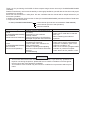
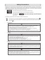

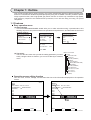
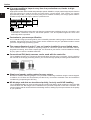
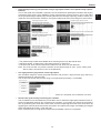
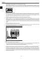
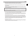
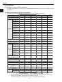
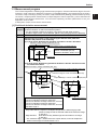
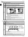
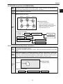
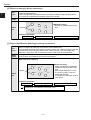
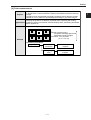

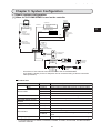
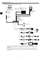
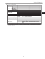

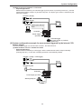
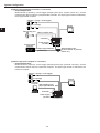
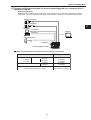
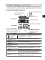


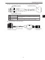
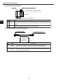
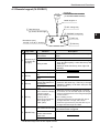

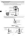
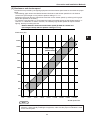
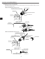
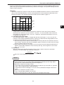

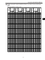

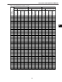

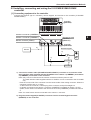
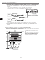

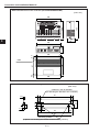
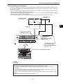

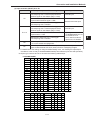
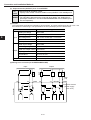
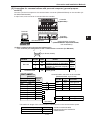
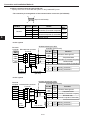

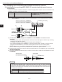
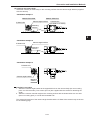

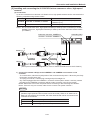
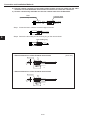
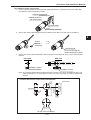
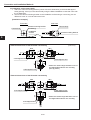
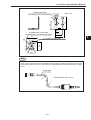
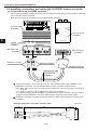
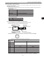
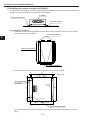

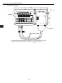
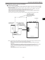
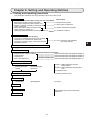

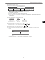
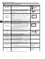
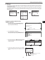
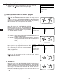
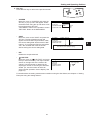
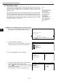
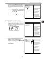
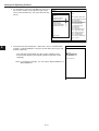
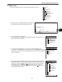
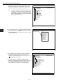
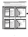

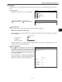
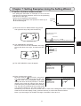
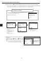
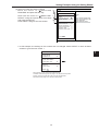
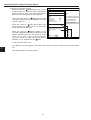

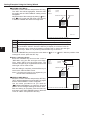


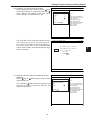
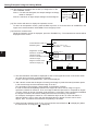
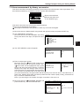
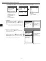

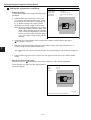
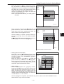

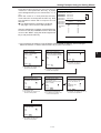
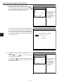
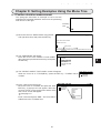
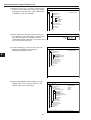

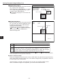
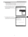
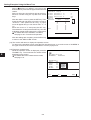
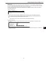


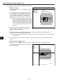


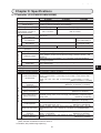
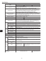
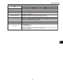
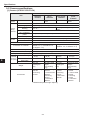

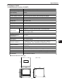


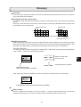
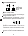
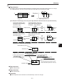
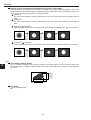
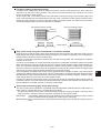

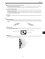

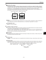
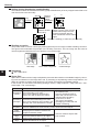
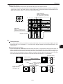
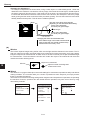
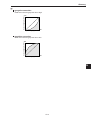
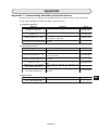

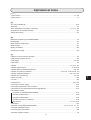
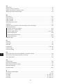


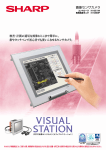
![68から79頁 [PDFファイル/652KB]](http://vs1.manualzilla.com/store/data/006650785_2-6af9625bbf4add5012e9c1ea9f77ca9e-150x150.png)