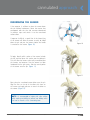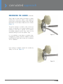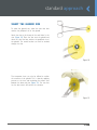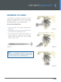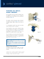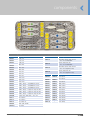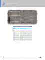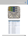
1
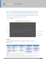
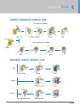
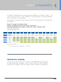
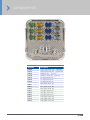
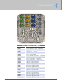
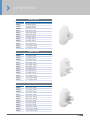
S H O U L D E R
Solutions by Tornier
A E Q UA L I S ™
P E R F O R M
S U R G I C A L T E C H N I Q U E
Aequalis PerFORM
G L E N O I D
S Y S T E M
surgical technique
T E C H N I Q U E
A E Q UA L I S ™
S U R G I C A L
P E R F O R M
S U R G I C A L T E C H N I Q U E
T O R N I E R
table of contents
A E Q U A L I S ™
P E R F O R M
G L E N O I D
S Y S T E M
IMPLANT RATIONALE
4
SURGICAL FLOW
5
INDICATIONS/CONTRAINDICATIONS6
SYSTEM COMPATIBILITY
7
COMMON TECHNIQUES FOR THE KEEL,
PEG & CORTILOC GLENOIDS
8
• Exposure
8
ARTICULAR CURVATURE OVERVIEW
9
DETERMINING ARTICULAR CURVATURE
CANNULATED APPROACH
• Optional : BLUEPRINT™ 3D Planning Software
• Confirming the Glenoid size
• Resurfacing the Glenoid
10
11-16 11
12
13-15
• Drilling the Central Hole
16
STANDARD APPROACH
17-20
• Select the Glenoid Size 17
• Drilling the Central Hole
18
• Resurfacing the Glenoid
19-20
IMPLANTATION OF THE KEELED GLENOID
21-24
• Preparing the Keel Slot
21-22
• Positioning the Keeled Glenoid Component
23-24
IMPLANTATION OF THE TORNIER PEGGED GLENOID
25-26
• Preparing the Peg Holes
25
• Positioning the Pegged Glenoid Component
26
IMPLANTATION OF THE CORTILOC™ PEGGED GLENOID
27-28
• Preparing the Peg Holes
27
• Positioning of the CortiLoc™ Glenoid Component
28
COMPONENTS29-35
• Common Tray - Upper Level
29
• Common Tray - Lower Level
30
• Keeled Tray
31
• Pegged Tray
32
• CortiLoc Tray
33
• Glenoids
34
• Miscellaneous
35
Aequalis™ PerFORM - Surgical Technique - UDTT144
3
implant rationale
“With current shoulder arthroplasty systems using a unique glenoid backside radius of curvature,
there is a risk to perform excessive reaming to “adapt the bone to the prosthesis” resulting in
sacrifice of the subchondral bone. Future implant design should consider including a range of
backside radius of curvatures adapted to the arthritic glenoid that may avoid excessive reaming
and bone sacrifice by “adapting the prosthesis to the bone.”
- DR. GILLES WALCH
Glenoid Articular Curvature Comparison
Arthritic Glenoids
Normal Mean
Normal 1 Std Dev
Conclusion
The average arthritic articular curvature is 39 mm with a range of 10 standard
deviation while the average normal articular curvature is 32 mm with a range of 3
standard deviation.
Study 1
Study 2
End Point
5 Year
10 Year
15 Year
Revision
99.8%
96.0%
77.5%
Radiological
99.0%
70.1%
25.8%
Revision
99.7%
98.3%
N/A
Radiological
99.7%
51.5%
N/A
Study 1: Pattern of Loosening of Polyethylene Keeled Glenoid in Primary OA (A Multi-Centered Study with >5 Year Follow-Up)
G. Walch; A. Young; P. Boileau; M. Loew; D. Gazielly; D. Molé
Study 2: “Results of a Convex-back Cemented Keeled Glenoid Component in Primary Osteoarthritis: Multicenter Study
with Follow-up Greater than 5 Years” G. Walch, A. Young, B. Melis, D. Gazielly, M. Loew, P. Boileau
Aequalis™ PerFORM - Surgical Technique - UDTT144
4
surgical flow
COMMON PREPARATION SURGICAL FLOW
Cannulated Technique
Place Pin
Position Reamer
Ream
Drill
Non-Cannulated Technique
Size
Drill
Ream
ANCHORAGE SPECIFIC SURGICAL FLOW
Keel
Drill Per.Pegs
Punch
Trial
Pegged
Drill Per.Pegs
Trial
CortiLoc™
Drill Enlarging Hole
Aequalis™ PerFORM - Surgical Technique - UDTT144
Drill Per.Pegs
5
Trial
indications & contraindications
AEQUALIS™ PerFORM GLENOID OVERVIEW
The Aequalis™ PerFORM glenoid system is a comprehensive offering that includes a variety of anchorage
options such as a Keeled, Standard Pegged and CortiLoc™ Pegged. These designs are based on extensive
anatomic studies* and are offered in 4 sizes. Additionally, both common and anchorage specific
instrumentation are included in the Aequalis PerFORM glenoid system.
The Tornier shoulder prostheses are intended for replacement of the shoulder joint to reduce pain and
improve shoulder mobility in comparison with preoperative status.
INDICATIONS
Prosthetic replacement with this device (Aequalis PerFORM glenoid component + humeral component)
may be indicated to relieve severe pain or significant disability caused by:
• Degenerative pathologies: osteoarthritis, rheumatoid polyarthritis, post-traumatic arthritis
• Primary and secondary necrosis of the humeral head
• Displaced 4-part upper humeral fracture
• Humeral head fracture
• Other pathologies where arthrodesis or resectional arthroplasty of the humeral head are not acceptable
• Revisions when other treatments or devices have failed
The Aequalis PerFORM glenoids are for use with cemented applications and are labeled as such.
CONTRAINDICATIONS
• Systemic infection
• Fever and/or local inflammation
• Rapid joint destruction or bone resorption apparent on roentgenograms
• Elevation of sedimentation rate unexplained by other disease, elevation of WBC count
• D
istant foci of infection from genitourinary, pulmonary, skin and other sites, dental focus infection that
may cause haematogenous spread to the implant site
• Use of this implant is contraindicated in the presence of significant injury to the upper brachial plexus
• Poor quality and/or insufficient quantity of glenoid bone stock (pre- or intraoperative glenoid fracture…)
• Nonfunctional deltoid or external rotator muscles
• Important and non-reparable rupture of the rotator cuff
• Neuromuscular disease (e.g. joint neuropathy)
• Known allergy to one of the materials
• Patient pregnancy
*Tornier internal data on file
Aequalis™ PerFORM - Surgical Technique - UDTT144
6
system compatibility
The Aequalis™ PerFORM glenoid has been designed to be compatible with the Simpliciti,™ Aequalis,™ and
Ascend™ humeral head systems in certain combinations. For more information on the cleared combinations
refer to the mismatch charts listed below.
(All models are not cleared in all countries; please contact your Tornier representative for information about
the availability.)
Aequalis™ Ascend Flex Shoulder System
Aequalis PerFORM Glenoids (Keeled, Pegged, and CortiLoc™)
with Aequalis/Simpliciti and Aequalis™ Ascend Flex Heads - Mismatch Chart
Combinations Heads/Glenoids
Diametrical Mismatch in mm
Size
Glenoid
Heads
37x13.5
39x14
41x15
43x16
46x17
48x18
50x16
50x19
52x19
52x23
54x23
54x27
Diameter
of curvature
39
41.2
43
45
48
50
55
52
54.6
52.4
54.7
54
Small
55.4
16.4
14.2
12.4
10.4
7.4
5.4
0.4
3.4
0.8
3
0.7
1.4
Medium
59.6
20.6
18.4
16.6
14.6
11.6
9.6
4.6
7.6
5
7.2
4.9
5.6
Large
63.6
24.6
22.4
20.6
18.6
15.6
13.6
8.6
11.6
9
11.2
8.9
9.6
XL
67.8
28.8
26.6
24.8
22.8
19.8
17.8
12.8
15.8
13.2
15.4
13.1
13.8
Cleared Mismatches
The cleared range for this combination is 1 to 24.8 mm
PREOPERATIVE PLANNING
A careful analysis of X-rays and axial CT scan views is recommended before surgery to evaluate
the following parameters: osteophytes, articular curvature, anterior and, more importantly,
posterior wear of the glenoid, as well as the location, orientation and depth of the glenoid vault.
Aequalis™ PerFORM - Surgical Technique - UDTT144
7
common techniques
COMMON OPERATIVE TECHNIQUES FOR THE
KEELED, PEGGED & CORTILOC™ GLENOIDS
Exposure
With the arm abducted and internally rotated, a posterior
glenoid retractor is placed on the posterior glenoid border
as the proximal humerus is dislocated posteriorly and
inferiorly. An angled retractor placed above the glenoid
and an angled Kolbel retractor placed in the subscapular
fossa are used to complete the exposure. (Figure 1)
If preoperatively the humerus rests in a fixed posteriorly
subluxed position, then the posterior capsule may be
stretched out sufficiently so that a posterior capsular
release for exposure may not be necessary.
Figure 1
If, after releasing the entire anterior capsule down to
6 o’clock on the glenoid face the shoulder is still tight,
then additional capsule is released around the posterior
inferior corner and up the posterior side until the humerus
can be adequately retracted for exposure (labrum and
posterior capsule). (Figure 1)
The glenoid retractor then is moved upward if more of
the posterior release needs to be completed. (Figure 2)
Figure 2
Aequalis™ PerFORM - Surgical Technique - UDTT144
8
surgical technique
ARTICULAR CURVATURE OVERVIEW
Recent studies have
than that of normal
articular curvature as
articular curvature is
demonstrated that the articular curvature of arthritic glenoids is much different
glenoids. In particular, one recent study reported the average arthritic glenoid
40 mm with a range of 11 standard deviations, while the average normal glenoid
32 mm with a range of 3 standard deviations. (Internal data on file)
The Aequalis™ PerFORM glenoid system is the first system to incorporate these new finding by
offering multiple backside curvatures of each size glenoid to preserve as much cortical bone as possible.
The chart below demonstrates the multiple backside curvatures for each of the four glenoid sizes.
Backside
Radius
Small
Medium
30
S 30
M 30
35
S 35
M 35
40
S 40
M 40
Large
Extra Large
L 40
XL 40
50
L 50
XL 50
60
L 60
XL 60
COLOR CODING
To improve operative efficiency, the Aequalis PerFORM instrumentation has been color coded by size.
Please refer to the chart below to see which colors are associated with which colors.
Small
Medium
Aequalis™ PerFORM - Surgical Technique - UDTT144
Large
X-Large
9
surgical technique
DETERMINING ARTICULAR
CURVATURE
Five radius gauges are provided to assist in determining
the general size and curvatures of the glenoid. Each
radius gauge is marked with the size (S-M / L-XL) and S/I
the radius (R30, R35, R40, R50, R60). (Figure 3)
The large end of the sizer is used to measure the best
fit of the glenoid superiorly/inferiorly, while the smaller
opposite end of the sizer is used to measure the best
fit of the glenoid anteriorly/posteriorly.
A/P
Figure 3
To determine the curvature of the glenoid, place a radius
gauge against the center of the glenoid.
Select the gauge that most precisely fits the native
glenoid. This radius will be a determining factor in which
instruments are used in subsequent steps. Evaluate the
fit of the radius gauge to the face of the glenoid
in multiple planes keeping the gauge centered in the
glenoid at all times. (Figure 4-5)
Ideal Fit
Figure 4
Poor Fit
Figure 5
Aequalis™ PerFORM - Surgical Technique - UDTT144
10
optional : BLUEPRINT™ 3D Planning Software
3 D P L A N N I N G
S O F T W A R E
If pre-operative planning is desired, the BLUEPRINT™ Planning Software may be used prior to the
procedure to visualize the anatomy in 3-dimensional space (automated 3D reconstruction) and perform a
virtual implantation of the Aequalis™ PerFORM glenoid. The software allows the surgeon to virtually
position the various implants and understand the optimal path of treatment based on the patient’s
anatomy. The software creates a visual aid when making important treatment decisions, including:
• Identification of glenoid wear patterns
• Visualization of humeral head subluxation & migration
• Planning correction of glenoid version
• Ensuring full implant seating
• Analyzing bone removal required for various implant options (reaming max)
• Assuring implant containment within the glenoid vault (size & radius curvature)
The BLUEPRINT™ Planning Software also provides information about the patient’s glenoid as well as the
virtual implant, including:
• Glenoid & Implant Version
• Glenoid & Implant Inclination
• Scapula Planes (Scapular plane, Transversal scapular plane and glenoid fossa plane)
• Glenoid bone removal measurements
• Implant seating coverage
For complete details on BLUEPRINTTM 3D Planning Software, please refer to the user manual and visit the website
www.tornierblueprint.com
Aequalis™ PerFORM - Surgical Technique - UDTT144
11
cannulated approach
CONFIRMING THE GLENOID SIZE
The glenoid size and curvature can be confirmed with
the sizer. This is done by applying pressure to the sizer
and evaluating the contact area between the bone and
sizer. The sizer that has the best match will determine
the size and the curvature. (Figure 6)
When using the cannulated approach, three pin guides
are available that can be attached to the sizer via
the rectangular shaped groove. This allows for easy
manipulation of the sizer on the face of the glenoid.
(Figure 7)
Additionally, the guides are cannulated in 0°, 5° and 10°
to allow for version correction based upon preoperative
planning. It is important to note that the pin guides can
place in either the anterior or posterior direction due to
the rectangular shape. This allows for the sizer to be
placed on the native surface or within the worn defect
of the glenoid when placing the guide pin.
Figure 6
0˚
5˚
10˚
Figure 7
With the appropriate sizer and pin guide assembled,
center the sizer on the glenoid and advance the guide
pin until bi-cortical fixation is achieved. Then slide the
assembly off the guide pin to prepare for reaming.
(Figure 8-9)
Figure 8
NOTE: If the cannulated pin bends or appears to be bent
in any step of the procedure, it must be removed and
replaced by a new pin.
Figure 9
Aequalis™ PerFORM - Surgical Technique - UDTT144
12
cannulated approach
RESURFACING THE GLENOID
If the exposure is sufficient to place the reamer down
the pin without interference, select the reamer that
corresponds with the size and curvature determined
in previous steps and attach it to the cannulated
reamer driver.
If exposure is difficult, a special slot in the internal ring
of the reamer will allow the reamer to easily be slided
down the pin and past the humerus before the handle
is attached to the reamer. (Figure 10)
Figure 10
To begin, identify which section of the reamer includes
the slot and then place this section over the guide pin.
This will allow the reamer to be easily maneuvered past
the humerus and retractors. Once the reamer has been
introduced into the joint space, slide the central portion
of the reamer onto the pin. (Figure 11)
Figure 11
Next, place the cannulated reamer driver over the pin.
Align the flats on the tip of the driver with those on
the reamer and apply pressure to attach the driver to
the reamer. (Figure 12)
NOTE: It is recommended to irrigate with saline solution
while reaming and drilling to prevent heat buildup which
can lead to necrosis of the surrounding bone.
Figure 12
Aequalis™ PerFORM - Surgical Technique - UDTT144
13
cannulated approach
RESURFACING THE GLENOID
(Continued)
Always begin by hand reaming and advance to power
reaming only if necessary. If power is used, engage the
reamer prior to contacting the glenoid surface and apply
light pressure. This will help to reduce the risk of fracture.
(Figure 13)
The goal of reaming is to obtain a bony surface that
matches the backside of the glenoid component while
removing as little bone as possible. The fit between
the glenoid component and the bony surface can be
evaluated utilizing the sizer from previous steps.
It is not advisable to ream down to cancellous bone.
Overaggressive reaming should be avoided to prevent
possible glenoid fracture and the future risk of component
shift or subsidence.
Figure 13
Once reaming is complete, remove the assembly by
sliding it off the pin. (Figure 14)
Figure 14
Aequalis™ PerFORM - Surgical Technique - UDTT144
14
cannulated approach
RESURFACING THE GLENOID
(Continued)
It is also possible to detach the reamer from the driver using the quick release handle. To do so, place the
tip of the quick release handle onto the shaft of the driver and slide it down until it sits on the reamer.
Apply downward pressure with the handle while pulling up on the driver to detach the reamer. (Figure 15)
Remove the individual parts in the reverse order that they were assembled.
NOTE: If the cannulated pin bends or appears to be
bent in any step of the procedure, it must be removed
and replaced by a new pin.
Figure 15
Aequalis™ PerFORM - Surgical Technique - UDTT144
15
cannulated approach
DRILLING THE CENTRAL HOLE
Two drill bit lengths are available, one for the S/M
and one for the L/XL size glenoid. To drill the central
hole, select the appropriate length (S/M or L/XL)
6 mm cannulated central drill bit and attach it to
the drill/reamer driver. Place the assembly over the pin
and drill until the collar of the bit is flush with the
glenoid. (Figure 16)
Figure 16
Remove the assembly over the guide pin and then
remove the guide pin before proceeding to the next
step. (Figure 17)
Figure 17
Aequalis™ PerFORM - Surgical Technique - UDTT144
16
standard approach
SELECT THE GLENOID SIZE
To select the glenoid size, select the sizer that best
matches the peripheral rim of the glenoid.
Attach the sizer to the clamp via the small holes in the
sizer (Figure 18). Place the sizer onto the glenoid and
select the sizer that best matches the peripheral rim of
the glenoid. The central location can then be marked
through the sizer.
Figure 18
The transparent sizers can also be utilized to confirm
the curvature of the glenoid. This is done by applying
pressure to the sizer and evaluating the contact area
between the bone and sizer (Figure 19). The sizer that
has the best match will confirm the curvature.
Figure 19
Aequalis™ PerFORM - Surgical Technique - UDTT144
17
standard approach
DRILLING THE CENTRAL HOLE
When using the standard approach, begin by attaching
the drill guide handle to the central hole drill guide.
Then select the appropriate length (S/M or L/XL) 6 mm
central hole drill bit and attach it to the drill/reamer
driver via the quick connect mechanism.
Figure 20
Once the instruments are assembled, align the guide
with central mark that was made when using the sizer
(Figure 20) and drill the central hole until the drill bit
collar bottoms out on the drill guide. (The drill bit is
provided with a laser etch line which represents the
depth to be drilled for those who prefer not to use the
drill guide.) (Figure 21)
Figure 21
Aequalis™ PerFORM - Surgical Technique - UDTT144
18
standard approach
RESURFACING THE GLENOID
If resurfacing of the glenoid is necessary, select the
reamer that corresponds with the size and curvature
determined in previous steps. Attach the reamer to either
the drill/reamer driver or the articulated driver.
Using the Articulated Driver
1.
Attach the reamer in the pivoted unlocked position.
(Figure 22)
Figure 23
2.Once attached, insert the tip of the reamer into the
central hole of the glenoid. (Figure 23)
3.Once the reamer tip is seated, use the handle as a
lever and retract the reamer shaft into the straight
position. Slide the outer sleeve into the locked
position. (Figure 24-25)
Figure 24
Figure 22
NOTE: It is recommended to irrigate with saline solution
while reaming and drilling to prevent heat buildup which
can lead to necrosis of the surrounding bone.
Figure 25
Aequalis™ PerFORM - Surgical Technique - UDTT144
19
standard approach
Always begin by hand reaming and advance to power
reaming only if necessary. If power is used, engage
the reamer prior to contacting the glenoid surface and
apply light pressure. This will help to reduce the risk
of fracture.
The goal of reaming is to obtain a bony surface that
matches the backside of the glenoid component while
removing as little bone as possible. The fit between
the glenoid component and the bony surface can be
evaluated utilizing the sizer from previous steps.
It is not advisable to ream down to cancellous bone.
Overaggressive reaming should be avoided to prevent
possible glenoid fracture and the future risk of component
shift on subsidence.
CAUTION: The articulated driver can only be used in the
straight locked position.
NOTE: It may be helpful to remove any posterior retractors
prior to inserting the articulated driver. The handle will
then in essence become the retractor.
Aequalis™ PerFORM - Surgical Technique - UDTT144
20
keeled glenoid
IMPLANTATION OF THE AEQUALIS
PERFORM KEELED GLENOID
Preparing the Keel Slot
To prepare the keel slot, begin by selecting the appropriate
size (S/M or L/XL) keeled peripheral drill guide.
Attach the drill guide to the drill guide handle and insert
the post on the backside of the guide into the central hole.
(Figure 26)
Align the superior and inferior holes with the supero-inferior
axis of the native glenoid. (Figure 26)
Figure 26
With the drill guide in place, select a drill bit, either the 5 mm
drill bit for the S/M size or the 6 mm drill bit for the L/XL and
attach the bit to the drill/reamer driver. Drill the superior hole
until the collar of the drill bit contacts the guide. (Figure 27)
Figure 27
Using the stabilization peg clamp, place the appropriate
size stabilization peg into the superior hole and then
drill the inferior hole. (Figure 28)
Figure 28
Aequalis™ PerFORM - Surgical Technique - UDTT144
21
keeled glenoid
The stabilization peg can then be removed along with the
guide. (Figure 28-29)
The bony bridges between the three holes are broken with
a rongeur or small osteotome.
Figure 29
Then select the appropriate sized keel punch (S-M
or L-XL) which is used to compact the cancellous bone
(Figure 30-31). The shape of the keel is then prepared
by compacting the cancellous bone using the selected keel
punch. Compaction of the cancellous bone is a preferred
technique to improve glenoid component fixation.
Figure 30
Figure 31
Aequalis™ PerFORM - Surgical Technique - UDTT144
22
keeled glenoid
POSITIONING THE KEELED GLENOID COMPONENT
Once the keel slot has been fully prepared, select the
appropriate size trial glenoid. The trial is inserted into the
keel slot using the trial grasper and can be seated with
the impactor. (Figure 32)
Figure 32
Two windows, anterior and posterior, allow visualization of the
bone to trial interface. If the trial has acceptable backside
support, remove the trial with the grasper. (Figure 33)
Figure 33
Aequalis™ PerFORM - Surgical Technique - UDTT144
23
keeled glenoid
It is recommended to carefully clean and dry the glenoid
surface and keel slot prior to cementing.
Once the glenoid is clean and dry, introduce the bone
cement and impact the final implant (Figure 34-36).
It is recommended to maintain pressure on the face of
the glenoid with the impactor while the cement hardens.
It is not recommended to cement the back face of the
glenoid. The cement mantle, at the face, should be less
than 1 mm.*
Figure 34
NOTE: The keel should not be altered in any manner prior
to implantation.
NOTE: Once a specific anchorage size (S/M or L/XL) has
been prepared, it is not advisable to upsize or downsize
the implant.
Figure 35
Figure 36
*Long-term results of cancellous compaction technique for glenoid
replacement in total shoulder arthroplasty for primary osteoarthritis.
O. Verborgt, G. Walch, V. Belloti, and D. Gazielly.
Aequalis™ PerFORM - Surgical Technique - UDTT144
24
pegged glenoid
IMPLANTATION OF THE AEQUALIS
PERFORM PEGGED GLENOID
Preparing the Peg Holes
To prepare the peripheral holes, begin by selecting the S/M
or L/XL pegged peripheral drill guide.
Attach the drill guide to the drill guide handle and insert
the post on the backside of the guide into the central hole.
(Figure 37)
Figure 37
Align the drill guide on the glenoid. With the drill guide
in place, attach the peripheral drill bit to the drill/reamer
driver. Drill the superior hole until the collar of the drill bit
contacts the guide. (Figure 38)
Figure 38
Using the stabilization peg clamp, place the stabilization
peg into the superior hole and then drill the anterior hole
(Figure 39-40). A second stabilization peg can be inserted
for addition stability and the posterior hole is then drilled.
(Figure 40)
Figure 39
The stabilization pegs can then be removed along
with the guide.
Figure 40
Aequalis™ PerFORM - Surgical Technique - UDTT144
25
pegged glenoid
POSITIONING THE PEGGED
GLENOID COMPONENT
Once the peripheral holes have been fully prepared, select
the appropriate size trial glenoid. The trial is inserted into
the glenoid using the trial grasper and can be seated
with the impactor. (Figure 41)
Figure 41
Two windows, anterior and posterior, allow visualization
of the bone to trial interface (Figure 42). If the trial has
acceptable backside support, remove the trial with the
grasper.
Figure 42
It is recommended to carefully clean and dry the glenoid
surface and peg holes prior to cementing.
Once the glenoid is clean and dry, introduce the bone
cement and impact the final implant. It is not recommended
to cement the back face of the glenoid. (Figure 43-44) It
is recommended to maintain pressure on the face of the
glenoid with the impactor while the cement hardens.*
Figure 43
NOTE: The pegs should not be altered in any manner
prior to implantation.
NOTE: Once a specific anchorage size (S/M or L/XL) has
been prepared, it is not advisable to upsize or downsize
the implant.
*Long-term results of cancellous compaction technique for glenoid
replacement in total shoulder arthroplasty for primary osteoarthritis.
O. Verborgt, G. Walch, V. Belloti, and D. Gazielly.
Figure 44
Aequalis™ PerFORM - Surgical Technique - UDTT144
26
cortiloc™ glenoid
IMPLANTATION OF THE AEQUALIS
PERFORM CORTILOC™ GLENOID
Preparing the Peg Holes
If not completed in a previous step, the central hole should
be enlarged at this time.
To enlarge the hole, attach the appropriate length (S/M or
L/XL) 8.4 mm CortiLoc drill bit to the drill/reamer driver.
Then assemble the CortiLoc central drill guide to the drill
guide handle.
Place the drill guide on the reamed glenoid. Drill until the
collar of the bit contacts the guide. (Figure 45) (The drill
bit is provided with a laser etch line which represents the
depth to be drilled for those who prefer not to use the
drill guide.)
Figure 45
Once completed, remove the drill guide and prepare the
peripheral holes.
To prepare the peripheral holes, begin by selecting one of
the S/M or L/XL CortiLoc drill guides.
Attach the drill guide to the drill guide handle and insert
the tip post on the backside of the guide into the central
hole.
Figure 46
Align the drill guide on the glenoid. With the drill guide
in place, attach the peripheral drill bit to the drill/reamer
driver. Drill the superior hole until the collar of the drill
bit contacts the guide. (Figure 46)
Using the stabilization peg clamp, place the stabilization
peg into the superior hole and then drill the anterior hole.
(Figure 47) A second stabilization peg can be inserted for
additional stability and the posterior hole is then drilled.
The stabilization pegs can then be removed along
with the guide.
Figure 47
Aequalis™ PerFORM - Surgical Technique - UDTT144
27
cortiloc™ glenoid
POSITIONING THE CORTILOC™
GLENOID COMPONENT
Once the peripheral holes have been fully prepared, select
the appropriate size trial glenoid. The trial is inserted into
the glenoid using the trial grasper and can be seated with
the impactor. (Figure 48)
Two windows, anterior and posterior, allow visualization
of the bone to trial interface. (Figure 49) If the trial has
acceptable backside support, remove the trial with the
grasper.
Figure 48
It is recommended to carefully clean and dry the glenoid
surface and peg holes prior to cementing.
Once the glenoid is clean and dry, introduce the bone
cement and impact the final implant. It is not recommended
to cement the back of the glenoid. (Figure 50) It is
recommended to maintain pressure on the face of the
glenoid with the impactor while the cement hardens.*
Figure 49
The final implant can then be inserted with the trial
grasper and seated using the impactor. It is recommended
to maintain pressure on the face of the glenoid with the
impactor while the cement hardens.
NOTE: The pegs should not be altered in any manner
prior to implantation.
NOTE: Once a specific anchorage size (S/M or L/XL) has
been prepared, it is not advisable to upsize or downsize
the implant.
Reduction Testing and Closure
The reduction of the joint, testing of mobility and stability
and closure is described in detail in the humeral surgical
technique.
*Long-term results of cancellous compaction technique for glenoid
replacement in total shoulder arthroplasty for primary osteoarthritis.
O. Verborgt, G. Walch, V. Belloti, and D. Gazielly.
Aequalis™ PerFORM - Surgical Technique - UDTT144
28
Figure 50
components
Common Tray - Upper Level (Ref. YKAD210)
Reference
Description
MWE011
MWE012
MWE013
MWE014
MWE015
MWE016
MWE017
MWE018
MWE019
MWE020
MWE021
MWE022
MWE031
MWE032
MWE033
MWE034
MWE035
MWE036
MWE040
MWE111
MWE112
MWE113
MWE042
MWB253
S30 Sizer
S35 Sizer
S40 Sizer
M30 Sizer
M35 Sizer
M40 Sizer
L40 Sizer
L50 Sizer
L60 Sizer
XL40 Sizer
XL50 Sizer
XL60 Sizer
Radius Gauge – Small/Medium 30 mm
Radius Gauge – Small/Medium 35 mm
Radius Gauge – Small/Medium 40 mm
Radius Gauge – Large/Extra Large 40 mm
Radius Gauge – Large/Extra Large 50 mm
Radius Gauge – Large/Extra Large 60 mm
Central Hole Drill Guide – Ø 6 mm
Pin Guide 0°
Pin Guide 5°
Pin Guide 10°
Drill Guide Handle
Pin Driver
Aequalis™ PerFORM - Surgical Technique - UDTT144
YKAD210A (Circular Reamer)
YKAD210B (Crescent Reamer)
Reference
Description
MWE153
Cannulated Central Hole Drill Bit
– Ø 6 mm Small/Medium
Central Holed Drill Bit
– Ø 6 mm Small/Medium
Cannulated Central Hole Drill Bit
– Ø 6 mm Large/Extra Large
MWE154
MWE155
Central Holed Drill Bit
– Ø 6 mm Large/Extra Large
MWE156
Circular
Crescent
MWE160
MWE161
MWE162
MWE163
MWE164
MWE165
MWE166
MWE167
MWE168
MWE169
MWE170
MWE171
MWE110
MWE260
MWE261
MWE262
MWE263
MWE264
MWE265
MWE266
MWE267
MWE268
MWE269
MWE270
MWE271
--
29
S30 Reamer
S35 Reamer
S40 Reamer
M30 Reamer
M35 Reamer
M40 Reamer
L40 Reamer
L50 Reamer
L60 Reamer
XL40 Reamer
XL50 Reamer
XL60 Reamer
Sizer Clamp
components
Common Tray - Lower Level (Ref. YKAD210)
Reference
Description
MWE044
MWE046
MWD552
MWE150
MWE151
MWE152
MWE080 or MWE180*
MWB236
MWE114
MWA652
MWE157
Stabilization Peg Remover
Glenoid Impactor
12 mm Wrench
Articulated Driver
Cannulated Reamer Driver
Cannulated Drill/Reamer Driver w/Tip
T-Handle – SZH
Cleaning Rod
Glenoid Grasper
Trial Grasper
Alignment Pin
MWE158
Quick Release Handle
* Available upon request
Aequalis™ PerFORM - Surgical Technique - UDTT144
30
components
Keeled Tray (Ref. YKAD213)
Reference
Description
MWE095
MWE096
MWE097
MWE098
MWE199
MWE201
MWE101
MWE102
MWE501
MWE502
MWE503
MWE511
MWE512
MWE513
MWE521
MWE522
MWE523
MWE531
MWE532
MWE533
Keeled Peripheral Drill Guide - Small/Medium
Keeled Peripheral Drill Guide - Large/Extra Large
Stabilization Peg - Ø 5 mm
Stabilization Peg - Ø 6 mm
Peripheral Drill Bit - Ø 5 mm
Peripheral Drill Bit - Ø 6 mm
Keeled Punch - Small/Medium
Keeled Punch - Large/Extra Large
S30 Keeled Glenoid Trial
S35 Keeled Glenoid Trial
S40 Keeled Glenoid Trial
M30 Keeled Glenoid Trial
M35 Keeled Glenoid Trial
M40 Keeled Glenoid Trial
L40 Keeled Glenoid Trial
L50 Keeled Glenoid Trial
L60 Keeled Glenoid Trial
XL40 Keeled Glenoid Trial
XL50 Keeled Glenoid Trial
XL60 Keeled Glenoid Trial
Aequalis™ PerFORM - Surgical Technique - UDTT144
31
components
Pegged Tray (Ref. YKAD212)
Reference
Description
MWE090
MWE091
MWE083
MWE200
MWE301
MWE302
MWE303
MWE311
MWE312
MWE313
MWE321
MWE322
MWE323
MWE331
MWE332
MWE333
Pegged Peripheral Drill Guide - Small/Medium
Pegged Peripheral Drill Guide - Large/Extra Large
Stabilization Peg - Ø 5.4 mm
Peripheral Drill Bit Dia - Ø 5.4 mm
S30 Pegged Glenoid Trial
S35 Pegged Glenoid Trial
S40 Pegged Glenoid Trial
M30 Pegged Glenoid Trial
M35 Pegged Glenoid Trial
M40 Pegged Glenoid Trial
L40 Pegged Glenoid Trial
L50 Pegged Glenoid Trial
L60 Pegged Glenoid Trial
XL40 Pegged Glenoid Trial
XL50 Pegged Glenoid Trial
XL60 Pegged Glenoid Trial
Aequalis™ PerFORM - Surgical Technique - UDTT144
32
components
CortiLoc™ Pegged Tray (Ref. YKAD211)
Reference
Description
MWE081
MWE082
MWE083
MWE200
MWE085
CortiLoc Peripheral Drill Guide - Small/Medium
CortiLoc Peripheral Drill Guide - Large/Extra Large
Stabilization Peg - Ø 5.4 mm
Peripheral Drill Bit Dia - Ø 5.4 mm
CortiLoc Central Drill Guide
CortiLoc Cannulated Central Drill Bit - Small/Medium
CortiLoc Cannulated Central Drill Bit - Large/Extra Large
CortiLoc Central Drill Bit - Small/Medium
CortiLoc Central Drill Bit - Large/Extra Large
S30 CortiLoc Pegged Glenoid Trial
S35 CortiLoc Pegged Glenoid Trial
S40 CortiLoc Pegged Glenoid Trial
M30 CortiLoc Pegged Glenoid Trial
M35 CortiLoc Pegged Glenoid Trial
M40 CortiLoc Pegged Glenoid Trial
L40 CortiLoc Pegged Glenoid Trial
L50 CortiLoc Pegged Glenoid Trial
L60 CortiLoc Pegged Glenoid Trial
XL40 CortiLoc Pegged Glenoid Trial
XL50 CortiLoc Pegged Glenoid Trial
XL60 CortiLoc Pegged Glenoid Trial
MWE202
MWE203
MWE204
MWE205
MWE401
MWE402
MWE403
MWE411
MWE412
MWE413
MWE421
MWE422
MWE423
MWE431
MWE432
MWE433
Aequalis™ PerFORM - Surgical Technique - UDTT144
33
components
Keeled Glenoid
Reference
Description
DWE501
DWE502
DWE503
S30 Keeled Glenoid
S35 Keeled Glenoid
S40 Keeled Glenoid
DWE511
DWE512
DWE513
M30 Keeled Glenoid
M35 Keeled Glenoid
M40 Keeled Glenoid
DWE521
DWE522
DWE523
L40 Keeled Glenoid
L50 Keeled Glenoid
L60 Keeled Glenoid
DWE531
DWE532
DWE533
XL40 Keeled Glenoid
XL 50 Keeled Glenoid
XL 60 Keeled Glenoid
Pegged Glenoid
Reference
Description
DWE301
DWE302
DWE303
S30 Pegged Glenoid
S35 Pegged Glenoid
S40 Pegged Glenoid
DWE311
DWE312
DWE313
M30 Pegged Glenoid
M35 Pegged Glenoid
M40 Pegged Glenoid
DWE321
DWE322
DWE323
L40 Pegged Glenoid
L50 Pegged Glenoid
L60 Pegged Glenoid
DWE331
DWE332
DWE333
XL40 Pegged Glenoid
XL 50 Pegged Glenoid
XL 60 Pegged Glenoid
CortiLoc™ Pegged Glenoid
Reference
Description
DWE401
DWE402
DWE403
S30 CortiLoc Glenoid
S35 CortiLoc Glenoid
S40 CortiLoc Glenoid
DWE411
DWE412
DWE413
M30 CortiLoc Glenoid
M35 CortiLoc Glenoid
M40 CortiLoc Glenoid
DWE421
DWE422
DWE423
DWE431
DWE432
DWE433
L40 CortiLoc Glenoid
L50 CortiLoc Glenoid
L60 CortiLoc Glenoid
XL40 CortiLoc Glenoid
XL 50 CortiLoc Glenoid
XL 60 CortiLoc Glenoid
Aequalis™ PerFORM - Surgical Technique - UDTT144
34
components
Miscellaneous Order Information
Reference
Description
DWD014
DWD013
DWD015
DWD011
DWD012
DWD013
MWE157 (1)
DWD063 (2)
MWB319 (2)
DWD168 (1)
Pressurization Kit Peg Glenoid
Cement Scraper
Peg Nozzle
Pressurization Kit Keeled Glenoid
Keel Nozzle
Cement Scraper
Non-Sterile Pin – Ø 2.5 X 200 mm
Sterile Single Use Pin – Ø 2.5 X 200 mm
Non-Sterile Pin – Ø 2.5 X 200 mm
Aequalis™ PerFORM - Surgical Technique - UDTT144
Sterile Single Use Pin – Ø 2.5 X 200 mm
35
notes
Aequalis™ PerFORM - Surgical Technique - UDTT144
36
notes
Aequalis™ PerFORM - Surgical Technique - UDTT144
37
notes
Aequalis™ PerFORM - Surgical Technique - UDTT144
38
notes
Aequalis™ PerFORM - Surgical Technique - UDTT144
39
U S H E A D Q UA R T E R S
I N T E R N AT I O N A L H E A D Q UA R T E R S
M A N U FA C T U R E R
Tornier, Inc.
10801 Nesbitt Avenue South
Bloomington, MN 55437
USA
+ 1 952 426 7600
Tornier SAS
161 rue Lavoisier
38330 Montbonnot Saint Martin
France
+ 33 (0)4 76 61 35 00
www.tornier.com
Manufacturer BLUEPRINT™ 3D Planning Software: IMASCAP SAS, 65 Place Copernic, 29280 PLOUZANE, FRANCE
Distributor BLUEPRINT™ 3D Planning Software: Tornier SAS, FRANCE
Prior to using any Tornier device, please review the instructions for use and surgical technique for a complete listing of
indications, contraindications, warnings, precautions, potential adverse events, and directions for use.
Aequalis™ PerFORM - Surgical Technique - UDTT144