1
Configuring HP-UX For Peripherals
HP 9000 Computers
Manufacturing Part Number: B2355-90698
November 2000
© Copyright 2000 Hewlett-Packard Company
1
Notices
Use of this document and flexible disc(s) or tape cartridge(s) supplied for
this pack is restricted to this product only. Additional copies of the
programs can be made for security and back-up purposes only. Resale of
the programs in their present form or with alterations, is expressly
prohibited.
This document contains information which is protected by copyright. All
rights are reserved. Reproduction, adaptation, or translation without
prior written permission is prohibited, except as allowed under the
copyright laws.
Hewlett-Packard Co.
3000 Hanover St.
Palo Alto, CA 94304
The information contained in this document is subject to change without
notice.
Hewlett-Packard makes no warranty of any kind with regard to this
document, including, but not limited to, the implied warranties of
merchantability and fitness for a particular purpose. Hewlett-Packard
shall not be liable for errors contained herein or direct, indirect, special,
incidental or consequential damages in connection with the furnishing,
performance, or use of this material.
A copy of the specific warranty terms applicable to your Hewlett-Packard
product and replacement parts can be obtained from your local Sales and
Service Office.
UNIX is a registered trademark in the United States and other
countries, licensed exclusively through X/Open Company Limited.
X Window System is a trademark of the Massachusetts Institute of
Technology.
MS-DOS and Microsoft are U.S. registered trademarks of Microsoft
Corporation.
OSF/Motif is a trademark of the Open Software Foundation, Inc. in the
U.S. and other countries.
Copyright ) The Regents of the University of California 1979, 1980, 1983,
1987, 1993
2
This software and documentation is based in part on the Fourth Berkeley
Software Distribution under license from the Regents of the University
of California.
Copyright ) The Regents of the University of Colorado, a body corporate
1979
This document has been reproduced and modified with the permission of
the Regents of the University of Colorado, a body corporate.
Copyright ) 1980, 1984, 1986 Novell, Inc.
Copyright ) 1986-1992 Sun Microsystems, Inc.
Copyright ) 1985-86, 1988 Massachusetts Institute of Technology.
Copyright ) 1989-93 The Open Software Foundation, Inc.
Copyright ) 1986 Digital Equipment Corporation.
Copyright ) 1990 Motorola, Inc.
Copyright ) 1990, 1991, 1992 Cornell University
Copyright ) 1989-1991 The University of Maryland.
Copyright ) 1988 Carnegie Mellon University.
Restricted Rights Legend. Use, duplication, or disclosure by the U.S.
Government Department is subject to restrictions as set forth in
subparagraph (c) (1) (ii) of the Rights in Technical Data and Computer
Software clause at DFARS 252.227-7013 for DOD agencies, and
subparagraphs (c) (1) and (c) (2) of the Commercial Computer Software
Restricted Rights clause at FAR 52.227-19 for other agencies.
3
4
Contents
1. Getting Started
Peripheral Configuration in its Simplest Terms . . . . . . . . . . . . . . . . . . .17
Using SAM to Configure Peripherals . . . . . . . . . . . . . . . . . . . . . . . . . .18
Using HP-UX Commands to Configure Peripherals. . . . . . . . . . . . . . .18
Understanding I/O Convergence. . . . . . . . . . . . . . . . . . . . . . . . . . . . . . . .20
Understanding Loadable Device Drivers . . . . . . . . . . . . . . . . . . . . . . . . .21
DLKM Module Types . . . . . . . . . . . . . . . . . . . . . . . . . . . . . . . . . . . . . . .21
New Module Packaging . . . . . . . . . . . . . . . . . . . . . . . . . . . . . . . . . . . . .21
Advantages of DLKM Drivers . . . . . . . . . . . . . . . . . . . . . . . . . . . . . . . .22
Understanding Device Special File Names . . . . . . . . . . . . . . . . . . . . . . .23
Sample Device Special File Names . . . . . . . . . . . . . . . . . . . . . . . . . . . .24
Decoding Device Special Files with lssf . . . . . . . . . . . . . . . . . . . . . . . .25
Viewing the System Configuration with ioscan . . . . . . . . . . . . . . . . . . . .26
Terse Listing of ioscan . . . . . . . . . . . . . . . . . . . . . . . . . . . . . . . . . . . . . .26
Full Listing of ioscan . . . . . . . . . . . . . . . . . . . . . . . . . . . . . . . . . . . . . . .28
Configuring HP-UX for any Peripheral (A Summary). . . . . . . . . . . . . . .31
2. Managing PCI Cards with OLAR
How is the information in this chapter structured? . . . . . . . . . . . . . . . .34
PCI Card OLAR Overview and Concepts . . . . . . . . . . . . . . . . . . . . . . . . .35
Introduction . . . . . . . . . . . . . . . . . . . . . . . . . . . . . . . . . . . . . . . . . . . . . .35
Important Terms and Concepts . . . . . . . . . . . . . . . . . . . . . . . . . . . . . . .35
Planning and Preparation . . . . . . . . . . . . . . . . . . . . . . . . . . . . . . . . . . .36
OLAR Scripts . . . . . . . . . . . . . . . . . . . . . . . . . . . . . . . . . . . . . . . . . . . . .40
IMPORTANT ADVANCED CONSIDERATIONS . . . . . . . . . . . . . . . .41
How to On-line Replace (OLR) a PCI Card using SAM. . . . . . . . . . . . . .43
How to On-line Add (OLA) a PCI Card using SAM . . . . . . . . . . . . . . . . .46
Performing OLAR procedures from the command line . . . . . . . . . . . . . .48
5
Contents
Analyzing Critical Resources . . . . . . . . . . . . . . . . . . . . . . . . . . . . . . . .
OLAR Scripts. . . . . . . . . . . . . . . . . . . . . . . . . . . . . . . . . . . . . . . . . . . . .
Dynamically Loadable Kernel Modules (DLKM) . . . . . . . . . . . . . . . .
How to On-Line Replace (OLR) a PCI card using rad . . . . . . . . . . . .
How to On-Line Add (OLA) a PCI Card using rad . . . . . . . . . . . . . . .
48
49
53
54
60
3. Configuring Interface Cards
Planning to Configure an Interface Card . . . . . . . . . . . . . . . . . . . . . . . . 66
Maximum Configurations. . . . . . . . . . . . . . . . . . . . . . . . . . . . . . . . . . . 67
Selecting Device Drivers for Your Interface Cards. . . . . . . . . . . . . . . . .
Asynchronous Data Communication Configuration Guidelines. . . . .
Centronics (Parallel) Configuration Guidelines . . . . . . . . . . . . . . . . .
EISA Configuration Guidelines . . . . . . . . . . . . . . . . . . . . . . . . . . . . . .
Graphics Card Configuration Guidelines . . . . . . . . . . . . . . . . . . . . . .
Maintaining the Accuracy of Customized Graphics . . . . . . . . . . . . . .
Networking Configuration Guidelines . . . . . . . . . . . . . . . . . . . . . . . . .
SCSI Configuration Guidelines . . . . . . . . . . . . . . . . . . . . . . . . . . . . . .
69
69
76
76
77
80
80
89
Configuring an Interface Card. . . . . . . . . . . . . . . . . . . . . . . . . . . . . . . . . 96
For Further Information on Interface Cards . . . . . . . . . . . . . . . . . . . . . 99
4. Configuring Terminals and Modems
Planning to Configure a Terminal or Modem . . . . . . . . . . . . . . . . . . . .
Planning to Configure a Port for a Terminal . . . . . . . . . . . . . . . . . . .
Planning to Configure a non-HP Terminal . . . . . . . . . . . . . . . . . . . .
Planning to Configure a Port for a Modem . . . . . . . . . . . . . . . . . . . .
102
102
102
103
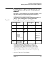
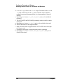
Selecting Device Drivers for Terminals and Modems . . . . . . . . . . . . . 105
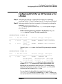
Configuring HP-UX for an HP Terminal or for a Modem . . . . . . . . . . 107
Additionally Configuring HP-UX for a Terminal . . . . . . . . . . . . . . . . . 111
Differences between Console and Terminal Configuration . . . . . . . 112
6
Contents
Running Screen-Oriented Applications on a Terminal . . . . . . . . . . .113
Configuring a Non-HP Terminal as a Console . . . . . . . . . . . . . . . . . .113
Additionally Configuring HP-UX for a Modem . . . . . . . . . . . . . . . . . . .123
Requirements for Modems to Work on HP-UX . . . . . . . . . . . . . . . . . .126
Removing or Moving a Terminal or Modem . . . . . . . . . . . . . . . . . . . . . .128
Troubleshooting Terminal Problems . . . . . . . . . . . . . . . . . . . . . . . . . . .129
Unresponsive Terminals . . . . . . . . . . . . . . . . . . . . . . . . . . . . . . . . . . .129
Garbage Displayed on the Terminal Screen . . . . . . . . . . . . . . . . . . . .132
For Further Information on Terminals and Modems . . . . . . . . . . . . . .135
5. Configuring Disk Drives, Disk Arrays, and CD-ROM Drives
Planning to Configure a Disk Drive . . . . . . . . . . . . . . . . . . . . . . . . . . . .138
Performance . . . . . . . . . . . . . . . . . . . . . . . . . . . . . . . . . . . . . . . . . . . . .138
Considerations for Configuring a Disk Array . . . . . . . . . . . . . . . . . . .138
Considerations for Configuring a CD-ROM Drive . . . . . . . . . . . . . . .139
Considerations for Configuring a Floppy Disk Drive . . . . . . . . . . . . .139
Selecting Device Drivers for a Disk Device and Interface. . . . . . . . . . .141
SCSI Disk Configuration Guidelines. . . . . . . . . . . . . . . . . . . . . . . . . .141
Floppy Disk Drive Configuration Guidelines . . . . . . . . . . . . . . . . . . .143
Configuring HP-UX for a New Disk Device . . . . . . . . . . . . . . . . . . . . . .145
Planning to Configure into your System a Disk Already . . . . . . . . . . .148
Ensuring Against Clashes with HP-UX 10.0 . . . . . . . . . . . . . . . . . . .148
Understanding How to Configure a Disk Already . . . . . . . . . . . . . . .149
Configuring into your System an Unpartitioned Disk Already . . . . . .151
Configuring into Your System a Partitioned Disk Already . . . . . . . . . .153
Configuring into your System an LVM Disk Already . . . . . . . . . . . . . .156
Moving a Disk Drive to a Different Address . . . . . . . . . . . . . . . . . . . . .159
7
Contents
Removing a Disk Drive . . . . . . . . . . . . . . . . . . . . . . . . . . . . . . . . . . . . . 166
Finding Out the Disk Model Number and Other Information . . . . . . 169
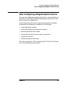
After Configuring HP-UX for the Disk Device . . . . . . . . . . . . . . . . . . . 170
6. Configuring Magneto-Optical Devices
Planning to Configure a Magneto-Optical Device . . . . . . . . . . . . . . . . 172
Characteristics of Magneto-Optical Devices . . . . . . . . . . . . . . . . . . . 172
Understanding Magneto-Optical Media Capacity . . . . . . . . . . . . . . 173
Magneto-Optical Disk Configuration Guidelines . . . . . . . . . . . . . . . . . 174
Configuring HP-UX for a Magneto-Optical Disk. . . . . . . . . . . . . . . . 175
Magneto-Optical Disk Library Configuration Guidelines . . . . . . . . . . 176
Configuring HP-UX for a Magneto-Optical Disk Library . . . . . . . . . 177
After Configuring a Magneto-Optical Device . . . . . . . . . . . . . . . . . . . . 181
7. Configuring Tape Drives
Selecting Device Drivers for a Tape Device and Interface . . . . . . . . . . 184
SCSI Tape Drive Configuration Guidelines. . . . . . . . . . . . . . . . . . . . 184
Configuring HP-UX for a Tape Drive . . . . . . . . . . . . . . . . . . . . . . . . . . 187
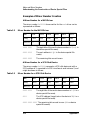
Creating Customized Device Special Files for Tape Devices . . . . . . . . 190
Examples . . . . . . . . . . . . . . . . . . . . . . . . . . . . . . . . . . . . . . . . . . . . . . . 190
After Configuring a Tape Drive . . . . . . . . . . . . . . . . . . . . . . . . . . . . . . . 192
8. Configuring Printers and Plotters
Preparing to Configure HP-UX for a Printer or Plotter . . . . . . . . . . . .
Choosing Means of Access . . . . . . . . . . . . . . . . . . . . . . . . . . . . . . . . .
Hardware Concerns . . . . . . . . . . . . . . . . . . . . . . . . . . . . . . . . . . . . . .
Software Concerns . . . . . . . . . . . . . . . . . . . . . . . . . . . . . . . . . . . . . . .
8
196
196
197
198
Contents
Selecting Device Drivers for Your Printer or Plotter . . . . . . . . . . . . . . .199
Guidelines for Configuring a Printer or Plotter to a Serial . . . . . . . .199
Guidelines for Configuring a Printer or Plotter to a Parallel . . . . . .203
Guidelines for Configuring a Printer to a SCSI Interface . . . . . . . . .205
Configuring a Printer Using HP-UX Commands. . . . . . . . . . . . . . . . . .206
Creating a Device Special File for a Printer or Plotter . . . . . . . . . . .209
Guidelines for Configuring a Non-HP Printer to a Parallel Port. . . .211
Configuring a Plotter or other Non-Automatically Configurable . . . . .213
Moving a Printer or Plotter. . . . . . . . . . . . . . . . . . . . . . . . . . . . . . . . . . .216
For Further Information on Printer-Related Tasks. . . . . . . . . . . . . . . .217
For Further Information on Plotter-Related Tasks . . . . . . . . . . . . . . . .219
9. Configuring Uninterruptable Power Systems
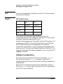
Planning to Configure a UPS . . . . . . . . . . . . . . . . . . . . . . . . . . . . . . . . .222
Hardware Considerations . . . . . . . . . . . . . . . . . . . . . . . . . . . . . . . . . .222
Software Considerations . . . . . . . . . . . . . . . . . . . . . . . . . . . . . . . . . . .224
Selecting Drivers for a UPS . . . . . . . . . . . . . . . . . . . . . . . . . . . . . . . . . .225
Configuring a PowerTrust UPS . . . . . . . . . . . . . . . . . . . . . . . . . . . . . . .226
Configuring UPS to Cycle Power During Non-Work Hours . . . . . . . . .229
After Configuring the PowerTrust UPS . . . . . . . . . . . . . . . . . . . . . . . . .231
Troubleshooting the UPS . . . . . . . . . . . . . . . . . . . . . . . . . . . . . . . . . . .231
A. EISA Board Configuration
E/ISA Boards and CFG Files . . . . . . . . . . . . . . . . . . . . . . . . . . . . . . . . .234
Configuring the Software Required by the E/ISA Board. . . . . . . . . . . .236
Configuring E/ISA Boards Using Interactive Mode. . . . . . . . . . . . . . . .237
Sample Interactive Session to Add an E/ISA Card . . . . . . . . . . . . . .237
9
Contents
Moving an E/ISA Board . . . . . . . . . . . . . . . . . . . . . . . . . . . . . . . . . . . 243
Removing an E/ISA Board . . . . . . . . . . . . . . . . . . . . . . . . . . . . . . . . . 244
Creating Identical E/ISA Configurations on Other Workstations . . 245
Troubleshooting E/ISA Board Configuration . . . . . . . . . . . . . . . . . . . .
Verifying the Syntax of a CFG File . . . . . . . . . . . . . . . . . . . . . . . . . .
Board Stops Working or No Non-Volatile Memory (NVM) Driver . .
Added or Moved Board Does Not Work . . . . . . . . . . . . . . . . . . . . . . .
Board Configuration Conflicts . . . . . . . . . . . . . . . . . . . . . . . . . . . . . .
Two CFG Files Have the Same Name . . . . . . . . . . . . . . . . . . . . . . . .
246
246
246
246
247
247
E/ISA Board Power-Up Messages . . . . . . . . . . . . . . . . . . . . . . . . . . . . . 249
B. Bus Architectures
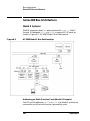
Series 700 Bus Architecture . . . . . . . . . . . . . . . . . . . . . . . . . . . . . . . . .
Model 712 . . . . . . . . . . . . . . . . . . . . . . . . . . . . . . . . . . . . . . . . . . . . . .
Model 725/100 . . . . . . . . . . . . . . . . . . . . . . . . . . . . . . . . . . . . . . . . . . .
Model 770 (J Series) . . . . . . . . . . . . . . . . . . . . . . . . . . . . . . . . . . . . . .
256
256
257
259
Series 800 Bus Architecture . . . . . . . . . . . . . . . . . . . . . . . . . . . . . . . . .
Model E Systems . . . . . . . . . . . . . . . . . . . . . . . . . . . . . . . . . . . . . . . . .
Models F/G/H/I and 8x7 Systems . . . . . . . . . . . . . . . . . . . . . . . . . . . .
Models 890 and T500 Systems . . . . . . . . . . . . . . . . . . . . . . . . . . . . . .
Models 8x9 (K Series) . . . . . . . . . . . . . . . . . . . . . . . . . . . . . . . . . . . . .
260
260
262
264
267
C. Major and Minor Numbers
Understanding how the Kernel Associates Drivers to Device . . . . . . . 270
Major Numbers . . . . . . . . . . . . . . . . . . . . . . . . . . . . . . . . . . . . . . . . . . 270
Minor Numbers . . . . . . . . . . . . . . . . . . . . . . . . . . . . . . . . . . . . . . . . . . 271
Understanding the Construction of Device Special Files. . . . . . . . . . . 272
Examples of Minor Number Creation . . . . . . . . . . . . . . . . . . . . . . . . 274
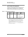
Minor Number Bit Assignments . . . . . . . . . . . . . . . . . . . . . . . . . . . . . . 276
10
Contents
Associating a Custom Driver with a Peripheral . . . . . . . . . . . . . . . . . .284
Creating Device Special Files using mknod . . . . . . . . . . . . . . . . . . . . . .288
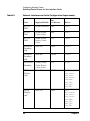
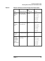
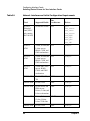
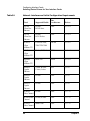
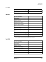
D. Worksheets
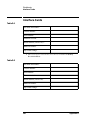
Interface Cards . . . . . . . . . . . . . . . . . . . . . . . . . . . . . . . . . . . . . . . . . . . .290
Terminals and Modems . . . . . . . . . . . . . . . . . . . . . . . . . . . . . . . . . . . . . .291
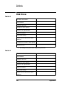
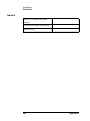
Disk Drives. . . . . . . . . . . . . . . . . . . . . . . . . . . . . . . . . . . . . . . . . . . . . . . .292
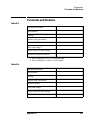
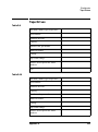
Tape Drives . . . . . . . . . . . . . . . . . . . . . . . . . . . . . . . . . . . . . . . . . . . . . . .295
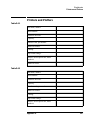
Printers and Plotters . . . . . . . . . . . . . . . . . . . . . . . . . . . . . . . . . . . . . . . .297
Uninterruptible Power Systems (UPS) . . . . . . . . . . . . . . . . . . . . . . . . .299
11
Contents
12
Printing History
The document printing date and part number indicate the document’s
current edition. The printing date will change when a new edition is
printed. Minor changes may be made at reprint without changing the
printing date. The document part number will change when extensive
changes are made.
Document updates may be issued between editions to correct errors or
document product changes. To ensure that you receive the updated or
new editions, you should subscribe to the appropriate product support
service. See your HP sales representative for details.
First Edition: January 1995 (HP-UX Release 10.0)
Second Edition: October 1997 (HP-UX Release 11.0)
Third Edition: January 1999 (HP-UX Release 11.0)
Fourth Edition: January 2000 (HP-UX Release 11.x)
Fifth Edition: November 2000 (HP-UX 11i Release)
13
14
Getting Started
1
Getting Started
Before physically installing a disk drive, tape drive, printer, or other
peripheral device, you must configure the HP-UX operating system to
communicate with it. Configuring HP-UX for Peripherals provides the
software information needed for system administrators to configure the
many peripheral devices supported on HP-UX.
Read this chapter for:
• an overview of peripheral configuration
• explanation of I/O convergence
• explanation of loadable drivers
• syntax of device special file names
• information on associating device special files with their peripheral
devices, by using lssf and ioscan
Keep this document and the following other documents available for
reference when installing and configuring peripheral devices:
•
installation manuals shipped with the device
• HP-UX Managing Systems and Workgroups
• HP-UX Reference
Commands such as mksf, insf, and ioscan (now available on both
Series 700 and 800 systems) make it largely unnecessary to manipulate
the minor number literally. However, if you are configuring a peripheral
for unusual circumstances, you should consult the appendices at the end
of this document.
NOTE
Configuring a peripheral device requires that you operate with root
privileges. In consideration for others on the system, exercise caution
when acting as superuser.
NOTE
HP Interface Bus (HP-IB) and HP Fiber Link (HP-FL) disks and
Chapter 1
15
Getting Started
interface cards are not supported by HP-UX Release 11.0. All such
devices should be removed from your system before installing or
updating to HP-UX Release 11.0.
16
Chapter 1
Getting Started
Peripheral Configuration in its Simplest Terms
Peripheral Configuration in its Simplest
Terms
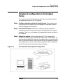
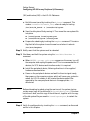
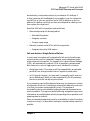
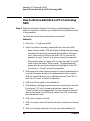
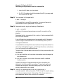
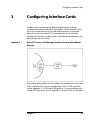
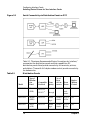
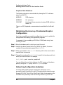
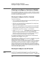
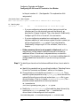
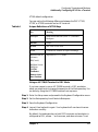
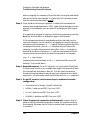
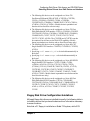
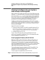
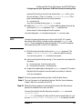
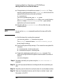
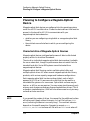
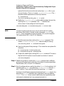
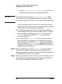
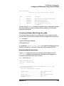
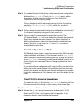
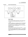
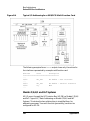
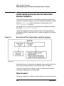
You must perform the following three steps before a peripheral device
can communicate with an HP-UX system:
Step 1. Configure the device driver(s) into the kernel. Device drivers are
like translators that speak both the language of the peripheral device
and the language of the computer.
Step 2. Install the hardware. Perform any hardware-specific installation
procedures required to physically connect the peripheral device to your
computer. Then, turn on the power to the peripheral devices and then to
the computer.
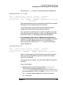
Step 3. Reboot the system. As the system reboots, HP-UX automatically
creates the necessary device special files required for the peripheral. At
least one device special file must exist for a device driver to communicate
with the peripheral device. Device special files tell the operating system
which device driver to use, how to find the peripheral device, and what
special characteristics the peripheral device employs.
Figure 1-1
The Essentials of Peripheral Configuration
Chapter 1
17
Getting Started
Peripheral Configuration in its Simplest Terms
NOTE
Often, if you anticipate having to add a new external peripheral device,
you can configure the device drivers into the kernel at a time when no
one else is on the system. Then, when the peripheral arrives, you can
physically install it with minimal user disruption.
Using SAM to Configure Peripherals
The HP-UX System Administration Manager (SAM) provides the easiest
way to:
• view your system's configuration
• configure the peripheral device's drivers into the kernel
• regenerate the kernel after configuring the software
To invoke SAM, type /usr/sbin/sam.
SAM's user interface and online help system allow you to discover the
configuration information as you proceed through its screens. Once you
provide SAM with basic information about the device being configured,
SAM performs the following tasks:
• checks your currently running kernel configuration file for the
required device drivers
• reports whether or not the drivers are present
• adds the drivers if necessary
• re-configures the kernel
For some devices, SAM also automates other necessary steps. For
example, when adding a terminal to your system, SAM edits the
/etc/inittab file to add the terminal entry. You have to perform this
step manually if you are not using SAM to configure the terminal.
Using HP-UX Commands to Configure Peripherals
You must use HP-UX commands to configure peripherals into the system
if the device cannot be automatically configured or if SAM is not on your
system.
Virtually all Hewlett-Packard disk drives, tape drives, printers, plotters
18
Chapter 1
Getting Started
Peripheral Configuration in its Simplest Terms
and terminals are configurable automatically. Each peripheral-specific
chapter of this document gives procedures for using HP-UX commands
for configuration.
Exceptions: Drivers insf Cannot Recognize
Third-party drivers and certain drivers used for instrumentation or
black-box applications are not recognized by insf, so insf cannot
automatically create device files during the reboot process.
If you are adding a peripheral device requiring a driver that cannot be
configured automatically, you must configure the device driver and
create the device files using the ioscan and mksf or mknod commands.
For guidance in these cases, consult Appendix C , “Major and Minor
Numbers,” at the end of this document Chapter 8, “Configuring Printers
and Plotters,” also has information on configuring instruments that
require manual manipulation.
Chapter 1
19
Getting Started
Understanding I/O Convergence
Understanding I/O Convergence
As of HP-UX Release 10.0, the HP-UX I/O system is largely converged,
allowing for an environment that supports a greater flexibility of bus
architectural combinations. The convergence is seen most dramatically
on Model K (8x9) systems, which have capabilities previously found only
on Series 700 workstations.
From an administrative perspective, I/O convergence means that the
vast majority of configuration tasks are now performed identically,
whether for a Series 700 or Series 800 system. Device file names on both
architectures are consistent (the naming convention is explained in
“Understanding Device Special File Names” on page 23), and drivers
have been streamlined to work in this converged environment.
Think of the drivers as belonging to one of two broad categories,
according to the PA-RISC bus architecture on which they run — the
Server I/O (SIO) system and the Workstation I/O (WSIO) system. The
SIO driver environment includes Series 800 CIO and HP-PB bus
architectures. The WSIO driver environment supports bus architectures
traditionally associated with Series 700 workstations, and provides
greater openness for use of third-party interfaces and devices.
Throughout this document, the terms Series 700 and 800 continue to be
used, as the command uname -m continues to report Series 700 or 800
model numbers. Although we use the terms Series 700 and Series 800
when we describe drivers, we are really implying WSIO or SIO driver
environments. These separate environments permit only those drivers
required by a given bus architecture to be configured into the kernel as
needed (for example, only WSIO drivers on a legacy Series 700 system or
SIO and WSIO drivers on a Series 800 system).
Read the /usr/conf/master.d/core-hpux file to better understand the
architectural context dependencies. Also, consult master (4) in the
HP-UX Reference.
20
Chapter 1
Getting Started
Understanding Loadable Device Drivers
Understanding Loadable Device Drivers
As of HP-UX Release 11.0, a new feature known as Dynamically
Loadable Kernel Module (DLKM) provides the means to add a device
driver to a running UNIX system without rebooting the system or
rebuilding the kernel. This feature also makes it possible to dynamically
remove a device driver from the UNIX system when the driver is no
longer needed, thereby freeing system resources for other use.
The DLKM feature not only provides the infrastructure to load drivers
into a running kernel, but it also allows a driver to be statically linked
into the kernel—the way all drivers were included in the kernel prior to
HP-UX 11.0. Simply setting a flag in one of the driver’s configuration
files determines whether a driver is to be configured as dynamically
loadable or statically linked.
For HP-UX 11.0, the system must be in a run-time state before dynamic
module loading is available. Thus, drivers required during system boot
must be configured as statically linked.
DLKM Module Types
The DLKM feature currently supports the following types of drivers:
WSIO class drivers, WSIO interface drivers, and STREAMS drivers. It
also supports STREAMS modules and miscellaneous modules. An
example of a miscellaneous module is a module containing support
functions not required in the statically configured kernel but shared
among multiple loadable modules.
New Module Packaging
As of HP-UX 11.0, each driver may have its own master and system
files, whereas prior to HP-UX 11.0, the driver shared master files and
had access to a single system file—the HP-UX system file
(/stand/system by default). (The HP-UX system file is still supported in
HP-UX 11.0.) This new way of packaging drivers together with the new
way of writing driver source code is what makes the DLKM feature
possible.
NOTE
See the master (4) manpage for descriptions of the two kinds of master
Chapter 1
21
Getting Started
Understanding Loadable Device Drivers
files, and the config (1M) manpage for a description of the HP-UX system
file.
Advantages of DLKM Drivers
DLKM drivers/modules provide many advantages relative to static
drivers/modules, including:
• making it easier for administrators to install device drivers from
other vendors
• improving system availability by allowing device drivers and other
modules to be configured into the kernel while the system is running
• conserving system resources by unloading infrequently used modules
when not in use
• providing administrators with the ability to demand load and unload
modules
• providing the kernel with the ability to automatically load modules
Auto loading occurs when the kernel detects a particular loadable
module is required to accomplish some task, but the module is not
currently loaded. The kernel automatically loads the module.
NOTE
Auto unloading is not supported in HP-UX 11.0.
22
Chapter 1
Getting Started
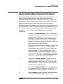
Understanding Device Special File Names
Understanding Device Special File Names
Device special files tell the operating system which device driver to use,
how to find the peripheral device, and what characteristics the
peripheral device should employ. Characteristics vary by device. Thus,
device special files for magneto-optical devices show the surface being
addressed, while those for tape drives show rewind and density.
Most device special file names contain the location of the device on the
bus architecture. To see this, display the files in any subdirectory of the
/dev directory. Note, all mass storage devices adhere to a syntax that
includes c#t#d#[s#] (other kinds of device files use a related
convention):
c#
represents the card instance number for the class of
interface card to which the device is connected. Classes
of interface cards include ext_bus, graphics, tty, lan,
and others. The card instance of an interface card is
unique for its specific class. There is no relationship
between the instance number and the slot number of
the interface card in the card cage.
Class and instance number can be seen in the first two
columns of /usr/sbin/ioscan -f output. When
interpreting a device special file, the only significant
instance number is the card instance (that is, the
instance number for the class of interface to which a
device is attached). Thus, in a sample disk device file
/dev/rdsk/c1t4d0, the c1 refers to the card instance,
not to an LU number (as in previous releases).
t#
represents the target address of the device on the
interface bus. The address can range from 0 to 7 for a
single-ended device, and from 0 to 15 for a fast wide
device. Typically t# is the address set with jumpers or
dip switches on the device itself.
d#
represents the device number, and can range from 0
to 7 maximum. On SCSI devices, d# is the SCSI LUN.
Except for multi-function devices, d# is typically d0.
s#
specifies section number (optional; made available for
backward compatibility). Note, section 0 now
Chapter 1
23
Getting Started
Understanding Device Special File Names
represents the entire disk, while section 2 represents a
small disk section (previously section 0). If the s# is not
shown, the device special file refers to the entire disk.
Sample Device Special File Names
Every peripheral-specific chapter in this document has tables of
configuration requirements that show the default device special file
names for that class of device. Here are some sample device special files
and their possible meanings:
/dev/rdsk/c0t6d0
Entire disk accessed in character
(raw) mode through SCSI card
instance 0, target 6, LUN 0.
/dev/rac/c0t0d0_11a
Surface 11a of a magneto-optical disk
whose auto changer in a disk library
accessed in raw mode through card
instance 0, target 0, LUN 0.
/dev/rmt/c1t0d0BESTnb
Tape drive accessed through card
instance 1, target 0, LUN 0. Tape
writes at best available
density/format, no rewind,
Berkeley-style close.
/dev/rmt/0mnb
Tape drive device special file with
identical characteristics (linked) to
/dev/rmt/c1t0d0BESTnb.
/dev/floppy/c1t3d0
Entire floppy disk drive accessed in
block mode through SCSI card
instance 1 located in slot 13, with
target 3, LUN 0.
/dev/tty0p0
Serial port of built-in card instance 0
port 0, hard wired at address 56.0;
accessed through driver mux4.
/dev/c1t0d0_lp
Parallel port on core I/O card 1, set to
handshake mode 2.
/dev/lp
Parallel port on core I/O card 1, set to
handshake mode 2; device file is
linked to /dev/c1t0d0_lp.
Both lssf and ioscan commands display the interface to which a device
24
Chapter 1
Getting Started
Understanding Device Special File Names
is connected. These are discussed in the next sections.
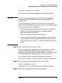
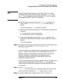
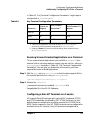
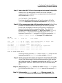
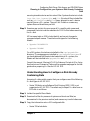
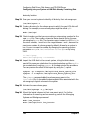
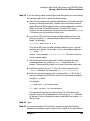
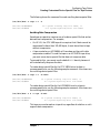
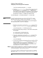
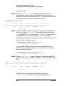
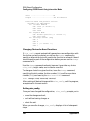
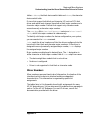
Decoding Device Special Files with lssf
Use the /usr/sbin/lssf command to decode device special files. The
following figure compares ll and lssf output.
NOTE
Throughout this document, examples of commands usage are shown as
command text.
ll /dev/rac/c1t1d0_2a
crw-rr
1 root
users
230 0x011003 May 3 16:46 /dev/rac/c1t1d0_2a
/usr/sbin/lssf /dev/rac/c1t1d0_2a
autox0 card instance 1 SCSI target 1 SCSI LUN 0 optical disk 2 side a
at address 52.1.0 /dev/rac/c1t1d0_2a214
ll /dev/rmt/c0t1d0NOMOD
crw-rwrw
1 bin
bin
205 0x00100f May 4 11:31 /dev/rmt/c0t1d0NOMOD
/usr/sbin/lssf /dev/rmt/c0t1d0NOMOD
stape card instance 0 SCSI target 1 SCSI LUN 0 at&t keep existing density/format
at address 2/0/1.1.0 /dev/rmt/c0t1d0NOMOD
ll /dev/rmt/c0t1d0BESTb
crw-rwrw
2 bin
bin
205 0x001080 Apr 28 17:24 /dev/rmt/c0t1d0BESTb
/usr/sbin/lssf /dev/rmt/c0t1d0BESTb
stape card instance 0 SCSI target 1 SCSI LUN 0 berkeley best density available
at address 2/0/1.1.0 /dev/rmt/c0t1d0BESTb
Chapter 1
25
Getting Started
Viewing the System Configuration with ioscan
Viewing the System Configuration with ioscan
The /usr/sbin/ioscan command is the single most versatile tool in
HP-UX for displaying your system configuration. For example, you can
use ioscan to identify available hardware addresses.
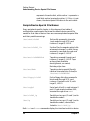
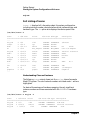
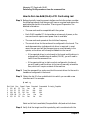
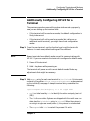
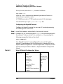
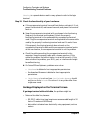
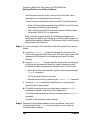
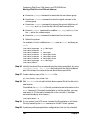
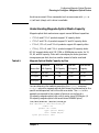
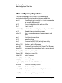
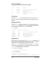
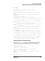
Terse Listing of ioscan
In its simplest form, /usr/sbin/ioscan displays hardware path, device
class, and description. The -u (usable device) or -k (kernel structure)
option gives fastest response, because neither option probes the
hardware.
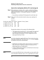
The following example shows devices on a Series 800 Model E, connected
through the HP-PB bus converter at address 56. The 56/52 is the
address of the single-ended SCSI interface. The shaded digits below are
the addresses already being used on the card. Note that there is no
56/52.4.0. If you attach another SCSI device to this card, you can set its
address to 4.
/usr/sbin/ioscan -k
H/W Path
Class
Description
==========================================
56
bc
Bus Converter
56/52
ext_bus
HP 28655A - SCSI Interface
56/52.0
target
56/52.0.0
tape
SCSI Tape
56/52.1
target
56/52.1.0
disk
HP C2247M1 - SCSI Disk
56/52.2
target
56/52.2.0
disk
HP C2247M1 - SCSI Disk
56/52.3
target
56/52.3.0
disk
TEAC FC-1 ... - SCSI Disk
56/52.5
target
56/52.5.0
disk
HP C2247M1 - SCSI Disk
56/52.6
target
56/52.6.0
disk
HP C2247M1 - SCSI Disk
...
Understanding Hardware Addresses
You can identify each piece of hardware configured to an HP-UX
computer by its hardware address (shown in ioscan as H/W Path).
26
Chapter 1
Getting Started
Viewing the System Configuration with ioscan
The length of these numerical sequences differ by system model and
architecture, but every hardware path leads you through the bus
structure, starting from the bus closest to the system processor and
ending at the output device.
ioscan -H hardware_path shows you the sequence of connection to or
from the specified location. In the following example, which displays
output from a Model 770, a disk attached to the GSC built-in Fast/Wide
SCSI Interface has the hardware address 8/0.5.0.
/usr/sbin/ioscan -H 8/0.5.0
H/W Path
Class
Description
====================================================
bc
8
bc
I/O Adapter
8/0
ext_bus
GSC built-in Fast/Wide SCSI Interface
8/0.5
target
8/0.5.0
disk
DEC
DSP3210SW
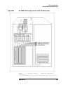
The hardware path can be decoded as follows:
8
identifies the bus adapter connecting the GSC+ bus to
the system bus.
0
identifies the slot number of the Fast/Wide SCSI
interface. (See Figure B-3 in Appendix B, Bus
Architectures.)
5
represents the "target," or SCSI address, set on the
disk device itself.
0
indicates a unit number or SCSI LUN number.
Field separators slash (/) and dot (.) separate the numbers of the
hardware address and have no bearing on system administration. The
displayed classes are more meaningful in the context of instance
numbers, which are visible in ioscan -f listings, and will be discussed
shortly. Explanation of hardware addresses on multi-function cards is in
Appendix B , “Bus Architectures.”
Understanding the Description in ioscan
The description field displayed by ioscan derives from the peripheral
device itself. Typically, a numeric description refers to the
manufacturer's vendor ID, and in some cases, this number corresponds
to more than one model number. If you are troubleshooting a peripheral’s
problem, the description is often useful information to an HP support
Chapter 1
27
Getting Started
Viewing the System Configuration with ioscan
engineer.
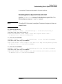
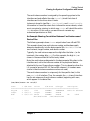
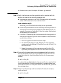
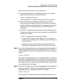
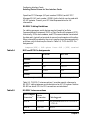
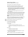
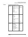
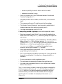
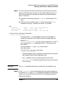
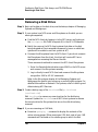
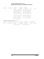
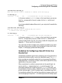
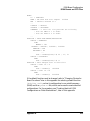
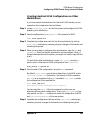
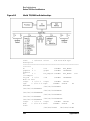
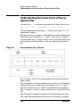
Full Listing of ioscan
ioscan -f displays full information about the system configuration,
including instance number, device/interface driver, software state, and
hardware type. The -fn option also displays the device special files.
/usr/sbin/ioscan -f
Class
I H/W Path
Driver
S/W State H/W Type
Description
========================================================================
...
ext_bus
0 8/0
c720
CLAIMED INTERFACE
F/W SCSI
target
0 8/0.5
tgt
CLAIMED DEVICE
disk
0 8/0.5.0
sdisk
CLAIMED DEVICE
HP
C2247
ba
0 8/12
bus_adapter CLAIMED BUS_NEXUS
Core I/O Adapter
ext_bus
2 8/12/0
CentIf
CLAIMED INTERFACE
Parallel Interface
audio
0 8/12/1
audio
CLAIMED INTERFACE
Audio
tty
0 8/12/4
asio0
CLAIMED INTERFACE
RS-232C
ext_bus
1 8/12/5
c700
CLAIMED INTERFACE
SCSI
target
1 8/12/5.0
tgt
CLAIMED DEVICE
disk
1 8/12/5.0.0
sflop
CLAIMED DEVICE
TEAC
FC-1
...
lan
0 8/12/6
lan2
CLAIMED INTERFACE
LAN
bc
2 10
ccio
CLAIMED BUS_NEXUS
I/O Adapter
graphics
0 10/0
graph3
CLAIMED INTERFACE
Graphics
...
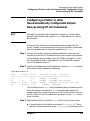
Understanding Class and Instance
The following ioscan output shows just the ext_bus class of a sample
Model 770 system. The card instance numbers are listed under I and are
highlighted.
For device file naming and hardware mapping, the only significant
instance numbers are those associated with the INTERFACE hardware
type.
/usr/sbin/ioscan -C ext_bus -f
Class
I H/W Path Driver
S/W State H/W Type Description
=====================================================================
ext_bus
0 8/0
c720
CLAIMED INTERFACE
F/W SCSI
ext_bus
2 8/12/0
CentIf
CLAIMED INTERFACE
Parallel Interface
ext_bus
1 8/12/5
c700
CLAIMED INTERFACE
SCSI
28
Chapter 1
Getting Started
Viewing the System Configuration with ioscan
The card instance number is assigned by the operating system to the
interface card and reflects the order ioconfig binds that class of
interface card to its driver when it boots.
Instance is stored in two files — /etc/ioconfig and /stand/ioconfig.
Information in these files retain their information across reboots, unless
one is corrupted or missing, in which case, ioinit will rebuild the entire
/dev structure. (If this occurs, you would have to recreate any
customized permissions or files.)
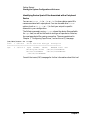
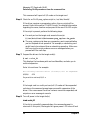
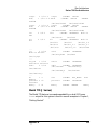
An Example Showing Correlation Between Card Instance and
Device Files
The following example shows ioscan output taken from a Model 735.
This example shows how card instance number and hardware path
elements map directly into the device special file /dev/dsk/c1t5d0 as
card instance, target number, and device number.
Typically, the card instance maps as the digit after the letter c (or for
terminals, the number after tty). For this example, the digit is 1, as
shown in the second field of the first entry below.
Note, the card instance designated in the device special file refers to the
interface card, not to the instance number of the peripheral device
attached to the card. (Ignore those numbers. This is a departure from the
LU concept of previous HP-UX Series 800 releases. LU numbers were
similar to device instance numbers and are not used.)
The card instance number is unique only for the specific class (in this
case, ext_bus) of interface. Thus, for example, the tty class of interface
has its own sequence of card instance numbers, beginning with zero,
which appear in its device files.
/usr/sbin/ioscan -fn -H 2/0/7
Class
I H/W Path
Driver
S/W State
H/W Type
Description
===========================================================================
ext_bus
1 2/0/7
c700
CLAIMED
INTERFACE
Built-in F/W SCSI
target
3 2/0/7.5
target
CLAIMED
DEVICE
disk
2 2/0/7.5.0 sdisk
CLAIMED
DEVICE
HP
C2247
/dev/dsk/c1t5d0
/dev/rdsk/c1t5d0
...
Chapter 1
29
Getting Started
Viewing the System Configuration with ioscan
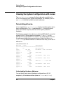
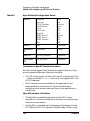
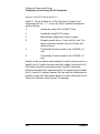
Identifying Device Special Files Associated with a Peripheral
Device
You can use ioscan -fn (or -fkn or -fun) to show device special file
names associated with a peripheral. You can also add other ioscan
options (such as -H, -C, -d, or -I) to limit your output to specific
elements in your configuration.
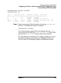
The following example, using -C tape, shows the device files available
for tape class, as well as the location and type of tape device. Note too,
the new tape device file naming convention. These are explained in
Chapter 7, “Configuring Tape Drives,” and on the mt (7) manpage.
/usr/sbin/ioscan -fn -C tape
Class
I H/W Path
Driver S/W State H/W Type Description
============================================================
tape
0 56/52.0.0 tape2 CLAIMED
DEVICE
WANGTEK 51000 SCSI
/dev/diag/rmt/c0t0d0
/dev/rmt/c0t0d0BESTn
/dev/rmt/c0t0d0BEST
/dev/rmt/c0t0d0BESTnb
/dev/rmt/c0t0d0BESTb
Consult the ioscan (1M) manpage for further information about this tool.
30
Chapter 1
Getting Started
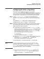
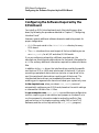
Configuring HP-UX for any Peripheral (A Summary)
Configuring HP-UX for any Peripheral (A
Summary)
Prepare by gathering information required for the successful
configuration of the peripheral. Considerations vary and are discussed in
each peripheral-specific chapter. For example:
• Have you prepared the physical location for the peripheral device?
• To what interface are you connecting the peripheral?
• What device drivers are required by the peripheral device?
In virtually all cases, the System Administration Manager (SAM)
provides the simplest interface for configuring HP-UX for any standard
peripheral device. If you must use the command line interface instead of
SAM, the following procedure will familiarize you with the task.
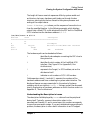
Step 1. Determine the device drivers needed for your peripheral device and
interface by consulting the tables in the chapter devoted to that class of
peripheral device. If any necessary static device driver is absent from the
kernel, you will need to rebuild the kernel to include it.
Here is how to rebuild the kernel:
a. Change directory to the build environment (/stand/build). There,
execute a system preparation script, system_prep. system_prep
writes a system file based on your current kernel in the current
directory. (That is, it creates /stand/build/system.) The -v provides
verbose explanation as the script executes.
cd /stand/build
/usr/lbin/sysadm/system_prep -v -s system
b. Modify the /stand/build/system file to add the absent driver(s) by
invoking the kmsystem command. The -c Y specifies that
driver-name is to be configured into the system.
/usr/sbin/kmsystem -S /stand/build/system -c Y driver-name
NOTE
To avoid introducing format errors, do not edit the HP-UX system
description files directly. Instead, use the commands kmsystem and
kmtune. These commands are new for Release 11.0; consult kmsystem
Chapter 1
31
Getting Started
Configuring HP-UX for any Peripheral (A Summary)
(1M) and kmtune (1M) in the HP-UX Reference.
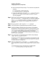
c. Build the new kernel by invoking the mk_kernel command. This
creates /stand/build/vmunix_test, a kernel ready for testing.
/usr/sbin/mk_kernel -s /stand/build/system
d. Save the old system file by moving it. Then move the new system file
into place.
mv /stand/system /stand/system.prev
mv /stand/build/system /stand/system
e. Prepare for rebooting by invoking the kmupdate command. This sets a
flag that tells the system to use the new kernel when it restarts.
/usr/sbin/kmupdate
Step 2. Notify users that the system must be rebooted.
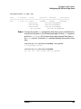
Step 3. Shut down and halt the system using the /usr/sbin/shutdown -h
command.
a. When HALTED, you may cycle power appears on the screen, turn off
the computer and unplug the power cord. This is recommended for all
devices; for SCSI devices and interface cards, it is required.
b. Install the peripheral device, following directions in the supplied
hardware documentation.
c. Power on the peripheral devices and wait for them to signal ready;
then power on the computer system, which will cause your system to
reboot. As HP-UX reboots, it will create the device special files
required by the new peripheral device in the appropriate /dev
directories.
NOTE
Before attempting to reboot using the new kernel, the system startup
scripts save a copy of the old kernel in /stand/vmunix.prev. If the new
kernel won't boot, use this copy of the old kernel, together with the copy
of the old system file you saved in /stand/system.prev, to restart the
system.
Step 4. Verify the configuration by invoking the ioscan command, as discussed
earlier in this chapter.
32
Chapter 1
2
Managing PCI Cards with OLAR
This chapter contains the procedures for adding and replacing PCI cards
using OLAR using SAM and rad along with concepts common to both.
33
Managing PCI Cards with OLAR
How is the information in this chapter structured?
How is the information in this chapter
structured?
This chapter has been split into three sections. This divides the material
in a way that is suitable for testing:
1. SAM and rad (general information for either category)
This contains PCI Card OLAR Overview and Concepts.
2. SAM Procedures
• How to On-Line Replace (OLR) a PCI Card using SAM
• How to On-Line Add (OLA) a PCI Card using SAM
3. rad Procedures
• How to On-Line Replace (OLR) a PCI Card using rad
• How to On-Line Add (OLA) a PCI Card using rad
34
Chapter 2
Managing PCI Cards with OLAR
PCI Card OLAR Overview and Concepts
PCI Card OLAR Overview and Concepts
Introduction
The letters O, L, A and R stand for On Line Addition [and] Replacement.
This, of course, refers to the ability of a PCI I/O card to be replaced
(removed and/or added) to an HP-UX computer system designed to
support this feature without the need for completely shutting down, then
re-booting the system or unnecessarily affecting other system
components. The system hardware uses per-slot power control combined
with operating system support to enable this feature.
Initially, not all add-in cards will have this capability but over time users
should see many cards adding this capability to their set of functions.
IMPORTANT
Certain “Classes” of hardware are not intended for access by users. At
this time this includes V-Class and Superdome systems. HP recommends
that these systems only be opened by a qualified HP Engineer. Failure to
observe this requirement can validate any support agreement or
warranty to which the owner might otherwise be entitled.
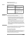
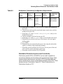
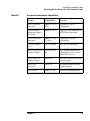
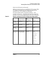
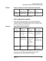
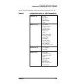
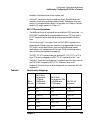
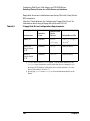
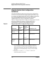
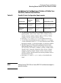
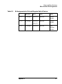
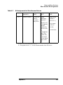
Important Terms and Concepts
Table 2-1
Terms used in this section
Term
Meaning
OLAR
All aspects of the OLAR feature
including On-line Addition (OLA)
and On-line Replacement (OLR).
Power Domain
A grouping of 1 or more interface
card slots that are powered on or off
as a unit. Current systems have one
slot per power domain.
Chapter 2
35
Managing PCI Cards with OLAR
PCI Card OLAR Overview and Concepts
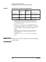
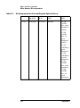
Table 2-1
IMPORTANT
Terms used in this section
Term
Meaning
target card / target card slot
The interface card which will be
added or replaced using OLAR, and
the card slot it resides in.
affected card / affected card slot
Interface cards and the card slots they
reside in which are in the same power
domain as the target slot. Currently
multi-slot power domains are not
implemented.
In many cases, other interface cards and slots within the system are
dependent upon the target card. For example:
• If the target card is a multiple-function card (MFC), suspending
drivers for the target card slot also suspends individual drivers for
the multiple hardware paths on that card. If the target card has
multiple ports, then all individual ports will be suspended and then
resumed when the card is replaced.
• In currently shipped systems, a power domain consists of a single
card slot, however future systems may provide multi-card power
domains. In this case, if the target card slot is in a multi-card power
domain and you temporarily stop power to the target card slot, you
will also stop power to any other card slots (affected card slots) in that
same power domain.
During a card replacement, SAM performs a Critical Resource Analysis,
which checks all ports on the target card for critical resources that would
be temporarily unavailable while the card is shut down.
Planning and Preparation
For the most part SAM prevents you from performing OLAR procedures
that would adversely affect other areas of the server. This section
provides you with important information that can help minimize errors
or problems when performing OLAR procedures.
36
Chapter 2
Managing PCI Cards with OLAR
PCI Card OLAR Overview and Concepts
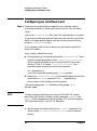
Card Compatibility
On-Line Addition (OLA) When on-line adding an interface card, the
first issue that must be resolved is whether the new card is compatible
with the system. Each OLAR-capable PCI slot provides a set amount of
power. The replacement card cannot require more power than is
available. Current systems have only one slot per bus with sufficient
power.
The card must also operate at the slot’s bus frequency. A PCI card must
run at any frequency lower than its maximum capability, but a card that
could only operate at 33 MHz would not work on a bus running at 66
MHz. Both rad and SAM provide information about the bus frequency
and power available as well as other slot-related data.
When the replacement card is added to the system, the appropriate
driver for that card must be configured in the kernel before beginning
the operation. In most cases, the replacement card will be the same type
as a card already in the system, and the driver will be in the kernel. If
you have any question about the driver’s presence, use the “Kernel
Configuration” area of SAM to determine which drivers are loaded in the
kernel. If the required driver is not in the kernel, but is dynamically
loadable, it should be loaded from this area of SAM before starting the
OLA operation. If the required driver is not present, and is not
dynamically loadable, a reboot will be required to load the driver. The
card could be added while the system is down, or added on-line after
rebooting.
• If the necessary driver is not present and the driver is a dynamically
loadable kernel module (DLKM), you can load it manually. Refer to
the section Dynamically Loadable Kernel Modules in this chapter for
more information.
• If the driver is static and not configured in the kernel, then the card
cannot be On-line Added. The card could be physically inserted
on-line, but no driver would claim it.
On-Line Replacement (OLR) When on-line replacing an interface
card, the replacement card must be either identical (this is the safest
option) or able to use the same driver as the card being replaced. This is
referred to as like-for-like replacement and should be adhered to because
using a similar but not identical card may cause unpredictable results.
For example, a newer version of the target card which is identical in
terms of hardware may contain an updated firmware version that could
Chapter 2
37
Managing PCI Cards with OLAR
PCI Card OLAR Overview and Concepts
potentially conflict with the current driver. If a new card is not
acceptable, SAM or rad will report that the card cannot be resumed.
• During the replacement process, the driver instance for each port on
the target card runs in a suspended state. I/O to the ports are either
queued or failed while the drivers are suspended. When the
replacement card is brought on-line, the driver instances resume
normal operation. Each driver instance must be capable of resuming
and controlling the corresponding port on the replacement card.
The PCI specification allows a single physical card to contain more than
one port. For example, a single-port SCSI bus adapter can not be
replaced by a dual-port adapter, even if the additional port on the card
was identical to the original SCSI bus adapter. Attempting to replace a
card with another card that has more ports than the original could result
in the additional port(s) being claimed by other drivers if an ioscan
occurs while the slot power is on. Recovering from that condition would
require a system reboot.
Critical Resources
Replacing a card that is still operating can have extensive ramifications.
Since power to the slot must be off when the old card is removed and the
new card is inserted, the effects of shutting down the card’s functions
must be considered.
This is particularly important if there is no on-line fail-over or backup
card to pick up those functions. For example:
• Which mass storage devices will be temporarily disconnected when
the card is shut down?
• Will a critical networking connection be lost?
A critical resource is one that would cause a system crash or prevent the
operation from successfully completing if the resource were temporarily
suspended or disconnected. For example, if the SCSI adapter to be
replaced connects to the un-mirrored root disk or swap space, the system
will crash when the card is shut down.
During an OLAR procedure, it is essential to check the targeted card for
critical resources, as well as the effects of existing disk mirrors and other
situations where a card’s functions can be taken over by another card
that will not be affected.
Fortunately SAM performs a thorough critical resource analysis
38
Chapter 2
Managing PCI Cards with OLAR
PCI Card OLAR Overview and Concepts
automatically, and presents options to you based on it’s findings. If
critical resources will be affected by the procedure, you can replace the
card off-line, or you can use either rad or SAM to perform an on-line
addition of a backup card that can then be configured as a backup, and
then replace the target card.
Note that SAM will only analyze cards as follows:
• Mass storage cards will be analyzed for:
— Mounted file systems
— Usage by a process
— Dump or swap usage
• Network interface cards (NICs) will be analyzed for:
— Usage by the active SAM session
Fail-over Actions / Single Points of Failure
In most cases, the system will automatically fail over to the alternate
resource when a card is suspended. However, some subsystems might
require manual intervention. For example, the Logical Volume Manager
(LVM), will automatically redirect I/O for a temporarily disconnected
disk resource to a mirror, logging errors as it handles this situation.
• Along those lines, if the resource will be suspended for an extended
period of time, a large number of error log entries could result.
• In this type of situation, you may want to manually switch over to a
mirror beforehand. When you have completed the OLAR procedure,
the mirror and disk can be re synchronized.
If you suspend a card and the backup takes over, the system can contain
a single point of failure. If the backup resource fails before the new card
is on-line, the system could potentially crash. This window of
vulnerability can be minimized by keeping the period of suspension as
short as possible. This requires careful planning, and gathering as much
information as possible before actually suspending driver operation and
powering-down a card slot.
When an extended suspension period is unavoidable, or when the system
is mission-critical, it is desirable to configure a second backup resource if
possible.
Chapter 2
39
Managing PCI Cards with OLAR
PCI Card OLAR Overview and Concepts
OLAR Scripts
At various stages throughout most OLAR procedures, SAM may initiate
certain actions that notify the system of the addition or replacement of
an interface card.
• These actions are contained in OLAR scripts, which are developed by
software driver engineers and based on the application or system
requirements for the target interface card.
• There are one or more scripts per device (if required; some devices
may not require scripts). See the following descriptions for details.
• Scripts are run by SAM and for the most part do not require user
intervention.
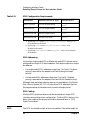
OLAR Script Actions
Pref-OLAR (Preface Operations) Actions
Pref-OLAR scripts are run by SAM to determine and report the
ramifications of operation suspension (e.g., applications using resources)
and whether or not a I/O node can be made inactive for replacement.
(The task of making a I/O node inactive is performed in the prep-OLAR
scripts.)
Prep-OLAR (Prepare Operations) Scripts
Prep-OLAR scripts are run by SAM just prior to suspending software
driver operations, as the first step in a PCI controller card replacement.
These scripts contain the necessary instructions to bring the target
resource out of service, before activity to and from the device is actually
stopped. For example, a prep-replace script may checks for token ring
presence, high-availability features, switch over, and/or available backup
mechanisms.
NOTE
A script is delivered with the card driver and is located in the directory
/usr/sbin/olrad.d/. It does any preparatory work required before the driver
suspends operation. If the driver requires no preparatory action, then no
script will be executed.
When a prep-OLAR script is run, the subsequent actions are “forced.”
That is, subsequent commands are expected to succeed. If the script
40
Chapter 2
Managing PCI Cards with OLAR
PCI Card OLAR Overview and Concepts
encounters errors are encountered, it will attempt to resume operations
at the point where it started.
Post OLAR (Post Operations) Scripts
Post-OLAR scripts are run by SAM just after a PCI card is added or
replaced, and initialized. These scripts contain the necessary
instructions to bring the replaced card into service before activity to and
from the device is actually started or re-started. For example, a post_add
script might create special device files for the new card and any attached
devices.
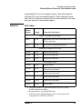
IMPORTANT ADVANCED CONSIDERATIONS
This section presents other situations that you are likely to encounter
when performing OLAR operations, and how to handle them accordingly:
• Power Domains
• Multi-port Cards
• Virtual Ports
• Patch Information
Power Domains
A power domain is a grouping of 1 or more interface card slots that are
powered on or off as a unit. As of this release, there are no systems that
support more than 1 interface card slot in a single power domain. For
future releases where multiple cards per power domain are supported,
SAM and rad will account for them.
SAM will not allow an OLAR action to take place for a card if any
member of its power domain is a critical resource.
Multi-port Cards
Some PCI cards may provide more than one function. These multi-port
cards have separate hardware paths for each port, as well as separate
drivers bound at each hardware path.
Both SAM and rad will account for multi-port cards, and will either
suspend or resume all ports associated with a slot. SAM will account for
all ports during critical resource analysis and will run scripts for all
ports when necessary.
Chapter 2
41
Managing PCI Cards with OLAR
PCI Card OLAR Overview and Concepts
Virtual Ports
Some driver designs create “virtual” ports that do not directly correspond
to any physical hardware. Virtual ports can normally be identified by the
driver that controls them. For example, HP Fibrechannel Mass Storage
card drivers create virtual ports with drivers named “fcp”, “fcpdev”,
“fcparray”, and “fcpmux” to control different aspects of the fibrechannel
mass storage network to which they are attached.
Both SAM and rad do not explicitly list virtual ports when discussing
topics that affect physical ports, however both types of ports are
suspended and resumed as appropriate.
Since virtual ports are reported by ioscan, they will appear in the
Peripheral Devices -> Cards area of SAM with the same slot ID as their
corresponding physical port.
Firmware Patch Information
For those wishing to use OLAR, your system may need to update its
firmware. For additional details, please refer to the Readme Before
Installing or Updating to HP-UX 11i document provided with your HP
product.
42
Chapter 2
Managing PCI Cards with OLAR
How to On-line Replace (OLR) a PCI Card using SAM
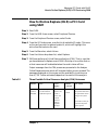
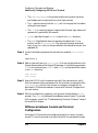
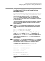
How to On-line Replace (OLR) a PCI Card
using SAM
Step 1. Start SAM.
Step 2. From the SAM Areas screen, select Peripheral Devices.
Step 3. From the Peripheral Devices screen, select Cards.
Step 4. From the I/O Cards screen, view the list of available I/O cards. Click once
on the card you wish to replace to select it, which will highlight the
entire line that contains the card.
Step 5. From the Menu bar, select Actions.
Step 6. From the Actions drop-down list, select Replace.
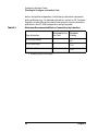
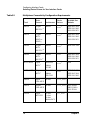
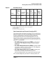
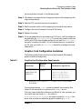
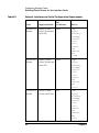
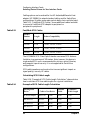
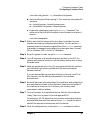
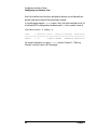
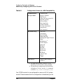
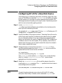
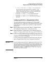
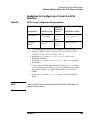
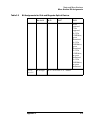
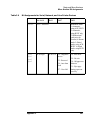
Step 7. SAM now performs a Critical Resource Analysis (CRA). That is, now that
you have selected to Replace a card, SAM’s first step is to confirm that no
critical resources will be disabled when the card is taken off-line.
Output messages from the CRA process are presented in the Analyze
Critical Resources screen which will be shown before you can proceed. The
messages displayed on this screen and the availability to continue on
from it (“OK” button activated) depend on the results of the analysis.
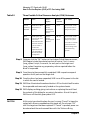
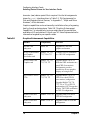
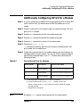
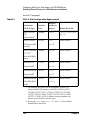
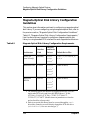
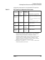
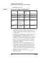
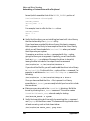
Table 2-2
Three Possible Critical Resource Analysis (CRA) Outcomes
Outcome
Notes
Screen
Displays
Buttons
Activated
User Actions
No critical
resources
identified.
At this point, you
can still cancel the
replacement process.
“No affected
resources are
critical or
in-use” and
“Critical
Resource
Analysis
complete”
messages.
OK and
Click “Cancel” to halt
the operation and cancel
the replacement with no
change to the system.
Or,
Chapter 2
Cancel
Click “OK” to take you
to the next step in the
replace process.
43
Managing PCI Cards with OLAR
How to On-line Replace (OLR) a PCI Card using SAM
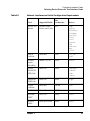
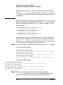
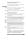
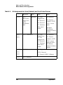
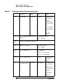
Table 2-2
Three Possible Critical Resource Analysis (CRA) Outcomes
Outcome
Notes
Screen
Displays
Buttons
Activated
User Actions
Critical
resource(s)
identified.
SAM will not allow
the operation to
proceed.
Detailed
message
describing the
affected critical
resource.
Cancel
Click “Cancel” to halt
the operation with no
change to the system
Other
resources
identified.
SAM reports other
resources that are in
use with no
detectable alternates.
For these resources,
you can cancel or
continue the
operation based on
your knowledge of
the current system
configuration.
Detailed
message
describing these
resources.
OK and
Click “Cancel” to halt
the operation with no
change to the system.
Cancel
Click “OK” to continue
operations based on
your knowledge of the
information being
reported.
Step 8. Once you click the “OK” button on the Analyze Critical Resources screen,
SAM begins to take the selected card out of service. First, it runs a
“prep_replace” script, if one exist, for each port on the target card.
“prep_replace” executes any preparatory actions required before the
driver is suspended.
Step 9. Once the script has successfully completed, SAM requests a suspend
operation for all ports on the target card.
Step 10. Once the driver has been suspended, SAM turns off the power to the slot
in which the card is located.
Step 11. SAM then illuminates the amber attention LED on the slot itself to make
the suspended card more easily located on the system chassis.
Step 12. SAM displays a dialog giving instructions on replacing the card. Read
the contents of this dialog for any extra information. Also at this point,
SAM turns off the slot’s green power LED.
CAUTION
At this point you should replace the card, or press “Cancel” to leave the
system with drivers suspended and slot power off. Do not press “OK”
until the target card has been replaced. If “Cancel” is pressed, power can
be restored and the card resumed later with the “Actions->Bring
44
Chapter 2
Managing PCI Cards with OLAR
How to On-line Replace (OLR) a PCI Card using SAM
On-Line” menu item.
Step 13. Replace the target card. The exact procedure for doing this will depend
on what system class you have. Please refer to the hardware manual for
your system for detailed information.
Step 14. At this point, the amber LED should still be activated, and the green
power LED should still be off.
Return to the console, and click the “OK” button on the Replace Card
dialog.
Step 15. Once you click “OK”, SAM first resets the attention LED to it’s normal
state.
Step 16. SAM completes the operation by reversing the sequence of actions. That
is, SAM will:
a. return power to the card slot
b. resume driver operations to the card
c. run any post-replacement scripts (if exist)
Chapter 2
45
Managing PCI Cards with OLAR
How to On-line Add (OLA) a PCI Card using SAM
How to On-line Add (OLA) a PCI Card using
SAM
Step 1. Read the information (below) in this step. An understanding of this
section is important in order for you to make the correct decision(s) later
in the procedure.
You have two choices when performing an on-line add.
Method 1:
1. Enter the I/O Cards area of SAM.
2. Insert the card into an empty, powered-off slot, then enter SAM.
• Select “Actions->Add”. SAM will display a dialog listing the empty
slots and slots containing unclaimed cards (listed as “unknown
card”. Select a slot on the list then press “OK” to continue the
operation, or press “Cancel” at any time to cancel the operation.
• Alternatively, select an “empty slot” or “unknown card” on the I/O
cards screen, then select “Actions->Add”. The same dialog will
appear, with the previously selected slot highlighted. Press “OK”
to continue, or “Cancel” to cancel the operation.
3. SAM performs a critical resource analysis. Unless the selected slot is
in a multi-slot power domain (not implemented as of this release),
SAM will report that there are no affected resources. Press “OK” to
continue, or “Cancel” to cancel the operation.
4. SAM turns off the power to the selected slot.
5. SAM displays a dialog giving instructions on inserting the new card.
Do not press “OK” until the new card has been inserted. Press
“Cancel” to leave the slot powered off. The new card can be inserted
later and activated using “Method 2” below. Press “OK” to continue
with the operation now.
6. SAM turns on power to the slot.
7. SAM runs ioscan, which will bind the drivers to the ports on the new
card.
8. SAM runs the post_add script, if any, for any newly added port it
46
Chapter 2
Managing PCI Cards with OLAR
How to On-line Add (OLA) a PCI Card using SAM
finds.
NOTE
At this point, the OLA is complete. Note that in some cases additional
configuration in another area of SAM may also be required. A network
interface card, for example, might require network parameter setup in
the Network Interface Card portion of the Networking and
Communications area. After adding a card, SCSI host bus adapters are
configured with default values for parameters, such as SCSI ID. This
may cause SCSI ID conflicts if the card is connected to a shared SCSI
bus, where another host bus adapter has the same ID.
Method 2:
1. Enter the I/O Cards area of SAM.
2. Select any empty slot.
3. Select “Actions->Power Off Slot”. Unless the slot is in a multi-slot
power domain (not supported in this release), SAM will display a
dialog indicating that no ports are associated with the slot, and ask if
you want to continue to power off the slot. Press “Yes” to continue or
“No” to cancel the operation. If “Yes” is pressed, SAM will turn off
power to the slot.
4. Optionally, select the same slot and select “Actions->Light Slot LED”.
SAM will display a dialog indicating that the LED is on. If you want
to leave the LED on to help you locate the slot, do not press OK until
you have inserted the new card.
5. Insert the card into the correct slot.
6. Press “OK” on the “Light Slot LED” dialog. SAM will turn off the slot
LED.
7. Select “Options->Refresh View”. The empty slot into which the card
was inserted will display as an “unknown card”.
8. Select that “unknown card”, then select “Actions->Bring On-Line”.
SAM powers on the slot and activates the new card as described in
method 1 above.
Chapter 2
47
Managing PCI Cards with OLAR
Performing OLAR procedures from the command line
Performing OLAR procedures from the
command line
This Critical Resource Analysis feature is not available from the
command line (rad), so it is the responsibility of the engineer or system
administrator to ensure that other system services are not interrupted
during OLAR command line procedures.
• Extreme care should be taken when using rad, since the command
will, in most cases, attempt to complete the operation. For example,
running the command: rad -s slotid , will suspend the driver
instances for every I/O node controlled by that slot, even if you only
wanted to suspend one driver instance (for example, as with a multi
function card). Review and choose command line options carefully.
• The section “Analyzing Critical Resources” presents a high-level list
of steps you can take to help you determine critical dependencies.
Although these steps are incorporated into the Add and Replace
procedures that follow, reviewing this section will give you a better
understanding of the scope of an OLAR operation.
• In order to ensure a thorough critical resource analysis when
performing any OLAR procedure using rad, procedure steps should be
performed and completed in the exact sequence presented.
Analyzing Critical Resources
A critical resource is one that would cause a system crash or prevent the
operation from completing successfully if the resource were temporarily
suspended or disconnected. For example, SAM uses space in the /usr file
system. If the link to this file system is lost, SAM cannot complete the
operation. Another example is the use of SAM to administer a remote
machine over a network. If the network interface card through which
SAM accesses the remote machine is shut down, SAM loses its
connection and the operation fails. SAM cannot detect resources needed
by a user application. It will simply report which resources appear to be
in use and have no detectable backup or fail over alternative. You must
ensure that none of the reported dependencies are critical to an
application.
During a card replacement, SAM performs a Critical Resource Analysis,
48
Chapter 2
Managing PCI Cards with OLAR
Performing OLAR procedures from the command line
which checks all ports on the target card for critical resources that would
be temporarily unavailable while the card is shut down.
This feature is not available from rad, so it is the responsibility of the
engineer or system administrator to ensure the safety of the OLAR
process.
The following procedure presents at a high level the steps you can take to
manually perform some of the basic functions of SAM’s Critical Resource
Analysis:
1. Use rad -q to locate the slot and hardware path of the target card
and other affected cards such as multi-port Cards.
2. Use rad -a to find out if the target card slot is in a power domain
with other card slots. (Multi-slot power domains are not implemented
in this release)
3. Use rad -c to determine the characteristics of the target card.
4. Use ioscan -fnk to determine the device names for the target card
and affected cards.
5. Determine the applications and processes that are dependent upon
the target card and affected cards.
6. Determine if those applications and processes can be shut down or
otherwise suspended during the add or replace procedures, as well as
the card(s) suspend/timeout limitations.
a. If the target card is in the critical path and services which are
dependent upon it can not be interrupted, you can try to on-line
add a similar card, move services to the new card, and on-line
replace the target card.
b. If the target card is not in the critical path, then perform on-line
replace after notifying users and preparing applications for
suspension.
OLAR Scripts
NOTE
SAM executes OLAR scripts automatically. If you are using rad, you
must manually run each script as described in the Add and Replace
procedure. Running these scripts manually is complicated, and HP
Chapter 2
49
Managing PCI Cards with OLAR
Performing OLAR procedures from the command line
strongly recommends using SAM to perform OLAR operations.
OLAR Script Location and Identification
OLAR scripts reside in the following directory: /usr/sbin/olrad.d and are
identified by the driver name.
OLAR Scripts are identified by the driver name. Therefore, if the
ioscan(1M) command indicates the driver associated with a device is
named driver1, then the script associated with the device will be named
driver1.
Running OLAR Scripts
The procedures for running OLAR scripts are covered in the detailed
Add and Replace procedures as they are needed, but the basic idea is:
• Run rad -q to determine the slot id and hardware path of the target
card
• Run ioscan to determine the driver for the target card (for this
example: targetdriver)
• Run a long listing of the script directory: ls -l /usr/sbin/olrad.d
• If the targetdriver script exists, run it with the appropriate command
line parameters.
OLAR Script Actions
Pref-OLAR (Preface Operations) Actions
Run pref-OLAR scripts to determine and report the ramifications of
operation suspension or deletion (e.g., applications using resources) and
whether or not a I/O node can be made inactive for replacement or
deletion. (The task of making a I/O node inactive is performed in the
prep-OLAR scripts.)
Pref-OLAR scripts accept the following parameters:
• Execute action
• Hardware path of I/O node
For example:
# sh/usr/sbin/olrad.d/drivername pref_replace hw_path
50
Chapter 2
Managing PCI Cards with OLAR
Performing OLAR procedures from the command line
Pref-OLAR scripts return “0” (for “YES”) or “1” (for “NO”).
• If “0” is returned, you may continue with the remaining steps.
• IF “1” is returned, the script will also display a message on stderr.
Depending on the implications of the message, the user may abort, or
continue with the remaining steps.
Prep-OLAR (Prepare Operations) Scripts
Run prep-OLAR scripts just prior to suspending software driver
operations, as the first step in a PCI controller card replacement. These
scripts contain the necessary instructions to bring the target resource
out of service, before activity to and from the device is actually stopped.
For example, a prep-replace script may checks for token ring presence,
high-availability features, switch over, and/or available backup
mechanisms.
Prep-OLAR scripts accept the following parameters:
• Execute action
• Hardware path of I/O node
For example:
# sh /usr/sbin/olrad.d/drivername prep_replace hw_path
The script will return:
• “0” if it succeeded
• “1” if it failed but was able to recover or restore the system to its
original state before the script ran
• “2” if it failed and was not able to recover
Post OLAR (Post Operations) Scripts
Run post-OLAR scripts just after a PCI IO controller card is added or
replaced, and initialized. These scripts contain the necessary
instructions to bring the replaced card into service before activity to and
from the device is actually started or re-started. For example, a
post-OLAR script could be used to download microcode to an interface
cards in the case of a firmware patch. They may also be used to notify
other software of the resource’s availability.
• Each OLAR-capable device has one script that accepts the
parameters and return the completion code.
Chapter 2
51
Managing PCI Cards with OLAR
Performing OLAR procedures from the command line
Post-OLAR scripts accept the following parameters:
• Execute action
• Hardware path of I/O node
For example:
# sh/usr/sbin/olrad.d/drivername post_replace hw_path
The script will return:
• “0” if it succeeded
• “1” if it failed but was able to recover or restore the system to its
original state before the script ran
• “2” if it failed and was not able to recover
OLAR Script Command Line Parameters
The following lists shows the valid combinations of OLAR actions (add
and replace) and Script actions (pref, prep, post), which make up the
valid list of script execute action parameters:
• post_add
• pref_replace
• prep_replace
• post_replace
52
Chapter 2
Managing PCI Cards with OLAR
Performing OLAR procedures from the command line
Dynamically Loadable Kernel Modules (DLKM)
DLKM provides the ability to auto load software drivers. When a
DLKM-based driver is installed on a system, that driver is registered
with, and configured into the system (kernel). The driver can be force
loaded, demand loaded, or auto loaded.
• In the first case, the behavior is similar to static drivers in that the
driver is always loaded into the kernel upon system boot.
• In the second case, the driver is loaded by executing a utility in user
space.
• When the device is opened by any application, the driver is
automatically loaded and linked into the kernel, unbeknownst to the
user or the application (if not already loaded and linked into the
kernel). If the driver is in core, but is not being used at a given time, it
can be unloaded from core memory, thus freeing that memory. This
also can happen without user or application impact.
When performing OLAR procedures, DLKM drivers often provide
significant advantages over traditional device drivers.
As an example, when on-line adding a new interface card, your
procedure may look something like the following:
1. Power down the slot
2. Insert new interface card
3. Power up the slot
4. Run ioscan - no drivers claim card
5. Run rad -c to obtain device information
6. Match this information with that contained in the driver database
7. Auto-load the correct DLKM driver
8. Run ioscan again to have the driver claim the card
This process can be performed without rebuilding the kernel and
rebooting the system.
Chapter 2
53
Managing PCI Cards with OLAR
Performing OLAR procedures from the command line
How to On-Line Replace (OLR) a PCI card using rad
Step 1. Before replacing an interface card in a system, consider the following
impacts that doing so will have on a system, and review the applicable
topics within the section “Planning and Preparation” for detailed
information:
• Ensure that you understand if the target card is a multi port card.
Step 2. Obtain the ID of the slot which hosts the card you are replacing. For
example:
# rad -q
Slot Path Bus Speed Power Occupied
1 0/5 40 33 Off No
N/A
2 0/4 32 33 On Yes
No
4 0/8 64 33 On Yes
No
5 0/10 80 33 Off No
N/A
6 0/2 16 33 On Yes
No
Suspended Driver(s)_Capable
N/A
Yes
Yes
N/A
Yes
Pay particular attention to the contents of the following fields:
•
NOTE
Slot displays the host card’s slot ID. In this example, the target card
is a simple interface card that serves only one function. In other
cases, the target card may be a PCI-to-PCI bridge card, or one of
many types of multi-port Cards.
For further information regarding Multi-port Cards, refer to the section
“Advanced Considerations”. Also, refer to the rad(1m) HP-UX manpage
for examples of using rad in advanced cases.
• Path displays the hardware path for each physical slot in the machine.
Refer to the section “Preparing to replace an interface card” for a
detailed explanation of hardware paths.
•
NOTE
Driver(s)_Capable indicates whether or not the driver for the card you
are replacing is OLAR capable.
If you encounter difficulties later in the procedure, you may need to refer
to the information obtained in step 1, so it is a good idea to print screen
54
Chapter 2
Managing PCI Cards with OLAR
Performing OLAR procedures from the command line
or otherwise save or print the output of the rad -q command.
Step 3. Verify that the target card slot reported by rad is consistent with the
physical slot label on the server for the target card:
a. Set the target card slot to it’s ATTENTION state, which will cause the
amber LED located next to the card slot to flash:
# rad -f attention slot_ID
where slot_ID is the slot field returned by the rad -q command
b. Check that you selected the correct card slot by examining the Slot ID
stenciled on the chassis directly beside the amber flashing LED. For
example, if you ran rad -f attention 2, then the number stenciled next
to the flashing LED should be 2.
c. If the Slot ID reported by rad is not consistent with the physical slot
that you set to attention, you will need to repeat this step to find the
correct slot, as follows:
1. Run rad -q again and record the screen output
2. For each Slot ID listed, run rad -f flag slot_ID, then record the
number next to the flashing LED, and then run rad -f off slot_ID to
turn the LED off
3. Repeat this process until you have an accurate list of slot ID’s
reported by rad mapped to the slot ID’s stenciled on the chassis
Step 4. Since multi-slot power domains are not implemented at this time, this
step may be omitted. Once you have verified the correct slot ID for the
target card, check for other slots affected by this slot (in same power
domain):
# rad -a slot_ID
If no other slots are affected by this slot, rad -a will return only the ID of
the slot you selected. If the slot you selected is in a power domain with
other slots, all slot ID’s in that power domain will be returned, separated
by a carriage return.
Step 5. Check to see if the target card has multiple I/O nodes (for example, a
multi-port card):
# rad -h slot_ID
Chapter 2
55
Managing PCI Cards with OLAR
Performing OLAR procedures from the command line
This command will report all I/O nodes on the target card.
Step 6. Check for an OLAR prep_replace script in /usr/sbin/olrad.d/
If the driver requires no preparatory action, then no script will be
present. Refer to the section “OLARD Scripts” for detailed information
regarding the name, location and purpose of the use of OLARD scripts.
If the script is present, perform the following steps:
a. For each port on the target card, execute the script:
# /usr/sbin/olrad.d/drivername prep_replace <hw_path>
b. The prep_replace script does any preparatory work required before
you can suspend driver operation. For example, a networking card
might have to be unbound from a networking operation. Make sure
that running the script produces no error messages before you
proceed with the next step.
Step 7. Suspend the drivers for the target card(s):
# rad -s slot_ID
This displays the hardware path and card identifier, and asks you to
confirm suspension.
Enter Y to continue. For example:
The following interface driver I/O node(s) will be suspended:
0/12/0/0
c720
Do you wish to continue(Y/N)? Y
#
If the target card is a multi-port card, all I/O nodes will be suspended.
rad returns the command prompt upon successful suspension of the
driver. If for some reason the driver instance cannot be suspended, rad
outputs an error message to console.
Step 8. Turn off power to the target slot(s):
# rad -o slot_ID
If the slot is successfully powered-down, the command prompt is
returned. At this point, the target slot’s green power LED turns off and
56
Chapter 2
Managing PCI Cards with OLAR
Performing OLAR procedures from the command line
the amber attention LED is still flashing so that the suspended card can
be more easily located on the system chassis.
Step 9. Replace the target card:
a. Prepare the PCI I/O card cage for card removal:
1. Remove the front bezel
2. Extend the SPU out the back of the cabinet
3. There are two PCI I/O card cages in the SPU, a left-hand side and
a right-hand side. To replace a PCI I/O card on the left-hand side
of the SPU, you may have to remove the rear door
b. Remove the target PCI I/O card from the SPU:
1. Remove the I/O cable attached to the PCI I/O card to be removed.
2. Loosen the two captive screws at the back edge of the PCI cover
and pull the cover away from the SPU.
3. Remove the PCI I/O card retainer screw from the rear bulkhead.
4. Grasp the extended tab of the PCI card separator/extractors and
pull outward to disengage the PCI I/O card. On the left-hand side,
the card disengages just below the extractor; on the right-hand
side, just above the extractor.
The PCI card separator/extractor will not come out of the card
cage unless intentionally removed.
5. Grasp the edge of the PCI I/O card and pull it out of the SPU.
c. Insert the replacement PCI I/O card to the SPU:
1. Align the PCI card with the appropriate slot.
2. Insert the PCI card into the card cage, between the
separator/extractor cards.
3. Press firmly on the PCI card to make sure it is fully seated.
4. Insert the PCI card retainer screw into the back bulkhead and
tighten.
d. Prepare the SPU to be re-inserted:
1. Replace the PCI cover plate.
2. Connect the appropriate I/O cable to the installed PCI card.
Chapter 2
57
Managing PCI Cards with OLAR
Performing OLAR procedures from the command line
3. Insert the SPU back into the cabinet.
4. For PCI I/O cards on the left-hand side of the SPU, you may need
to re-install the rear door
Step 10. Turn on power to the target slot(s):
# rad -i slot_ID
If the target slot is successfully powered on, the command prompt is
returned and the slot’s green power LED turns on.
Step 11. Resume drivers for target card and any affected cards:
# rad -r slot_ID
rad returns the command prompt upon successful resumption of the
driver(s).
Remember that by using rad with the -r option, all ports associated with
the slot will be resumed.
If any of those driver instances cannot be resumed, rad will attempt to
reset the target and affected drivers to the state they were in prior to
running this command.
It is possible that rad may fail to revert a driver to it’s previous state. You
will not be notified if this happens; rad will skip this driver and continue
to try and revert all other affected drivers.
To ensure that all drivers were reset correctly to their previous states, do
the following:
a. Run rad -q and then rad -a to obtain information about the target slot
and affected slots.
b. Run rad -v to obtain driver state information specific to affected
hardware paths
Compare the output of these commands with the information you
obtained in the first part of this procedure: “Preparing to replace an
interface card using rad”. Manually modify any driver that was not
correctly reverted to it’s prior state.
Step 12. Check for the existence of an OLAR post_replace script in
/usr/sbin/olrad.d/. Refer to the section “OLAR Scripts” for script naming
conventions and general script information. If the driver requires no
post-replacement action, then no script will be present.
58
Chapter 2
Managing PCI Cards with OLAR
Performing OLAR procedures from the command line
If the script is present, run it as follows:
# sh /usr/sbin/olrad.d/drivername post_replace hw_path
CAUTION
In many cases, post-replacement scripts will contain commands to
automatically download firmware patches and/or upgrades for an
interface card.
If no post-replacement scripts exist for the new card, and the card’s
driver is OLAR-compatible, you may want to perform the following steps
to ensure card and driver compatibility:
• Examine system logs or maintenance documentation to determine
whether or not any firmware patches or upgrades had been
previously applied to the old card.
• Determine the firmware version of the new card
• If the old card’s firmware had not been updated or patched and the
new card contains a more recent firmware version, make sure that
the existing driver will accept it. (Or obtain the newer version of the
driver.)
Step 13. Verify that the replaced resource is valid:
Note: You are generally made aware of errors or problems via output
from the rad and ioscan commands as you progress through the
procedure. If you successfully resumed the driver(s) in the previous step,
then do the following to confirm operation of the new resource:
a. Run ioscan to verify the state of the target device driver(s).
b. Run rad (-q and then -c options) to verify the target cards operation.
Step 14. Set the target card slot’s attention LED to its OFF state
# rad -f attention slot_ID
where and slot_ID is the slot field returned by the rad -q command
Step 15. Notify users and applications of resource availability.
Chapter 2
59
Managing PCI Cards with OLAR
Performing OLAR procedures from the command line
How to On-Line Add (OLA) a PCI Card using rad
Step 1. Before physically inserting a new interface card into the system, consider
the following impacts that doing so will have on a system and review the
applicable topics within the section “Planning and Preparation” for
detailed information:
• The new card must be compatible with the system
• Each OLAR-capable PCI slot provides a set amount of power, so the
new card cannot require more power than is available
• The new card must operate at the slot’s bus frequency
• The correct driver for the card must be configured in the kernel. The
cards documentation indicates which driver is required. In most
cases, the new card will be the same type as a card already in the
system, so the driver will already be loaded into the kernel.
— If the required driver is not already in the kernel and the driver is
a dynamically loadable kernel module (DLKM), you will need to
load it from the command line.
— If the required driver is static and not configured in the kernel,
you will need to add the driver to the kernel manually at another
time, which will require a reboot of the machine.
Step 2. From the command line, make sure that the correct driver for the card is
loaded and configured in the kernel.
Step 3. Obtain the slot ID of an available slot into which you can add a new
interface card. For example:
# rad -q
Slot
1
2
4
5
6
Path Bus Speed Power Occupied
0/5 40
33
On
Yes
No
0/4 32
33
Off No
N/A
0/8 64
33
Off No
N/A
0/10 80
33
On
Yes
Yes
0/2 16
33
On
Yes
No
Suspended Driver(s)_Capable
Yes
N/A
N/A
Yes
No
Select a slot that is available (Occupied field = No) and write it down.
Step 4. Verify that the target card slot reported by rad is consistent with the
60
Chapter 2
Managing PCI Cards with OLAR
Performing OLAR procedures from the command line
physical slot label on the server for the target card:
a. Set the target card slot to it’s attention state, which will cause the
amber LED located next to the card slot to flash:
# rad -f attention slot_ID
where and slot_id is the number returned by the rad -q command
b. Check that the slot you selected was reported correctly and is
physically empty by examining the Slot ID stenciled on the chassis
directly beside the amber flashing LED. For example, if you ran rad -f
attention 2, then the number stenciled next to the flashing LED
should be 2.
c. If the Slot ID reported by rad is not consistent with the physical slot
that you set to attention, you will need to repeat this step to find the
correct slot, as follows:
1. Run rad -q again and record the screen output
2. For each Slot ID listed, run rad -f flag slot_ID, then record the
number next to the flashing LED, and then run rad -f off slot_ID to
turn the LED off
3. Repeat this process until you have an accurate list of slot ID’s
reported by rad mapped to the slot ID’s stenciled on the chassis
Step 5. Since multi-slot power domains are not implemented for this release, this
step may be omitted. Once you have verified the correct slot ID for the
card to be added, check for other slots affected by this slot (in same power
domain):
# rad -a slot_ID
Since multi-slot power domains are not implemented for this release, no
other slots will be affected by this slot and rad -a will return only the ID
of the slot you selected. If the slot you selected is in a power domain with
other slot(s), all slot ID’s will be returned, separated by a carriage return
(not implemented for this release).
Step 6. Since multi-slot power domains are not implemented for this release, this
step may be omitted. If other slots are affected by the target slot (in the
same power domain), suspend the drivers for those slots:
# rad -s slot_ID
which displays the hardware path and card identifier, and asks you to
Chapter 2
61
Managing PCI Cards with OLAR
Performing OLAR procedures from the command line
confirm suspension.
Enter Y to continue. For example:
The following interface driver I/O node(s) will be suspended:
0/12/0/0
c720
Do you wish to continue(Y/N)? Y
#
rad returns the command prompt upon successful suspension of the
driver. If for some reason the driver instance cannot be suspended, rad
outputs an error message to console.
Step 7. Turn off power to the target slot(s):
# rad -o slot_ID
If the slot is successfully powered-down, the command prompt is
returned. At this point, the target slot’s green power LED turns off and
the amber attention LED is still flashing so that the target slot for the
new card can be more easily located on the system chassis.
Step 8. Add the target card:
a. Prepare the PCI I/O card cage for card addition:
1. Remove the front bezel
2. Extend the SPU out the back of the cabinet
3. There are two PCI I/O card cages in the SPU, a left-hand side and
a right-hand side. To add a PCI I/O card on the left-hand side of
the SPU, you may have to remove the rear door
b. Insert the new PCI I/O card to the SPU:
1. Align the PCI card with the appropriate slot.
2. Insert the PCI card into the card cage, between the
separator/extractor cards.
3. Press firmly on the PCI card to make sure it is fully seated.
4. Insert the PCI card retainer screw into the back bulkhead and
tighten.
c. Prepare the SPU to be re-inserted:
62
Chapter 2
Managing PCI Cards with OLAR
Performing OLAR procedures from the command line
1. Replace the PCI cover plate
2. Connect the appropriate I/O cable to the installed PCI card
3. Insert the SPU back into the cabinet
4. For PCI I/O cards on the left-hand side of the SPU, you may need
to re-install the rear door
Step 9. Turn on power to the target slot(s):
# rad -i slot_ID
If the target slot is successfully powered on, the command prompt is
returned and the slot’s green power LED turns on.
Step 10. Resume drivers for any affected cards:
# rad -r slot_ID
rad returns the command prompt upon successful resumption of the
driver. If for some reason the driver instance cannot be resumed (new
card is not compatible with existing driver or requires too much power),
rad outputs an error message to console.
Step 11. Configure the new card:
a. Run rad (-q and then -c options) to obtain / verify the hardware path
of the new card.
b. Use this hardware path with ioscan to complete configuration of new
card, for example:
ioscan -H hw_path
Note that by using the -H option, you are limiting the scope of the ioscan
to the hardware path you specify and any I/O nodes below it. This helps
to speed the operation, and limits the introduction of other problems
within the system
Step 12. Check for the existence of an OLAR post_add script in
/usr/sbin/olard.d/. Refer to the section “OLAR Scripts” for script naming
conventions and general script information. If the driver requires no
post-replacement action, then no script will be present.
If the script is present, perform the following steps:
a. Execute the script for the target slot:
Chapter 2
63
Managing PCI Cards with OLAR
Performing OLAR procedures from the command line
# sh /usr/sbin/olrad.d/drivername post_add hw_path
b. If you determined that the target slot is in a power domain with any
other slots, run the post_add script for them also (not implemented in
this release).
Step 13. Set the target card slot’s attention LED to its OFF state
# rad -f attention slot_ID
where slot_id is the slot field returned by the rad -q command
Step 14. Notify users and applications of resource availability.
64
Chapter 2
Configuring Interface Cards
3
Configuring Interface Cards
Configuring an interface card or device adapter may provide new
connectivity to external devices or instruments. For this connectivity to
occur, the interface driver for the card must be present in the kernel.
When the system is booted, HP-UX associates the driver (software
module) with the card (hardware path) to provide communication for the
external device or instrument.
Figure 3-1
Role of Drivers in Configuring Interface Cards and Peripheral
Devices
This chapter gives guidelines and configuration procedures for each type
of HP interface card. If you are configuring an EISA or ISA card, also
consult Appendix A, EISA Board Configuration. If you are configuring a
custom SIO-style driver, consult Appendix C, Major and Minor Numbers.
Chapter 3
65
Configuring Interface Cards
Planning to Configure an Interface Card
Planning to Configure an Interface Card
• Read the instructions to be sure you understand them before
proceeding. Have available the documentation supplied with the
interface card.
• Observe anti-static precautions when handling interface cards.
Interface cards and device adapters are susceptible to damage by
electrostatic discharge, which can result in degraded performance or
loss of operation.
— Keep the card in its anti-static packaging until you install it, or
use a static-free workstation, HP part number 9300-0933.
— Use a grounding wrist strap when handling the interface card.
— Handle the card only by its non-connector edges, faceplate
(bulkhead), or extractor levers.
— If necessary, store interface cards and device adapters in their
original shipping containers or equivalent anti-static packaging.
The storage area should be clean, dry, and free of corrosive
elements.
• Create a detailed record of your configuration.
— Use a worksheet in the back of this document to record the data
provided on the stickers attached to the card. If problems arise,
the codes provide service engineers with manufacturing version.
The following information typically appears on the stickers:
— Part number
— Version and date, encoded in a five-digit alphanumeric string
— Serial number, encoded in a ten-digit alphanumeric string
— Other production identification information.
— Record the firmware revision of the interface card.
— Record the link level address for the processor. It comes with the
shipping. The /usr/sbin/lanadmin command reports back the
station address.
— Record any dip switches or address settings you make on any
cards or external devices.
66
Chapter 3
Configuring Interface Cards
Planning to Configure an Interface Card
— Keep a current copy of output from /usr/sbin/ioscan -f, for a
total picture of your system's configuration, including use of
hardware slots and configured device drivers.
NOTE
The HP Precision Bus (HP-PB) backplane is a slot-priority based system.
The higher the slot number in which a card is installed, the higher the
card's priority for gaining access to and communicating over the
backplane. Thus, a card installed at slot 10 has a higher priority than a
card at slot 1.
• Observe HP recommendations regarding hardware
limitations and requirements.
— Do not exceed recommended cabling lengths or maximum number
of peripheral devices connected to an interface card. Note, these
limitations vary widely depending on bus traffic, kind of I/O, and
system. For explicit information, consult “Maximum
Configurations” or other HP-published configuration guidelines.
— Take care that total power consumption of all voltages does not
exceed card-cage limitations.
— Terminate SCSI devices as required. (See “SCSI Signal
Termination”, later in this chapter, for explanation of SCSI
terminators.)
• If desired, install application software before physically
installing the card. Use the /usr/sbin/swinstall command and
then reboot the system.
• Warn users in advance that you plan to bring the system down for
installation. On a multiuser system, you can use the wall (1M)
command.
• Do not connect or disconnect a device while the system is
running. Do not turn power on or off to a mass storage device
connected to a powered-up system. Doing so could result in data
corruption or a system panic.
Maximum Configurations
Depending on interface, multiple peripheral devices can be connected to
any interface card. However, because maximum device connections are
Chapter 3
67
Configuring Interface Cards
Planning to Configure an Interface Card
device- and platform-dependent, the following information represents
basic guidelines only. For detailed information, contact an HP Customer
Engineer or field office, which should have access to recent information
published in the HP 9000 configuration and price guides.
Table 3-1
Maximum Recommended Device Connections by Interface
Type of Interface
Maximum Devices
Per Card
Maximum
Cabling
SCSI (Single-Ended)
7
6ma
SCSI (Differential)
7
25ma
SCSI (Fast-Wide)
15
25ma
a. Including internal cable length
68
Chapter 3
Configuring Interface Cards
Selecting Device Drivers for Your Interface Cards
Selecting Device Drivers for Your Interface
Cards
The following sections describe each interface and their connectivity to
peripherals.
Asynchronous Data Communication Configuration
Guidelines
HP-UX multiplexers provide asynchronous data communication using
protocols RS-232-C, RS-422, or RS-423 (depending on the card). All
HP-UX computers are equipped with RS-232-C serial ports. Additional
serial cards increase the number of connections possible between the
system processor unit (SPU) and terminals, modems, printers, and
uninterruptible power system (UPS). Table 3-2, “Multiplexer
Connectivity Configuration Requirements,” summarizes the scope of HP
cards, architecture, and drivers available. It also identifies the port
modules (distribution panels) available for each serial card.
Table 3-2
Multiplexer Connectivity Configuration Requirements
Card
Ports,
Protocol
Architecture
Device
Drivers
Available Port
Modules
(internal)
RS-232-C 2
ports
Series 700
asio0
none
(internal)
RS-232-C 3
ports
Series 800
asio0
none
98190A
16-port
MUX
RS-232-C
Series 800
CIO
mux0a
ADP 5062-3070
28639-50001
2-port
MUX b
Models 890,
T500
mux4c
none
40299B
8-port
MUX
RS-232-C
or RS-422 d
Series 800
HP-PB
mux2 e
ADP 5062-3070
ADP422
5062-3085
Chapter 3
69
Configuring Interface Cards
Selecting Device Drivers for Your Interface Cards
Table 3-2
Multiplexer Connectivity Configuration Requirements
Card
Ports,
Protocol
Architecture
Device
Drivers
Available Port
Modules
J2092A
16-port
RS-232-C f
HP-PB
mux2e
DDP 5062-3066
DDP 5181-2085
RJ45 0950-2431
J2093A
32-port
MUX
RS423 or
RS422 g
HP-PB
mux2e
DDP 5062-3066
DDP 5181-2085
RJ45 0950-2431
J2094A
16-port
MUX
RS-232-C h
HP-PB
mux2e
MDP 5062-3054
J2096A
32-port
MUX
RS-232-Cf
HP-PB
mux2e
DDP 5062-3066
DDP 5181-2085
RJ45 0950-2431
A1703-60003
2-port
MUX i
Series 800
Models
F/G/H/I
mux4c
none
A1703-60022
16-port
MUX j
Series 800
Models
E/F/G/H/I
mux2e
MDP 5062-3054
DDP 5062-3066
DDP 5181-2085
J2482A
8-port
EISA MUX
D-class
eisa_mux0
J2483A
64-port
EISA MUX
D-class
eisa_mux0
J3592A
8-port
MUX PCI
A-class,
L-class,
N-class
Models B/C/J
pci_mux0
70
RJ45 J2484A
DB25 J2485A
RJ45 J2501A
Chapter 3
Configuring Interface Cards
Selecting Device Drivers for Your Interface Cards
Table 3-2
Multiplexer Connectivity Configuration Requirements
Card
J2593A
Ports,
Protocol
64-port
MUX PCI
Architecture
A-class,
L-class
N-class,
V-class,
Models B/C/J
Device
Drivers
Available Port
Modules
pci_mux0
RJ45 J2484A
DB25 J2485A
RJ45 J2501A
a. Specifying mux0 causes cio_ca0, sio, pfail, and pa to be included in
the kernel.
b. The two ports can be used for console and remote console only; card also
includes access port (AP).
c. Specifying mux4 causes lanmux0, lantty0, sio, pfail, and pa to be
included in the kernel.
d. Card also includes console and access port (AP)
e. Specifying mux2 causes sio, pfail, and pa to be included in the kernel.
f. Peripheral devices must be local (up to 15m distance); does not support
modem signals.
g. up to 1200m.
h. Peripherals may be connected locally (up to 15m) using data and modem
signals, or remotely using asynchronous modems.
i. Personality card also includes AP, SCSI, LAN. The two ports of this card
can be used for console and remote console only.
j. Personality card also includes AP, SCSI, parallel.
Distribution Panels for Asynchronous Connectivity
Distribution panels (DDPs, ADP/MDPs) can be used to expand the
connectivity between serial interface card and peripheral device. Data
communications and terminal controllers (DTCs) provide additional
serial connectivity for local or remote devices directly to the LAN. These
mechanisms are illustrated in Figure 3-2, “Serial Connectivity via
Distribution Panels or DTC.”
Chapter 3
71
Configuring Interface Cards
Selecting Device Drivers for Your Interface Cards
Figure 3-2
Serial Connectivity via Distribution Panels or DTC
Table 3-1, “Maximum Recommended Device Connections by Interface,”
summarizes the distribution panels and their capabilities. All
distribution panels listed provide connectivity for terminals, printers,
and plotters. Those with full duplex modem control provide connectivity
for modems also.
Table 3-3
Distribution Panels
Type of
Distribution
Panel
Model
0950-2431
5062-3054
5062-3070
72
Compatible
Protocols
Complexity
No. of
Ports
& Connectors
Direct
(DDP)
RS-232-C a
RS-423 b
pass-
16 RJ45
19in.
rackmount
no
Modem
(MDP) c
RS-232-Ca
added
8 DB25
female
10.25 x
4.25in.
yes
Active
(ADP)
RS-232-Ca
8 DB25
female
10.25 x
4.25in.
yes
through
logic
added
logic
Form
Factor
Duplex
Modem
Control
Chapter 3
Configuring Interface Cards
Selecting Device Drivers for Your Interface Cards
Table 3-3
Distribution Panels
Model
Type of
Distribution
Panel
Compatible
Protocols
Complexity
No. of
Ports
& Connectors
Form
Factor
Duplex
Modem
Control
5062-3085
Active
(ADP)
RS-422b
added
logic
8 DB25
female
10.25 x
4.25in.
yes
5181-2085
Direct
(DDP)
RS-232-Ca
RS-423b
pass-thr
ough
8 DB25
female
19in.
rackmount
no
28659-60005
Modem d
RS-232-Ca
added
logic
6 DB25
female
8.5 x
4in.
yes
a.
b.
c.
d.
3 pins: transmit, receive, ground.
4 pins: transmit, transmit ground, receive, receive ground
formerly ADP II
Used on CIO-based systems only.
Data Communication and Terminal Controllers (DTC)
Data communication and terminal controllers (DTCs) are stand-alone
boxes that connect to the LAN to provide additional serial connections
for local or remote devices. Unlike serial interface cards, which
communicate directly with the core operating system, DTCs use
Telnet-TCP/IP protocols to communicate with the peripheral devices.
Therefore DTCs provide most, but not all, the same functionality. Two
types of DTCs are available:
• DTC 16MX telnet terminal server (J2063A), providing direct
connection for LAN, diagnostics, and up to 16 serial-connected
peripherals.
• DTC 16RX telnet terminal server (J2064A), providing routable
management in addition to direct connection for LAN, diagnostics,
and up to 16 serial-connected peripherals.
• DTC 72MX communications server (J2070A), providing LAN,
telnet access, X.25 access, and connection for up to 72
serial-connected peripherals via an asynchronous processor board.
DTCs must be configured by one of two DTC software products, HP
Chapter 3
73
Configuring Interface Cards
Selecting Device Drivers for Your Interface Cards
OpenView DTC Manager (HP part number D2355A) and HP DTC
Manager/UX (HP part number J2120A), both of which can be used with
HP-UX systems. Consult your HP Sales Representative for full
information.
RS-232-C Cabling Guidelines
For cabling purposes, serial devices may be thought of as Data
Communications Equipment (DCE) or Data Terminal Equipment (DTE).
Historically, DCEs were modems, and DTEs were whatever terminated
the data path, typically a terminal at one end, and computer at the other.
When transmitting remotely, the circuit may be shown diagrammatically
as follows, with the active pins listed in Table 3-4, “DCE and DTE Pin
Assignments.”
Computer[DTE]-{ DCE~~phone lines~~DCE }-[DTE] terminal
Table 3-4
DCE and DTE Pin Assignments
DCE Pins
DTE Pins
Transmita
3
2
Receive
2
3
Monitor
4,20
5,6,8,22
Assert
5,6,8,22
4,20
Ground
7
7
a. For simple serial I/O, only transmit, receive, and ground are required.
Table 3-5, “RS-232-C Interconnections,” provides a quick reference to
RS-232-C cabling between serial devices and an HP-UX system. Neither
RS-422 nor direct CPU-to-CPU connections are tabulated.
Table 3-5
RS-232-C Interconnections
Host Computer
Connection a
Device
Connection
DTE-4F
DCE-25F
Not recommended for DCEs. Use 92219T
+ 17255=D.
DTE-4F
DTE-25F
92219T
74
Cable Suggested
Chapter 3
Configuring Interface Cards
Selecting Device Drivers for Your Interface Cards
Table 3-5
RS-232-C Interconnections
Host Computer
Connection a
Device
Connection
Cable Suggested
DTE-4F
DTE-25M
92219T + 92224F adapter
DTE-9F
DCE-25F
92221M, or 98561-61604 + 40242M
DTE-9F
DTE-25F
92221P, or 98561-61604 + 40242G
DTE-9F
DTE-25M
98561-61604 + 40242C
DTE-9M
DCE-25F
24542M, or 98574-61606 + 92221M, or
98574-61606 + 98561-61604 + 40242M
DTE-9M
DTE-25F
24542G, or 98574-61606 + 92221P, or
98574-61606 + 98561-61604 + 40242G
DTE-9M
DTE-25M
24542H, or 98574-61606 + 98561-61604
+ 40242C
DCE-25F
DCE-25F
40242G
DCE-25F
DTE-25F
40242M or 92224M adapter, if cables
present
DCE-25F
DTE-25M
40242C or connect directly, if cables
present
DCE-25F
DCE-25F
92219Q
DTE-25F
DCE-25F
40242M, or 92224M adapter, if cables
present
DTE-25F
DTE-25F
40242G
DTE-25F
DTE-25M
17255D
DTE-50F
DCE-25F
5061-4215
DTE-50F
DTE-25F
5061-4216 + 92224M
DTE-50F
DTE-25M
5061-4216
Chapter 3
75
Configuring Interface Cards
Selecting Device Drivers for Your Interface Cards
a. F denotes female receptacle; M, male plug. 4 denotes USOC RJ-11C
connector (as on contemporary consumer telephones), 9 denotes 9-pin
DB-0 subminiature D-style connector, 25 denotes 25-pin DB-25
subminiature D-style connector, 50 denotes 50-pin amp "blue ribbon"
D-style connector.
Centronics (Parallel) Configuration Guidelines
The centronics (parallel) interface allows characters to transfer over
multiple data lines, one bit per line. This method of transfer results in
faster speed than serial transmission and is preferred for configuring
printers, plotters, and scanners.
On Series 700 workstations, the centronics (parallel) interface is
provided as a standard feature; Series 800 systems may have a parallel
interface on the multi-functional I/O card (personality card) supplied
standard with the computer or on an optional SCSI/Centronics interface
card. Centronics is not supported on Series 800 CIO systems.
Table 3-6
Centronics Configuration Requirements
Architecture
Interface card
Interface Driver
Series 700 Core I/O
(internal)
CentIfa
Series 800 HP-PB
28655A
lpr0
a. Specifying CentIf causes ChrDrv to be included in the kernel.
EISA Configuration Guidelines
When configuring an interface card to the EISA bus, the eisa device
driver must be present in the kernel, that is, it must be listed in
/stand/system.
Because EISA is a set of services used by other interfaces, configuring
EISA cards is done differently than for other HP-UX interfaces. Refer to
Appendix A , “EISA Board Configuration,”/sbin/eisa_config utility.
Swapping to an EISA Device
If you are adding a device to your system that you plan to use as a
primary swap device, and the device will be connected to an EISA card,
76
Chapter 3
Configuring Interface Cards
Selecting Device Drivers for Your Interface Cards
you must perform the task in the following order:
Step 1. Shut down the system without changing the kernel (still swapping to the
original swap device).
Step 2. Add the EISA card and connect the new device.
Step 3. Boot the system, which is still swapping to the original swap device.
Step 4. Configure the kernel to swap to the new EISA device.
Step 5. Reboot the system.
Step 6. If the new swap device is connected to an EISA card, it will be configured
automatically by /sbin/eisa_config. If the new card creates a resource
conflict with EISA cards already configured, you must run eisa_config
manually to resolve the conflict. If the new swap device is connected to
an ISA card, you must run eisa_config manually to configure the new
swap device.
Graphics Card Configuration Guidelines
The following table shows the driver and device special files used by
graphics cards and subsystems.
Table 3-7
Graphics Card Configuration Requirements
Architecture
Series 700 all
models Series 800
Models 8x9
Required
Drivers
graph3a
Default Device Special Files
/dev/crt /dev/crt0
/dev/crt1 /dev/crt2
/dev/crt3 /dev/ocrt
/dev/ocrt0 /dev/ocrt1
/dev/ocrt2 /dev/ocrt3
a. Specifying graph3 causes wsio, ite, and framebuf to be included
in the kernel.
During system bootup, ioinit creates the default device special files
shown in this table when it encounters the framebuf driver.
If for any reason these device files are insufficient for your purposes, you
can create new ones using mknod. As shown in
/usr/conf/master.d/core-hpux, the major number for framebuf (the
driver that provides the additional graphics capability) is 174. A
Chapter 3
77
Configuring Interface Cards
Selecting Device Drivers for Your Interface Cards
character (raw) device special file is required. Use the bit assignments
shown for graph3 interface driver in Table C-5, “Bit Assignments for
Disk and Magneto-Optical Devices,” in Appendix C , “Major and Minor
Numbers,” of this document.
Graphics capabilities can be enhanced by installation of any of a growing
family of cards and subsystems. Table 3-8, “Graphics Enhancement
Capabilities,” is intended only to give a rough idea of the possibilities
available on HP workstations. Consult your HP Sales Representative for
information targeted to your specific needs.
Table 3-8
Graphics Enhancement Capabilities
Product
Compatibility
Provision
98768A CRX
subsystem
Series 700
Upgrades to CRX color
graphics workstation
A1439 24-bit Z Buffer
and Graphics
Accelerator card
Models 720, 730,
735, 750 or 755
Converts CRX-24 workstation
to a CRX-24Z configuration.
A2269A Dual CRX
Graphics card
Models 720, 730,
735, 750, 755.
Upgrades Model 750 or 755
from dual CRX workstation to a
quad-CRX (four-monitor)
configuration; provides
connectivity for two graphics
displays on a single card.
A2270A/A2271A/A2
272A
Models 720, 730,
735, 750, 755
Upgrades Model 750 or 755
CRX-24 to a dual CRX-24
(two-monitor) configuration.
Upgrades Models 720, 730,
735, 750, or 755 to CRX-24
workstations. A2272A upgrades
a Series 700 PVRX workstation
to CRX-24 configuration.
A2666A CRX-48Z
subsystem
Models 735 or 755
Upgrades from CRX-24Z to
CRX-48Z configuration.
A2667A CRX-48Z
subsystem
Model 735 or 755
Upgrades PVRX to CRX-48Z
configuration.
78
Chapter 3
Configuring Interface Cards
Selecting Device Drivers for Your Interface Cards
Table 3-8
Graphics Enhancement Capabilities
Product
Compatibility
Provision
A2673A CRX-24
subsystem
Model 715 or 725
EISA
Upgrades to CRX-24
configuration.
A2674A 24-bit Z
Buffer and Graphics
Accelerator
Model 715 or 725
Upgrades a color workstation to
a CRX-24Z configuration.
A2675A CRX-48Z
subsystem
Model 715/50 or
725 EISA
Upgrades to CRX-48Z
configuration.
Z1100A VideoLive
card
Series 700 EISA
Provides live video output.
A4070A HyperCRX8
Graphics Adapter
Series 700 GSE
bus
Provides double buffered 8-bit
plane graphics with 8 overlay
planes, color recovery
A4071A HCRX24
Graphics Adapter
Series 700
Provides 24-bit plane color with
8 overlay planes.
A4072A 3D
accelerator
Series 700
Accelerates HyperCRX series
graphics adapters.
A4073A GSIC
Model 715/100
Allows CRX-48Z upgrade/use.
Chapter 3
79
Configuring Interface Cards
Selecting Device Drivers for Your Interface Cards
Graphics Cable Extensions
The following extensions are available for placing the CRT a distance
away from the SPU:
46082A/B
RGB extension
46080/81A
HIL extension
1250-1287
Use three of these connectors to extend RGB cable for a
Model 712.
There is no PS/2 keyboard or mouse extension available for the Model
712.
Maintaining the Accuracy of Customized Graphics
Configurations
Any time you modify your graphics configuration, be sure to update the
configuration files used by your application programs.
For example, if you are adding a CRX24 (or CRX48) and using it as a
console, you must
Step 1. Note the hardware path in which you insert the card.
Step 2. Identify the device special file for the CRX24. By default, the minor
number of the console device special file is 0x000000.
Step 3. Make sure the files in the /etc/X11 directory refer to the correct device
special file for the console.
Step 4. Change the console path in BOOT_ADMIN to match the hardware path into
which you insert the card. For example,
BOOT_ADMIN> path console graphics2
You can display the correlation between the PDC names and hardware
paths by using the info query at the BOOT_ADMIN prompt.
Networking Configuration Guidelines
HP Series 700 and 800 systems shipped with LAN ports on the
personality (multi-functional) or core I/O boards provide network access
through AUI LAN, ThinLAN, or EtherTwist. (Note, the two ports on the
standard LAN personality card are mutually exclusive; you can use
80
Chapter 3
Configuring Interface Cards
Selecting Device Drivers for Your Interface Cards
either, but not both ports simultaneously.)
Additional networking options are available for HP-UX systems. Table
3-9, “Network Interfaces and Initial Configuration Requirements,”
summarizes their initial configuration requirements.
All network products require a layered set of software — links,
transports, and services — whose details fall beyond the scope of this
document. Consult networking documentation for further information.
Table 3-9
Network Interfaces and Initial Configuration Requirements
Card
Supported Models
Bus
Architecture
Drivers
25567B
LAN/9000
Series 700
EISA
lan2
28640
LAN/9000
Series 800
HP-PB
lan3
J2159A
X.25/9000
Series 700
EISA
pdn0
x25ip
x25pa
J2792A X.25
Streams
E/F/G/H/I-class,
K-class, and T890
HP-PB
lapb
x25plp
x25sentry
x25idmap
plp2llc2
trcl2
trcl3
synchal
sxb
sxbclone
wan
nioxb
Chapter 3
81
Configuring Interface Cards
Selecting Device Drivers for Your Interface Cards
Table 3-9
Network Interfaces and Initial Configuration Requirements
Bus
Architecture
Card
Supported Models
J2794A X.25
Streams
B-class, C-class,
J-class, D-class and
Series 700
EISA
lapb
x25plp
x25sentry
x25idmap
plp2llc2
trcl2
trcl3
synchal
sxb
sxbclone
wan
eisaxb
J2815A X.25
Streams
B-class, C-class,
J-class, D-class, and
Series 700
EISA
lapb
x25plp
x25sentry
x25idmap
plp2llc2
trcl2
trcl3
synchal
sxb
sxbclone
wan
syncio
J3525A X.25
Streams
B-class, C-class,
N-class, and V-class
PCI
lapb
x25plp
x25sentry
x25idmap
plp2llc2
trcl2
trcl3
synchal
sxb
sxbclone
wan
j3525
82
Drivers
Chapter 3
Configuring Interface Cards
Selecting Device Drivers for Your Interface Cards
Table 3-9
Network Interfaces and Initial Configuration Requirements
Bus
Architecture
Card
Supported Models
J3526A X.25
Streams
N-class, V-class,
B-class, and C-class
PCI
lapb
x25plp
x25sentry
x25idmap
plp2llc2
trcl2
trcl3
synchal
sxb
sxbclone
wan
j3526
36967A
LANLink
Series 800
CIO
cio_ca0
lan0
A2544A
Apollo
TokenRing
Models 730, 750
EISA
token1
J2104A,
J2109A HP
ISDN Link
Series 700
EISA
isdnnetd
isdnx25
isdn
isdnsn
J2069A HP
HIPPI Link
Series 700
EISA
hippi
J2146A
LANLink
Series 800
HP-PB
lan3
J2157B FDDI
Series 800
HP-PB
lan6
B5502BA
FDDIa
Series 700
EISA
fddi0
A3659A
FDDIa
Series 800, D-class
EISA
fddi0
Chapter 3
Drivers
83
Configuring Interface Cards
Selecting Device Drivers for Your Interface Cards
Table 3-9
Network Interfaces and Initial Configuration Requirements
Card
Supported Models
Bus
Architecture
Drivers
A3722A
FDDI
K-class, T600-class
HSC
fddi3
A3723A
FDDI
D-class, B-class,
C-class, J-class
HSC
fddi3
A3739A
FDDI
V-class, N-class,
B-class, C-class,
J-class
PCI
fddi4
J2165A HP
TokenRing
9000
Series 700
EISA
token1
J2166A HP
TokenRing
9000
Series 800
HP-PB
token2
A5783A PCI
TokenRing
A-class, N-class,
V-class, B-class,
C-class, J-class
PCI
pcitr
J2220A
SNAplus
Linka
Series 800
HP-PB
psi0
sna_router
sna_trace
sna_access
sna_NODE
sna_SDLC
sna_QLLC
sna_LAN
J2226A
SNAplus
Linka
Series 700
EISA
psi1
sna_router
sna_trace
sna_access
sna_NODE
sna_SDLC
sna_QLLC
sna_LAN
84
Chapter 3
Configuring Interface Cards
Selecting Device Drivers for Your Interface Cards
Table 3-9
Network Interfaces and Initial Configuration Requirements
Bus
Architecture
Card
Supported Models
J2792A
SNAplus2
Link
E/F/G/H/I-class,
K-class, and T890
HP-PB
psi0
sna_router
sna_trace
sna_access
sna_NODE
sna_SDLC
sna_QLLC
sna_LAN
J2794A
SNAplus2
Link
B/C/J-class, Series
700, and D-class
EISA
psi0
sna_router
sna_trace
sna_access
sna_NODE
sna_SDLC
sna_QLLC
sna_LAN
A5783A
SNAplus2
Link
N-class and V-class
PCI
pcitr
A3525A
SNAplus2
Link (SDLC
and QLLC
starting
R6.1100.100)
B/C-class, N-class,
and V-class
PCI
psi0
sna_router
sna_trace
sna_access
sna_NODE
sna_SDLC
sna_QLLC
sna_LAN
Chapter 3
Drivers
85
Configuring Interface Cards
Selecting Device Drivers for Your Interface Cards
Table 3-9
Network Interfaces and Initial Configuration Requirements
Card
Supported Models
Bus
Architecture
A3526A
SNAplus2
Link (SDLC
only starting
R6.1100.100)
N-class and V-class
PCI
psi0
sna_router
sna_trace
sna_access
sna_NODE
sna_SDLC
sna_QLLC
sna_LAN
A5483A
ATM
V-class, N-class, and
L-class servers,
B1000, C3000, and
J5000 workstations
PCI
atm2pci
A5513A
ATM
V-class, N-class, and
L-class servers,
B1000, C3000, and
J5000 workstations
PCI
atm2pci
A5515A
ATM
V-class and L-class
servers, B1000,
C3000, and J5000
workstations
PCI
atm2pci
J3420B ATM
Models 743i, 744,
748
HSC
atm2gsc
J2469A ATM
K-class, T600
HSC
atm2gsc
J2499A ATM
D-class, R380, and
R390 servers,
B-class, C-class, and
J-class workstations
HSC
atm2gsc
J2804A ATM
E-class, F-class,
G-class, H-class,
I-class, T500-class
HP-PB
atmnio
J2468A ATM
K-class, T600
HSC
atm2gsc
86
Drivers
Chapter 3
Configuring Interface Cards
Selecting Device Drivers for Your Interface Cards
Table 3-9
Network Interfaces and Initial Configuration Requirements
Card
Supported Models
Bus
Architecture
Drivers
J3573A ATM
D-class, R380, R390
HSC
atm2gsc
J3557A ATM
V-class
PCI
atmpci
A4919A
Hyperfabric
V-class
PCI
clic
A4920A
Hyperfabric
K-class
HSC
clic
A4921A
Hyperfabric
D-class
HSC
clic
A5506A
4-Port
100Base-TX
A-class, R-class,
N-class
PCI
btlan
B5509A
A5230A
1-Port
100Base-TX
A-class, B/C/J-class
PCI
btlan5
A5230A
1-Port
100Base-TX
A-class, N-class
PCI
btlan5
J3850A
1-Port Fast
Ethernet
T600
HSC
btlan4
A5172A
1-Port
100Base-FX
V-class, N-class
PCI
btlan6
A3738A
1-Port
100Base-TX
V-class, N-class
PCI
btlan6
H3514A
2-Port Fast
Ethernet
K-class
HSC
btlan4
Chapter 3
87
Configuring Interface Cards
Selecting Device Drivers for Your Interface Cards
Table 3-9
Network Interfaces and Initial Configuration Requirements
Bus
Architecture
Drivers
D-class,
B/C/JR-class
HSC
btlan4
J3515A
1-Port Fast
Ethernet
D-class,
B/C/J/R-class
HSC
btlan4
A3495A
1-Port
100Base-TX
E/G/H/I/K-class,
T500/T520/T600
HP-PB
btlan1
A3658A
1-Port
100Base-TX
D-class, B/C/J-class
EISA
btlan0
A4308B
1-Port
100Base-TX
Series 700
EISA
btlan0
A4926A
Gigabit
Ethernet
V-class, B-class,
C-class, J-class
PCI
gelan
A4924A
Gigabit
Ethernet
K-class
HSC
gelan
A4925A
Gigabit
Ethernet
D-class
HSC
gelan
A3404A
Fibre Channel
K-class
HSC
SCI-FI
A3591B Fibre
Channel
D-class, R-class
HSC
SCI-FI
A3636A
Fibre Channel
Model T600
HSC
SCI-FI
Card
Supported Models
J3516A
2-Port Fast
Ethernet
88
Chapter 3
Configuring Interface Cards
Selecting Device Drivers for Your Interface Cards
Table 3-9
Network Interfaces and Initial Configuration Requirements
Card
Supported Models
Bus
Architecture
Drivers
A3740A
Fibre Channel
V-class, N-class
PCI
SCI-FI
a. Obsolete models are shown for reference only.
SCSI Configuration Guidelines
Small Computer System Interface (SCSI) is an ANSI standard for
connecting computers and peripheral devices. HP Series 700 and 800
computers support three implementations of SCSI-2, as shown in Table
3-10, “Types of SCSI and Characteristics.”
Table 3-10
Types of SCSI and Characteristics
SCSI Type
SCSI
Single-Ended
SCSI
Differential
Bus Support
Series 700:
Series 700:
Core I/O, EISA
Series 800:
Core I/O, EISA
SCSI Fast/Wide
Series 700: Models
735, 755 Series
800: HP-PB, 890,
T500
CIO, HP-PB
Line Out
Single line (plus
ground) per 8 bits
Two lines (plus
ground) per 8
bits; less
susceptible to
spikes; faster
data
transmission.
Same as
Differential, except
bus width is 16 bits
Bus Width
8 bits
8 bits
16 bits
(can run 8 bits)
Table 3-11, “SCSI Configuration Requirements,” lists HP SCSI cards, the
architecture on which they are supported, and the configuration
requirements of the cards and attached SCSI devices.
Chapter 3
89
Configuring Interface Cards
Selecting Device Drivers for Your Interface Cards
Table 3-11
SCSI Configuration Requirements
Architecture
Interface Card (SCSI Type)
Interface Driver
Series 700 EISA
25525A/B (Differential)
sctla
Series 800 CIO
27147A (Single-Ended)
scsi2b
Series 800 HP-PB
28655A (Single-Ended)
scsi1c
Series 800 HP-PB
28696A (Fast/Wide)
scsi3c
a. Specifying sctl causes c700, c720, wsio, core, eisa, and eeprom
to be included in the kernel.
b. Specifying scsi2 causes cio_ca0, sio, pfail, and pa to be
included in the kernel.
c. Specifying scsi1 or scsi3 causes sio, pfail, and pa to be included
in the kernel.
SCSI Addressing
Up to seven single-ended SCSI or fifteen fast-wide SCSI devices can be
configured to a single SCSI device adapter. Each device requires a unique
bus address.
• For single-ended SCSI, addresses range from 7 to 0 with 7 (highest
priority) reserved for the adapter itself and 0 being the lowest
priority.
• For fast-wide SCSI, addresses range from 7 to 0 with 7 (highest
priority) reserved for the adapter itself and 14 to 8 (lowest priority).
Although most peripheral devices require only one address, the Optical
Disk Library System (HP C17xxA) uses three SCSI addresses (two for
the magnet-optical drives and one for the auto changer picker).
SCSI Cabling
Multiple SCSI peripheral devices can be connected to a single SCSI
interface using a daisy-chain configuration. The final SCSI device in the
daisy chain requires the proper terminator, discussed later in "SCSI
Signal Termination."
NOTE
The SCSI bus should be kept as short as possible. Total cable length for
90
Chapter 3
Configuring Interface Cards
Selecting Device Drivers for Your Interface Cards
single-ended SCSI must not exceed six meters. Total cable length for
fast/wide SCSI must not exceed 25 meters. These limitations include
both internal and external cables, Refer to the documentation that came
with your device for internal cable lengths.
Table 3-12
SCSI Cables
Product
Number
Length
Connectivity Description
Adapter-to-Peripheral SCSI Cables
K2296 a
1.0 m
High-density (HD) screw to low-density (LD)
bail-lock male-male
K2297a
1.5 m
HD screw to LD bail-lock male-male
Peripheral-to-Peripheral SCSI Cables
92222A
0.5 m
LD bail-lock male-male
92222B
1.0 m
LD bail-lock male-male
92222C
2.0 m
LD bail-lock male-male
SCSI Extender Cables
92222D
1.0 m
LD male-female
C2900A
3.0 m
LD bail-lock male-female b
C2901A
5.0 m
LD bail-lock male-femaleb
C2902A
10.0 m
LD bail-lock male-femaleb
C2903A
20.0 m
LD bail-lock male-femaleb
C2906A
2.0 m
LD male-male c
a. This product number is a replacement number for the SCSI cable
included with the host adapter.
b. Recommended for use with HP EISA cards.
c. SCSI-II (50-pin) to SCSI-III (68-pin) cable, to connect Series 700
workstations to C2425J/JK, C2427J/JK.
Chapter 3
91
Configuring Interface Cards
Selecting Device Drivers for Your Interface Cards
Cabling options can be ordered for the HP fast/wide/differential host
adapter (HP 28696A) to extend standard cabling and for SwitchOver
configurations (V-cables, male-male-male to daisy-chain multiple hosts).
Table 3-13, “Fast/Wide SCSI Cables,” shows additional cables available
to connect a Fast/Wide SCSI adapter-to-peripheral or
peripheral-to-peripheral.
Table 3-13
Fast/Wide SCSI Cables
Product
Number
Length
Product Compatibility
C2911A
0.9 m
C2425JK, C2427JK, C3034T, C3035T, C3036T
C2924A
2.5 m
C3034T, C3035T, C3036T
C2925A
10.0 m
C3034T, C3035T, C3036T
C2926A
20.0 m
C3034T, C3035T, C3036T
The HP 28643A SCSI Fiber-Optic Extender overcomes SCSI distance
limitation to a maximum of 100 meters. Note, however, this device is
single-ended SCSI and is recommended for printers, optical libraries,
and magnetic tape drives only. It is not supported for SwitchOver
configurations.
SCSI cable impedance and construction have a significant impact on
signal quality; use only HP cables.
Calculating SCSI Cable Length
Table 3-14, “Example of SCSI Cable Length Calculation,” demonstrates
how to calculate SCSI bus cable lengths for a typical installation.
Table 3-14
Example of SCSI Cable Length Calculation
Starting Point
Device
Cable to Next Device
Internal
Cable
Cumulative
Cable Length
SCSI host adapter
5062-3383
1.0m
0.1m
1.1m
HP device #1
92222A
0.5m
0.2m
1.8m
HP device #2
92222A
0.5m
0.4m
2.7m
HP device #3
92222A
0.5m
0.3m
3.5m
92
Chapter 3
Configuring Interface Cards
Selecting Device Drivers for Your Interface Cards
Table 3-14
Example of SCSI Cable Length Calculation
Starting Point
Device
HP device #4
Cable to Next Device
none
Total
Internal
Cable
Cumulative
Cable Length
0.4m
3.9m
3.9m
All devices must be connected to a common (single point) system
reference ground. The system ground must be isolated from other
electrical devices such as copying machines, arc welders and air
conditioners. Cables supplied by HP have correct grounding.
SCSI Signal Termination
To successfully transmit signals, the SCSI bus requires that both ends of
the bus be terminated. This statement means that the last device on the
bus, no matter what type of device it is (disk, tape, or interface card),
must have a terminator installed on its second SCSI connector. The
terminator is (or acts as) a small resistor that provides matching
impedance on the bus circuit. Without such termination, data traveling
on the bus is likely to be corrupted and the protocol upset to the point
that it hangs the bus.
Some devices (particularly host adapters) contain internal SCSI bus
terminators or require special terminators. If two devices supply
termination power, locate them at each end of the SCSI bus. Refer to the
specific hardware manuals of host adapters and the devices on the bus
for instructions on how to prevent excessive or improper SCSI bus
termination.
CAUTION
Only the two ends of a SCSI bus should be terminated. Excessive or
improper termination overloads the SCSI port's termination power
(TERMPWR) circuitry. Overloading can result in blowing the
TERMPWR fuse on the adapter, or damaging transceivers on any
attached device, including the adapter.
All HP SCSI products are shipped with appropriate terminators. Table
3-15, “SCSI Terminators,” should be helpful if you need to order
Chapter 3
93
Configuring Interface Cards
Selecting Device Drivers for Your Interface Cards
additional termination.
Table 3-15
SCSI Terminators
Part
Number
Kind of Terminator
No. Pins
Application
C2904A
high-density w/ thumb screw
50
Active SCSI-II
C2905A
high-density w/ thumb screw
68
Active SCSI-III
K2290
low-density w/ thumb screw
50
Passive SCSI-II
K2291
low-density w/ bail connector
(wide mouth)
50
Passive SCSI-II
SCSI Parity
All devices on a SCSI bus must be consistent in parity-checking
capability. If any device on the SCSI bus does not generate parity, all
devices on the bus, including the adapter, must not check parity.
(Although parity-checking is selectable, the adapter always generates
parity.)
If a SCSI device cannot match the parity-checking capability of other
devices on the bus, it must be installed on a separate SCSI bus.
Changing the Bus Address of a SCSI Device
Step 1. Shut down and halt the system using the /usr/sbin/shutdown -h
command. On systems with powerfail mode, be sure to also turn off the
battery backup.
Step 2. TURN OFF the computer and unplug the power cord.
Step 3. Turn off the device.
Step 4. Change the bus ID on the device.
Step 5. Turn on the device.
Power on all SCSI peripherals and allow them to complete their selftest
before powering on the SPU.
Step 6. Turn on your system.
Use of non-Hewlett-Packard peripherals is not supported by
94
Chapter 3
Configuring Interface Cards
Selecting Device Drivers for Your Interface Cards
Hewlett-Packard's standard support process.
Chapter 3
95
Configuring Interface Cards
Configuring an Interface Card
Configuring an Interface Card
Step 1. Determine the interface driver needed for your interface card by
consulting the tables in “Selecting Device Drivers for Your Interface
Cards”.
Look at your /stand/system file to see if the required driver is present.
(If you are also adding an external device such as a printer, consult the
tables in the appropriate chapter and look for the presence of those
drivers in /stand/system also.)
If any necessary static driver is absent, you will need to rebuild the
kernel to include it.
Here is how to rebuild the kernel:
a. Change directory to the build environment (/stand/build). There,
execute a system preparation script, system_prep. system_prep
writes a system file based on your current kernel in the current
directory. (That is, it creates /stand/build/system.) The -v
provides verbose explanation as the script executes.
cd /stand/build
/usr/lbin/sysadm/system_prep -v -s system
b. Modify the /stand/build/system file to add the absent driver(s) by
invoking the kmsystem command. The -c Y specifies that
driver-name is to be configured into the system.
/usr/sbin/kmsystem -S /stand/build/system -c Y
driver-name
NOTE
To avoid introducing format errors, do not edit the HP-UX system
description files directly. Instead, use the commands kmsystem and
kmtune. These commands are new for Release 11.0; consult kmsystem
(1M) and kmtune (1M) in the HP-UX Reference.
c. Build the new kernel by invoking the mk_kernel command. This
action creates /stand/build/vmunix_test, a kernel ready for
testing.
96
Chapter 3
Configuring Interface Cards
Configuring an Interface Card
/usr/sbin/mk_kernel -s /stand/build/system
d. Save the old system file by moving it. Then move the new system file
into place.
mv /stand/system /stand/system.prev
mv /stand/build/system /stand/system
e. Prepare for rebooting by invoking the kmupdate command. This
action sets a flag that tells the system to use the new kernel when it
restarts.
/usr/sbin/kmupdate
Step 2. Notify users that the system will be shut down to configure the new
interface card and any related peripheral device. You can use the wall
command and/or the interactive capabilities of the shutdown command
to broadcast a message to users before the system goes down. See wall
(1M) or shutdown (1M) in the HP-UX Reference.
Step 3. Bring the system to a halt, using the shutdown command.
Step 4. Turn off the power to all peripheral devices and then to the SPU. On
systems with powerfail mode, turn off the battery back-up also. Unplug
the power cords.
Step 5. Select an appropriate slot in the I/O card cage and install the interface
card, following instructions provided with the card and computer
hardware manual.
If you are also configuring a peripheral device to the card, install it at
this time also. Use the cabling recommended in the hardware
documentation.
Step 6. Record all pertinent information about the installation and configuration
on a worksheet at the back of this document. Keep accurate records of
the interface (as shown on the ID stickers), slot number, power
requirements, and bus address.
Step 7. Turn on the power to all peripheral devices. Wait for them to become
"ready", then turn on power to the card cages and SPU.
On booting up, HP-UX detects the new interface and peripheral device
and associates them with their device drivers. insf creates the device
special files required to communicate with the devices.
Step 8. Verify the configuration by invoking the ioscan command to confirm
Chapter 3
97
Configuring Interface Cards
Configuring an Interface Card
that the interface card (and any peripheral devices you configured) are
present and device special files have been created.
In the following sample ioscan output, the LAN card installed in slot 14
of a Model 887 is displayed as hardware path 56 (slot number times 4).
/usr/sbin/ioscan -C lanmux -f
Class
I H/W Path Driver S/W State H/W Type Description
==============================================================
lanmux
0 56
lanmux0 CLAIMED
INTERFACE LAN/Console
For more information on using ioscan, consult Chapter 1, "Getting
Started," and the ioscan (1M) manpage.
98
Chapter 3
Configuring Interface Cards
For Further Information on Interface Cards
For Further Information on Interface Cards
For information on any device drivers, consult the Section 7 manpages in
the HP-UX Reference, most of which deals with interfaces.
For further information on DTCs, consult the following manpages in the
HP-UX Reference:
dp (4)
Dedicated ports file, used by DDFA and DTC port ID
ddfa (7)
DTC device file access software
Another useful resource for RS-232-C connectivity is the Racking and
Cabling Guide for DTCs, HP part number 5961-0373.
For information on graphics configuration and use, consult the HP
Starbase, X Windows, and RTAP/Plus documentation sets, as well as any
other documentation pertinent to the application programs you are
running.
Chapter 3
99
Configuring Interface Cards
For Further Information on Interface Cards
100
Chapter 3
Configuring Terminals and Modems
4
Configuring Terminals and
Modems
This chapter contains the procedures for configuring terminals and
modems to serial (RS-232-C) ports.
For HP-UX to communicate with a terminal or modem, the following
conditions must be met:
• The serial device driver required to communicate with the device
must be part of the kernel.
• The terminal or modem must be physically attached and configured
to the port.
• A device special file must be created to communicate through the
port.
• A getty process must be run against the (terminal) port to solicit
logins.
For procedures on configuring terminals and modems attached to HP
terminal controllers (DTCs) on the network, refer to the following
resources:
• Using the HP DTC Manager/UX (part number J2120-62000), for
managing terminals and modems from a host HP-UX system.
• Using HP OpenView DTC Manager (part number D2355-90001), for
managing terminals and modems from a personal computer.
• documentation accompanying your third-party terminal server.
Chapter 4
101
Configuring Terminals and Modems
Planning to Configure a Terminal or Modem
Planning to Configure a Terminal or Modem
Plan ahead before configuring a terminal or modem. Read the hardware
documentation shipped with the peripheral device and understand what
you need to do before getting started.
Planning to Configure a Port for a Terminal
Consider the following:
• Are you configuring the device directly to a serial (RS-232-C) port or
to a terminal server through the LAN?
• Will other users be affected by the configuration? If so, notify them
before you bring the system down.
• Observe HP recommendations concerning maximum recommended
cabling distances and maximum number of terminals per interface.
• Decide whether you will be running uucp on the device.
• Invoke /usr/sbin/ioscan -f before beginning your configuration to
figure out to which interface card or MUX you are adding the
terminal or modem. Note which ports are already used. Attempt to
distribute the peripherals among your cards, if possible.
HP systems are shipped so that you can use the HP console terminal
immediately after plugging it into an SPU.
The simplest way to configure any HP terminal or a modem is to use the
System Administration Manager (/usr/sbin/sam). SAM's
self-explanatory menus and help system prompt you for all the software
requirements, to ensure the terminal or modem is configured properly
and with appropriate security settings. If SAM is not loaded on your
system or if you prefer to use the command-line interface, the following
procedure will guide you through the task. Familiarize yourself with the
instructions before getting started.
Planning to Configure a non-HP Terminal
NOTE
As of 10.0, HP provides limited support for non-HP terminals. Their
configuration and limitations are discussed in the section, “Configuring a
102
Chapter 4
Configuring Terminals and Modems
Planning to Configure a Terminal or Modem
Non-HP Terminal as a Console”, later in this chapter.
The following non-standard terminal emulations are provided for
HP-UX:
• DEC VT100, VT320
• VT420 terminals in VT100 or VT320 modes
• Wyse 60
• HP terminal 700/60 in VT100, VT320, and Wyse 60 modes.
Note, the less expensive DEC and Wyse terminals lack certain
capabilities standard to full-featured HP terminal firmware. See
“Limitations to Non-HP Terminal Emulation” for information on the
differences.
Planning to Configure a Port for a Modem
To add a modem to an HP system, you need to configure both the serial
port for HP-UX to recognize the modem and the modem's protocol.
Regardless of whether you configure using SAM (recommended) or
HP-UX command-line interface, read the procedure and modem
documentation beforehand.
Consider the following choices:
• The hardware path (including port number) of the serial interface to
be used by the modem. You can identify potential ports by invoking
/usr/sbin/ioscan -C tty or list /dev/ttyxp*, where x is the mux
card instance and p* shows all existing ports.
• The modem's baud rate.
• Whether the modem will be used for outgoing calls.
• Whether the modem will receive incoming calls.
• Whether the modem requires CCITT (required only by certain
European government protocols). For standard Hayes-compatible
modems that use CCITT modulation and compression standards, do
not use CCITT mode. See modem (7) for details of RS-232-C signaling
characteristic of simple and CCITT modems.
• Whether you need to configure for UUCP connectivity.
Chapter 4
103
Configuring Terminals and Modems
Planning to Configure a Terminal or Modem
You will need to create device special files with /usr/sbin/mksf
specifically for modem use.
mksf provides options for CCITT for special European protocol
requirements (most US customers should not use the CCITT option), -i
option for a UUCP dialer (used with access mode 0), and hardware flow
control (an alternative to XON/XOFF pacing). The mksf options for the
asio0 device driver allows for incoming and outgoing hardware
buffering.
An example of creating modem device special files is provided in
“Additionally Configuring HP-UX for a Modem”, later in this chapter.
See the mksf (1M), modem (7), and termio (7) manpages in the HP-UX
Reference for bit values and use. Also review “Requirements for Modems
to Work on HP-UX” to ensure proper functioning.
104
Chapter 4
Configuring Terminals and Modems
Selecting Device Drivers for Terminals and Modems
Selecting Device Drivers for Terminals and
Modems
Use Table 4-1, “Serial Configurations for Terminals and Modems,” on the
next page to identify the interface and device drivers required to
configure a terminal or modem to a serial port.
For information on increasing the number of available serial ports, see
Table 4-1, “Serial Configurations for Terminals and Modems.”
Table 4-1
Serial Configurations for Terminals and Modems
Device Files (for
terminals b )
H/W Flow
Control c
asio0
/dev/mux#
/dev/tty#p#d
Yes
98190A
98196A
mux0e
(same as above)
No
40299B
J2092A
J2093A
J2094A
J2096A
A1703-60022 f
mux2g
(same as above)
40299B - No
Architectur
ea
Interface
Cards
Drivers
Series 700
(internal)
Series 800
CIO
Series 800
HP-PB
J2092A - No h
J2093A - No
J2094A -Yes
J2096A - Nohi
Series 800
HP-PB
A1703-60003 j
28639-60001f
mux4k
(same as above)
No
a. The following terminals are supported for HP-UX: C1006A/G/W,
C1007A/G/W, C1017A/G/W, C1064A/G/GX/W/WX, C1065A/G/W,
C1080A/G/W, C1083W, C1084W, C1085W, VT100, VT320, WYSE60,
700/60, 700/96, 700/98. HP-UX supports numerous third-party modems.
b. Device special files for modems are not created by default. See Table 4-7,
“Device Special Files for Modems,” for information on creating them using
mksf
c. See termio (7) and termiox (7) for information.
Chapter 4
105
Configuring Terminals and Modems
Selecting Device Drivers for Terminals and Modems
d. mux# and tty#p# derive from ioscan output: The numeral after mux and
tty is the card instance for the tty class of interface card to which the
terminal is connected; the numeral after p is the port number of the serial
interface.
e. Specifying mux0 causes cio_ca0, sio, pfail, and pa to be included in
the kernel.
f. The A1703-60022 and 28639-60001 personality cards are used for console
connection.
g. Specifying mux2 causes sio, pfail, and pa to be included in the kernel.
h. J2092A and J2096A do not support modems.
i. Hard ware flow control is supported on the A1703-60022 for the first eight
(of 16) ports only.
j. Personality card used for console and remote console connection.
k. Specifying mux4 causes lanmux0, lantty0, sio, pfail, and pa to be
included in the kernel.
106
Chapter 4
Configuring Terminals and Modems
Configuring HP-UX for an HP Terminal or for a Modem
Configuring HP-UX for an HP Terminal or for
a Modem
Step 1. Determine which driver is required for the terminal or modem by
consulting Table 4-1, “Serial Configurations for Terminals and Modems.”
Step 2. Determine whether the driver is present in the kernel by invoking the
command, /usr/sbin/ioscan -fn
-C tty, from the system console or any login to the system using an
active terminal.
• If the necessary driver is present in the kernel (likely), the
ioscan output of a Series 700 might resemble this:
/usr/sbin/ioscan -d asio0 -fn
Class
I H/W Path Driver
S/W State H/W Type Description
=========================================================================
tty
0 2/0/4
asio0
CLAIMED
INTERFACE Built-in RS-232-C
/dev/tty0p0
tty
1 2/0/5
asio0
CLAIMED
INTERFACE Built-in RS-232-C
/dev/tty1p0
Similarly, the ioscan output of a Series 800 system might resemble
this:
/usr/sbin/ioscan -d mux4 -fn
Class
I H/W Path Driver
S/W State H/W Type
Description
=====================================================================
tty
0 56/0
mux4
CLAIMED
INTERFACE MUX
/dev/diag/mux0
/dev/diag/tty0p0
/dev/tty0p0
/dev/diag/tty0p1
/dev/mux0
/dev/tty0p1
The -fn option caused ioscan to display the device special files
created by insf. insf automatically creates device special files
appropriate for terminals at each serial port. The sample device
special file highlighted communicates with port 1 (p1) of the MUX
card found at card instance 0 of tty class.
You can display the device file's characteristics by invoking
/usr/sbin/lssf on the file. By comparing lssf and ll output, you
can see that bits 16 to 23 of the minor number (0x000100) correspond
Chapter 4
107
Configuring Terminals and Modems
Configuring HP-UX for an HP Terminal or for a Modem
to the port number of 1. (See Appendix C for explanation of bit
assignments.)
/usr/sbin/lssf /dev/tty0p1
mux4 card instance 0 port 1 hardwired at address 56/0 /dev/tty0p1
ll /dev/tty0p1
crw-rw-rw1 bin
bin
178 0x000100 Mar 16 18:29 /dev/tty0p1
— If you are configuring a terminal without having to install an
interface card, you can physically connect the terminal, as
described in its owner's manual. Then, skip ahead to “Additionally
Configuring HP-UX for a Terminal”, the next section.
— If you are configuring a modem to an existing port, note the
hardware address (or card instance number) and port number you
will be using from the ioscan output. Then, skip ahead to
“Additionally Configuring HP-UX for a Modem”, later in this
chapter.
• If the necessary driver is not present in the kernel, and is a
static driver, you will need to rebuild the kernel to include the
additional driver. If the driver is a dynamic driver, no rebuild is
necessary. (This situation might occur if you have to add hardware to
configure additional terminals or if you are running a minimal
kernel.)
Step 3. To rebuild your kernel and include an additional driver, here is what to
do:
a. Identify the needed driver by consulting the table in “Selecting Device
Drivers for Terminals and Modems”, earlier in this chapter.
b. Change directory to the build environment (/stand/build). There,
execute a system preparation script, system_prep, which extracts the
system file from the current kernel and writes a system file in your
current directory. (That is, it creates /stand/build/system.) The -v
provides verbose explanation as the script executes.
cd /stand/build
/usr/lbin/sysadm/system_prep -v -s system
c. Modify the /stand/build/system file to add the absent driver(s) by
invoking the kmsystem command. The -c Y specifies that
driver-name is to be configured into the system.
/usr/sbin/kmsystem -S /stand/build/system -c Y driver-name
108
Chapter 4
Configuring Terminals and Modems
Configuring HP-UX for an HP Terminal or for a Modem
NOTE
To avoid introducing format errors, do not edit the HP-UX system
description files directly. Instead, use the commands kmsystem and
kmtune. These commands are new for Release 11.0; consult kmsystem
(1M) and kmtune (1M) in the HP-UX Reference.
d. Build the new kernel by invoking the mk_kernel command. This
action creates /stand/build/vmunix_test, a kernel ready for
testing.
/usr/sbin/mk_kernel -s /stand/build/system
e. Save the old system file by moving it. Then move the new system file
into place.
mv /stand/system /stand/system.prev
mv /stand/build/system /stand/system
f. Prepare for rebooting by invoking the kmupdate command. This
action sets a flag that tells the system to use the new kernel when it
restarts.
/usr/sbin/kmupdate
Step 4. Bring down the system with sufficient grace period to allow users to exit
their files. You can execute /usr/sbin/shutdown -r or
/usr/sbin/reboot.
If you are installing an interface card, bring the system to a halt (that is,
use the -h option). See shutdown (1M) or reboot (1M) in the HP-UX
Reference. Power off all peripherals, and then the SPU. Perform the
physical installation, as described in the hardware manual
accompanying the interface card or other device. Power on all
peripherals, and then the SPU.
Once the system boots from the newly created kernel, HP-UX detects the
new terminal and associates it with its driver. insf automatically
creates the device special files necessary to communicate directly with
the terminal.
Step 5. Invoke /usr/sbin/ioscan
-C tty -fn to confirm that the I/O subsystem finds the terminal. Your
output should now resemble the ioscan output shown in step 2.
Step 6. Proceed to “Additionally Configuring HP-UX for a Terminal” or
Chapter 4
109
Configuring Terminals and Modems
Configuring HP-UX for an HP Terminal or for a Modem
“Additionally Configuring HP-UX for a Modem” (later in this chapter),
depending on which device you are configuring.
110
Chapter 4
Configuring Terminals and Modems
Additionally Configuring HP-UX for a Terminal
Additionally Configuring HP-UX for a
Terminal
The previous procedure ensured the system side was set up properly;
now you are setting up the terminal side.
• If the terminal will be used as a console, the default configuration is
likely to be correct.
• If the terminal will not be used as a console (but rather as an
additional serial terminal), you might have to set configuration
modes.
Step 1. From the new terminal, use the function keys to set the terminal's
features. In most cases, default settings will be sufficient.
NOTE
Newer terminals have default modes correct for communicating with
HP-UX. If you are uncertain the terminal is configured in default mode,
1. Power off the terminal.
2. Hold D key down while powering on.
The terminal will power on with correct default modes. Make any
adjustments that might be necessary.
Step 2. Add a getty entry for each new terminal in /etc/inittab. Entries must
conform to the pattern id:run_state:action:process, as documented
on the inittab (4) manpage. A sample terminal entry resembles the
following:
ttp3:2:respawn:/usr/sbin/getty -h -t 60 tty0p3 9600
• ttp3 is a label used by init to identify the action uniquely (see init
(1M)).
• The 2 is the run state. Systems are shipped with the multi-user run
state (see the initdefault entry in inittab). When the system is
running in single-user mode (state s), this process is not executed.
• The respawn tells init to restart the process if it exits.
Chapter 4
111
Configuring Terminals and Modems
Additionally Configuring HP-UX for a Terminal
• The /usr/sbin/getty is the process used to set up serial terminal
and modem ports and provide the initial login prompt.
• The -h option ensures that the getty will not hang up the line before
setting the port speed.
• The -t 60 is a security option to require that the user login name and
password is typed within 60 seconds.
• tty0p3 identifies the port in /dev to which the getty attaches.
• The 9600 (highlighted) does not represent the baud rate. It is a
pointer into the /etc/gettydefs file, telling the system side what
entry to use. An H entry is also provided for hard-wired terminals. See
gettydefs (4).
Step 3. Invoke the following command to activate the updated /etc/inittab
file:
/sbin/init q
Step 4. Add an (optional) entry to /etc/ttytype. Entries should conform to the
format documented on the ttytype (4) manpage. In the following example,
2392 is the terminal type; console and tty0p3 are the device file names
in the /dev directory.
2392 console
2392 tty0p3
Step 5. Now that HP-UX is set to communicate with the new terminal, verify
that the communication parameters for the terminal correspond to their
/etc/gettydefs entries. Instructions on necessary changes will be
discussed in “Differences between Console and Terminal Configuration”,
the next section.
Step 6. With the configuration complete, your terminal should display a login
prompt. If no login is displayed, press Return several times. If a prompt
fails to appear, consult the “Troubleshooting Terminal Problems” toward
the end of this chapter.
Differences between Console and Terminal
Configuration
As shipped, HP terminals are configured properly for use as a system
console. To use the terminal as a serial terminal, the parameters shown
112
Chapter 4
Configuring Terminals and Modems
Additionally Configuring HP-UX for a Terminal
in Table 4-2, “Key Terminal Configuration Parameters,” might require
configuration in /etc/gettydefs.
Table 4-2
Key Terminal Configuration Parameters
Parameter
Console (as
shipped)
Serial Terminal
(hard-wired) a
Serial Terminal (via
modem)
Data bits
8
8
7
Parity
no
no
even
Default speed
9600 b
9600
300b
a. These are the parameters set for the H entry in /etc/gettydefs,
and can be used for terminal configuration in /etc/inittab.
b. Sending a Break will cause the speed to change in the sequence shown
in /etc/gettydefs.
Running Screen-Oriented Applications on a Terminal
To run screen-oriented applications (such as SAM or swinstall) on a
terminal that is not being used as a console, you can use the H setting in
/etc/gettydefs. As shown in Table 4-2, “Key Terminal Configuration
Parameters,” this will give you 8 data bits and no parity, which are
required by screen-oriented applications.
Step 1. Edit the getty entry in /etc/inittab so that the device special file for
the terminal points to the H entry in /etc/gettydefs.
ttp2:234:respawn:/usr/sbin/getty -h tty0p2 H
Step 2. Reissue the /sbin/init
q command to activate the updated /etc/inittab file.
See gettydefs (4) in the HP-UX Reference.
Configuring a Non-HP Terminal as a Console
HP supports Wyse 60 terminals with native ASCII keyboards, VT320,
and VT100 compatible (as defined by DEC VT420) terminals, in their
default power-on configuration as system consoles for HP 9000 Series
800 E Family computers. Also, HP 700/60 terminals can be configured to
emulate the non-HP consoles. Only HP terminals are supported as
Chapter 4
113
Configuring Terminals and Modems
Additionally Configuring HP-UX for a Terminal
system consoles on other HP 9000 Series 800 computers.
Two HP MUX interface modules support configuration of a non-HP
terminal console, provided you have the correct firmware version:
• Access port MUX16 (part number A1703-60022 for Series 800 HP-PB)
with firmware version Rev 2.30 datecode 3341. (If you installed the
card, you should have recorded the firmware revision on a worksheet
in Appendix D , “Worksheets.”)
• The access port MUX module integrated into the core I/O card of
Model I computers.
If you are configuring a non-HP terminal or terminal emulation, proceed
through the instructions provided in the following sections, and note the
limitations described in “Limitations to Non-HP Terminal Emulation”.
Configuring a DEC 420 Terminal to Emulate VT100 or VT320
Mode
The DEC VT100 and VT320 terminals will work in their default settings
with HP-UX. For a VT420 terminal to work in HP-UX, it must be
configured to emulate either a VT100 or VT320 terminal, as follows:
Step 1. Install the hardware, as described in the terminal's manual.
Step 2. Enter set-up mode by pressing the F3 key.
a. Select Default and press Return.
b. Select General and press Return.
c. Set the Mode.
• To emulate a VT320, select VT400 Mode, 7 bit Controls.
• To emulate a VT100, press Return until the selection reads "VT100
Mode."
d. Set the ID.
• To emulate a VT320, select VT320 ID.
• To emulate a VT100, select VT100 ID.
e. Return to the main settings and save the configuration. Then press
the F3 key to exit set-up mode.
Table 4-3, “Configuration Values for vt100 Compatibility,” shows the
114
Chapter 4
Configuring Terminals and Modems
Additionally Configuring HP-UX for a Terminal
correct values for a Model VT420 terminal set up to emulate a VT100.
Table 4-3
Chapter 4
Configuration Values for vt100 Compatibility
Global Set-Up
On-Line
S1-Comm1
CRT Saver
Printer Shared
70 Hz
Display Set-Up
80-Columns
Interpret Controls
No Auto Wrap
Smooth-2 Scroll
Dark Screen
Cursor
Block Cursor Style
No_Status_Display
Cursor_Blink
6x24 Pages
24 Lines/Screen
Vertical Coupling
Page Coupling
No Auto Resize Screen
General Set-Up
VT100 Mode a
VT100 IDa
Printer Set-Up
Speed=4800
No Printer to Host
Normal Print Mode
XOFF
8 Bits, No Parity
1 Stop Bit
Print Full Page
Print National Only
No Terminator
115
Configuring Terminals and Modems
Additionally Configuring HP-UX for a Terminal
Table 4-3
Configuration Values for vt100 Compatibility
Communications
Set-Up Comm1
Transmit=9600
Receive=Transmit
XOFF at 64
8 Bits, No Parity (console) 1
Stop Bit (console)
No Local Echo
Data Leads Only
Limited Transmit
No Auto Answerback
Answerback=
Not Concealed
Keyboard Set-Up
Caps Lock
Auto Repeat
Keyclick High
Margin Bell Off
Warning Bell High Character
Mode
<X Backspace b
Local Compose
Ignore Alt
F1=Hold
F2=Print
F3=Set-Up
F4=Session
F5=Break
,< and .> Keys
<> Key
`~ Key
Tabs Set-Up
8 spaces apart, starting in
column 9
a. The mode and ID can be VT100 or VT320,
depending on which model is being emulated.
b. You may need to configure this key from Delete
to Backspace. To do so, use the stty command
as follows: stty erase <backspace_key>.
Your VT420 terminal is now configured for use as an HP-UX system
console. Please be aware that the configuration is based solely on the
116
Chapter 4
Configuring Terminals and Modems
Additionally Configuring HP-UX for a Terminal
VT100 default configuration.
You may notice the following differences between the DEC VT100,
VT320, or VT420 terminals and an HP terminal:
Table 4-4
Unique Definitions of VT100 Keys
Key
Meaning
Backspace
Sends Delete character (octal \177) instead of
Backspace
Alt Char
Escape
Er Line
New Line or Line Feed
F1-F5
(Consult DEC manual for captive meanings)
F6 (Inter/Halt) F7
Inoperative in vt100 mode
(Resume)
F8 (Cancel)
F9 (Main Screen)
F10 (Exit)
F15-F20
FindSelect
Remove Insert
Here PrevNext
Using an HP 700/60 Terminal in DEC Mode
If you have reason to use an HP 700/60 terminal in DEC-emulation
mode, you might wish to change the operation of the Backspace key. You
can do so by using the HP 700/60 terminal's set-up menu.
Step 1. Enter the Setup menu and proceed to the Keyboard Configuration menu.
Step 2. Set the Backspace key from Delete to Backspace.
Step 3. Save the Keyboard Configuration.
Step 4. Log out, then log back in again. Your keyboard will now be set to erase
characters correctly.
By default, the backspace key on both DEC terminals and emulation is
configured as DEL, echoes ^? on the screen, and does not erase. To set
Chapter 4
117
Configuring Terminals and Modems
Additionally Configuring HP-UX for a Terminal
the key to erase, execute an stty command as follows:
stty erase "^?"
Input the ^ and ? characters as separate keystrokes and be sure to
enclose them in quotation marks.
HP 700/60 terminals in VT320 mode uses control-H for backspace.
You can set this up in your .profile or .login file.
Configuring the Wyse 60 Terminal
Configure the Wyse 60 terminal for use as an HP console by executing
the following set of instructions:
Step 1. Install the hardware, as described in the terminal's manual.
Step 2. Configure HP-UX to use the Wyse 60 terminfo file to communicate with
the terminal. To do so, set the TERM variable to wy60 by executing the
following command for Posix or Korn shell:
export TERM=wy60
Your Wyse 60 terminal is now configured for use as an HP system
terminal. Please be aware that the configuration is based solely on the
Wyse 60 default configuration. If further adjustment is required, use the
terminal values provided in Table 4-5, “Wyse 60 Default Configuration
Values.”
Table 4-5
Wyse 60 Default Configuration Values
Display F1
118
Columns
Lines
Page Length
Attributes
Status Line
Scroll Speed
Cursor
Answerback Mode
Background
Screen Saver
Display Cursor Answerback
Conceal
80
24
1*Lines Char
Standard Jump
Blink Block
Off
Dark
On
On
Off
Chapter 4
Configuring Terminals and Modems
Additionally Configuring HP-UX for a Terminal
Table 4-5
Wyse 60 Default Configuration Values
General F2
Personality
Comm mode Data/Printer
Rcvd CR
Enhance End-of-Line-Wrap
Auto Scroll
Monitor
Font Load
Send Ack
Init Tabs
Width Change Clear
Wy60
Full Duplex
Modem/Aux
CR
On
On
On
Off
On
On
Off
Off
Keyboard F3
Keyclick
Return
XMT Limit
Wyse Word
Keylock
Enter
Fkey Xmit Limit Language
Key Repeat
Corner Key
Break
Margin Bell
On
CR
None
Off
Caps
CR
No
US
On
Funct
250 ms
Off
Comm F4
Baud Rate
Rcv Handshake
Aux Baud Rate
Aux Rcv Handshake
Data/Stop Bits
XMT Handshake
Aux Data/Stop bits
Aux Xmt Handshake Parity
XPC Handshake
Aux Parity
9600
None
9600
DSR
8/1
None
8/1
None
None
Off
None
Chapter 4
119
Configuring Terminals and Modems
Additionally Configuring HP-UX for a Terminal
Table 4-5
Wyse 60 Default Configuration Values
Misc F5
Block End
Auto Page
TVI 955 Attribute
VPG0 Blk End
Labels
Save Labels
Page Edit
WPRT Intensity
WPRT Reverse
WPRT Underline
Test
us/cr
Off
No Space
None
Off
Off
Off
Normal
Off
Off
Off
Tabs F6
Tabs
(undefined)
Answerback
Answerback
(blank)
FKeys F8
All FKeys definition
(undefined)
FKey Labels
All FKey labels
(undefined)
F7
F9
Limitations to Non-HP Terminal Emulation
Non-HP terminal support has limitations to usage, particularly in the
area of keyboard differences. Observe the following:
• The CUE startup screen will work with non-HP terminals only if the
-T option is used with cuegetty (see cue (1) and cuegetty (1M) in the
HP-UX Reference).
• All HP terminals use screen buffers for the page-up/Prev and
page-down/Next functions. Non-HP terminals and terminal
emulations do not provide these keys; they rely on applications to
handle them.
Wyse 60 Emulation Limitations
• The Wyse 60 overloads the meaning of various ASCII control
characters. As a result, the behavior of some control characters may
not be as the user expects.
• Use the DEL key (located next to Backspace) to backspace. If using
HP 700/60 with a PC-AT keyboard in Wyse60 mode, the DEL key is
120
Chapter 4
Configuring Terminals and Modems
Additionally Configuring HP-UX for a Terminal
located in the bottom row of the number pad.
• Unlike HP terminals, which provide two lines, Wyse 60 terminals
provide a single line to display softkey labels. Sometimes, this may
result in truncated softkey labels. For example, the "Help on Context"
label for F1 might appear as "Help on C."
DEC VT-Series Limitations
• Two different kinds of keyboards are available for DEC terminals — a
DEC/ANSI keyboard with programmable function (PF) keys and a
PC-AT keyboard, which does not provide programmable function
keys.
The function keys F1 through F4 on the DEC/ANSI keyboard are
preassigned. Different keys are used for its programmable function
(PF) keys. Certain applications, such as Dialog Manager based
applications, will remap some of the keys. Other commands may or
may not have any keyboard remapping.
The DEC PC-AT keyboard does not provide PF1, PF2, PF3, or PF4
keys. PF4 can be mapped on a DEC PC-AT keyboard to the - key.
Table 4-6, “Function Key Mappings,” compares use of function keys on
the DEC/ANSI keyboard, DEC PC-AT keyboard, and an HP
keyboard. (Function keys on Wyse keyboards are consistent with HP
keyboards.)
Table 4-6
Function Key Mappings
HP or
Wyse60
DEC/ANSI
keyboard in
VT100 or
HP700/60 in
VT100 mode
DEC/ANSI
keyboard in VT320
or HP700/60 in
VT320 mode
DEC PC-AT
keyboard
F1
PF2
PF2
/ key
F2
PF1
PF1
NumLock
F3
space bar
space bar
space bar
F4
PF3
PF3
* key
F5
return
F10, [exit]
F5
F6
none
none
none
Chapter 4
121
Configuring Terminals and Modems
Additionally Configuring HP-UX for a Terminal
Table 4-6
Function Key Mappings
HP or
Wyse60
DEC/ANSI
keyboard in
VT100 or
HP700/60 in
VT100 mode
DEC/ANSI
keyboard in VT320
or HP700/60 in
VT320 mode
F7
none
F18
first unlabeled key
to right of
Pause/Break
F8
none
F19
second unlabeled
key to right of
Pause/Break
DEC PC-AT
keyboard
• Many applications use Tab for forward navigation and ShiftTab for
backward navigation when moving from one field to another. Users
having DEC terminals or using terminals in DEC emulation modes
will find that these two actions are indistinguishable. Therefore, you
must navigate in a circular fashion to return to a desired field (that is,
Tab forward through the menus).
• DEC terminals do not support softkey menus; thus, no such menus
are displayed on these terminals.
122
Chapter 4
Configuring Terminals and Modems
Additionally Configuring HP-UX for a Modem
Additionally Configuring HP-UX for a Modem
Step 1. If you are configuring a modem to the single modem port on a Series 800
multi-function card, you need to ensure that the modem port is not
locked.
Step 1. Execute a control-B on the console to get into command mode. This will
give you a CM> prompt.
Step 2. Execute a ur command to unlock the remote access port.
Step 3. Execute a dr command to disable the remote access port.
Step 4. Execute a co command to return to the console mode.
Step 5. Execute the ioscan -C tty
-fn command to identify again the card instance, hardware path, and
port number for the modem port.
Step 6. Create device special files for the modem based on the card instance (or
hardware path) and port number. You can use SAM to create the device
special files (recommended) or use mksf. Modem device files have the
following format:
Table 4-7
Device Special Files for Modems
Access Mode a
Port Access
Device File Format
0
Direct connect
/dev/cuainstance#pport#b
1
Dial-out portc
/dev/culinstance#pport#
2
Dial-in modemc
/dev/ttydinstance#pport#
a. See mksf (1M) -a option of asio0 and muxx drivers.
b. Instance number derives from ioscan -f output; use the card
instance shown for the tty class of interface card to which the modem
is being attached.
c. Required for all modems.
NOTE
By default, mkfs creates a device special file for access mode 0
Chapter 4
123
Configuring Terminals and Modems
Additionally Configuring HP-UX for a Modem
appropriate for terminals. To create a device file with modem syntax
(that is, /dev/cua#p#), you need to execute mksf with the -i option. The
-i is used for only direct connect; it is not necessary for dial-out or dial-in
modem files.
Here is an example of creating device special files with mksf for a Series
700 whose modem is connected to hardware path 2/0/4. Note that one
file each is created for direct connect (-a0), dial-out modem (-a1) and
dial-in modem (-a2).
/usr/sbin/mksf -d asio0 -H 2/0/4 -a0 -i -v
making cua0p0 c 1 0x000000
/usr/sbin/mksf -d asio0 -H 2/0/4 -a1 -v
making cul0p0 c 1 0x000001
/usr/sbin/mksf -d asio0 -H 2/0/4 -a2 -v
making ttyd0p0 c 1 0x000002
Series 800 requires yet another additional option when creating device
special files for a modem: you must cite the port number for the Series
800 in your mksf command. (In the following example, the card instance
is used instead of the hardware path and the port is 2.)
Step 7. Verify the creation of the device special files by using the lssf command.
For the Series 700 example,
/usr/sbin/lssf /dev/cua0p0
asio0 card instance 0 hardwired at address 2/0/4 /dev/cua0p0
/usr/sbin/lssf /dev/cul0p0
asio0 card instance 0 callout at address 2/0/4 /dev/cul0p0
/usr/sbin/lssf /dev/ttyd0p0
asio0 card instance 0 callin at address 2/0/4 /dev/cul0p0
For the Series 800 example,
/usr/sbin/lssf /dev/cua0p2
mux2 card instance 0 port 2 hardwired at address 56/0 /dev/cua0p2
/usr/sbin/lssf /dev/cul0p2
mux2 card instance 0 port 2 callout at address 56/0 /dev/cul0p2
/usr/sbin/lssf /dev/ttyd0p2
mux2 card instance 0 port 2 callin at address 56/0 /dev/cul0p2
Step 8. With your modem still disconnected from the port, edit the
/etc/inittab file to add a getty entry for the modem port that will
receive incoming calls. The entries must conform to the format
124
Chapter 4
Configuring Terminals and Modems
Additionally Configuring HP-UX for a Modem
documented on the inittab (4) manpage of the HP-UX Reference. For
example:
p5:234:respawn:/usr/sbin/getty -h -t 240 ttyd2p5 9600
• The p5 is a label used to uniquely identify the entry.
• This getty is executed when the system is in both run states 1 and 2.
• The respawn tells init to restart the process if it dies for any reason.
• The /usr/sbin/getty is the process used to open the port and
provide the initial login prompt.
• The -h option ensures that the getty will set the port speed before
resetting the port, which is crucial for the modem to work properly.
• The -t 240 is a security option to require that the user login name
and password is typed within 240 seconds.
• The ttyd2p5 is the device for modem port through which the getty
will receive incoming calls. (getty will complete the device name by
prefixing /dev to the port designation.)
• The 9600 does not represent the baud rate, but represents a label in
the /etc/gettydefs file. See gettydefs (4).
Step 9. After saving the file, invoke the following command to activate the
updated /etc/inittab file:
/sbin/init q
Step 10. To verify that getty is running on the port in a pending state, execute
ps-ef | grep ttyd2p5 (using the device file name for which the getty
was created). You should see a question mark in the tty field.
Step 11. With modem still disconnected from the port, but powered on, the DTR
or TR light should be off. Connect the modem to its port. DTR or TR light
should come on. This verifies that the port (not the modem) is setting
DTR or TR. If DTR or TR light remains on all the time, the modem has
DTR strapped high and setting should be changed. Check the modem
users' manual for procedure on how to change strapping.
Step 12. Execute another ps -ef
| grep ttyd2p5 command to verify that getty is still in a pending state.
If getty has a port number in the tty field instead of a question mark,
the modem has carrier detect (CD) strapped high. Check the modem
Chapter 4
125
Configuring Terminals and Modems
Additionally Configuring HP-UX for a Modem
users' manual for procedure on how to change strapping.
At this point the modem is ready for call-in use.
Step 13. To set up the modem for call-out use, you must add entries to the
/etc/uucp/Devices file. (This file does not have an associated manpage;
follow the examples given in the file itself.)
Edit /etc/uucp/Devices to include an entry for the /dev/culnpp file
created earlier. For example,
ACU cul2p5 - 2400 hayes
Direct cul2p5 - 2400 direct
Step 14. After saving the file, you can test the modem's call-out ability executing
the following cu command:
/usr/bin/cu -s2400 -lcul2p5 dir
You should get a message indicating that you are connected. If you enter
AT Return, the system will respond with OK. If it does not, the modem
might have its echo turned off. Enter ATDTtelephone_number and listen
to the modem to hear if it dials. If the modem does not dial, refer to your
modem user's manual or have the modem hardware checked out.
The modem is now ready for call-out using cu -s2400
telephone_number.
Requirements for Modems to Work on HP-UX
Your modem hardware documentation will be your primary resource for
setting switch positions and commands for proper functioning of your
modem. However, note the following information specific to HP-UX:
• The modem should not ignore DTR, but instead auto answer when
HP computer raises DTR. Modem should hang up the line, disable
auto answer, and return to command state when computer drops
DTR. (This is AT&D2 on Hayes modem protocol). Do not have the
modem do power-on reset when DTR is dropped, as some modems
temporarily raise CD during reset. (On Hayes modems, do not use
AT&D3.)
• Modem should assert carrier detect only when there is a carrier and
should drop CD when carrier is lost. (This is AT&C1 on Hayes modem).
• Modem should pass through BREAK, because the BREAK key is used
126
Chapter 4
Configuring Terminals and Modems
Additionally Configuring HP-UX for a Modem
for the interrupt signal as well as for baud-rate switching.
• Modem speed between modem and terminal should be known;
however, speed can be negotiated in modem-to-modem connections
(using the modems' autobauding speed detection). Initially, features
such as hardware flow control (CTS/RTS) and error correct should be
turned off. Once you have established that the modem communicates
properly, add these features one at a time.
• If modems connect but no data appears, turn off all compression,
reliability, MNP, PEP, LAP, and other advanced features. Set the
modem as simply as possible. Once working, add the advanced
features.
• Do not use CCITT control signals on modem or HP computer. Note
that this does not affect the modem use of CCITT modulation or
compression standards such as V.22, V.32, V.22bis, V.32bis, V34, V.42,
or V.42bis.
• Save modem settings in non-volatile memory on modem so modem
remembers setup after power loss. (Use AT&W on Hayes modems).
• Record modem settings on a worksheet in Appendix D , “Worksheets,”
for future reference.
Chapter 4
127
Configuring Terminals and Modems
Removing or Moving a Terminal or Modem
Removing or Moving a Terminal or Modem
NOTE
Removing the system console is not supported.
Terminals and modems are most easily removed using SAM, because
SAM also removes the getty entries in /etc/inittab and ensures that
inittab is reread.
However, it is also a simple matter to remove a terminal or modem using
HP-UX commands.
Step 1. If users will be affected, notify them in advance about the change. The
terminal or modem to be removed cannot be in use; it must be inactive.
Step 2. Create a backup copy of the /etc/inittab file by copying it.
Step 3. Edit the /etc/inittab file to remove or modify any getty entries for the
terminal. Refer to inittab (4) in the HP-UX Reference.
Step 4. Activate the updated /etc/inittab file by typing
/sbin/init q
Step 5. Update any software application configurations that use the moved
terminal or modem. Refer to your software application documentation for
specific instructions.
Step 6. If you are removing the terminal or modem, unplug and disconnect it.
If you are moving the terminal or modem, add the terminal or modem to
the system at the new hardware location, following the instructions
found in “Configuring HP-UX for an HP Terminal or for a Modem”,
earlier in this chapter.
128
Chapter 4
Configuring Terminals and Modems
Troubleshooting Terminal Problems
Troubleshooting Terminal Problems
This section addresses problems with alphanumeric display terminals;
however, the techniques can be applied to problems with terminal
emulators such as AdvanceLink or X-Windows terminal processes (such
as hpterm and xterm).
Unresponsive Terminals
Several conditions can cause a terminal not to display any characters
except for those it echoes when you type. Proceed through these steps
(working from an active terminal) to solve many of them.
Step 1. Check the status of the system. If the system is still running, try
resetting the terminal.
If the system is in single-user mode, the only active terminal will be the
system console; other terminals will not respond. Switch to a multi-user
state. Consult the init (1m) manpage in the HP-UX Reference for
information on changing run levels.
Check your system run-level as follows:
who -r
.
run-level 2 Sep 28 10 07:10
2
0
S
The current state of the machine (run-level 2 in this example) is shown
in the highlighted field. For complete information on each of the fields,
consult the who (1) manpage.
Step 2. Look for an editor running on the terminal. Examine the active
processes associated with the unresponsive terminal and look for an
editor (such as an active vi process). For example, for terminal tty0p1,
/etc/fuser /dev/tty0p1
or
ps -t tty0p1 -f
If you find an active editor process running at the terminal, it is probably
in a text-entry mode. You will need to save the work to a temporary file
and exit the editor. If you are not sure of the status of the work being
edited, do not simply save the file and exit. You will overwrite the
previous contents of the file with unknown text. Save the
Chapter 4
129
Configuring Terminals and Modems
Troubleshooting Terminal Problems
work-in-progress to a temporary file so that both the original and edited
versions of the file are accessible. If all else fails, kill the editor process
from the console, as described in step 8.)
Step 3. Enter Ctrl-Q at the terminal keyboard. If output to the unresponsive
terminal was stopped because an XOFF signal (Ctrl-S) was sent from the
terminal to the computer, you can restart it by sending an XON signal
(Ctrl-Q).
If an application program is looping or functioning improperly, press the
Break key and then Ctrl-C to attempt to regain a shell prompt.
If the unresponsive terminal uses something other than Ctrl-C as the
interrupt character, you can identify it by logging into another terminal
and executing the command stty -a against the device special file of the
unresponsive terminal. Use the stty command only with device file
names for currently active terminal device files. (Use who to see which
device files are active.) Executing stty with an inactive device file will
hang the terminal from which you enter the command. For example,
stty -a < /dev/tty0p1
Compare the baud rate shown in the stty output and that set on the
terminal. They should match.
Step 4. Reset the terminal. On an HP terminal, try a soft reset of Shift-Reset.
If the terminal is stuck in an unusable state, power the terminal off, wait
for a few seconds, and power it back on. This will reset the terminal,
though the terminal owner's manual may have information on a better
way to do it. You also might need to set the tabs with the tabs command.
Step 5. On an HP terminal, use the menu keys to examine the modes
configuration.
• Is the terminal in Remote * mode? It should be.
• Is Block * mode turned ON? If so, turn it OFF
• Is Line * mode turned ON? If so, turn it OFF
• Is Modify * mode turned ON? If so, turn it OFF
Step 6. Check the physical connection of the terminal to ensure that all
cables are firmly attached and properly located, all interface cards are
firmly seated, the power cord is firmly connected, and the power switch
is turned on.
130
Chapter 4
Configuring Terminals and Modems
Troubleshooting Terminal Problems
Step 7. Send a short ASCII file to the unresponsive terminal's device file.
Execute this in the background to retain the current terminal's
responsiveness. For example, for an unresponsive terminal associated
with the device file ttyd1p4,
cat /etc/motd > /dev/ttyd1p4 &
If you have solved the problem, you will see the contents of the file
/etc/motd displayed on the terminal associated with /dev/ttyd1p4.
Step 8. Kill processes associated with the problem terminal. Before killing
processes use extreme caution to be sure you are not killing a valid
process that just happens to be taking a long time to complete.First
examine the system's active processes, as shown. Then, to kill all
processes associated with a specific TTY device (for example, ttyd2p5),
execute the kill command to force specified process IDs (PID) to
terminate. Execute the kill command in the following sequence: kill
-15, kill -3, kill -1, kill -9. (See signal (5) for definitions.)
ps -ef
UID
PID PPID C
STIME TTY
TIME COMMAND
...
root
94
1 0 Jul 20 tty0p5
0:00 /usr/sbin/getty -h tty0p5 9600
root 14517
1 0 Jul 21 ttyd1p4 0:01 -csh [csh]
jaz 20133
1 0 11:20:24 ttyd2p5 0:00 -csh [csh]
root 22147
1 0 13:33:45 ?
0:00 /etc/getty -h ttyd2p3 9600
jaz 21234 20133 0 12:22:05 ttyd2p5 0:01 rlogin remote
jaz 21235 21234 0 12:22:12 ttyd2p5 0:04 rlogin remote
kill -15 21235 21234 20133
Once the processes terminate, init restarts a new getty process for that
terminal (provided its /etc/inittab entry contains respawn).
Step 9. Check the parameters of the unresponsive terminal's device file.
Like all files, device special files have access permissions that must be
set to allow you access. For example, permissions set to 622 (crwww-) are
appropriate for a terminal. Make certain the file is a character device
file.
Step 10. Make sure your inittab entries are active. To force init to update
its initialization tables from /etc/inittab, execute the command init
q.
Step 11. Make sure the /dev/muxn and /dev/tty files are present. The
/dev/muxn is the device file associated with the interface card. The
Chapter 4
131
Configuring Terminals and Modems
Troubleshooting Terminal Problems
/dev/tty is a pseudo-device used in many places to refer to the login
terminal.
Step 12. Check the functionality of your hardware.
a. If the unresponsive terminal has a self-test feature, activate it. If not,
power the terminal off, wait several seconds, and power the terminal
back on.
b. Swap the unresponsive terminal with one known to be functioning.
Swap only the terminal and keyboard. Attach the properly
functioning terminal to the same cable the unresponsive terminal
used. Plug the unresponsive terminal and keyboard to the same cable
used by the properly functioning terminal and see if it works there.
If the properly functioning terminal does not work on the
unresponsive terminal's cable and the unresponsive terminal works
at the new location, the unresponsive terminal is not the problem.
c. Check the cable connecting the unresponsive terminal to the
computer. Swap the suspect cable with a known good one. If this
solves the problem, the cable is bad or is not wired correctly. If this
does not solve the problem, your MUX, port, or interface card might
be malfunctioning.
d. On Series 800 multiplexers, problems occur when
• /dev/muxn is deleted or has inappropriate permissions.
• the download firmware is deleted or has inappropriate
permissions.
• /sbin/dasetup is not run from /etc/inittab. dasetup should
only be run from inittab. Do not run it in any state other than
single-user mode.
Garbage Displayed on the Terminal Screen
If garbage is mixed with valid data, the problem might be:
• Noise on the data line, because
— RS-232-C cable is too long (maximum recommended length is 50
feet or 15 meters at 9600 baud).
— data cable is situated near electrically noisy equipment, such as
motors.
132
Chapter 4
Configuring Terminals and Modems
Troubleshooting Terminal Problems
— wires are partially shorted or broken within the cable.
— telephone connection is noisy
• Parity is incorrectly set. (See “Differences between Console and
Terminal Configuration”.)
• Hardware problem with a modem, interface card, or the terminal
itself
• The program performing I/O might be sending the garbage
• The Display Functns* feature of your terminal is enabled (which
displays characters that would not normally print)
• You might be displaying a non-ASCII file.
If everything printed is garbage, examine these possible causes:
• Baud-rate mismatch (most likely) If your terminal's speed setting
differs from that read by the stty command, garbage will appear on
your screen.
If you have not yet logged in, press the Break key, followed by Return,
Return, to force getty to try the next entry in /etc/gettydefs.
Typically, the gettydefs file is set up so that each time you press the
Break key, getty tries the next speed setting, as defined in
/etc/gettydefs. When getty matches the speed set to your
terminal, you will get a readable login prompt.
• Parity generation/checking mismatch. Use stty to determine the
proper settings for the terminal.
• The TERM environment variable is incorrectly set. If you have an HP
terminal, try setting the TERM value to hp using your shell's set
command.
• A running process is producing garbage output.
• The cable might be miswired or the data line might be noisy.
• You might have a hardware failure in your interface card, modem,
MUX or other device.
The TERM environment variable is required for software compatibility
with the terminal. At the time of login, HP-UX software reads the
terminfo setting. If you have changed the configuration during a
terminal session, you need to alert the software to the change by
exporting the TERM variable. For example, in Korn shell, export
TERM=vt100
Chapter 4
133
Configuring Terminals and Modems
Troubleshooting Terminal Problems
Refer to the terminfo (4) manpage for further explanation.
134
Chapter 4
Configuring Terminals and Modems
For Further Information on Terminals and Modems
For Further Information on Terminals and
Modems
The following manpages specify terminal- and modem-related
functionality:
mesg (1)
Permit or deny messages to a terminal
pg (1)
File paginator for video terminals
stty (1)
Set options for a terminal port
tabs (1)
Set tabs on a terminal
telnet (1)
User interface to the telnet protocol
tput (1)
Generate terminal-specific functions
tset (1)
Terminal-dependent initialization
tsm (1)
Terminal Session Manager
tty (1)
Get the name of the terminal or pseudo-terminal
ttytype (1)
Terminal identification program
captoinfo (1M)
Convert a termcap description into a terminfo
description
dpp (1M)
Dedicated port parser, used by DDFA software
getty (1M)
Set terminal type, modes, speed, line discipline
mksf (1M)
Make special files
rlogind (1M)
Remote login server
tic (1M)
terminal escape sequence (terminfo) compiler
untic (1M)
terminal escape sequence (terminfo) extractor
uugetty (1M)
Set terminal type, modes, speed, line discipline
gettydefs (4)
Speed and terminal settings used by getty
term (4)
Format of compiled terminal file
terminfo (4)
Terminal capability database
ttytype (4)
Database of terminal types by port
Chapter 4
135
Configuring Terminals and Modems
For Further Information on Terminals and Modems
environ (5)
User environment variables
modem (7)
Asynchronous serial modem line control
pty (7)
Pseudo-terminal driver
termio (7)
General terminal interface
tty (7)
Controlling terminal interface
The following manuals provide additional information:
• Terminal Control User's Guide
• Using Serial Connections Technical Guide
• Terminal Session Manager User's Guide
• DTC Device File Access Utilities and Telnet Port Identification
136
Chapter 4
Configuring Disk Drives, Disk Arrays, and CD-ROM Drives
5
Configuring Disk Drives, Disk
Arrays, and CD-ROM Drives
This chapter gives procedures and guidelines for configuring hard and
floppy disk drives and disk arrays to SCSI interfaces. Procedures and
guidelines are also provided for configuring CD-ROM drives to SCSI
interfaces.
When configuring a disk drive, disk array, or CD-ROM drive, have
available the following additional documentation:
• Managing Systems and Workgroups
• HP-UX Reference
• Pertinent hardware documentation for the computer, device adapter,
and peripheral device
• Record of your disk configuration
NOTE
You can use /usr/sbin/ioscan -C disk to identify disks configured on
your system. You can use /usr/sbin/diskinfo to find out disk
characteristics. Once you have configured a disk and are creating a file
system, HP-UX uses the correct disk geometry, without requiring you to
cite an explicit /etc/disktab entry. For backward compatibility, you can
still consult /etc/disktab for disk geometry information on older disks.
Chapter 5
137
Configuring Disk Drives, Disk Arrays, and CD-ROM Drives
Planning to Configure a Disk Drive
Planning to Configure a Disk Drive
Review the material discussed in this chapter for each kind of disk drive.
Identify the device driver(s) that must be present in the kernel for the
interface and disk device you are installing. You will find the device
drivers listed in “Selecting Device Drivers for a Disk Device and
Interface”.
Once you have planned your disk configuration, proceed to the section,
“Configuring HP-UX for a New Disk Device”.
Performance
Overall system performance depends partly on how your disks are
arranged on your system.
To optimize performance, consider the distribution of data on your disks.
If possible, use several smaller disks instead of a single larger-capacity
disk for all disk needs. Configure a mid-sized disk (for example, 677MB
or 1GB) for / and /usr file systems and for any software applications.
Use separate disks for user files, database files, and anything else that
grows. This allows the system to perform more efficiently by distributing
I/O across spindles and shortens the time for file-system integrity check.
Do not exceed HP-recommended guidelines for maximum number of
disks or disk arrays per interface card. Note too that the kind of disk
access (random vs. sequential), CPU overhead and total system capacity,
cabling distance, disk-array configuration, and block size all affect
performance.
Consult your HP sales representative for information on performance
expectations, based on your predominant system I/O workload and disk
characteristics.
Considerations for Configuring a Disk Array
You must use SAM to configure and manage the HP A3231A and A3232A
disk arrays. The configuration utilities for these devices are unavailable
using a command-line interface.
If you are configuring any other disk arrays, be sure that you have loaded
onto your system the C2400-UTIL fileset containing the disk array
138
Chapter 5
Configuring Disk Drives, Disk Arrays, and CD-ROM Drives
Planning to Configure a Disk Drive
configuration tools.
Consult the hardware documentation to find out what degree of data
protection is provided by the RAID level in which the disk array is
shipped. If you need to modify the RAID level, use the disk array utilities
provided.
If you are configuring a disk array with more than one controller, you
will be using more than one target address. Be sure you choose a SCSI
interface with sufficient bus addresses available.
Do not attempt to use disk space larger than 4GB without apportioning
the space with LVM. HP-UX cannot address disk space in excess of 4GB;
any remaining disk space would be unusable. Given this maximum-size
limitation, hard partitions will work. Similarly, boot, dump, or primary
swap cannot be greater than 2GB.
You can use Logical Volume Manager (LVM) to partition disk arrays into
logical volumes, manage mirrored file systems, and deal with file
systems on disk arrays in independent mode. See Managing Systems and
Workgroups for documentation on configuring and managing file systems
on LVM.
Take care to terminate all busses. Keep cabling (including internal SCSI
cabling) to within recommended bounds.
Considerations for Configuring a CD-ROM Drive
CD-ROM drives are configured like a standard disk using SAM or
command-line interface, but because CD-ROMs hold read-only file
systems,
• You cannot use a CD-ROM for swap space.
• Users cannot create a new file system on a CD-ROM disk.
Considerations for Configuring a Floppy Disk Drive
Floppy disk drives are installed as internal devices on some HP-UX
systems. You might need to configure the device drivers into the system
for HP-UX to be able to communicate with the media. (See floppy (7) in
the HP-UX Reference and “Floppy Disk Drive Configuration Guidelines”
later in this chapter for device driver information.)
• Floppy disks are not supported as boot disks.
Chapter 5
139
Configuring Disk Drives, Disk Arrays, and CD-ROM Drives
Planning to Configure a Disk Drive
• If using SAM, choose the action, Add -> Not Using LVM. LVM
functionality is not supported on floppy disks.
• Unlike HP hard disks, which are typically initialized before shipping,
you must initialize floppy-disk media, using the mediainit
command. See mediainit (1M) in the HP-UX Reference for
information.
• Do not use low-density floppy disks. Supported disk formats vary by
system model and are documented on the floppy (7) manpage.
• Floppy drives are supported on HP-UX primarily for transferring raw
data. Thus, commands such as tar can be used effectively with floppy
disks. You must know in what format your media is written.
• In some respects, using a floppy disk drive on an HP-UX system
differs significantly from using a floppy disk drive on a personal
computer:
— Unlike personal-computer floppies, you can make a file system on
an HP-UX floppy disk. Use newfs to create the file system.
Consult /etc/disktab to choose an entry (for example, ibm1440)
appropriate for the capacity of the floppy disk.
To access a file system on a floppy disk, you must mount it first.
— Media removal and replacement while the device is open is not
supported. A floppy disk containing a mounted file system must
not be removed prior to being unmounted. Removal of floppy disks
while the device is open is likely to result in file system errors and
system crashes.
— If an application requires that you insert and remove media while
the program is running, the floppy disk should work properly.
140
Chapter 5
Configuring Disk Drives, Disk Arrays, and CD-ROM Drives
Selecting Device Drivers for a Disk Device and Interface
Selecting Device Drivers for a Disk Device
and Interface
The following sections (covering SCSI interfaces and floppy disk drives)
identify the device drivers that must be present in the kernel for HP-UX
to communicate with your disk device. Choose the device drivers based
on the interface to which you are configuring the disk device.
If you are configuring a custom-written device driver on a Series 700,
consult the Driver Development Guide for guidelines.
Once you have identified your device drivers, proceed to “Configuring
HP-UX for a New Disk Device”.
SCSI Disk Configuration Guidelines
The SCSI address of a device dictates the device's priority when
arbitrating for the SCSI bus. Use SCSI address 7 for the highest priority
device (usually the host), followed by subsequent addresses in
descending order: 6, 5, 4, 3, 2, 1, 0, 15, 14, 13, 12, 11, 10, 9, 8.
Each fast/wide/differential SCSI-II card can support up to 15
peripherals, including up to 7 disk arrays. Due to limitations in SCSI-II,
disk arrays can be connected to addresses 0 through 7 only; do not
connect disk arrays to addresses 8 through 15.
HP-UX recommends UPS for power fail protection of
fast/wide/differential disk arrays.
Do not exceed 6 meters maximum cabling for single-ended SCSI and 25
meters maximum for fast/wide/differential SCSI configurations.
Make sure that every SCSI bus is properly terminated.
Table 5-1, “SCSI-II Disk Configuration Requirements,” lists the HP disk
and CD-ROM devices configurable through the SCSI interface on Series
700 and 800 systems.
Note, the c#t#d#[s#] syntax used in default device special files derives
from ioscan output: c# is the card instance for the ext_bus class of
interface card to which the device is attached, t# is the target (SCSI
address) of the disk device on the interface, d# is the device unit number.
s# specifies section number and is provided for backward compatibility;
the device file addresses the entire disk (s0) when s# is unspecified. (See
Chapter 5
141
Configuring Disk Drives, Disk Arrays, and CD-ROM Drives
Selecting Device Drivers for a Disk Device and Interface
the disk (7) manpage.)
Table 5-1
SCSI-II Disk Configuration Requirements
Architecture
(SCSI-II Type)
Interface
Card
Interface
and Device
Drivers
Series 700 Core
I/O
(Single-Ended)a
(internal)
sdiskb
/dev/[r]disk/c#t#
d#[s#]
Series 700 EISA
25525B
eisa
(same as above)
(Fast/Narrow/Diff
erential)c
Series 700 Models
735, 755d
Default Device File
sdiskb
(internal)
sdiskb
(same as above)
27147A
scsi2f
(same as above)
(Fast/Wide/Differ
ential)
Series 800 CIO
Single-Ended)e
Series 800 HP-PB
disc3g
28655A
Single-Ended)h
Series 800 HP-PB
(Fast/Wide/Differ
ential) i
scsi1
(same as above)
disc3g
25525B
scsi3
(same as above)
disc3g
a. The following disk devices can be configured to a Series 700
Single-Ended SCSI-II interface: (A1999A), (A2655A), 2657A,
C2214B, C2216T, C2217C, (C2291A), C2293A/T/U, C2295B,
C2473T, C2963A, C2964A, C3020T, C3021T, C3023T, C3024T,
C3027TU, C3028U, A3182A. (Models shown in parenthesis are
obsolete and are listed for reference only.)
b. Specifying sdisk causes sctl, c700, and c720 to be included
automatically in the kernel.
142
Chapter 5
Configuring Disk Drives, Disk Arrays, and CD-ROM Drives
Selecting Device Drivers for a Disk Device and Interface
c. The following disk devices can be configured to a Series 700
Fast/Narrow/Differential EISA/SCSI-II: (C2425JK), (C2427JK),
C2435A, (C2436HA), C2436HZ, C2438A, (C2439HA),
C2439HZ/JA/JZ, (C2440HA), C2440HZ/JA/JZ, C2474J, (C2481A),
(C2482A), (C2491A), (C2492A). (Models shown in parenthesis are
obsolete and are listed for reference only.)
d. The following disk devices can be configured to a Series 700 Fast/
Wide/Differential SCSI-II interface: C2435A, (C2436HA), C2436HZ,
C2437HA/HZ, C2438A, (C2439HA), C2439HZ/JA/JZ, (C2440HA),
C2440HZ/JA/JZ, C3032T, C3033T, C3034T, C3035T, C3036T,
C3037U, C3038U, A3058A. The (C2425JK) and (C2427JK) can also
be connected, but will not use the Wide SCSI capability. (Models
shown in parenthesis are obsolete and are listed for reference only.)
e. The following disk devices can be configured to a Series 800 CIO
Single-Ended SCSI-II interface: C2462F/R, C2474F/R/S, C2476F/R,
A3182A.
f. Specifying scsi2 causes cio_ca0 to be included automatically in
the kernel.
g. Specifying disc3 causes target to be included automatically in
the kernel.
h. The following disk devices can be configured to a Series 800 HP-PB
Single-Ended SCSI-II interface: (7957B), (7958B), (7959B),
(A1999A), (A2655A), C2212A, (C2213A), C2281A, C2282A,
(C2290A), (C2291A), C2460F/R, C2461F/R, (C2470S), (C2471S),
C2472F/R/S, C2473F/R/S, C3020T, C3022R/T, C3023R/RZ/T,
C3024R/RZ/T, C3027U, C3028U, C3040R/T, C3041R/T, C3044U,
A3182A, C3560U. (Models shown in parenthesis are obsolete and are
listed for reference only.)
i. The following disk devices can be configured to a Series 800 Fast/
Wide/Differential SCSI-II interface: C2435A, C2436HA/HZ,
C2437HA/HZ, C2438A, C2439HA/HZ/JA/JC, C2440HA/HZ/JA/JZ,
C3032R/T, C3035R/T, C3036T, C3037U, C3050R/T, C3051R/T,
A3051A, A3231A, A3232A, C3550R/T, C3551R/T, C3553RZ,
C3554U.
Floppy Disk Drive Configuration Guidelines
Although floppy disk drives are installed internally, the following table is
included to ensure that you have the device-driver information necessary
to access the drive.
Note that a PC floppy is installed on a Model 712 system, while SCSI
Chapter 5
143
Configuring Disk Drives, Disk Arrays, and CD-ROM Drives
Selecting Device Drivers for a Disk Device and Interface
floppy disk drives are installed on some Series 700 and E-class (Series
800) computers.
(See also “Considerations for Configuring a Floppy Disk Drive” for
information about using a floppy disk drive with HP-UX.)
Table 5-2
Floppy Disk Drive Configuration Requirements
Interface and
Device
Drivers
Default Device File
Architecture
Interface
Card
Model 712
(internal)
pcfdc
pcfloppy
/dev/[r]floppy/
c#t#d# a
Series 700
Single-Ended
SCSI
(internal)
sflop
(same as above)
Model E
Single-Ended
SCSI
(internal)
disc3 b
(same as above)
a. c#t#d# derives from ioscan output: c# is the card instance for the
ext_bus class of interface card to which the device is attached, t# is
the target (SCSI address) of the disk device on the interface, d# is the
device unit number. See disk (7).
b. Specifying disc3 causes target to be included automatically in the
kernel.
144
Chapter 5
Configuring Disk Drives, Disk Arrays, and CD-ROM Drives
Configuring HP-UX for a New Disk Device
Configuring HP-UX for a New Disk Device
The simplest way to configure a disk device (hard disk, floppy disk, disk
array, or CD-ROM) is to use SAM (/usr/sbin/sam). If SAM is not loaded
on your system or if you prefer to use the command-line interface, the
following procedure will guide you through the task. Familiarize yourself
with the instructions before getting started.
Step 1. Invoke /usr/sbin/ioscan
-fn to figure out what addresses are available on the interface card to
which you will be attaching the disk.
For examples of ioscan usage, consult "Using ioscan to Display your I/O
Configuration," in Appendix B of this book.
Step 2. Consult the tables in the previous section ( “Selecting Device Drivers for
a Disk Device and Interface”) to determine the device driver(s) needed
for your disk and interface. (If you are configuring a magneto-optical
device, use the table in the section, Magneto-Optical Disk Configuration
Guidelines, found in the next chapter.) If any necessary static driver is
absent from the kernel, you will need to rebuild the kernel to include it.
Here is how to rebuild the kernel:
Step 3. Change directory to the build environment (/stand/build). There,
execute a system preparation script, system_prep, which extracts the
system file from the current kernel, as follows:
cd /stand/build
/usr/lbin/sysadm/system_prep -v -s system
The system_prep script writes a system file in your current directory
(that is, it creates /stand/build/system). The -v gives verbose
explanation as the script executes.
Step 4. Modify the /stand/build/system file to add the absent driver(s) by
invoking the kmsystem command. The -c Y specifies that driver-name is
to be configured into the system.
/usr/sbin/kmsystem -S /stand/build/system -c Y driver-name
NOTE
To avoid introducing format errors, do not edit the HP-UX system
description files directly. Instead, use the commands kmsystem and
Chapter 5
145
Configuring Disk Drives, Disk Arrays, and CD-ROM Drives
Configuring HP-UX for a New Disk Device
kmtune. These commands are new for Release 11.0; consult kmsystem
(1M) and kmtune (1M) in the HP-UX Reference.
Step 5. Build the new kernel by invoking the mk_kernel command. This creates
/stand/build/vmunix_test, a kernel ready for testing.
/usr/sbin/mk_kernel -s /stand/build/system
Step 6. Save the old system file by moving it. Then move the new system file into
place.
mv /stand/system /stand/system.prev
mv /stand/build/system /stand/system
Step 7. Prepare for rebooting by invoking the kmupdate command. This sets a
flag that tells the system to use the new kernel when it restarts.
/usr/sbin/kmupdate
Step 8. Notify users that the system will be shut down to configure the disk. You
can use the wall command and/or the interactive capabilities of the
shutdown command to broadcast a message to users before the system
goes down. See wall (1M) or shutdown (1M) in the HP-UX Reference.
Step 9. Bring the system down to a halt, using the shutdown command.
Step 10. Turn off the power to all peripheral devices and then to the SPU.
Step 11. Install the hardware, following instructions provided in the hardware
documentation. When attaching the disk, set the switches on the disk to
an unused target address, which you will have determined from ioscan
output. Use the cabling recommended in the hardware documentation. If
installing a SCSI device make sure the last device in the SCSI chain is
terminated.
Step 12. Turn on the power to all peripheral devices. Wait for them to become
"ready", then turn on power to the SPU.
On booting up, HP-UX detects the new disk and associates it with its
device driver.
Also during boot-up, insf creates the character and block device special
(/dev) files required to communicate with the disk. For a disk array in
independent mode, insf creates device special files for each disk; in
striped mode, insf treats the entire array as a single disk.
146
Chapter 5
Configuring Disk Drives, Disk Arrays, and CD-ROM Drives
Configuring HP-UX for a New Disk Device
Step 13. Verify the configuration by executing ioscan. If you are configuring a
hard disk, you have finished the initial configuration.
If you are configuring a floppy disk drive, initialize the floppy disk by
invoking the mediainit command on the character device special file.
Chapter 5
147
Configuring Disk Drives, Disk Arrays, and CD-ROM Drives
Planning to Configure into your System a Disk Already Containing
Data
Planning to Configure into your System a
Disk Already Containing Data
When configuring a new disk onto either Series 700 or 800 system, both
SAM and insf now treat the disk in its entirety and create a single block
device special file in /dev/dsk and a single character device special file
in /dev/rdsk. As of HP-UX 10.0, to apportion disk space on both Series
700 and 800 systems, use Logical Volume Manager (LVM), which is
documented in the Managing Systems and Workgroups manual.
Configuring a disk already containing data into HP-UX 10.0 requires
some attention to detail, because the I/O system is largely converged and
the HP-UX file system layout (that is, the locations of system files and
directories) has changed.
Approach the task in two stages:
1. Examine the files and data on the disk for possible clashes with the
HP-UX 10.0, and take the necessary precautions, as documented in
“Ensuring Against Clashes with HP-UX 10.0”, the next section.
2. Configure the disk into HP 10.0.
Once 9.x Series 700 whole disks and Series 800 disks with hard
partitions are successfully configured, HP-UX 10.0 accesses their data
using a compatibility pseudo-driver (cpd).
Ensuring Against Clashes with HP-UX 10.0
Before you configure a disk containing 9.x data to a 10.0 system, it is
essential that you make sure you will not be introducing file-system
inconsistencies. This precaution is necessary because the file-system
layout has changed dramatically from HP-UX 9.x to 10.0. Former system
files and device files will not work in the new operating system and
might cause serious problems if they are used.
The new file-system hierarchy is based on AT&T V.4 and OSF/1. The
organization of files and directories are explained in a white paper
entitled HP-UX 10.0 File System Layout.
To ensure against incompatibilities with HP-UX 10.0:
Step 1. Examine the files on the 9.x disk to make absolutely sure you do not
148
Chapter 5
Configuring Disk Drives, Disk Arrays, and CD-ROM Drives
Planning to Configure into your System a Disk Already Containing
Data
mount system directories and structural files. System directories include
/usr, /dev, /etc, /system, /bin, and /lib. Structural files include files
such as /etc/checklist and dfile. Never attempt to use 9.x device
special files on a 10.x system. They will fail. Delete or rename any
system files and directories you find.
Step 2. Examine user scripts for occurrences of 9.x-specific path names and
commands that are invalid or obsolete for 10.0. Do this before mounting
the 9.x disk.
HP has some tools on 10.0 to help identify and correct changed or
unsupported path names. These tools are shipped in the following
filesets:
• Upgrade.UPG-ANALYSIS
• Upgrade.UPG-MAN
On a 10.0 system, the tools are installed in the /opt/upgrade/bin
directory. The manpages are installed in /opt/upgrade/share/man. If
you have obtained the filesets to be loaded onto an 9.x system, the
filesets will be installed into /upgrade/bin and /usr/man.
Consult the manual, Moving HP-UX 9.x Code and Scripts to 10.x: Using
the Analysis and Conversion Tools and the upgrade manpages for further
guidance on preparing 9.x files for HP-UX 10.0.
Understanding How to Configure a Disk Already
Containing Data
Accessing 9.x data might require that you configure one of the following
9.x disk types to HP-UX 10.0:
• Series 700 disks using Software Disk Striping (SDS). SDS is not
supported on HP-UX 10.0. The safest way to import 9.x data from an
SDS disk is as follows:
Step 1. Isolate the specific files of data.
Step 2. Examine the files for presence of system and structural files (as
documented in the previous section) and remove any invalid references.
Step 3. Copy the information onto a 10.0-configured disk.
• Series 700 whole disks.
Chapter 5
149
Configuring Disk Drives, Disk Arrays, and CD-ROM Drives
Planning to Configure into your System a Disk Already Containing
Data
Step 1. Examine all files for the presence of system and structural files (as
documented in the previous section) and remove any invalid references.
Step 2. Configure the disk as documented in “Configuring into your System an
Unpartitioned Disk Already Containing Data”, shortly. insf creates the
required device special files to access the whole disks. If the disk is used
in its entirety (as it was on 9.x), the data will be accessed using the cpd.
• Series 800 disks with hard partitions/sections.
Step 1. Examine all files for the presence of system and structural files (as
documented in the previous section) and remove any invalid references.
Step 2. Configure the disks with Series 800 hard partitions by following the
procedure “Configuring into Your System a Partitioned Disk Already
Containing Data”, later in this chapter. You will create device special
files for each section using mksf or mknod. The cpd will enable you to
access the partitioned data.
• Series 800 LVM disks.
Step 1. Examine all files for the presence of system and structural files (as
documented in the previous section) and remove any invalid references.
Step 2. Add Series 800 LVM disks to a 10.0 system by importing the LVM
information, as documented in “Configuring into your System an LVM
Disk Already Containing Data”.
150
Chapter 5
Configuring Disk Drives, Disk Arrays, and CD-ROM Drives
Configuring into your System an Unpartitioned Disk Already
Containing Data
Configuring into your System an
Unpartitioned Disk Already Containing Data
NOTE
This procedure is provided for configuring a Series 700 legacy disk into
HP-UX 10.0. Before proceeding, make sure you have read “Planning to
Configure into your System a Disk Already Containing Data” and have
performed the examination documented in “Ensuring Against Clashes
with HP-UX 10.0”.
Step 1. Back up the data on the disk being configured into the system; see the
backup chapter in Managing Systems and Workgroups.
Step 2. Create a record of the system's current disk configuration for later use:
/usr/sbin/ioscan -fun -C disk
Note whether the current configuration includes the device driver
needed to communicate with the disk you intend to configure. Consult
“Selecting Device Drivers for a Disk Device and Interface” for guidelines
on compatible disks, device drivers, and interfaces.
If any necessary device driver is absent from the kernel, you will need to
rebuild the kernel to include it. Here is how you rebuild the kernel:
a. Change directory to the build environment (/stand/build). Execute
a system preparation script, system_prep, which extracts the system
file from the current kernel and writes a system file in your current
directory. (That is, it creates /stand/build/system.) The -v gives
verbose explanation as the script executes.
cd /stand/build
/usr/lbin/sysadm/system_prep -v -s system
b. Modify the /stand/build/system file to add the absent driver(s) by
invoking the kmsystem command. The -c Y specifies that
driver-name is to be configured into the system.
/usr/sbin/kmsystem -S /stand/build/system -c Y driver-name
NOTE
To avoid introducing format errors, do not edit the HP-UX system
Chapter 5
151
Configuring Disk Drives, Disk Arrays, and CD-ROM Drives
Configuring into your System an Unpartitioned Disk Already
Containing Data
description files directly. Instead, use the commands kmsystem and
kmtune. These commands are new for Release 11.0; consult kmsystem
(1M) and kmtune (1M) in the HP-UX Reference.
c. Build the new kernel by invoking the mk_kernel command. This
creates /stand/build/vmunix_test, a kernel ready for testing.
/usr/sbin/mk_kernel -s /stand/build/system
d. Save the old system file by moving it. Then move the new system file
into place.
mv /stand/system /stand/system.prev
mv /stand/build/system /stand/system
e. Prepare for rebooting by invoking the kmupdate command. This sets a
flag that tells the system to use the new kernel when it restarts.
/usr/sbin/kmupdate
Step 3. Bring the system down and physically install the disk device.
Step 4. Turn on the power to all peripheral devices. Wait for them to become
"ready", then turn on power to the SPU. On booting up, HP-UX detects
the new disk and associates it with its device driver. insf creates the
character and block device special (/dev) files required to communicate
with the disk.
Step 5. Execute /usr/sbin/ioscan
-fun -C disk again, to identify the newly configured disk device and its
device special files.
152
Chapter 5
Configuring Disk Drives, Disk Arrays, and CD-ROM Drives
Configuring into Your System a Partitioned Disk Already Containing
Data
Configuring into Your System a Partitioned
Disk Already Containing Data
NOTE
This procedure is provided for configuring a Series 800 legacy
hard-partitioned disk into HP-UX 10.0. Before proceeding, make sure
you have read “Planning to Configure into your System a Disk Already
Containing Data” and have performed the examination documented in
“Ensuring Against Clashes with HP-UX 10.0”.
Step 1. Before you move a disk from one system to another, you must create a
clear record of how the disk is set up on its original system. Make a
record of the following output:
• bdf, for information on what file systems are mounted.
• /etc/fstab, for information about the file systems mounted on the
disk at boot time. (If the disk is being moved from a 9.x system, the
equivalent file will have been called /etc/checklist. If the disk
being moved is partitioned, /etc/checklist will be your only source
of information for what partitions (sections) are being used.)
• swapinfo, for information on device and file-system swap space
enabled on the disk.
• If the disk is used for a database, make a record of the database
configuration file.
Step 2. Back up the data on the disk; see the backup chapter in Managing
Systems and Workgroups.
Step 3. Create a record of your system's current disk configuration for later
comparison:
/usr/sbin/ioscan -fun -C disk
Step 4. Note whether the current configuration includes the device driver(s)
needed to communicate with the disk you intend to configure. Consult
the tables in “Selecting Device Drivers for a Disk Device and Interface”
for guidelines on compatible disks, device drivers, and interfaces. If any
necessary device driver is absent from the kernel, you will need to
Chapter 5
153
Configuring Disk Drives, Disk Arrays, and CD-ROM Drives
Configuring into Your System a Partitioned Disk Already Containing
Data
rebuild the kernel to include it. Here is how you rebuild the kernel:
a. Change directory to the build environment (/stand/build). There,
execute a system preparation script, system_prep. system_prep
writes a system file based on your current kernel in the current
directory. (That is, it creates /stand/build/system.) The -v provides
verbose explanation as the script executes.
cd /stand/build
/usr/lbin/sysadm/system_prep -v -s system
b. Modify the /stand/build/system file to add the absent driver(s) by
invoking the kmsystem command. The -c Y specifies that
driver-name is to be configured into the system.
/usr/sbin/kmsystem -S /stand/build/system -c Y driver-name
NOTE
To avoid introducing format errors, do not edit the HP-UX system
description files directly. Instead, use the commands kmsystem and
kmtune. These commands are new for Release 11.0; consult kmsystem
(1M) and kmtune (1M) in the HP-UX Reference.
c. Build the new kernel by invoking the mk_kernel command. This
creates /stand/build/vmunix_test, a kernel ready for testing.
/usr/sbin/mk_kernel -s /stand/build/system
d. Save the old system file by moving it. Then move the new system file
into place.
mv /stand/system /stand/system.prev
mv /stand/build/system /stand/system
e. Prepare for rebooting by invoking the kmupdate command. This sets a
flag that tells the system to use the new kernel when it restarts.
/usr/sbin/kmupdate
Step 5. Bring the system down and physically install the disk device.
Step 6. Turn on the power to all peripheral devices. Wait for them to become
"ready", then turn on power to the SPU.
On booting up, HP-UX detects the new disk and associates it with its
device driver. insf creates a single character device special file and a
single block device special file to communicate with the entire disk.
154
Chapter 5
Configuring Disk Drives, Disk Arrays, and CD-ROM Drives
Configuring into Your System a Partitioned Disk Already Containing
Data
Step 7. Execute /usr/sbin/ioscan -fun
-C disk again, to verify that the disk device configured successfully and
to identify its whole-disk device special files (/dev/[r]dsk/c#t#d#).
Step 8. Use the mksf command to create device special files for each individual
section being used on the disk. (Refer to the printout of /etc/checklist
to identify the sections.)
Note, as of HP-UX 10.0, sections 2 and 0 have been switched: s0 now
specifies whole disk; s2 specifies the portion of the disk that was
previously represented by s0. Also, since sections are only minimally
supported at 10.0, consult earlier documentation or version of
/etc/disktab for disk sectioning geometry.
For example,
/sbin/mksf -C disk [ -H hardware_path -I instance ] -s
section_number
/sbin/mksf -C disk [ -H hardware_path -I instance ] -r -s
section_number
Step 9. Execute /usr/sbin/ioscan -fun
-H hardware_path to verify that the device special files were created
successfully.
Chapter 5
155
Configuring Disk Drives, Disk Arrays, and CD-ROM Drives
Configuring into your System an LVM Disk Already Containing Data
Configuring into your System an LVM Disk
Already Containing Data
NOTE
This procedure is provided for configuring a Series 800 legacy LVM disk
into HP-UX 10.0. Before proceeding, make sure you have read “Planning
to Configure into your System a Disk Already Containing Data” and
have performed the examination documented in “Ensuring Against
Clashes with HP-UX 10.0”.
Step 1. Back up the data on the disk; see the backup chapter in Managing
Systems and Workgroups.
Step 2. Unmount any file systems residing on the LVM disk by using the umount
command.
Step 3. Deactivate the disk's volume group by using the vgchange command.
Step 4. Remove the volume group of the disk from its current configuration and
prepare to export it using the vgexport command. The -m option creates
a map file that retains the names of the logical volumes in the volume
group.
/usr/sbin/umount /dev/vg01/lvol1
/usr/sbin/vgchange -a n /dev/vg01
/usr/sbin/vgexport -m mapfile /dev/vg01
Step 5. Copy the mapfile to the new system on which the disk will reside. On a
networked system, you can use rcp or ftp.
Step 6. Create a record of your system's current disk configuration for later use.
/usr/sbin/ioscan -fun -C disk
Step 7. Note whether the current configuration includes the device driver
needed to communicate with the disk being configured. If any necessary
driver is absent from the kernel, you will need to rebuild the kernel to
include it. Here is how you rebuild the kernel:
a. Change directory to the build environment (/stand/build). There,
execute a system preparation script, system_prep, which extracts the
156
Chapter 5
Configuring Disk Drives, Disk Arrays, and CD-ROM Drives
Configuring into your System an LVM Disk Already Containing Data
system file from the current kernel and writes a system file in your
current directory. (That is, it creates /stand/build/system.) The -v
gives verbose explanation as the script executes.
cd /stand/build
/usr/lbin/sysadm/system_prep -v -s system
b. Modify the /stand/build/system file to add the absent driver(s) by
invoking the kmsystem command. The -c Y specifies that
driver-name is to be configured into the system.
/usr/sbin/kmsystem -S /stand/build/system -c Y driver-name
NOTE
To avoid introducing format errors, do not edit the HP-UX system
description files directly. Instead, use the commands kmsystem and
kmtune. These commands are new for Release 11.0; consult kmsystem
(1M) and kmtune (1M) in the HP-UX Reference.
c. Build the new kernel by invoking the mk_kernel command. This
creates /stand/build/vmunix_test, a kernel ready for testing.
/usr/sbin/mk_kernel -s /stand/build/system
d. Save the old system file by moving it. Then move the new system file
into place.
mv /stand/system /stand/system.prev
mv /stand/build/system /stand/system
e. Prepare for rebooting by invoking the kmupdate command. This sets a
flag that tells the system to use the new kernel when it restarts.
/usr/sbin/kmupdate
Step 8. Bring the system down and physically install the disk device.
Step 9. Turn on the power to all peripheral devices. Wait for them to become
"ready", then turn on power to the SPU.
Step 10. Watch the boot up sequence and record the name of the block device
special file created for the new LVM disk.
You can also identify the disk device by using the ioscan command.
/usr/sbin/ioscan
-fn -C disk will display all disks and their device special files. Or, you
can use /usr/sbin/ioscan -H hardware_path -fn to identify the disk
Chapter 5
157
Configuring Disk Drives, Disk Arrays, and CD-ROM Drives
Configuring into your System an LVM Disk Already Containing Data
device by location.
Step 11. Scan your current system to identify all disks by their volume groups.
/usr/sbin/vgscan -v
Step 12. Create a directory for the volume group to which the new LVM disk will
belong. For example, a new volume group might be called vg06.
mkdir /dev/vg06
Step 13. Check to make sure that you are creating a unique minor number for the
new group file. Then create a character device special file for the new
volume group's group file. The character major number for LVM is 64. In
the minor number, n must be in the range between 0 and 9, because the
maximum number of volume groups by default allowed on a system is
ten. You can increase the number by changing the operating-system
parameter maxvgs in /usr/conf/master.d/core-hpux or by using
SAM.
ll /dev/*/group
mknod /dev/vg06/group c 64 0x0n0000
Step 14. Import the LVM disk to the current system, citing the block device
special file name you noted when the system booted up and the mapfile
you created when invoking vgexport at the beginning of the procedure.
You can preview the effect of the import by using the -p option.
vgimport -pv -m mapfile /dev/vg06 block_device_special_file
vgimport -v -m mapfile /dev/vg06 block_device_special_file
The vgimport command adds the volume group name to the
/etc/lvmtab file. It also adds the device special files associated with the
volume group's logical volumes to the system.
Step 15. Activate the new volume group.
/usr/sbin/vgchange -a y /dev/vg06
Step 16. Mount the logical volumes to their new mount point. For further
information on mounting and un-mounting, consult the Managing
Systems and Workgroups manual.
mkdir /new_location
mount /dev/vg06/lvol1 /new_location
158
Chapter 5
Configuring Disk Drives, Disk Arrays, and CD-ROM Drives
Moving a Disk Drive to a Different Address
Moving a Disk Drive to a Different Address
Occasionally, you might find yourself having to move a disk from one
interface card to another. This procedure explains how to do so.
NOTE
Moving the root disk and moving an LVM root disk are special cases. You
will find additional instructions at several points in this procedure to
cover these requirements.
To move a disk drive using HP-UX commands:
Step 1. Back up the files on the disk drive to be moved; see the backup chapter in
Managing Systems and Workgroups.
Step 2. If you are moving a root LVM disk, execute the lvlnboot -v command to
view the current configuration. Record the information. For example,
/usr/sbin/lvlnboot -v
Boot Definitions
Physical Volumes
/dev/dsk/c0t6d0
Root: lvol1 on:
Swap: lvol2 on:
Dump: lvol3 on:
for Volume Group /dev/vg00:
belonging in Root Volume Group:
(56/52.6.0) Boot Disk
/dev/dsk/c0t6d0
/dev/dsk/c0t6d0
/dev/dsk/c0t6d0
Step 3. Notify users that the system will be shut down to move the disk. You can
use the wall command and/or the interactive capabilities of the
shutdown command to broadcast a message to users before the system
goes down. See wall (1M) or shutdown (1M) in the HP-UX Reference.
Step 4. If your system is an NFS server and file systems on the disk you are
moving are exported,
a. Find the NFS clients by logging in to the NFS server and looking at
the /etc/exports file. Refer to exports (4) in the HP-UX Reference.
b. Notify the users on the NFS client systems that data on the disk
being relocated will be inaccessible temporarily (users on a diskless
system will be unable to use their system at all).
c. Unmount the file systems from the NFS client. If you do not unmount
Chapter 5
159
Configuring Disk Drives, Disk Arrays, and CD-ROM Drives
Moving a Disk Drive to a Different Address
the file systems from the client, the client will receive NFS error
messages when accessing the files on the disk.
There are several methods to unmount the NFS client file systems:
• Enter the Remote Administration area of SAM on the NFS server
and unmount the file systems remotely.
• Log in directly to each NFS client and unmount the file systems
using either SAM or HP-UX commands.
Refer to the file systems chapter of the Managing Systems and
Workgroups for specific instructions on un-mounting file systems. For
detailed information on Network File Systems, refer to Installing and
Administering NFS Services.
Step 5. If you are moving an LVM disk which is not being used for the root file
system,
a. Execute a vgdisplay -v command to display the contents of the
active volume groups. (When moving an LVM disk, most of your LVM
commands will be based on the volume group to which the disk
belongs.)
b. Execute lvdisplay -v for every logical volume in the volume group
of the disk being removed to locate any logical volumes currently
straddling the disk being moved and another disk. If you find any,
• Back up the data and remove the logical volume, by executing an
lvremove command.
Or, if the logical volume is mirrored,
• Remove the mirroring, by executing an lvreduce -m 0 command.
c. Execute a vgchange command to deactivate the volume group to
which the disk is being added.
d. If the disk comprises an entire volume group, execute a vgexport
command to remove it from the current configuration.
If the disk comprises a portion of a volume group, execute a vgreduce
command.
The disk is now free to be used as desired.
Step 6. Determine the hardware address for the new location. Look at the
Hardware Path field of ioscan output to make sure you choose an
unused hardware address.
160
Chapter 5
Configuring Disk Drives, Disk Arrays, and CD-ROM Drives
Moving a Disk Drive to a Different Address
Step 7. If you are moving a disk drive containing the root file system (and you
want to continue to use it as root), you will need to make sure the AUTO
file on the root disk boot area does not specify a hard-coded hardware
path. To check this,
a. Locate the root disk by executing mount or bdf and looking for the /
entry.
b. View the current contents of the AUTO file by executing the lifcp
command and using - to display the output. For example,
bdf
Filesystem
kbytes
used
avail %used Mounted on
/dev/dsk/c1t6d0
1813487 467756 1164382
29% /
hera:/users
3916236 2978782 545830
85% /hera/home
...
/usr/bin/lifcp /dev/dsk/c1t6d0:AUTO hpux (;0)/stand/vmunix
The output from lifcp should appear just as in this example. If
instead, you see output that shows an explicit hardware path (for
example, hpux
(56.6.0;0)/stand/vmunix), you will need to update the AUTO file. To
do so, execute the mkboot command with the -a option and verify
your results:
/usr/sbin/mkboot -a "hpux (;0)/stand/vmunix"
/dev/dsk/c1t6d0
/usr/bin/lifcp /dev/dsk/c1t6d0:AUTO hpux (;0)/stand/vmunix
• Once the hardware path is removed, the system will boot using the
path selected from processor-dependent code.
• The ;0 specifies that you are dealing with the entire disk.
• /dev/dsk/c1t6d0 is the device special file for the current location
of the root disk.
CAUTION
The mkboot command overwrites the contents of the autoboot string.
Step 8. If your /stand/system file includes (optionally) an explicit reference to
the location of swap and/or dump, and these are located on the disk being
moved, your kernel will have to be rebuilt for the operating system to
find the new locations.
Chapter 5
161
Configuring Disk Drives, Disk Arrays, and CD-ROM Drives
Moving a Disk Drive to a Different Address
a. Change directory to the build environment (/stand/build). There,
execute a system preparation script, system_prep, which extracts the
system file from the current kernel, as follows:
cd /stand/build
/usr/lbin/sysadm/system_prep -v -s system
The system_prep script writes a system file in your current directory
(that is, it creates /stand/build/system). The -v gives verbose
explanation as the script executes.
b. Manually edit the /stand/build/system file to reflect the new
hardware path(s).
NOTE
Do not use the kmsystem command to perform this step; edit the file
directly.
c. Build the kernel by invoking the command
/usr/sbin/mk_kernel -s /stand/build/system
The mk_kernel command creates /stand/build/vmunix_test, a
kernel ready for testing.
d. Save the old system file by moving it. Then move the new system file
into place.
mv /stand/system /stand/system.prev
mv /stand/build/system /stand/system
e. Prepare for rebooting by invoking the kmupdate command. This
action sets a flag that tells the system to use the new kernel when it
restarts.
/usr/sbin/kmupdate
Step 9. Shut down and halt your system using the /usr/sbin/shutdown -h
command.
Step 10. Turn off the peripheral devices (including the disk drive) and then your
SPU.
Step 11. Physically move the disk drive and write down its new hardware location
Step 12. Power up all peripheral devices, wait for them to indicate "ready", and
then power on the SPU.
162
Chapter 5
Configuring Disk Drives, Disk Arrays, and CD-ROM Drives
Moving a Disk Drive to a Different Address
Step 13. If you are moving a disk containing the root file system, you must change
the hardware path that is read from stable storage:
a. Start up your system, but override the autoboot. Do not boot from the
primary or alternate boot path. Instead, enter Boot Administration
mode. (Note, boot ROM administration is system-dependent, and thus
differs for Series 700 and 800 systems. The boot ROM menus,
however, are self-explanatory. Use one of the help commands (Help or
?) whenever you are uncertain of what to do.
b. On a Series 700, boot from the new hardware address of your root
disk by using the Boot command and proceed to the initial system
loader. For example,
BOOT-ADMIN> boot 2/0/1.4.0 is
On a Series 800, enter the new hardware address of your root disk
and boot your system. For example, if your new hardware address is
52.1, enter b 52.1.
Answer Y to the prompt: Interact with IPL? This will invoke the
initial program loader.
c. Set the system's primary boot path in stable storage to the new
hardware address, by using the primpath command at the ISL>
prompt. The system will prompt you to enter the primary boot path.
d. Verify the contents of your AUTO file, this time, by executing the
lsautofl command. You should see hpux (;0)/stand/vmunix.
e. Boot your system by typing in the contents of the AUTO file. Note, if
you have moved a root LVM disk, boot to LVM maintenance mode by
using the -lm option.
For example,
ISL> hpux boot (;0)/stand/vmunix
or
ISL> hpux -lm boot (;0)/stand/vmunix
This command loads the kernel from the HP-UX file system and
transfers control to the loaded device. On booting up, insf identifies
all devices it finds (including the newly moved disk) and creates /dev
files for them.
Step 14. Log in.
Step 15. If you have moved an LVM root disk, proceed through the following
sequence of commands to gain access to the root disk at the new location:
Chapter 5
163
Configuring Disk Drives, Disk Arrays, and CD-ROM Drives
Moving a Disk Drive to a Different Address
a. Execute a vgchange command to reactivate the root volume group.
b. Execute an lvlnboot command to view the logical volumes in the
volume group.
c. Execute an lvrmboot command to remove the current definitions of
root, swap, and dump from the disk's Boot Data Reserved Area.
d. Execute lvlnboot commands to redefine root, swap, and dump. Use
the -v option for verbose output.
e. Execute a vgchange command to deactivate the root volume.
f. Reboot the system.
For example, if root is redefined as lvol1, swap as lvol2, and dump as
lvol3,
/usr/sbin/vgchange
/usr/sbin/lvlnboot
/usr/sbin/lvrmboot
/usr/sbin/lvlnboot
/usr/sbin/lvlnboot
/usr/sbin/lvlnboot
/usr/sbin/vgchange
/usr/sbin/reboot
-a
-v
-r
-r
-s
-d
-a
y /dev/vg00
/dev/vg00
/dev/vg00/lvol1
/dev/vg00/lvol2
/dev/vg00/lvol3
n /dev/vg00
Step 16. Identify the device files corresponding to the newly moved disk, by using
/usr/sbin/ioscan -fun -C disk and looking for the disk's hardware
path. Write down the name of the new block device special file.
Step 17. Create a backup copy of the /etc/fstab file:
cp /etc/fstab /etc/fstab.old
Step 18. Edit /etc/fstab to include the block device special file of the disk at its
new location.
Once edited, the /etc/fstab file will provide accurate information to the
mount command. If the newly located disk is not the root disk, you may
now mount it. (If the newly located disk is the root disk, it has been
mounted already by other means.)
/usr/sbin/mount -a
Step 19. If your system is an NFS server, remount the file systems on its clients.
Do so by executing the mount command on the NFS client systems.
Step 20. Update any software application configurations that use the relocated
164
Chapter 5
Configuring Disk Drives, Disk Arrays, and CD-ROM Drives
Moving a Disk Drive to a Different Address
disk drive to make sure they use the new device files. Refer to your
software application documentation for specific instructions.
Chapter 5
165
Configuring Disk Drives, Disk Arrays, and CD-ROM Drives
Removing a Disk Drive
Removing a Disk Drive
Step 1. Back up the data on the disk drive; see the backup chapter of Managing
Systems and Workgroups.
Step 2. If your system is an NFS server and file systems on the disk you are
moving are exported,
a. Find the NFS clients by logging in to the NFS server and looking at
the /etc/exports file. Refer to exports (4) in the HP-UX Reference.
b. Notify the users on the NFS client systems that data on the disk
being relocated will be inaccessible temporarily (users on a diskless
system will be unable to use their system at all).
c. Unmount the file systems from the NFS client. If you do not unmount
the file systems from the client, the client will receive NFS error
messages when accessing the files on the disk.
There are several methods to unmount the NFS client file systems:
1. Enter the Remote Administration area of SAM on the NFS server
and unmount the file systems remotely.
2. Log in directly to each NFS client and unmount the file systems
using either SAM or HP-UX commands.
Refer to the file systems chapter of the Managing Systems and
Workgroups for specific instructions on un-mounting file systems. For
detailed information on Network File Systems, refer to Installing and
Administering NFS Services.
Step 3. Create a backup copy of the /etc/fstab file (cp /etc/fstab
/etc/fstab.old).
Edit /etc/fstab to remove any mount entries for the disk being
removed. Update the /etc/fstab on all NFS client systems to remove
the mount entries for file systems that are on the disk drive being
removed.
Step 4. If you are removing an LVM disk,
a. Execute a vgdisplay -v command to display the contents of the
active volume groups. (When moving an LVM disk, most of your LVM
commands will be based on the volume group to which the disk
166
Chapter 5
Configuring Disk Drives, Disk Arrays, and CD-ROM Drives
Removing a Disk Drive
belongs.)
b. Execute lvdisplay -v for every logical volume in the volume group
of the disk being removed to locate any logical volumes currently
straddling the disk being moved and another disk. If you find any,
• Back up the data and remove the logical volume, by executing an
lvremove command.
Or, if the logical volume is mirrored,
• Remove the mirroring, by executing an lvreduce -m 0 command.
c. Execute a vgchange command to deactivate the volume group to
which the disk is being added.
d. If the disk comprises an entire volume group, execute a vgexport
command to remove it from the current configuration.
If the disk comprises a portion of a volume group, execute a vgreduce
command. The disk can now free be removed.
Step 5. Notify the users on the system about system shutdown as a result of
removing the disk drive.
Step 6. Shut down and bring your system into single-user mode using the
shutdown command.
Step 7. If you are removing the disk drive your kernel uses for primary swap and
dump, reconfigure the kernel to reassign them. Refer to the file systems
chapter of the System Administration Tasks.
Step 8. Halt the system:
/usr/sbin/reboot -h
Step 9. Turn off any peripherals attached to the computer system and then the
SPU.
Step 10. Turn off, unplug, and disconnect the disk drive.
Step 11. Turn on any peripherals attached to the computer system and then the
SPU. On booting up, insf identifies all devices it finds and creates /dev
files for them.
Step 12. Log in.
Step 13. Update any software application configurations that use the removed
disk drive. Refer to your software application documentation for specific
Chapter 5
167
Configuring Disk Drives, Disk Arrays, and CD-ROM Drives
Removing a Disk Drive
instructions.
168
Chapter 5
Configuring Disk Drives, Disk Arrays, and CD-ROM Drives
Finding Out the Disk Model Number and Other Information
Finding Out the Disk Model Number and
Other Information
The diskinfo command displays useful information about a disk.
Execute it specifying the disk's character device special file. For example,
/usr/sbin/diskinfo /dev/rdsk/c1t2d0
SCSI describe of /dev/rdsk/c1t2d0:
vendor: HP
product id: C3010M1
type: direct access
size: 1956086 Kbytes
bytes per sector: 512
SCSI disks can be further identified by the product ID field. The number
displayed does not correspond to the HP model number of the disk, but
rather to an "inquiry response" derived from querying the disk firmware
itself using a SCSI inquiry command. The inquiry response often
resembles a product number or product number family. (For example,
disks C243x and C2440 all report C2430D.)
If you have a disk hardware problem and are working with an HP service
engineer, reporting the inquiry response gives him or her with useful
information such as firmware revision, disk mechanism, form factor, and
capacity.
Chapter 5
169
Configuring Disk Drives, Disk Arrays, and CD-ROM Drives
After Configuring HP-UX for the Disk Device
After Configuring HP-UX for the Disk Device
After configuring HP-UX for a disk device, you may complete the tasks
required to put it to use. These include:
• Setting up power fail capabilities for the disk or disk array.
• Setting up or modifying RAID levels for a disk array, if necessary.
• Adding a disk to an LVM volume group.
• Mirroring the disk.
• Defining logical volumes in LVM.
• Making the disk available for swapping.
• Creating or moving file systems onto the disk.
• Exporting the disk using NFS capabilities.
• Controlling access to the information on the disk.
• Controlling disk usage by implementing disk quotas.
• Integrating the disk into your backup strategy.
• Restoring data to the disk from other disks.
• Moving file systems to more equitably use your disk space.
• Arrange to mount file systems on the disk at boot up.
• Creating a recovery system for the data on the disk, particularly if
this is the root disk.
For these tasks, refer to information in the hardware manuals,
Managing Systems and Workgroups manual and the HP-UX Reference.
170
Chapter 5
Configuring Magneto-Optical Devices
6
Configuring Magneto-Optical
Devices
Magneto-optical disks and magneto-optical disk library systems are
SCSI devices used for high-capacity read-write applications. The ability
of magneto-optical devices to randomly access vast amounts of data
makes them best suited for fast retrieval of infrequently accessed
archival data, unattended backup, and storage of large data files such as
electronic images.
Data can be written to the optical disks in raw mode or as files; cpio, dd,
and other HP-UX commands can access optical disks in raw or block
mode. LVM can be used to configure partitions on magneto-optical
devices. Note, however, that LVM is not supported for spanning disks on
magneto-optical devices.
Typically, magneto-optical disk libraries require installation by an HP
Service Engineer.
NOTE
Magneto-optical devices are shipped with a shipping screw in place to
ensure that the product is not damaged in transit. Consult the hardware
documentation for instructions on removing the shipping screw before
configuring the device.
Chapter 6
171
Configuring Magneto-Optical Devices
Planning to Configure a Magneto-Optical Device
Planning to Configure a Magneto-Optical
Device
Magneto-optical disk devices are configured into the operating system
much like a SCSI hard disk drive. Choose the device drivers that must be
present in the kernel for HP-UX to communicate with your
magneto-optical device based on:
• whether you are configuring a single disk or a magneto-optical disk
library
• the architecture and interface to which you are configuring the
device.
Characteristics of Magneto-Optical Devices
Magneto-optical devices yield good performance if data is distributed
properly within its structural framework.
The size of an individual magneto-optical disk device makes it suitable
for use as a boot disk, though its performance does not match that of a
standard hard disk. Series 800 systems cannot be booted from
magneto-optical devices.
Magneto-optical disk libraries contain multiple optical disks and
multiple optical drives. HP offers several magneto-optical disk library
products, with various capacity ranges and hardware configurations.
Each magneto-optical disk has two surfaces (sides), each of which
appears to HP-UX as if it were an entire disk that can be used for a
mountable file system or for raw access. Optical disk surfaces may be
kept on- or off-line, as use requires. You may access simultaneously only
as many auto changer surfaces are there are autochthons drives. (This is
a change in implementation.) SAM will also allow access to only as many
surfaces as there are drives.
NOTE
If you exceed the number of drives, the request for the additional surface
will either wait (sleep) without time outs, or it will fail with an EBUSY
error (indicating the device is currently busy). The resultant behavior
depends on the specific operation. Requests to execute mount,
mediainit, or newfs on surfaces will fail with an EBUSY error when all
172
Chapter 6
Configuring Magneto-Optical Devices
Planning to Configure a Magneto-Optical Device
the drives are used. Other commands (such as raw access with cpio or
dd) will wait (sleep) until a drive is available.
Understanding Magneto-Optical Media Capacity
Magneto-optical disk mechanisms support several different capacities:
• C17xxA and C17xxC products support 1X capacity disks.
• C17xxT and C11xxA products support 1X and 2X capacity disks.
• C11xxF, C11xxG, and C11xxH products support 4X capacity disks.
• C11xxJ, C11xxK, and C11xxL products support 8X capacity disks.
HP-UX supports disks with 512, 1024, or 2048 bytes per sector, for 1X,
2X, 4X, and 8X capacity. Disks with more bytes per sector give more
storage space per disk, due to a smaller amount of sector overhead.
Table 6-1
Magneto-Optical Media Capacity by Size
Sector Size
Total Size
1X Capacity
Total Size
2X Capacity
Total Size
4X Capacity
Total Size 8X
Capacity
512 bytes
600 MB
1.2 GB
2.3 GB
4.2 GB
1024 bytes
650 MB
1.3 GB
2.6 GB
4.8 GB
2048 bytes
-
-
-
5.2 GB
You can determine the media by executing the diskinfo command.
diskinfo output for magneto-optical disks shows the information for the
specific surface queried, not for the disk as a whole. The size in this
example corresponds to the number of bytes on one surface of a
1X-capacity magneto-optical disk, with a sector size of 1024 bytes. (A
2X-capacity magneto-optical disk would show 581668 Kbytes.)
/usr/sbin/diskinfo /dev/rac/c0t1d0_4a
SCSI describe of /dev/rac/c0t1d0_4a:
vendor: HP
product id: C1716T
type: optical memory
size: 314568 Kbytes
bytes per sector: 1024
Chapter 6
173
Configuring Magneto-Optical Devices
Magneto-Optical Disk Configuration Guidelines
Magneto-Optical Disk Configuration
Guidelines
This section identifies the device drivers that must be configured into
HP-UX for it to communicate with single magneto-optical disks. If you
are configuring a magneto-optical disk library or adding an optical disk
to an existing magneto-optical disk library, refer to the section,
"Magneto-Optical Disk Library Configuration Guidelines."
Table 6-2, “Magneto-Optical Disk Configuration Requirements,” lists the
device drivers required to configure a magneto-optical disk to
single-ended SCSI interface for each supported architecture.
Table 6-2
Magneto-Optical Disk Configuration Requirements
Interface
Card
Interface
and Device
Drivers
Series 700 a (core
I/O only)
(internal)
sdiskb
/dev/[r]dsk/c#t#d#[
s#]c
Series 800 CIOa
27147A
scsi2d
(same as above)
Architecture
Default Device File
disc3e
Series 800
HP-PBa
28655A
scsi1f
(same as above)
disc3e
a. The following optical disks [listed with their respective product ID
strings returned by SCSI Inquiry] can be configured to a Series 700
single-ended SCSI interface, Series 800 CIO or HP-PB single-ended
SCSI interface: C1701A [S6300.650A], C1701C [C1716C], C2550B
[C1716T].
b. Specifying sdisk causes sctl, c700, and wsio drivers to be
included automatically in the kernel.
174
Chapter 6
Configuring Magneto-Optical Devices
Magneto-Optical Disk Configuration Guidelines
c. c#t#d#[s#] derives from ioscan output: c# is the card instance for
the class of interface card to which the device is attached, t# is the
address of the device on the interface, d# is the device unit number. s#
specifies section number and is shown for backward compatibility; the
entire disk (s0) is assumed when s# is unspecified.
d. Specifying scsi2 causes cio_ca0 to be included in the kernel.
e. Specifying disc3 causes target to be included in the kernel.
f. Specifying scsi1 causes sio, pfail, and pa drivers to be included in
the kernel.
Configuring HP-UX for a Magneto-Optical Disk
This section gives instructions on configuring HP-UX for a single
magneto-optical disk. Configuring a single magneto-optical disk is done
almost identically to configuring any hard disk to a single-ended SCSI
interface card:
Step 1. Select the device drivers from the table, Table 6-2, “Magneto-Optical
Disk Configuration Requirements,” in the previous section.
Step 2. Follow the procedure, “Configuring HP-UX for a New Disk Device” in
Chapter 5, “Configuring Disk Drives, Disk Arrays, and CD-ROM Drives.”
Step 3. Unless you have purchased the disk pre formatted, you may need to run
mediainit to initialize the media. Refer to the hardware documentation
or mediainit (1) in the HP-UX Reference.
If you are configuring an magneto-optical disk library, refer to the next
section, “Magneto-Optical Disk Library Configuration Guidelines”.
CAUTION
If you are configuring an existing 9.x magneto-optical disk to an HP-UX
10.0 system, be sure to read and follow the precautions detailed in the
sections entitled “Planning to Configure into your System a Disk Already
Containing Data” and “Ensuring Against Clashes with HP-UX 10.0”,
both located in Chapter 5, “Configuring Disk Drives, Disk Arrays and
CD-ROM Drives,” of this manual.
Chapter 6
175
Configuring Magneto-Optical Devices
Magneto-Optical Disk Library Configuration Guidelines
Magneto-Optical Disk Library Configuration
Guidelines
This section gives information pertinent to configuring a magneto-optical
disk library. If you are configuring a single magneto-optical disk, refer to
the previous section, “Magneto-Optical Disk Configuration Guidelines”.
Table 6-3, “Magneto-Optical Disk Library Configuration Requirements,”
lists the device drivers required to configure a magneto-optical disk
library to a single-ended SCSI interface for each supported architecture.
Table 6-3
Magneto-Optical Disk Library Configuration Requirements
Architecture
Interface
Card
Interface
and Device
Drivers
Default Device Files
Series 700 a
(core I/O only)
(internal)
ssrfcb
schgr
sdiskc
/dev/[r]ac/c#t#d#_#[
a|b]d
Series 800 CIOe
27147A
scsi2e
(same as above)
ssrfcb
autox0
disc3f
Series 800
HP-PBa
28655A
scsi1g
(same as above)
ssrfcb
autox0
disc3f
a. The following optical disk libraries are supported on Series 700 (core
single-ended SCSI only) and Series 800 HP-PB buses: C1100A,
(C1150A), (C1160A), (C1170A), C1700C/T, C1704A/C/T,
C1705A/C/T, C1708C/T. (Models shown in parenthesis are obsolete
and are listed for reference only.)
b. Disks in an optical disk library must be accessed through the ssrfc
driver;lthey cannot be accessed directly through the SCSI disk driver
(sdisk or disc3). Also see autochanger(7).
176
Chapter 6
Configuring Magneto-Optical Devices
Magneto-Optical Disk Library Configuration Guidelines
c. Specifying schgr or sdisk causes sctl, c700, and wsio to be
included in the kernel.
d. c#t#d# derives from ioscan output: c# is the card instance for the
class of interface card to which the device is attached, t# is the
address of the device on the interface, d# is the device unit number.
#[a|b] specifies disk platter number and surface.
e. Specifying scsi2 causes cio_ca0 to be included automatically in
the kernel.
f. Specifying disc3 causes target to be included automatically in the
kernel.
g. Specifying scsi1 causes sio, pfail, and pa drivers to be included
in the kernel.
Configuring HP-UX for a Magneto-Optical Disk
Library
The simplest way to configure a magneto-optical disk library is to use
SAM (/usr/sbin/sam). If SAM is not loaded on your system or if you
prefer to use the command-line interface, the following procedure will
guide you through the task. Understand the instructions before getting
started.
Step 1. On your host computer system, invoke /usr/sbin/ioscan -fn to figure
out what addresses are available on the SCSI interface to which you'll be
attaching the optical disk library.
Observe the following single-ended SCSI guidelines:
• Each host adapter card has a maximum of seven available SCSI
addresses (6-0) in order of descending priority, with address seven
reserved for the host adapter.
• The optical disk library systems (C11x0A and C17xxA/C/T) use up to
five SCSI addresses — one for each of the magneto-optical disk drives
and one for the auto changer mechanism.
• Observe the maximum single-ended SCSI cable length of six meters.
Step 2. Using the hardware documentation as your primary source:
• Physically set up the optical disk library (separate from the host
system).
• Assign unique SCSI addresses to each disk drive and autochthons
Chapter 6
177
Configuring Magneto-Optical Devices
Magneto-Optical Disk Library Configuration Guidelines
mechanism and record the information.
• Run the recommended tests.
Step 3. Consult Table 6-3, “Magneto-Optical Disk Library Configuration
Requirements,” to determine the device drivers needed for your
magneto-optical disk library and interface. If any necessary static device
driver is absent from the kernel, you will need to rebuild the kernel to
include it. Here is how to do so:
a. Change directory to the build environment (/stand/build). Execute
a system preparation script, system_prep, which extracts the system
file from the current kernel and writes a system file in your current
directory. (That is, it creates /stand/build/system.) The -v gives
verbose explanation as the script executes.
cd /stand/build
/usr/lbin/sysadm/system_prep -v -s system
b. Modify the /stand/build/system file to add the absent driver(s) by
invoking the kmsystem command. The -c Y specifies that
driver-name is to be configured into the system.
/usr/sbin/kmsystem -S /stand/build/system -c Y driver-name
NOTE
To avoid introducing format errors, do not edit the HP-UX system
description files directly. Instead, use the commands kmsystem and
kmtune. These commands are new for Release 11.0; consult kmsystem
(1M) and kmtune (1M) in the HP-UX Reference.
c. Build the new kernel by invoking the mk_kernel command. This
creates /stand/build/vmunix_test, a kernel ready for testing.
/usr/sbin/mk_kernel -s /stand/build/system
d. Save the old system file by moving it. Then move the new system file
into place.
mv /stand/system /stand/system.prev
mv /stand/build/system /stand/system
e. Prepare for rebooting by invoking the kmupdate command. This sets a
flag that tells the system to use the new kernel when it restarts.
/usr/sbin/kmupdate
178
Chapter 6
Configuring Magneto-Optical Devices
Magneto-Optical Disk Library Configuration Guidelines
Step 4. Notify users that the system will be shut down to configure the optical
disk library. You can use the wall command and/or the interactive
capabilities of the shutdown command to broadcast a message to users
before the system goes down. (See wall (1M) or shutdown (1M) in the
HP-UX Reference.)
Step 5. Bring the system down to a halt using the shutdown command.
Step 6. Turn off the power to all peripheral devices and then to the SPU.
Step 7. Attach the optical disk library to the host computer system, following the
instructions and using the cabling recommended in the hardware
documentation. Make sure the last device in the SCSI chain is
terminated.
Step 8. Turn on the power to all peripheral devices, including the optical disk
library. Wait for the peripheral devices to become ready, then turn on
power to the SPU.
On booting up, HP-UX detects the optical disk library and associates it
with its device drivers. insf creates the character and block device
special (/dev) files required to communicate with each disk surface in
the optical disk library. By default, insf creates device special files for 32
optical disks (64 device special files for the surfaces plus a device special
file for the auto changer).
If you are configuring a larger-capacity magneto-optical library system,
you will need to create device files for the remaining slots. To do so,
execute the following command:
/usr/sbin/insf -e -p <first_optical disk:last_optical disk> -H
<H/W_path>
Step 9. Verify the configuration by invoking the ioscan command on the address
to which the disk library was configured.
As shown in excerpted output run on a Series 700, a magneto-optical
auto changer displays two entries — one for the auto changer mechanism
(in this case, C1708C) and one for the disk mechanism (C1716C) — each
with its own set of block and character device special files.
/usr/sbin/ioscan -H 2/0/1 -fn
Class
I H/W Path
Driver
S/W State
H/W Type
Description
=========================================================================
...
ext_bus
0 2/0/1
c700
CLAIMED
INTERFACE
Built-in SCSI
Chapter 6
179
Configuring Magneto-Optical Devices
Magneto-Optical Disk Library Configuration Guidelines
target
autoch
2
0
2/0/1.0
2/0/1.0.0
target
CLAIMED
schgr
CLAIMED
/dev/ac/c0t0d0_10a
/dev/ac/c0t0d0_10b
/dev/ac/c0t0d0_11a
/dev/ac/c0t0d0_11b
/dev/ac/c0t0d0_12a
...
/dev/ac/c0t0d0_31b
/dev/ac/c0t0d0_32a
/dev/ac/c0t0d0_32b
/dev/rac/c0t0d0
DEVICE
DEVICE
HP
/dev/rac/c0t0d0_10a
/dev/rac/c0t0d0_10b
/dev/rac/c0t0d0_11a
/dev/rac/c0t0d0_11b
/dev/rac/c0t0d0_12a
C1708C
/dev/rac/c0t0d0_31b
/dev/rac/c0t0d0_32a
/dev/rac/c0t0d0_32b
/usr/sbin/ioscan -H 2/0/1.1.0 -fn
Class
I H/W Path
Driver
S/W State
H/W Type
Description
=========================================================================
disk
0 2/0/1.1.0 sdisk
CLAIMED
DEVICE
HP
C1716C
/dev/dsk/c0t1d0
/dev/rdsk/c0t1d0
...
180
Chapter 6
Configuring Magneto-Optical Devices
After Configuring a Magneto-Optical Device
After Configuring a Magneto-Optical Device
Once you have configured a magneto-optical disk, it can be used like any
other disk. You will find its performance somewhat slower than a hard
disk but faster than a floppy disk.
Consult the Optical Disk Library System Administrator's Guide that
accompanied the hardware for procedures on the following:
• initializing the disk surfaces.
• creating file systems on the optical disk devices.
• mounting the optical disk surfaces.
• using the optical disk library as a boot or swap device.
• using write-once disks.
• removing the optical disk library.
Also, refer to the section, “After Configuring HP-UX for the Disk Device”
for a list of potentially pertinent tasks.
Chapter 6
181
Configuring Magneto-Optical Devices
After Configuring a Magneto-Optical Device
182
Chapter 6
Configuring Tape Drives
7
Configuring Tape Drives
Several kinds of tape drives, having different recording methods and
formats, can be configured to HP-UX:
• nine-track reel-to-reel tape drive
• cartridge tape drive (configured like a disk device)
• QIC tape drive
• DDS (DAT) tape drive
• 8mm Exabyte tape drive
• 3480-style cartridge tape drive
Despite their differences, any of these tape drives can be configured into
HP-UX by the same basic procedure:
1. Select the device drivers, based on the interface to which the tape
drive is attached, and include them in the kernel.
2. Set the tape drive to a unique address on the interface bus.
3. Follow the steps documented in this chapter to configure HP-UX for
the device.
Once you reboot the system with the tape driver installed and
configured, insf automatically creates the device special files that
enable you to use the features of the specific tape drive technologies.
You will create customized device special files (using mksf) only for
special circumstances, such as when you have to write a tape on a tape
drive that supports data compression, but you intend to read it on a tape
drive that does not support data compression. Examples are given in
“Creating Customized Device Special Files for Tape Devices” later in this
chapter.
Chapter 7
183
Configuring Tape Drives
Selecting Device Drivers for a Tape Device and Interface
Selecting Device Drivers for a Tape Device
and Interface
The following sections will help you identify the device drivers needed to
configure a tape drive. Choose the drivers based on the interface to which
the tape drive is being connected.
SCSI Tape Drive Configuration Guidelines
Each single-ended SCSI interface card has a maximum of eight SCSI
addresses, ranging in order of decreasing priority from 7 to 0, with SCSI
address 7 reserved for the host adapter card. Use 0, the lowest priority
address available, for low-performance tape-drive configuration.
High-performance tape drives will need a higher priority.
When using an STK 3480 tape drive, connect the device to its own
external SCSI host adapter in the SPU to prevent the possibility of data
corruption if the bus glitches when the tape drive is powered down.
Follow manufacturer's recommendations in hardware manuals.
3480 devices are supported as "reference" devices on HP-UX; that is, they
are supported to a limited degree. A third-party application is needed to
read/write IBM-compatible tapes on HP-UX systems. (See mt (7)) in the
HP-UX Reference for additional limitations.)
Where possible, connect the 7980S/SX and C2463F/R tape devices to
their own external SCSI bus, to prevent possible data corruption from
controller glitches.
NOTE
By default, insf creates device special files that write tapes with data
compression enabled if the tape drive doing the writing supports data
compression. If you have to write a tape on a tape drive that supports
data compression, but you need to read it on a tape drive that does not
support data compression, you must create the tape using a device
special file with data compression disabled, using mksf. See “Creating
Customized Device Special Files for Tape Devices”, later in this chapter,
for an example.
Table 7-1, “SCSI Tape Drive Configuration Requirements,” shows the
184
Chapter 7
Configuring Tape Drives
Selecting Device Drivers for a Tape Device and Interface
configuration requirements for the single-ended SCSI tape drives.
Table 7-1
SCSI Tape Drive Configuration Requirements
Architectu
re
Interface
Card
Interface
and Device
Drivers
Series 700
Core I/O a
(internal)
stapeb
/dev/rmt/c#t#d#BEST[b|n|
nb]c
/dev/rmt/c#t#d#[f#|i#][b
|n|nb]d
/dev/rmt/#m[b|n|nb]e
Series 700
EISAa
25525A/B
stapeb
(same as above)
Series 800
CIOa
27147A
scsi2f
tape2g
(same as above)
Series 800
HP-PB h
28655A
scsi1i
tape2g
(same as above)
Default Device Special Files
a. The following tape drives are supported for HP-UX on a single-ended
SCSI interface: (7980S/SX), A2311A, A2656A, A2944A, A2944A,
A3024A, (C1502A), C1503A/B/C, C1504A/B/C, (C1512A),
C1520A/B, C1521B, C1530B, C1533A, C1534A, C1535A, C1553A,
C2292A, C2297T/U, C2298A, (C2463F/R), C2464F/R, C2465R,
C2466F/R, C2467F/R, C2477F/R/S/U, C2478U, C2954A. (Obsolete
models are shown in parenthesis for reference only.)
b. Specifying stape causes sctl, c700, wsio, and core drivers to be
included automatically in the kernel.
Chapter 7
185
Configuring Tape Drives
Selecting Device Drivers for a Tape Device and Interface
c. Naming convention for systems installed with long file names.
c#t#d# derives from ioscan output: c# is the card instance number
for the ext_bus class of interface card to which the tape drive is
attached, t# is the SCSI address, d# is the device number. BEST
represents the operational capabilities likely to be required, including
the highest density/format and data compression, if supported by the
device. [b|n|nb] designates tape positioning: b is Berkeley-style;
that is, after file close, the tape is not repositioned in any way. If b is
not designated, AT&T-style tape closing occurs; that is the tape might
be positioned after the end-of-file (EOF) point. n designates no
rewind.
d. Naming convention for systems installed with short file names. For
c#t#d#, see footnote 100. f# represents the highest density/format
and data compression, if the device supports it. Or, i# represents a
pointer into a tape-device property table. For [b|n|nb], see footnote
100.
e. Syntax available for backward compatibility. # designates tape drive at
# card instance. The #m, #mb, #mn, and #mnb device special files are
linked to c#t#d#BEST, c#t#d#BESTb, c#t#d#BESTn, and
c#t#d#BESTnb, respectively.
f. Specifying scsi2 causes cio_ca0, sio, pfail, and pa drivers to be
included automatically in the kernel.
g. Specifying tape2 causes tape2_included to be included
automatically in the kernel.
h. Tape drives listed in footnote 1 are supported on Series 800 HP-PB
architecture, as are A2311A and A2312A. StorageTek models 4220
and 4280 tape drives will also configure successfully using the HP-PB
single-ended SCSI device driver; however, these tape drives must be
the only peripheral device on their SCSI bus.
i. Specifying scsi1 causes sio, pfail, and pa drivers to be included
automatically in the kernel.
186
Chapter 7
Configuring Tape Drives
Configuring HP-UX for a Tape Drive
Configuring HP-UX for a Tape Drive
The simplest way to configure a tape drive is to use SAM
(/usr/sbin/sam). If SAM is not loaded on your system or if you prefer to
use the command-line interface, the following procedure will guide you
through the task. Understand the instructions before getting started.
Step 1. Invoke /usr/sbin/ioscan -fn to figure out what addresses are
available on the interface card to which you will be attaching the tape
drive.
For examples of ioscan usage, consult “Viewing the System
Configuration with ioscan” in Chapter 1, “Getting Started.”
Step 2. Determine the device drivers needed for your tape drive and interface. If
any necessary static device driver is absent from the kernel, you will
need to rebuild the kernel to include it.
a. Change directory to the build environment (/stand/build). There,
execute a system preparation script, system_prep, which extracts the
system file from the current kernel and writes a system file in your
current directory. (That is, it creates /stand/build/system.) The -v
gives verbose explanation as the script executes.
cd /stand/build
/usr/lbin/sysadm/system_prep -v -s system
b. Modify the /stand/build/system file to add the absent driver(s) by
invoking the kmsystem command. The -c Y specifies that
driver-name is to be configured into the system.
/usr/sbin/kmsystem -S /stand/build/system -c Y driver-name
NOTE
To avoid introducing format errors, do not edit the HP-UX system
description files directly. Instead, use the commands kmsystem and
kmtune. These commands are new for Release 11.0; consult kmsystem
(1M) and kmtune (1M) in the HP-UX Reference.
c. Build the new kernel by invoking the mk_kernel command. This
creates /stand/build/vmunix_test, a kernel ready for testing.
/usr/sbin/mk_kernel -s /stand/build/system
Chapter 7
187
Configuring Tape Drives
Configuring HP-UX for a Tape Drive
d. Save the old system file by moving it. Then move the new system file
into place.
mv /stand/system /stand/system.prev
mv /stand/build/system /stand/system
e. Prepare for rebooting by invoking the kmupdate command. This sets a
flag that tells the system to use the new kernel when it restarts.
/usr/sbin/kmupdate
Step 3. Notify users that the system will be shut down to configure the tape
drive. You can use the wall command and/or the interactive capabilities
of the shutdown command to broadcast a message to users before the
system goes down. See wall (1M) or shutdown (1M) in the HP-UX
Reference.
Step 4. Bring the system to a halt, using the shutdown command.
Step 5. Turn off the power to all peripheral devices and then to the SPU.
Step 6. Install the hardware, following instructions shown in the hardware
documentation. When attaching the tape drive, set the switches on the
tape drive to an unused address, which you will have determined from
ioscan output. Use the cabling recommended in the hardware
documentation. If installing a SCSI device, make sure the last device in
the SCSI chain is terminated.
Step 7. Turn on the power to all peripheral devices. Wait for them to become
"ready", then turn on power to the SPU.
On booting up, HP-UX detects the new tape drive and associates it with
its device driver. insf creates the character device special files required
to communicate with the tape drive.
Step 8. Verify the configuration by invoking the ioscan command to confirm
that the tape device is present and device special files have been created
for it.
In the sample output shown, the tape driver at hardware path
2/0/1.3.0 can be accessed by one of eight device files.
188
Chapter 7
Configuring Tape Drives
Configuring HP-UX for a Tape Drive
/usr/sbin/ioscan -C tape -fun
Class
I H/W Path
Driver
S/W State
H/W Type
Description
==========================================================================
tape
0 2/0/1.3.0 stape
CLAIMED
DEVICE
HP35480A
/dev/rmt/0m
/dev/rmt/c0t3d0BESTn
/dev/rmt/0mb
/dev/rmt/c0t3d0BEST
/dev/rmt/0mn
/dev/rmt/c0t3d0BESTb
/dev/rmt/0mnb
/dev/rmt/c0t3d0BESTnb
Step 9. You can also use the tar command to verify that you can read and write
to and from the device. In the following example, the first tar command
writes the /etc/passwd file to tape using a device special file shown in
the ioscan output. The second tar command displays the contents of the
tape.
/usr/bin/tar cvf /dev/rmt/c0t3d0BEST /etc/passwd
a /etc/passwd 2 blocks
/usr/bin/tar tvf /dev/rmt/c0t3d0BEST
rrr 2/2 601 June 6 16:40 1994 /etc/passwd
Chapter 7
189
Configuring Tape Drives
Creating Customized Device Special Files for Tape Devices
Creating Customized Device Special Files for
Tape Devices
The default device special files created by insf handle most routine
tape-drive requirements. For special circumstances, however, you can
use SAM or the tape driver options of the mksf command to create device
special files. For complete syntax information, consult the SAM online
help or mksf (1M) manpage in the HP-UX Reference.
Examples
In each example, the tape device is at card instance 1 for the ext_bus
class of interface card to which the tape device is attached, as shown by
/usr/sbin/ioscan -fn output.
Reading a Tape on a Different Format Device
Typically, a tape written on a Wangtek QIC 1000 device cannot be read
on a Wangtek QIC 525 device. This is because the default device special
file /dev/rmt/c#t#d#BEST will write in QIC 1000 format.
To create the device file needed for writing QIC 525 format, use the
following command. Also shown are the resulting device special files.
/usr/sbin/mksf -C tape -I 1 -b QIC_525
/dev/rmt/c#t#d#QIC525
/dev/rmt/c#t#d#f5
NOTE
on a system allowing long file names, or
on a system requiring short file names
In short file name notation, f# (or i#, shown in next example) denotes
device-dependent values. See mt (7) in the HP-UX Reference for
explanation.
Allowing for Trial and Error
If you are attempting to use a new tape device with the stape driver and
you do not know exactly how to configure it, you can use the -e option to
create a device file that will let the driver try several configurations to
find one that will work.
190
Chapter 7
Configuring Tape Drives
Creating Customized Device Special Files for Tape Devices
The following shows the command line and resulting device special files:
/usr/sbin/mksf -C tape -I 1 -e
/dev/rmt/c#t#d#eBEST
/dev/rmt/c#t#d#i#
on a system allowing long file names, or
on a system requiring short file names
Avoiding Data Compression
Sometimes an operation requires use of a device special file that writes
data without compression. For example,
• On HP-UX, the STK 3480 tape drive requires that if data cannot be
compressed to fewer than 102,400 bytes, it must be written to tape
without compression.
• A tape created on an HP35480A will have been written with data
compression enabled. To read the tape on an HP35470A tape drive,
you must use a device special file that does not compress data.
To accomplish this, you cannot use the default BEST density because it
will automatically compress the data.
To create device special files for the STK 3480 that write data in
uncompressed form, use the following sample command. Also shown are
the resulting device special files.
/usr/sbin/mksf -C tape -I 1 -b D3480
/dev/rmt/c#t#d#D3480
/dev/rmt/c#t#d#f1
on a system allowing long file names, or
on a system requiring short file names
To create device special files for the HP35480A to write a tape in
uncompressed form, use the following sample command. Also shown are
the resulting device special files.
/usr/sbin/mksf -I 8 -C tape -b DDS1
/dev/rmt/c#t#d#DDS1
/dev/rmt/c#t#d#f1
on a system allowing long file names, or
on a system requiring short file names
This tape can now be read on a tape drive, regardless of whether or not it
supports data compression.
Chapter 7
191
Configuring Tape Drives
After Configuring a Tape Drive
After Configuring a Tape Drive
The following manpages, found in the HP-UX Reference give
specifications related to typical tape drive tasks and capabilities:
cpio (1)
Copy file archives in and out (cpio is not recommended
for use with 3480 products.)
dd (1)
Convert, reblock, translate, and copy a file
ftio (1)
Faster tape I/O
mediainit (1)
Initialize disk or cartridge tape media; partition DDS
mt (1)
Magnetic tape manipulating program
nohup (1)
Run a command immune to hangups, logouts, and
quits
pax (1)
Portable archive exchange
tar (1)
tape file archiver
tcio (1)
Command set/80 (CS/80) cartridge tape utility
backup (1M)
Backup or archive file system
cstm (1M)
Command-line interface to the Support Tool Manager
dump (1M)
Incremental file-system dump, local or across network
fbackup (1M)
Selectively back up files
frecover (1M)
Selectively recover files
install (1M)
Install commands
ioscan (1M)
Scan I/O system
lssf (1M)
List a special file
mk_kernel (1M) Build a bootable HP-UX kernel
mkrs (1M)
Construct a recovery system
mksf (1M)
Make a special file
restore (1M)
Restore file-system incrementally, local or across
network
rmt (1M)
Remote magnetic-tape protocol module
192
Chapter 7
Configuring Tape Drives
After Configuring a Tape Drive
savecrash (1M)
Save a core dump of the operating system
scsictl (1M)
Control a SCSI device
swinstall (1M)
Install HP-UX software
tar (4)
Format of tar tape archive
ct (7)
Command set/80 (CS/80) cartridge tape access
mt (7)
Magnetic tape interface and controls
scsi (7)
Small Computer System Interface device drivers
scsi_ctl (7)
SCSI device control device driver
scsi_tape (7)
SCSI sequential access (stape) device driver
Other sources you may wish to consult include:
• Managing Systems and Workgroups
• Managing HP-UX Software
• HP OpenView Software Distributor Administrator's Guide
• HP OmniBack, Turbo-Store documentation
• Documentation for any products you intend to install from tape
media.
Chapter 7
193
Configuring Tape Drives
After Configuring a Tape Drive
194
Chapter 7
Configuring Printers and Plotters
8
Configuring Printers and
Plotters
Because they are output-only devices, printers and plotters are
configured somewhat differently than other peripheral devices.
There are three basic steps to printer and plotter configuration:
• physically installing the printer or plotter (documented in the
hardware manual shipped with the device).
• configuring the HP-UX kernel for the device drivers to communicate
with the printer or plotter.
• setting up the HP-UX LP spooler to send print jobs to the printer or
plotter and to recognize the printer or plotter's features.
Printers and plotters are most easily configured for local, remote, or
network access using SAM (/usr/sbin/sam). SAM creates the
appropriate device files when adding a local printer and helps identify
missing drivers if it cannot find a particular interface.
If you configure a printer or plotter using the HP-UX command-line
approach, you can use this chapter for the kernel configuration and then
refer to the Managing Systems and Workgroups manual for instructions
on setting up the LP spooler.
If you are using something other than the default HP-UX spooler, consult
the documentation accompanying that application for instructions on
setting it up.
Familiarize yourself with the various pieces of documentation before
proceeding with the installation and configuration.
Chapter 8
195
Configuring Printers and Plotters
Preparing to Configure HP-UX for a Printer or Plotter
Preparing to Configure HP-UX for a Printer or
Plotter
Choosing Means of Access
Printers and plotters can be connected to the system to be accessed
locally, remotely, or through the network. In the following example, the
printer print1 is physically connected to a system named sys1.
/---------\
+--------------+ +--------------+
| printer |
| HP-UX system | | HP-UX system |
| print1 |<--|
sys1
| |
sys2
|
\---------/
+-----+--------+ +-------+------+
|
LAN
|
<===============+===================+=========>
The physical connection might be serial (RS-232-C), parallel, or SCSI,
depending on the system interface and printer. print1 is connected as a
local printer to sys1. The LP spooler on sys1 is configured to include the
local printer print1. Print requests generated on sys1 are spooled
directly to print1.
Users on a system called sys2 can also access printer print1 as a remote
printer, provided the LP spooler on sys2 is so configured. (The remote
printer can be named anything for users on sys2, but consistency in
naming simplifies the configuration.)
If you use the HP-UX command-line interface, the complexities of setting
up remote access are accomplished using the lpadmin (1M) and
rlpdaemon (1M)commands.
In the following example, the printer print1 is accessed by both sys1 and
sys2 as a network printer. print1 is connected directly to the LAN and
has its own IP address. There is no direct connection (RS-232-C, parallel,
or SCSI) between the printer and any HP-UX system ( sys1 or sys2).
+--------------+
+--------------+
/---------\
| HP-UX system |
| HP-UX system |
| printer |<--|
sys1
|
|
sys2
|
| print1 |
+-----+--------+
+-------+------+
\------+--/
|
|
|
|
LAN
|
<=+=============+========================+=========>
Configuring access to a network printer is more complex than
196
Chapter 8
Configuring Printers and Plotters
Preparing to Configure HP-UX for a Printer or Plotter
configuring access to a local printer; HP recommends using the HP
JetDirect Network Interface, an optional product. SAM requires
JetDirect configuration and hides any additional complexities.
When a user generates a request to a configured network printer, the LP
spooler on the system from which the request is generated sends the
print request over the LAN to the printer.
If printer print1 is configured to a terminal using Terminal Session
Manager (TSM) as shown in the following example, only the user logged
into that terminal has access to the printer.
+----------+
+--------------+ +--------------+
/---------\
| terminal |
| HP-UX system | | HP-UX system |
| printer |<--|
using |-->|
sys1
| |
sys2
|
| print1 |
|
TSM
|
+-----+--------+ +-------+------+
\---------/
+----------+
|
|
|
LAN
|
<======================+====================+=========>
This chapter discusses configuration of local and remote printers and
plotters only. For network configuration, use SAM and HP JetDirect. For
TSM configuration, use the Terminal Session Manager User's Guide.
Consult the X Station User's Guide for the HP 700/RX or HP VUE 3.0
User's Guide for information on configuring a printer into an X or VUE
environment.
Hardware Concerns
• Some plotters (particularly electrostatic plotters with vector-to-raster
converters) are not customer installable. Attempting to install them
might introduce defects which will invalidate your warranty. These
prohibitions should be clearly noted in the documentation
accompanying the plotter. Call your local HP Sales and Support Office
for a certified representative to install and set up the HP plotter
properly. A list of worldwide HP offices is included in the accessories
package accompanying the plotter.
• As shipped from the factory, the printer is likely to be set up to
operate in parallel mode; if you intend to connect the printer to any
other interface (that is, serial, SCSI, or using the network), you may
need to reset hardware switches. Consult the printer hardware
manual for information.
• Follow any interface-specific recommendations given in the hardware
Chapter 8
197
Configuring Printers and Plotters
Preparing to Configure HP-UX for a Printer or Plotter
documentation regarding setting device address.
Software Concerns
• Consult the tables in “Selecting Device Drivers for Your Printer or
Plotter” to identify the drivers compatible with the printer or plotter
and interface to which it is being connected.
• Once you have determined all of these items, proceed to the sections,
“Configuring a Printer Using HP-UX Commands” and “Configuring a
Plotter or other Non-Automatically Configurable Output Devices
Using HP-UX Commands”.
198
Chapter 8
Configuring Printers and Plotters
Selecting Device Drivers for Your Printer or Plotter
Selecting Device Drivers for Your Printer or
Plotter
Use this section to identify the device drivers required for your printer
configuration, based on the model of printer or plotter and the interface
to which it is attached.
Guidelines for Configuring a Printer or Plotter to a
Serial Interface
• Check /etc/inittab to make sure you do not have a getty (for a
terminal) spawned on the same serial port to which you are
configuring a printer or plotter.
• Configure the printer or plotter's RS-232-C data transmission values
to be consistent with your computer's requirements. (These
requirements are documented in the printer/plotter manual.)
— baud rate
— parity
— data length
— handshake
— symbol or character set
• Additional steps may be required when configuring a printer or
plotter to communicate through an HP Data Communications and
Terminal Controller (DTC) or telnet port access. (Such
asynchronous communication is useful when connecting a printer to
an X terminal, for example.)
Refer to the chapter "Setting up Printers Using the HP-UX Spooler,"
in the DTC Device File Access Utilities and Telnet Port Identification
manual.
• Once you have configured a printer or plotter to a serial port, follow
the procedure “Creating a Device Special File for a Printer or Plotter
Chapter 8
199
Configuring Printers and Plotters
Selecting Device Drivers for Your Printer or Plotter
Configured to a Serial Port”.
Table 8-1
Serial Printer Configuration Requirements
Architecture
Interface Card
Interface and
Device
Drivers
Series 700
(internal) a
asio0
/dev/tty#p#b
Series 800 CIO
98196A c
98190A
muxd
(same as above)
Series 800
HP-PB
40299Bc J2092A
J2093A J2094A
J2096A
A1703-60022
mux2e
(same as above)
Series 800
HP-PB
A1703-60003 f
28639-60001
mux4g
(same as above)
Default Device File
a. The following model printers can be configured to the Series 700
serial interface: 2562C, 2563C, 2566B/C, 2567C, (33449A), 33459A,
(C1645A), C1676A, C2001A, (C2010A), (C2106A), (C2113A),
C2354A, C2356A. (Models in parenthesis are obsolete and are listed
for reference only.)
b. By default, insf creates the standard tty device file shown. For ease
in system administration, HP recommends that you create the
line-printer device file /dev/c#p#_lp, using /usr/sbin/mksf, as
explained in “Creating a Device Special File for a Printer or Plotter
Configured to a Serial Port”. The device naming convention derives
from ioscan output: c# is the card instance for the tty class of
interface card to which the device is attached and p# is the port to
which the printer is attached.
c. The following printer models can be configured to the Series 800
serial interfaces: 2225D, 2227A, 2228A, 2235A/B/C/D, 2276A,
2277A, 2562A/C, 2563A/B/C, 2564B/C, 2565A, (2566A), 2566B/C,
(2567B), 2567C, 2684A, 2686A/D, (2932A), 2934A, (33440A),
33447A, 33449A, 33459A, 33471A, 3630A, 41063A, C1200A,
C1602A, C2001A, C2106A, C2354A. (Obsolete models are shown in
parenthesis and are listed for reference only.)
d. Specifying mux0 causes cio_ca0, sio, pfail, and pa to be
included in the kernel.
200
Chapter 8
Configuring Printers and Plotters
Selecting Device Drivers for Your Printer or Plotter
e. Specifying mux2 causes sio, pfail, and pa to be included in the
kernel.
f. These cards are typically used for console and remote console. If the
second port is not being used for remote console, a printer may be
attached.
g. Specifying mux4 causes lanmux0, lantty0, lan3, sio, pfail,
and pa to be included in the kernel.
Table 8-2
Serial Plotter Configuration Requirements
Architecture
Interface Card
Interface
and Device
Drivers
Series 700
(internal) a
asio0
/dev/tty#p#b
Series 800 CIO
98196A c
98190A
mux0d
(same as above)
Series 800 HP-PB
40299Bc J2092A
J2093A J2094A
J2096A
A1703-60022
mux2e
(same as above)
Series 800 HP-PB
A1703-60003 f
28639-60001
mux4g
(same as above)
Default Device File
a. The following model plotters can be configured to the Series 700 serial
interface: 7440A, 7475A, 7550A, 7558, 7570A, 7576A, 7596C,
C1620A, C1625A, C1627A, C1629A, C2847A, C2848A, C2858A,
C2859A, C3170A, C3171A, C3180A, C3181A.
b. The device file created by default is the standard
/dev/ttyinstance# pport# . For ease of system administration,
HP recommends that you create a line-printer device file
(/dev/c#p#_lp) using mksf, as explained in “Creating a Device
Special File for a Printer or Plotter Configured to a Serial Port”. The
device naming convention derives from ioscan output: c# is the card
instance for the tty class of interface card to which the device is
attached and p# is the port to which the plotter is attached.
Chapter 8
201
Configuring Printers and Plotters
Selecting Device Drivers for Your Printer or Plotter
c. The following plotter models can be configured to the Series 800
RS-232-C serial interface: 7440A, 7475A, 7550A/B, 7558, 7586B,
7595A, 7595B, 7596A, 7596B, 7599A, C1620A, C1625A, C1627A.
HP plotter models 7595A and 7596A can also be configured to an
RS-422 interface.
d. Specifying mux0 causes cio_ca0, sio, pfail, and pa to be
included in the kernel.
e. Specifying mux2 causes sio, pfail, and pa to be included in the
kernel.
f. These cards are typically used for console and remote console. If the
second port is not being used for remote console, a plotter may be
attached.
g. Specifying mux4 causes lanmux0, lan3, lantty0, sio, pfail, and
pa to be included in the kernel.
202
Chapter 8
Configuring Printers and Plotters
Selecting Device Drivers for Your Printer or Plotter
Guidelines for Configuring a Printer or Plotter to a
Parallel (Centronics) Interface
Table 8-3
Parallel Printer Configuration Requirements
Interface
Card
Interface and
Device
Drivers
Default Device File
Series 700 Core
I/O
(internal) a
CentIfb
/dev/c#t#d0_lpc
Series 800
HP-PB
28655A d
lpr2e
(same as above)
Architecture
a. The following printer models can be configured to the Series 700
parallel interface: 2562C, 2563C, 2566C, 2567C, 33449A, 33459A,
C1645A, C1656A, C1686A, C2010A, C2011A, C2021A, C2040A,
C2106A, C2113A, C2114A, C2121A, C2356A
b. Specifying CentIf causes CharDrv to be included in the kernel.
c. c#t#d# derives from the hardware path, as shown in ioscan output:
c# is the card instance for the ext_bus class of interface card to which
the printer is attached, t# is the target number, d# is the device number.
d. The following printer models can be configured to the Series 800
HP-PB parallel interface: 2225C/P, 2227A, 2228A, 2235A, (2276A),
(2277A), 2562C, (2563A/B/C), (2564B/C), (2565A), (2566B), 2566C,
(2567B), 2567C, (2684A/P), (2686A/D), 2932A, 2934A, (33438P),
(33440A), (33447A), 33449A, 33459A, 33471A, 3630A, C1202A,
C1602A, C2106A. (Obsolete models are shown in parenthesis and are
listed for reference only.)
e. Specifying lpr2 causes sio, pfail, and pa to be included in the
kernel.
NOTE
Neither Series 700 EISA nor Series 800 CIO architectures support a
parallel interface.
Chapter 8
203
Configuring Printers and Plotters
Selecting Device Drivers for Your Printer or Plotter
Table 8-4
Parallel Plotter Configuration Requirements
Interface
Card
Interface
and Device
Drivers
Default Device File
Series 700 Core
I/O
(internal) a
CentIfb
/dev/c#t#d0_lpc
Series 800 HP-PB
28655A d
lpr2e
(same as above)
Architecture
a. The following plotter models can be configured to the Series 700
parallel interface: 7440A, C1631A, C2859A, C1620A, C1633A,
C3170A, C1625A, C2847A, C3171A, C1627A, C2848A, C3180A,
C1629A, C2858A, C3181A
b. Specifying CentIf causes CharDrv to be included in the kernel.
c. c#t#d# derives from the hardware path, as shown in ioscan output:
c# is the card instance of the ext_bus class of interface card to which
the plotter is attached, t# is the target number, d# is the device
number.
d. The following plotter models can be configured to the Series 800
HP-PB parallel interface: 7550B, C1600A, C1601A, C1620A,
C1625A, C1627A
e. Specifying lpr2 causes sio, pfail, and pa to be included in the
kernel.
NOTE
Neither Series 700 EISA nor Series 800 CIO architectures support a
parallel interface.
204
Chapter 8
Configuring Printers and Plotters
Selecting Device Drivers for Your Printer or Plotter
Guidelines for Configuring a Printer to a SCSI
Interface
Table 8-5
SCSI Printer Configuration Requirements
Interface
and Device
Drivers
Architecture
Interface Card
Default Device Files
Series 800 CIO
27147-60002 a
scsi2b
lpr3c
/dev/c#t#d#_lpd
Series 800
HP-PB
28655Aa
scsi1e
lpr3c
(same as above)
a. The following printer models can be configured to the Series 800 SCSI
interface: C2001A, C2106A, C2114A, C2753A, C2754A, C2755A,
C2756A, C2772A, C2773A, C2776A, C2777A
b. Specifying scsi2 causes cio_ca0, sio, pfail, and pa to be
included in the kernel.
c. Specifying lpr3 causes target, sio, pfail, and pa to be included
in the kernel.
d. c#t#d# derives from the hardware path, as shown in ioscan output:
c# is the card instance of the ext_bus class of interface card to which
the printer is attached, t# is the SCSI ID number, d# is the device
number.
e. Specifying scsi1 causes sio, pfail, and pa to be included in the
kernel.
NOTE
There is no SCSI printer driver for Series 700. Also, SAM does not
support SCSI printers.
Chapter 8
205
Configuring Printers and Plotters
Configuring a Printer Using HP-UX Commands
Configuring a Printer Using HP-UX
Commands
First configure the software for the operating system. Then, if necessary,
bring down the system to install hardware. When you reboot, HP-UX will
automatically bind the drivers to the peripherals it finds.
Step 1. Consult the tables in “Selecting Device Drivers for Your Printer or
Plotter” to identify which drivers need to be present in your kernel for
HP-UX to communicate through the intended interface with the printer.
Step 2. Execute /usr/sbin/lsdev -d printer_driver to see whether the
driver is already in the kernel. If it is, you might see output resembling
the following (shown for a Series 700 parallel interface):
/usr/sbin/lsdev -d CentIf
Character
216
Block
-1
Driver
CentIf
Class
ext_bus
For a Series 800 parallel interface, executing /usr/sbin/lsdev
-d lpr2 might show similar output, but the character major number is
181. In both Series 700 and 800 systems, the interface class is ext_bus.
Step 3. Determine how much additional configuration is needed for the printer
by invoking the command, /usr/sbin/ioscan
-fn -dprinter_driver.
• If the necessary drivers are already present in the kernel, the
ioscan output of a Series 700 might resemble this:
/usr/sbin/ioscan -fn -d CentIf
Class
I H/W Path Driver
S/W State H/W Type
Description
=============================================================
ext_bus 1 2/0/6
CentIf CLAIMED
INTERFACE Built-in Parallel Interface
/dev/c1t0d0_lp
206
Chapter 8
Configuring Printers and Plotters
Configuring a Printer Using HP-UX Commands
Similarly, the ioscan output for a Series 800 might resemble this:
/usr/sbin/ioscan -fn -d lpr2
Class
I H/W Path Driver S/W State
H/W Type
Description
===========================================================
ext_bus 2 56/53
lpr2
CLAIMED
INTERFACE
HP28655A-Parallel Interface
/dev/c2t0d0_lp
Both cases show that the drivers and device special files are present,
allowing HP-UX to communicate with the printer.
You can attach your printer without further operating-system
configuration and without bringing down the system.
Your next task is to configure the LP spooler, to enable you to send
print jobs to the printer or plotter. To do so, see "Managing Printers
and Printer Output," in Managing Systems and Workgroups.
• If any necessary static driver is absent from the kernel (for
example, if configuring the printer also involves adding an interface
card, or if you are configuring the printer to an interface not
previously used for a printer), the ioscan output of a Series 800
might resemble this:
/usr/sbin/ioscan -fn
Class
I H/W Path Driver S/W State
H/W Type
Description
===========================================================
ext_bus -1 56/53
UNCLAIMED
UNKNOWN
HP28655A-Parallel Interface
Notice in this example, the Driver field for the parallel interface is
blank, the class and hardware type are unknown and no device
special file is displayed.
If the printer driver is absent, you will need to rebuild the kernel to
include it.
Here is how to do so:
a. Change directory to the build environment (/stand/build).
There, execute a system preparation script, system_prep.
system_prep writes a system file based on your current kernel in
the current directory. (That is, it creates /stand/build/system.)
The -v provides verbose explanation as the script executes.
cd /stand/build
Chapter 8
207
Configuring Printers and Plotters
Configuring a Printer Using HP-UX Commands
/usr/lbin/sysadm/system_prep -v -s system
b. Modify the /stand/build/system file to add the absent driver(s)
by invoking the kmsystem command. The -c Y specifies that
driver-name is to be configured into the system. (If you are adding
an interface card also, make sure to add the interface driver, as
documented in Chapter 3, “Configuring Interface Cards.”
/usr/sbin/kmsystem -S /stand/build/system -c Y driver-name
NOTE
To avoid introducing format errors, do not edit the HP-UX system
description files directly. Instead, use the commands kmsystem and
kmtune. These commands are new for Release 11.0; consult kmsystem
(1M) and kmtune (1M) in the HP-UX Reference.
c. Build the new kernel by invoking the mk_kernel command. This
creates /stand/build/vmunix_test, a kernel ready for testing.
/usr/sbin/mk_kernel -s /stand/build/system
d. Save the old system file by moving it. Then move the new system
file into place.
mv /stand/system /stand/system.prev
mv /stand/build/system /stand/system
e. Prepare for rebooting by invoking the kmupdate command. This
sets a flag that tells the system to use the new kernel when it
restarts.
/usr/sbin/kmupdate
f. If your printer installation also requires that you install an E/ISA
card, you need to run eisa_config at this time to configure the
EISA or ISA bus. Consult Appendix A , “EISA Board
Configuration,” of this manual for tutorial and procedures and
eisa_config (1M) in the HP-UX Reference.
Step 4. Once the software configuration is complete, bring down the system with
sufficient grace period to allow users to exit their files. You can execute
/usr/sbin/shutdown -r or /usr/sbin/reboot.
If you have to install an interface card, bring the system to a complete
halt (that is, use /usr/sbin/shutdown -h or /usr/sbin/reboot -h).
208
Chapter 8
Configuring Printers and Plotters
Configuring a Printer Using HP-UX Commands
See shutdown (1M) or reboot (1M) in the HP-UX Reference.
a. Power off and unplug all peripherals, then the SPU.
b. Install the hardware, as described in the manual accompanying the
(card and) printer.
c. Connect the printer to the card.
d. Plug in and power up the printer.
e. Set the hardware switches for the printer address.
f. Plug in and power on any other peripherals and then the SPU.
When the system reboots from the new kernel, HP-UX detects the
printer and associates it with its driver.
In most instances, insf automatically creates the device special files
necessary to communicate with the printer, although in some cases you
will need to create the device special files as a separate operation. (Two
cases — configuring a printer to a serial port and guidelines for
configuring a non-HP printer to a parallel port — are documented
following this procedure.) Also refer to Appendix C , “Major and Minor
Numbers,” for instructions on using mknod to create a custom device
special file, if needed.
Step 5. Invoke /usr/sbin/ioscan -fn -d printer_driver again to confirm
that the I/O subsystem finds the printer and has created the necessary
device special files. Your output should now resemble that shown in step
3.
Your next task is to configure the LP spooler to enable you to send print
jobs to the printer or plotter. See "Managing Printers and Printer
Output," in Managing Systems and Workgroups.
Creating a Device Special File for a Printer or Plotter
Configured to a Serial Port
By default, insf creates device special files for parallel and SCSI ports
that can be easily associated with a printer or plotter.
However, the device special files insf creates for serial ports (ports
controlled by asio0, mux0, mux2, and mux4) are named to accommodate
terminals more intuitively than printers or plotters. To use the serial
port for a line printer, you should create a new device special file with a
Chapter 8
209
Configuring Printers and Plotters
Configuring a Printer Using HP-UX Commands
line printer name.
Step 1. Execute ioscan -fn -C tty to identify the device file currently
associated with the port. Note in the following excerpted output, the
sample device special file representing port 3 has a name consistent with
the device-file format used by terminals and modems.
/usr/sbin/ioscan -fn -C tty
Class
I
H/W Path
Driver S/W State H/W Type
Description
==================================================================
tty
0
56/56
mux2
CLAIMED
INTERFACE
MUX
/dev/tty0p3
Step 2. Create a new device special for the port to which you are attaching the
printer by invoking /usr/sbin/mksf and specifying the device driver
(-d), hardware path (-H), and serial port (-p). Use -l to create a device
special file with a line-printer name and -v for verbose output.
For example, the following command line creates a new device special file
for port 3 with a line-printer name.
/usr/sbin/mksf -d mux2 -H 56/56 -p3 -l -v
making c0p3_lp c 193 0x000300
If your manual states that your printer uses hardware flow control
(RTS/CTS) and you wish to employ it, you can execute mksf with the -f
option to enable the feature.
/usr/sbin/mksf -d mux2 -H 56/56 -p3 -f -l -v
making c0p3_lp c 193 0x000310
Step 3. Invoke /sbin/ioscan -fn again to display the new device special file,
whose name will now be consistent with other line printer device special
files.
Class
I
H/W Path
Driver S/W State H/W Type
Description
==================================================================
...
tty
0
56/56
mux2
CLAIMED
INTERFACE
MUX
...
/dev/c0p3_lp
You can also confirm the file's characteristics by invoking
/usr/sbin/lssf on the new file or viewing the long listing (ll).
210
Chapter 8
Configuring Printers and Plotters
Configuring a Printer Using HP-UX Commands
/usr/sbin/lssf /dev/c0p3_lp
mux2 card instance 0 port 3 hardwired at address 56/56 /dev/c0p3_lp
ll /dev/c0p3_lp
crw-rw-rw1 bin
bin
193 0x000300 Mar 16 18:29 /dev/c0p3_lp
In the minor number (0x000300, shown in the long listing), you can see
that the 3 corresponds to the port number for the mux2 card at card
instance 0.
If you have enabled hardware flow control, your output will resemble the
following:
/usr/sbin/lssf /dev/c0p3_lp
mux2 card instance 0 port 3 hardwired HW flow control
at address 56/56 /dev/c0p3_lp
ll /dev/c0p3_lp
crw-rw-rw1 bin
bin
193 0x000310 Mar 16 18:29 /dev/c0p3_lp
In the minor number (0x000310, shown in the long listing), you can see
that the 3 corresponds to the port number for the mux2 card at card
instance 0 and that bit 27 is set. (For minor number bit assignments, see
Appendix C , “Major and Minor Numbers.”)
Your next task will be to configure the LP spooler to enable you to send
print jobs to the printer or plotter. See "Managing Printers and Printer
Output," in Managing Systems and Workgroups.
Guidelines for Configuring a Non-HP Printer to a
Parallel Port
Compatibility problems typical when configuring non-HP peripherals to
the parallel interface usually involve the handshake mode. The CentIf
driver provides six handshake modes that can be accessed for different
implementations. To use them, create a custom device special file using
specific bits in the minor number.
When a peripheral is unable to communicate via the parallel port, be
sure to use the cat command and not lp as a starting point. This
eliminates problems with model scripts and lpsched. If this fails, and
the peripheral is known to work, substitute an HP LaserJet or DeskJet
printer and test again. If the HP product works, the problem may be in
the handshake method. (Be sure that the problem is communication and
not the text going to the printer — a PostScript printer will always report
Chapter 8
211
Configuring Printers and Plotters
Configuring a Printer Using HP-UX Commands
an error if an ASCII file is sent to it.)
Table C-3, “Minor Number for a SCSI Disk Device,”shows the bit
assignments for the CentIf driver. Bits 28-31 encode the handshake
mode, as follows:
1
Handshake using nACK and BUSY lines.
2
Handshake using BUSY line only.
3
Bidirectional read/write for ScanJet support.
4
Streaming mode. Setup = 1 usec, hold = 1 usec. This
mode is commonly used by Tektronix (Phasor and
others) printers.
5
Pulsed mode. Similar to mode 1, but nSTROBE is 1
usec.
6
Pulsed mode. Similar to mode 2, but nSTROBE is 1
usec.
Modes 5 and 6 are used to resolve deadlock situations that may occur in
modes 1 and 2. Products that work well with modes 5 and 6 are the HP
293x family of printers, and some printers from NEC and Qume.
Note, these modes are for reference use only. No support (beyond mode 2
for HP LaserJet) is implied; however, the user may test these modes for
possible success with other vendor devices. For more information on the
Centronics interface, consult the cent (7) manpage.
212
Chapter 8
Configuring Printers and Plotters
Configuring a Plotter or other Non-Automatically Configurable Output
Devices Using HP-UX Commands
Configuring a Plotter or other
Non-Automatically Configurable Output
Devices Using HP-UX Commands
NOTE
Although this procedure refers explicitly to plotters, it can be used to
configure other devices that need the instr0 device driver on a Series
800 computer.
Unlike printers, plotters cannot be automatically configured by the
kernel. Instead, you must manually ensure that the driver is associated
with the hardware path by using the capabilities of ioscan.
Step 1. Connect your plotter, noting the hardware address to which you are
connecting it and the HP-IB address to which you are setting the plotter.
In this example, we are configuring an HP 7596A Draftmaster II to an
HP-IB interface located in card-cage slot 12 in a Model 806 computer.
The HP-IB address is set to 5.
Step 2. Identify the hardware path to the plotter by invoking ioscan. An excerpt
of the output might resemble the following:
/usr/sbin/ioscan -f
Class
I H/W Path Driver
S/W State H/W Type
Description
=================================================================
bc
0
root
CLAIMED
BUS_NEXUS
bc
1 56
bc
CLAIMED
BUS_NEXUS Bus Converter
lanmux
0 56/44
lanmux0
CLAIMED
INTERFACE HP J2146A - 802.3 LAN
lan
1 56/44.1
lan3
CLAIMED
INTERFACE
The interface driver is hpib1 and the hardware path of interface card to
which the plotter is connected is 56/48 (hardware path equals slot
number times four; the bus converter is in slot 14, the interface card is in
slot 12). Neither the HP-IB address of the plotter nor the instr0 device
driver is shown.
Step 3. Rebuild the kernel to include the instr0 driver. Here is how to do so:
a. Change directory to the build environment (/stand/build). There,
execute a system preparation script, system_prep, which extracts the
Chapter 8
213
Configuring Printers and Plotters
Configuring a Plotter or other Non-Automatically Configurable Output
Devices Using HP-UX Commands
system file from the current kernel and writes a system file in your
current directory. (That is, it creates /stand/build/system.) The -v
provides verbose explanation as the script executes.
cd /stand/build
/usr/lbin/sysadm/system_prep -v -s system
b. Modify the /stand/build/system file to add the absent driver(s) by
invoking the kmsystem command. The -c Y specifies that
driver-name is to be configured into the system.
/usr/sbin/kmsystem -S /stand/build/system -c Y driver-name
NOTE
To avoid introducing format errors, do not edit the HP-UX system
description files directly. Instead, use the commands kmsystem and
kmtune. These commands are new for Release 11.0; consult kmsystem
(1M) and kmtune (1M) in the HP-UX Reference.
c. Build the new kernel by invoking the mk_kernel command. This
creates /stand/build/vmunix_test, a kernel ready for testing.
/usr/sbin/mk_kernel -s /stand/build/system
d. Save the old system file by moving it. Then move the new system file
into place.
mv /stand/system /stand/system.prev
mv /stand/build/system /stand/system
e. Prepare for rebooting by invoking the kmupdate command. This sets a
flag that tells the system to use the new kernel when it restarts.
/usr/sbin/kmupdate
Step 4. Reboot the system by invoking the shutdown command with sufficient
grace period to allow users to exit their files before the system goes down.
See shutdown (1M) in the HP-UX Reference.
Step 5. Bind the software driver used by the plotter (instr0) to the plotter's full
hardware path (56/48.5) by executing /usr/sbin/ioscan with the -M
and -H options. Then verify the results by executing ioscan again.
As shown in the following sequence of commands and ioscan output, the
device driver (instr0) associates with a peripheral device at address
56/48.5. The instr0 driver cannot identify any more specifically what
instrument is attached, but it can communicate with it.
214
Chapter 8
Configuring Printers and Plotters
Configuring a Plotter or other Non-Automatically Configurable Output
Devices Using HP-UX Commands
/usr/sbin/ioscan -M instr0 -H 56/48.5
/usr/sbin/ioscan -kf
Class
I H/W Path Driver
S/W State H/W Type
Description
=================================================================
bc
0
root
CLAIMED
BUS_NEXUS
bc
1 56
bc
CLAIMED
BUS_NEXUS Bus Converter
lanmux
0 56/44
lanmux0
CLAIMED
INTERFACE HP J2146A - 802.3 LAN
lan
1 56/44.1
lan3
CLAIMED
INTERFACE
Step 6. Create a device special file for the plotter by invoking /usr/sbin/insf
with the -H (hardware path) option; for example:
/usr/sbin/insf -H 56/48.5
This installs the device special file for the hardware path and instr0.
You can verify this by executing ioscan -H 56/48.5 -fn to see the file
name and then lssf filename to see the device file's attributes.
Your next step will be to configure the LP spooler to enable you to send
print jobs to the plotter; for procedure, see "Managing Printers and
Printer Output" of the Managing Systems and Workgroups manual.
Chapter 8
215
Configuring Printers and Plotters
Moving a Printer or Plotter
Moving a Printer or Plotter
To move a printer or plotter, first remove it and then add it to your
configuration. This sample procedure demonstrates attaching a printer
to a different interface card.
Step 1. Notify users that you are moving the printer or plotter.
Step 2. If you have customized it, copy the /etc/lp/interface/printer_name
to a temporary location.
cp /etc/lp/interface/laserjet /etc/lp/interface/laserjet_old
Step 3. Remove the printer or plotter from the LP spooler by following the
procedure for "Removing a Printer or Printer Class using HP-UX
Commands" detailed in the chapter, "Managing Printers and Printer
Output" of the Managing Systems and Workgroups manual.
Step 4. Execute /usr/sbin/ioscan to identify the printer or plotter's hardware
address, which you are going to change.
Step 5. Turn off, unplug, and disconnect the printer or plotter.
Step 6. Reset the switches on the printer or plotter, if necessary, and attach the
device to the new hardware location.
Step 7. Execute ioscan again. ioscan reports the new address and indicates
under S/W State that no hardware is present at the old printer address.
HP-UX automatically creates a device file to access the printer except:
• If you are configuring a printer to a serial port: Create the device
special file by following the instructions in the section “Creating a
Device Special File for a Printer or Plotter Configured to a Serial
Port”.
• If you are configuring a plotter: Force HP-UX to recognize the plotter
at the new address by following the instructions in “Configuring a
Plotter or other Non-Automatically Configurable Output Devices
Using HP-UX Commands”.
Next, configure the LP spooler to recognize the printer or plotter at its
new location by consulting the chapter, "Managing Printers and Printer
Output" in the Managing Systems and Workgroups manual.
216
Chapter 8
Configuring Printers and Plotters
For Further Information on Printer-Related Tasks
For Further Information on Printer-Related
Tasks
• Managing Systems and Workgroups, "Managing Printers and Printer
Output," to set up the LP spooler.
• SharedPrint/UX User and Administrator's Guide
• HP MPower 1.2 Installation and Configuration
• HP JetDirect Network Interface Configuration Guide
• HP OpenView OpenSpool documentation
• The following manpages in the HP-UX Reference:
enable (1), disable (1) Enable or disable LP printers
lp (1)
Send, cancel, or alter LP requests
lpstat (1)
Print LP status information
pr (1)
Print files
slp (1)
Set printing options for non-serial printer
accept (1M), reject (1M) Allow or prevent LP requests
bootpd (1M)
Internet boot protocol server
eisa_config (1M) EISA configuration tool
insf (1M)
Install special files
ioscan (1M)
Scan I/O system
lpadmin (1M)
Configure the LP spooling system
lpana (1M)
Print LP spooler performance analysis information
lpsched (1M), lpshut (1M) Start or stop LP request scheduler
mk_kernel (1M) Build a bootable HP-UX kernel
rcancel (1M)
Remove requests from LP queue
rlp (1M)
Send requests to a remote system
rlpdaemon (1M) Remote spooling LP daemon
rlpstat (1M)
Chapter 8
Print status of remote LP spooler requests
217
Configuring Printers and Plotters
For Further Information on Printer-Related Tasks
shutdown (1M)
Terminate all processing
tsm.lpadmin (1M) Manage printers using Terminal Session Manager
x29printd (1M)
Remote PAD printer server for LP requests
dp (4)
Dedicated ports file, used by DDFA and DTC
pcf (4)
Port configuration file, used by DDFA software
cent (7)
Parallel (centronics) interface
ddfa (7)
DTC device file access software
lp (7)
Line printer
218
Chapter 8
Configuring Printers and Plotters
For Further Information on Plotter-Related Tasks
For Further Information on Plotter-Related
Tasks
• Starbase Graphics Techniques
• SharedPrint/UX User and Administrator's Guide
• Managing SwitchOver/UX
• In addition to the manpages listed in the previous section, the
following manpages may be helpful:
lpfilter (1M)
Chapter 8
(plotdvr) HP-GL plotter filter
219
Configuring Printers and Plotters
For Further Information on Plotter-Related Tasks
220
Chapter 8
Configuring Uninterruptable Power Systems
9
Configuring Uninterruptable
Power Systems
Installing a PowerTrust Uninterruptable Power System (UPS) to an
HP-UX computer ensures that power is maintained to your computer
system for up to fifteen minutes after an AC power failure, preventing
problems such as networking time-outs and tape rewinds.
The PowerTrust UPS can be configured to bring the system down with a
graceful shutdown before its batteries deplete, thus maintaining data
integrity and ensuring a clean reboot and reasonable system wide fsck.
PowerTrust UPS is configured as a serial device. This chapter details the
configuration guidelines.
Chapter 9
221
Configuring Uninterruptable Power Systems
Planning to Configure a UPS
Planning to Configure a UPS
Hardware Considerations
Choose your UPS based on its rated load capabilities.
Determine which pieces of hardware besides the server require coverage
by a UPS. For example,
• If users in another building rely on the server, or several servers in a
building require LAN traffic to shut down cleanly, you might need to
ensure that the LAN interface is protected by the UPS.
• If you need to call in to the UPS-based servers, the dial back and DTC
to which it is attached may need to be on the UPS.
Calculate the voltage/amperage (VA) capacity to ensure that your UPS
unit is properly rated for the expected load. Detailed instructions for
calculating how many systems and/or devices can be powered by an HP
PowerTrust UPS are found in the HP Configuration Guide.
When adding disks or other peripherals to any computer covered by a
UPS, recalculate the voltage/amperage (VA) load to ensure that the new
current draw remains within the UPS coverage.
Prepare the site before installing the UPS, following the
recommendations provided in the UPS hardware installation manual
and PowerTrust System Guide (HP part number 5961-8383) for your UPS
model.
Figure 9-1, “Sample Configuration of an Uninterruptable Power System
(UPS),” illustrates a sample UPS configuration. (Note, the RS-232-C
cabling from the console to SPU is not shown.) All protected components
derive their electrical power through the UPS, which is plugged into the
power source.
Figure 9-1
Sample Configuration of an Uninterruptable Power System
222
Chapter 9
Configuring Uninterruptable Power Systems
Planning to Configure a UPS
(UPS)
Cabling Guidelines
To communicate with the host, each PowerTrust UPS comes with an
RS-232-C serial connector, HP part number 5061-2569 (pinouts shown in
Table 9-1, “UPS Cable Pin-Outs.”) The cable has a male DB-9 connector
on the UPS end and a male DB-25 connector on the MUX end, and is 2
meters (6.5 feet) long. If this length is insufficient, you can extend it by
using a straight-through 25-wire RS-232-C extender cable (3062C, 25
feet long) from the MUX port to the DB-25 connector end of the cable
supplied with the UPS, and then the UPS cable to the DB-9 connector of
the UPS. Total RS-232-C cable length should be no more than ten meters
maximum.
Chapter 9
223
Configuring Uninterruptable Power Systems
Planning to Configure a UPS
NOTE
Do not use a standard terminal cable to connect a UPS to the serial port.
The pinouts are different.
Table 9-1
UPS Cable Pin-Outs
UPS
MUX
9 pins(M)
25 pins(M)
Receive
1
3
Transmit
2
2
Gnd
9
7
The computer should have one dedicated MUX port for UPS
communication for each UPS configured. Additional UPS units must be
connected to additional dedicated MUX ports.
Hewlett Packard supports only 25-pin MUX ports for UPS operation. The
modem port on the MFIO (Console LAN pca), RJ45, 3-pin RS-232 and
5-pin RS-422 MUX ports are not supported for UPS operation.
For each UPS on the system, you are connecting the supplied RS-232-C
cable from the UPS to a port on a Modem Distribution Panel (MDP). The
computer console must be configured to port 0. You can connect the UPS
to port 1 on the MDP.
Software Considerations
Be sure that you have loaded the PowerTrust UPS fileset, UPS-TOOLS.
You can do this using the swinstall command. Consult the HP
OpenView Software Distributor Administrator's Guide for procedures on
loading filesets.
Note, since the connections to the UPS are through power cords and
MUX ports, ioscan will not explicitly display a UPS in its configuration;
only the MUX port is displayed.
224
Chapter 9
Configuring Uninterruptable Power Systems
Selecting Drivers for a UPS
Selecting Drivers for a UPS
Uninterruptable power systems use a serial interface and multiplexer
drivers. Table 9-2, “UPS Configuration Requirements,” shows the
interfaces, device drivers, and device special files used for each supported
architecture.
Table 9-2
UPS Configuration Requirements
Architecture
Series 800 HP-PB a
Interface
Card
40299B
J2092A
J2093A
J2094A
J2096A
A1703-60022
Driver
mux2b
Default Device
Special Files
/dev/mux#
/dev/tty#p#c
a. HP-UX supports the following HP PowerTrust UPS models:
A2941A, A2994A, A2996A, A2997A, A2998A. The following
third-party UPS models can be used with HP computers, but do not
provide the software capabilities of HP PowerTrust models:
APPCC-600UX, APPCC-1250UX, DELT-2326/C2, DELT-2336/C2.
Not all supported models are appropriate for all computer systems.
b. Specifying mux2 causes sio, pfail, and pa to be included in the
kernel.
c. tty#p# derives from ioscan output: The numeral after tty is the
card instance for the tty class of interface card to which the device
is attached; the numeral after p is the port number of the serial
interface.
Chapter 9
225
Configuring Uninterruptable Power Systems
Configuring a PowerTrust UPS
Configuring a PowerTrust UPS
The simplest way to configure a uninterruptable power system is to use
SAM (/usr/sbin/sam). If SAM is not loaded on your system or if you
prefer to use the command-line interface, the following procedure will
guide you through the task. Familiarize yourself with the instructions
before getting started.
Step 1. Examine Table 9-2, “UPS Configuration Requirements,” to identify the
driver and interface card associated with the specific platform to which
you are configuring the UPS. Under virtually all circumstances, the
interface driver used by the UPS is already present in the kernel.
Step 2. Invoke ioscan for the tty class to display the hardware path, driver, and
device special file(s) available for the UPS. Your output might resemble
the following:
/usr/sbin/ioscan -fun -C tty
Class
I H/W Path Driver S/W State
H/W Type
Description
================================================================
tty
0 56.0
mux4
CLAIMED
INTERFACE
/dev/tty0p0
/dev/tty0p1
In this (simplified) example from a Model 887, the multiplexer card is
installed in slot 14 (H/W Path divided by 4) and bound with the mux4
device driver. Device special files /dev/tty0p0 and /dev/tty0p1 are
available. If an MDP or DDP is installed at the MUX port, ioscan will
show device special files for all the ports available.
As shipped, the console is configured to be plugged in at port 0. The
/dev/console file is equivalent to /dev/tty0p0. Thus, in this example,
Port 1 (represented by /dev/tty0p1) can be used for the UPS.
Step 3. Edit the /etc/inittab file to activate the UPS monitoring daemon when
the system boots up. To do so,
a. Remove the comment sign (#) from the UPS entry. Be sure the ups
entry appears after the /sbin/rc entry, so that the ups_mond is
started after the system logging daemon (syslogd). Note, the UPS is
started with real-time priority so that it does not get "starved" on a
busy system.
ups :respawn:rtprio 0 /usr/lbin/ups_mond -f /etc/ups_conf
226
Chapter 9
Configuring Uninterruptable Power Systems
Configuring a PowerTrust UPS
b. Add a comment sign (#) in front of the getty entry corresponding to
the port used by the UPS. For example,
#ttp1:2:respawn:/usr/sbin/getty -h tty0p1 9600
Step 4. Edit the /etc/ups_conf file to customize the UPS configuration for your
system. The etc/ups_conf file informs the monitoring daemon
(/usr/lbin/ups_mond) which ports to monitor and how to react to UPS
status. The ups_conf (4) manpage documents the required format and
available options. Also, read carefully the guidelines for setting
shutdown options just ahead.
shutdown_delay_mins:1
shutdown_timeout_mins:5
upstty:/dev/tty0p1
upstty:/dev/tty0p2:MSG_ONLY
a. To ensure that the UPS operates appropriately to your system, review
carefully the guidelines listed below concerning how to set
shutdown_delay_mins and shutdown_timeout_mins in the
/etc/ups_conf file:
• shutdown_delay_mins (one minute, by default) is the number of
minutes after loss of AC power is detected before HP-UX invokes
shutdown -h. Increase this value if the site commonly experiences
momentary power interruptions greater than one minute for
which recovery of power is expected.
• On a large system, do not set the shutdown_delay_mins to a value
larger than nine minutes. HP guarantees the UPS to provide
output power for up to fifteen minutes. Large systems may take as
long as five minutes to complete shutdown plus one minute for the
shutdown grace period. Thus, to ensure that the UPS provides
power for the entire operation, figure maximum
shutdown_delay_mins as fifteen minus six, or a difference of nine
minutes.
• shutdown_timeout_mins (five minutes, by default) is the number
of minutes shutdown -h is expected to take. UPS terminates
power supply one minute after this value elapses. If shutdown
does not complete in the time specified, the UPS monitor initiates
a reboot -h to halt the system.
• Increase shutdown_timeout_mins if shutdown takes longer than
five minutes, including the one minute grace period.
Chapter 9
227
Configuring Uninterruptable Power Systems
Configuring a PowerTrust UPS
• Decrease shutdown_timeout_mins if shutdown takes less than
five minutes. Small systems can take advantage of this.
CAUTION
You must wait the full duration of shutdown_timeout_mins before
cycling power to the SPU, regardless of whether AC power has been
restored. Once activated, the UPS will turn off after that period of time.
If you are configuring more than one UPS, list their device special
files on separate lines in priority order. Make sure the most important
UPS (that is, for the SPUs) is the first one listed.
b. If a UPS governs peripheral devices and external bus extenders, it
should be configured to send and log messages, but not to initiate a
system shutdown. To use this option, set upstty for that UPS to
MSG_ONLY. (If you are using SAM, MSG_ONLY is referred to as
noncritical operation.)
c. Print a copy of your /etc/ups_conf file so that you can refer to it
when cabling the UPS hardware. You will want to verify that the
device special file associated with upstty matches that used by the
UPS. For example, upstty:/dev/tty0p1 specifies that the UPS is
plugged into the second port (p1) of an RS-232 MDP connected to an
interface card at card instance 0.
Step 5. Bring the system down to a halt (shutdown -h), then turn power off.
Install the UPS hardware, following instructions provided in the
hardware documentation. Also see the cabling information provided in
“Cabling Guidelines”, earlier in this chapter.
Step 6. Power up the peripherals, PowerTrust, then SPU. On rebooting, HP-UX
will configure all connected components. Everything connected to the
UPS will be protected against sudden power failure.
228
Chapter 9
Configuring Uninterruptable Power Systems
Configuring UPS to Cycle Power During Non-Work Hours
Configuring UPS to Cycle Power During
Non-Work Hours
In work environments where energy savings is crucial, you can use your
UPS to cycle power on and off according to a specified schedule. You can
set this up with two commands: Instruct cron to implement the
power_onoff command, unattended, as part of a routine schedule.
Consult the cron (1M) and >power_onoff (1M) manpages for information
on using this feature.
The following procedure causes the system to shut down at 5:30pm and
start up at 7:30am each weekday. Saturday and Sunday, the system
remains powered off.
Step 1. Create a crontab file containing the following entries. The first entry
applies to Monday through Thursday and the second entry applies to
Friday.
30 17 * * 1-4 power_onoff 7:30 tomorrow
30 17 * * 5
power_onoff 7:30 Monday
This tells cron to execute power_onoff at 5:30pm Monday through
Friday. power_onoff executes shutdown -h 60 immediately. The
arguments to power_onoff tell ups_mond when to cycle power back on.
You can specify an increment to power_onoff of up to four days (99.9
hours) in advance.
Step 2. Once running, ups_mond logs status messages using syslogd, the system
logging daemon. You can configure syslogd to redirect these messages
where appropriate. Refer to the syslogd (1M) manpage for details.
For example, you can add these lines to /etc/syslog.conf:
# Log/report messages from the ups_mond
daemon.info
daemon.err
daemon.emerg
daemon.emerg
/usr/adm/daemon_log
/usr/adm/daemon_log
/dev/console
hostname
# Log messages from power_onoff
user.err
Chapter 9
/usr/adm/user_log
229
Configuring Uninterruptable Power Systems
Configuring UPS to Cycle Power During Non-Work Hours
Once these lines are added to /etc/syslog.conf, syslogd must be set
to accept the changes. Execute kill -HUP `cat /etc/syslog.pid` and
restart ups_mond.
Step 3. Verify that HP-UX has been properly configured for the PowerTrust UPS
as follows:
• Check to make sure the UPS monitor daemon, ups_mond is running,
by executing ps -ef | grep ups. This process is started at bootup by
/etc/inittab and can be manually started by executing
/usr/lbin/ups_mond -f /etc/ups_conf.
• Make sure that the UPS messages are displayed on the console.
• Check for UPS messages in /usr/adm/syslog or the files to which
they are redirected.
Although the PowerTrust UPS is hardware, it displays in ioscan output
only as a terminal port. Its monitoring daemon, ups_mond, is a program
that reads and writes through that port.
230
Chapter 9
Configuring Uninterruptable Power Systems
After Configuring the PowerTrust UPS
After Configuring the PowerTrust UPS
If adding any card or peripheral to a unit monitored by a UPS, you need
to recalculate the voltage/amperage (VA) draw.
Regardless of how many PowerTrust UPS devices are installed, only one
instance of the ups_mond daemon should be running at any time.
If you are running SupportWatch, you should include /usr/adm/syslog
among those files it monitors, in addition to /usr/bin/dmesg and
/usr/adm/diag.
A special circumstance should be noted for systems with external bus
extenders covered by a PowerTrust UPS. If for any reason, a disk in an
external bus extender loses power but the SPU to which it is configured
does not, you must wait the length of time for shutdown_timeout_mins
before cycling power to the SPU.
Troubleshooting the UPS
Error messages generated by the UPS are documented on the ups_mond
(1M) manpage.
Chapter 9
231
Configuring Uninterruptable Power Systems
After Configuring the PowerTrust UPS
232
Chapter 9
EISA Board Configuration
A
EISA Board Configuration
Before you can make use of EISA and ISA I/O boards on
Hewlett-Packard workstations, you must configure them using the
/sbin/eisa_config program. eisa_config allocates resources (such as
interrupt lines, memory, and DMA channels) to all the boards on the
E/ISA backplane, by reading the boards' corresponding CFG files.
Depending on the type of board, you run eisa_config in one of two
modes:
• automatic mode, which executes automatically each time you
reboot the system. EISA boards can usually be configured
automatically.
• interactive mode, which you can execute from the command line.
ISA boards require that you run eisa_config in interactive mode.
This appendix covers
• A sample eisa_config session to add an E/ISA board.
• Procedures for moving and removing an E/ISA board, as well as
changing choices for board functions.
• Troubleshooting E/ISA board configuration problems.
For further discussion of E/ISA specifications, see eisa_config (1M) in the
HP-UX Reference. If you are configuring a custom driver or writing your
own device driver, refer to HP-UX Driver Development Guide (part
number 98577-90001) and HP-UX Driver Development Reference (part
number 98577-90602).
Appendix A
233
EISA Board Configuration
E/ISA Boards and CFG Files
E/ISA Boards and CFG Files
ISA boards have physical switches or jumpers for setting the board's
characteristics. Set the switches and jumpers using documentation
provided by the board manufacturer, and alter the settings if
eisa_config reports conflict.
EISA boards lack physical switches or jumpers but instead use a
configuration (CFG) file provided by the manufacturer to specify board
resources.
The eisa_config program requires a CFG file for every ISA and EISA
board, to allocate resources throughout the E/ISA bus. The CFG file
enables eisa_config to assess all E/ISA resources, and in the case of an
EISA board, configure it automatically. Although it cannot configure an
ISA board automatically, eisa_config can report likely switch or
jumper settings for conflict-free configuration. (Note, however, that some
configurations are simply not possible, as when two boards from different
manufacturers require the same resource. If this happens, only one of
the boards can be used.)
Each board connected to the workstation on the E/ISA bus must have a
CFG file present in the /sbin/lib/eisa directory. These files are read by
/sbin/bcheckrc each time you reboot the system.
CFG files are named with the following syntax:
rXXXnnnN.CFG
where:
r
is either ! or a hexadecimal digit.
XXX
abbreviates the board manufacturer's name.
nnn
represents the product ID.
N
represents the revision level.
The following example shows an excerpted EISA configuration file
named !HWP0C80.CFG, which contains blocks of board-specific
information, functions, and choices within the functions. The
eisa_config program selects a choice for each function. If the first
(default) choice conflicts with that of another board on the bus,
eisa_config selects another choice, or suggests switch settings to
resolve the conflict.
234
Appendix A
EISA Board Configuration
E/ISA Boards and CFG Files
BOARD
ID = "HWP0C80"
NAME = "HP EISA SCSI host adapter 25525A"
MFR = "Hewlett-Packard Co."
...
IOCHECK = INVALID
DISABLE = SUPPORTED
COMMENTS = " This init file performs the following
- Sets the ABRT to 1 in 0zC85.
- Sets the RIEN to 0 in 0zC85.
...
FUNCTION = "BOOT ROM ENABLE/RELOCATION"
CHOICE = "ENABLED"
LINK
MEMORY = 32K
ADDRESS = 0D8000h | 0C8000h | 0D0000h
MEMTYPE = OTH
WRITABLE = NO
...
INIT = IOPORT(6)LOC(7-6) 00 | 10 | 01
CHOICE = "DISABLED"
FREE
INIT = IOPORT(6)LOC(7-6) 11
FUNCTION = "Host Adapter SCSI ID Selection"
CHOICE = "SCSI ID = 7"
FREE
INIT = IOPORT(7) 10000000
CHOICE = "SCSI ID = 6"
FREE
INIT = IOPORT(7) 01000000
If the default function must be changed, refer to “Changing Choices for
Board Functions” later in this appendix for selecting a board function.
/sbin/eisa_config writes its configuration to non-volatile memory
(NVM) and to a system.sci file, which can be used to create identical
configurations. For the procedure, see “Creating Identical E/ISA
Configurations on Other Workstations”, later in this appendix.
Appendix A
235
EISA Board Configuration
Configuring the Software Required by the E/ISA Board
Configuring the Software Required by the
E/ISA Board
You install an E/ISA interface board much like installing any other
board, by following the procedures detailed in Chapter 3, “Configuring
Interface Cards.”
However, several additional software elements need to be present for
proper configuration:
• A CFG file must reside in the /sbin/lib/eisa directory for every
EISA board.
• The eisa interface driver must be part of the kernel before you can
run eisa_config for all (HP and other) E/ISA boards.
If you are configuring a board by a different manufacturer, the
manufacturer must provide a device driver for the board, information for
a CFG file, and any additional information required to create valid device
files.
In addition to the eisa driver, the interface driver used by the specific
card (such as SCSI or LAN) must also be part of the kernel. If you are
connecting a peripheral device (such as a printer or tape drive) to the
card, the peripheral's device driver must be part of the kernel. The
interface and device drivers can be added at the same time, thus
enabling you to regenerate the kernel and reboot your system only once.
In the simplest case, when you reboot, eisa_config runs and
automatically configures your E/ISA cards, based on the switch settings
or information it finds in the CFG files.
In more complex cases, eisa_config runs and discovers configuration
conflicts, requiring you to set switches and jumpers on the board, or to
run the command in interactive mode to resolve the conflicts. (See
sections further in this chapter and eisa_config (1M) in the HP-UX
Reference, and the on-line help within the eisa_config program.)
236
Appendix A
EISA Board Configuration
Configuring E/ISA Boards Using Interactive Mode
Configuring E/ISA Boards Using Interactive
Mode
You might need to run eisa_config interactively for the following
reasons:
• You need to add, remove, or move an ISA board, which do not have
readable ID registers and thus are not automatically recognized by
eisa_config.
• eisa_config exited from automatic mode with an error message
requiring you to change the choice for a function. See “Changing
Choices for Board Functions” shortly.
• You want to change the choice that eisa_config automatically
selected for a function.
• eisa_config exited from automatic mode with an error message
requiring you to add a board interactively.
• You might want to view your E/ISA configuration for planning
purposes.
NOTE
Always run eisa_config interactively before physically changing the
configuration.
Sample Interactive Session to Add an E/ISA Card
Starting eisa_config
Invoke eisa_config, which begins by displaying the current board
configuration.
/sbin/eisa_config
HP-UX E/ISA CONFIGURATION UTILITY
Type q or quit to leave eisa_config.
Type ? or help for help on eisa_config commands.
Appendix A
237
EISA Board Configuration
Configuring E/ISA Boards Using Interactive Mode
Slot
CFG File
Contents
0
1
2
3
4
!HWPC010
!XYZ1401
HP Series 700 EISA System Board
XYZ SCSI Controller
** EMPTY **
XYZ Centronics Interface
** EMPTY **
!XYZ1702
On-Line Help
Note that eisa_config has self-explanatory on-line help. Type ? or help
at an EISA prompt and read the entries to acquaint yourself with the
program.
Displaying CFG Files
Type the cfgfiles command to display the CFG files currently in the
/sbin/lib/eisa directory. The cfgtypes command lists and explains
each board type. For example, NET is a network board.
EISA: cfgfiles
Filename
!HWPC010
!XYZ1401
!XYZ1702
!XYZ1802
!XYZ2276
Board Type
SYS
MSD
PAR
NET
VID
Board Name
HP Series 700 EISA System Board
XYZ SCSI Controller
XYZ Centronics Interface
XYZ Networking Board
XYZ Video Board
Adding a Board
Make sure the CFG file is present in the /sbin/lib/eisa directory. If it is
absent, check the documentation supplied with the card. (CFG files are
required for EISA cards, but advisory only for ISA cards.)
Type a show slot command to see in which slots the !XYZ1802 board
can be installed. Then type the add command to add the board to slot 2.
eisa_config displays the new configuration.
EISA: show slot !XYZ1802
Valid slots for this board: 2
4
EISA: add !XYZ1802 2
Added board:
Comments:
238
XYZ Networking Board
The XYZ Networking board is an IEEE 802.3 local
Appendix A
EISA Board Configuration
Configuring E/ISA Boards Using Interactive Mode
area networking
board for use with twisted-pair cabling.
Slot
CFG File
Contents
0
1
2
3
4
!HWPC010
!XYZ1401
!XYZ1802
!XYZ1702
HP Series 700 EISA System Board
XYZ SCSI Controller
XYZ Networking Board
XYZ Centronics Interface
** EMPTY **
You can use the comment command to display help or comments provided
by the manufacturer about the board and its switches, the interface
functions and choices.
Correcting a Mistake While Using eisa_config
If you have made changes in the configuration that you want to undo,
you can return to the current session's initial configuration by using the
init command.
Type the following command:
[init [system.sci ]]
If you specify system.sci, eisa_config retrieves the configuration from
that file; otherwise, it retrieves it from non-volatile memory (NVM).
Displaying Board Information
Type a show command to ask for information on the board in slot 2.
eisa_config displays the board's basic attributes and indicates the
currently selected choice for each function.
EISA: show board 2
XYZ Networking Board
CFG file: !XYZ1802.CFG
Slot 2
The XYZ Networking board is an IEEE 802.3 local area
networking board for
use with twisted-pair cabling.
Manufacturer .................
ID ...........................
Board type ...................
Board slot type ..............
Readable ID ..................
Appendix A
XYZ Computer Corp.
XYZ1802
NET (Network Board)
ISA 8 Bit
No
239
EISA Board Configuration
Configuring E/ISA Boards Using Interactive Mode
Skirt ........................ No
Length ....................... 330 millimeters
Function names and possible choices:
StarLAN 10 PC LAN Adapter
F1: I/O Base Address
CH1: 300h [** current **]
CH2: 340h
CH3: 240h
F2: Loopback Mode
CH1: Normal operation [** current **]
CH2: Test mode
F3: Interrupt Channel (IRQ)
CH1: 3
CH2: 4
CH3: 5 [** current **]
CH4: 7
Changing Choices for Board Functions
If eisa_config cannot automatically generate a new configuration with
the choices currently selected, you can use the change command to
specify an alternative choice for a particular function on a board. A board
must already be part of the configuration before you can use the change
command on it.
Use the change command cautiously, because it overrides any choice
eisa_config might make, even to resolve a conflict.
To change a choice for a given function, issue the change command,
specifying the slot number, function number (F#), and the new choice
number (CH#), as shown by the show board slot# command.
EISA: change slot# function# choice#
After making all desired changes within eisa_config, exit the program,
as explained in the next section.
Exiting eisa_config
Once you have changed the configuration, eisa_config prompts you to
• save the changes and exit,
• exit without saving changes, or
• abort the exit.
When you save the changes, eisa_config displays a list of subsequent
steps.
240
Appendix A
EISA Board Configuration
Configuring E/ISA Boards Using Interactive Mode
EISA: quit
A description of the configuration was saved in
/var/adm/eisa/config.log.
If eisa_config was run per the instructions of a specific
product
installation manual, refer to that manual for specifics on
device file
creation and I/O drivers.
Step 4 may apply if other cards were affected.
Otherwise, the following is a list of generally required steps:
(1) Make any necessary device files. If you have moved a
board you
may also need to make new device files.
(2) Ensure that all appropriate software I/O drivers are
present
in the kernel.
(3) Shut down the system with the "/usr/sbin/shutdown -h"
command.
(4) Once the system is shut down, turn the power off.
Then set any
physical switches and jumpers correctly. The switches
and jumpers
that have changed since eisa_config was invoked are
listed below.
The file /var/adm/eisa/config.log contains a summary
of the new
configuration, including required switch and jumper
settings.
(5) Physically add, move, or remove boards as needed.
(6) Turn the power on and boot the system.
Displaying Switch and Jumper Settings
Once you exit, eisa_config displays the switch and jumper settings
that have changed since the program was invoked. For example,
Slot 2
XYZ Networking Board
Switch Name: I/O Base Address
Switches 1 through 3 select the I/O Base Address,
switch 4 is not applicable.
NOTE: 'off' in the diagram below corresponds to 'OPEN' on
board
switches.
Default setting
Appendix A
241
EISA Board Configuration
Configuring E/ISA Boards Using Interactive Mode
1
0
0
1
Required setting
1
0
0
1
+-x-+-+-+-x-+on
|
|
|
|
|
+-+-x-+-x-+-+off
1
2
3
4
Slot 2
XYZ Networking Board
Switch Name: Loopback Mode
Default
Required
0
0
0
0
0
0
0
0
on
+-+
|
+-+
|
+-+
|
+-+
|
+-+
off
x
4
x
3
x
2
x
1
Exiting eisa_config.
$
Saving the Configuration and Exiting eisa_config
You can save the current configuration without exiting eisa_config by
using the save system.sci command.
If the current configuration is not conflict-free, eisa_config notifies you
and does not save the configuration.
By default, save records the new configuration in non-volatile memory
(NVM). If you use system.sci, save does not record the new
configuration in NVM, but instead, records it in the system.sci file.
This file can be used to configure subsequent workstations. See “Creating
Identical E/ISA Configurations on Other Workstations” later in this
chapter.
When you quit eisa_config, it creates the /etc/eisa/config.log file,
which contains information on all currently configured boards and their
attributes.
Your next task will be to bring down the system, set the physical
switches and jumpers to match the new eisa_config specifications, and
reboot.
242
Appendix A
EISA Board Configuration
Configuring E/ISA Boards Using Interactive Mode
Setting Switches and Jumpers on an E/ISA Interface Board
When you exit eisa_config or use the show switch changed command,
you see a graphical representation of the switch and jumper settings that
have changed during the eisa_config session. The
/etc/eisa/config.log file also contains all required switch and jumper
settings for each board in your working configuration. To set the switch
and jumper settings,
1. Print the /etc/eisa/config.log file as a record of all switch and
jumper settings that have changed during the eisa_config session.
2. Warn all users that you will be shutting down the system to configure
the E/ISA board. Then shut down the system and turn the power off.
3. Set the switches and jumpers to their required settings, as
determined by eisa_config. If you are installing a new board, add it
at this time. If you are installing a peripheral device with this board,
connect the device.
4. Turn on all peripheral devices, then the SPU, and reboot the system.
When the system boots, the E/ISA board settings are written to
non-volatile memory (NVM), making the boards fully accessible by
HP-UX.
Moving an E/ISA Board
To move a currently configured E/ISA board,
Step 1. Invoke /sbin/eisa_config and at the EISA: prompt, issue the move
command, specifying the board's current and new slot numbers.
EISA: move current_slot# new_slot#
Step 2. After moving all desired boards within eisa_config, exit the program.
eisa_config will display any switch and jumper settings that may have
changed during the session. Refer to the /etc/eisa/config.log file for
a record of the new configuration, including the required settings.
Step 3. Remove the old device file for the board with the rmsf command.
Step 4. Warn all users that the system will be brought down. Halt the system
with the shutdown command and turn off the power.
Step 5. Set any physical switches and jumpers according to eisa_config
Appendix A
243
EISA Board Configuration
Configuring E/ISA Boards Using Interactive Mode
requirements. Refer to “Setting Switches and Jumpers on an E/ISA
Interface Board”.
Step 6. Physically move the boards.
Step 7. Turn the power on and reboot the system. As the system boots, the new
configuration is written to NVM and /etc/eisa/system.sci.
If the devices attached to the board use drivers known to insf (for
example, SCSI devices), insf creates device special files for them at their
new location. If the driver is not known to insf (for example, if you are
installing a custom board), use mknod to create any required device
special files. Consult the documentation accompanying the board and/or
device for guidance.
NOTE
If you are moving a network board, you need to boot the computer a
second time. Use shutdown -r.
Removing an E/ISA Board
To remove a currently configured E/ISA board,
Step 1. Invoke /sbin/eisa_config and at the EISA: prompt, issue the remove
command, specifying the slot number from which you are removing a
board.
EISA: remove slot#
Step 2. After removing all boards desired within eisa_config, exit the program.
Step 3. Remove the old device file for the board with the rmsf command.
Step 4. Warn all users that the system will be brought down. Halt the system
with the shutdown command and turn off the power.
Step 5. Physically remove the boards.
Step 6. Turn the power on and reboot the system. As the system boots, the new
configuration is recorded in NVM.
244
Appendix A
EISA Board Configuration
Configuring E/ISA Boards Using Interactive Mode
Creating Identical E/ISA Configurations on Other
Workstations
If you have several workstations with identical E/ISA boards, you can
streamline the configuration task as follows:
Step 1. Invoke /sbin/eisa_config on the first system and configure the E/ISA
boards to your satisfaction.
Step 2. Save the configuration in a system.sci file instead of to NVM.
EISA: save system.sci
Step 3. Complete the configuration task for the first workstation, by exiting
eisa_config, making any necessary physical changes to the boards, and
rebooting the system.
Step 4. When you are ready to configure other workstations, copy the CFG and
system.sci files from the first workstation to those systems. (Note, if
the workstations share a file system, you might not need to copy the files
at all.)
On each of the other workstations, invoke eisa_config using the -n
option, which initializes the E/ISA configuration from system.sci.
eisa_config -n system.sci
Step 5. Save the new E/ISA configuration using the save command.
By default, eisa_config records the configuration in the NVM and to
/etc/eisa/system.sci. Optionally, if you specify a file (for example,
tmp.sci) as an argument to the save command, eisa_config records
the configuration to the specified file.
EISA: save [tmp.sci]
Successfully saved configuration in tmp.sci.
You can copy the tmp.sci file to the systems for which you are
duplicating the original configuration. Then, from eisa_config on the
new system, use the init command to write the configuration to NVM
and /etc/eisa/system.sci of the new system.
Step 6. Complete the configuration task by exiting eisa_config, making any
necessary physical changes to the boards, and rebooting the system.
Appendix A
245
EISA Board Configuration
Troubleshooting E/ISA Board Configuration
Troubleshooting E/ISA Board Configuration
Begin by reading the system messages displayed by the dmesg command.
Then consult this section and “E/ISA Board Power-Up Messages” shortly
for possible causes and recommended actions.
Verifying the Syntax of a CFG File
If an E/ISA board is not configuring properly, check the CFG file syntax,
using the -c option.
Note, the eisa_config -c option is useful only for diagnosing errors in a
particular CFG file, not for changing the configuration.
# eisa_config -c HWPC051
Checking this CFG File for correctness:
/sbin/lib/eisa/HWPC051.CFG
Successful syntax verification
Board Stops Working or No Non-Volatile Memory
(NVM) Driver
If a board that was working suddenly stops working or the system
reports that the NVM driver cannot be used, the kernel might have been
altered and now lacks the required device drivers. If so, you will need to
relink the E/ISA board drivers to the kernel.
See “Configuring the Software Required by the E/ISA Board” or board
documentation supplied by the manufacturer.
Added or Moved Board Does Not Work
If you added or moved an E/ISA board that is not working, check the
following:
Step 1. If you added the board using automatic mode, check
/etc/eisa/config.err for error messages.
Step 2. Did you add the required drivers to the HP-UX kernel? If not, see
“Configuring the Software Required by the E/ISA Board”.
246
Appendix A
EISA Board Configuration
Troubleshooting E/ISA Board Configuration
Step 3. If you added the board interactively, did you save the new configuration
before exiting eisa_config? If not, run eisa_config again, add the
board again, and then save the configuration. See "Saving the
Configuration and Exiting eisa_config."
Did you change any switch and jumper settings to match the settings
specified in /etc/eisa/config.log? If so, verify that you did so
accurately.
Step 4. Did you reboot the system after changing the configuration interactively?
If not, reboot the system, taking care to warn users first.
Step 5. Did you create the necessary device special files correctly? For
HP-supplied boards, insf will have created the necessary device special
files for any attached devices on rebooting. For boards supplied by a
different manufacturer, refer to the documentation shipped with your
board. If the driver is not known to insf, use mknod to create any
required device special files.
Board Configuration Conflicts
E/ISA boards use four types of resources: interrupt lines, DMA channels,
register addresses, and memory. If the automatic mode of eisa_config
cannot configure a board due to resource conflicts, you may still be able
to use eisa_config interactively to add a board that had a conflict or to
change choices for a new board. Refer to “Changing Choices for Board
Functions”.
If your desired board configuration still causes conflicts, you may not be
able to use certain boards together. Some configurations are simply not
possible; for example, two boards from different manufacturers may both
require the same resource. If this happens, only one of the boards can be
used.
Two CFG Files Have the Same Name
If you want to load a CFG file into the /sbin/lib/eisa directory that has
the same name as a file already in that directory, follow these steps:
Step 1. Load the new CFG file from media into a temporary directory.
Step 2. Rename the CFG file, using the same syntax as described in “E/ISA
Boards and CFG Files”, at the beginning of this appendix. In the
temporary directory, type the following command:
Appendix A
247
EISA Board Configuration
Troubleshooting E/ISA Board Configuration
mv oldname newname
Step 3. Move the renamed CFG file to the /sbin/lib/eisa directory. Type the
following command:
mv -i newname /sbin/lib/eisa
Boards that have duplicate CFG file names must be added using
eisa_config interactively (see “Configuring E/ISA Boards Using
Interactive Mode”) earlier.
248
Appendix A
EISA Board Configuration
E/ISA Board Power-Up Messages
E/ISA Board Power-Up Messages
This section contains a listing of E/ISA board power up messages, their
potential cause, and action you can take to correct the problem.
Several messages displayed are informational only. They indicate that
configuration completed successfully.
Message:
No EEPROM Data -> EISA Card ID: eisa_id
Cause:
An EISA card identified itself, but non-volatile memory
(NVM) has no configuration data for the slot.
Action:
Run eisa_config to update NVM.
Message:
Cannot read EISA card ID
Cause:
NVM recognizes that the card exists, but cannot read
its ID.
Action:
If a card is present, there is a hardware problem.
Replace the card. If a card is not present, ignore the
message.
Message:
Board ID: eisa_id inconsistent with NVM ID:
eisa_id
Cause:
The ID read from the card does not match the card ID
information stored in NVM.
Action:
If board has been moved, run eisa_config in
automatic mode. If this message persists after running
eisa_config and updating NVM, replace the board. If
board has been removed, ignore the message.
Message:
Bad eeprom data for board eisa_id
Cause:
An attempt to read the NVM configuration information
failed. This represents a system problem.
Action:
Call your HP representative.
Message:
Error initializing board eisa_id
Cause:
An attempt to initialize the card with the stored NVM
initialization data failed.
Appendix A
249
EISA Board Configuration
E/ISA Board Power-Up Messages
Action:
Check CFG file for inaccuracies. Suspect a hardware
problem.
Message:
EISA Board ID:eisa_id ignored
Board not present or driver not configured into
kernel
Cause:
The ID displayed was obtained from NVM, not the
card. Either an ISA card is present, but not its driver or
the driver is present, but not the card. (Since ISA cards
do not identify themselves, only the card's driver can
verify its existence.)
Action:
Ensure the card in installed and verify that the driver
is configured into the kernel.
Message:
EISA Board ID: eisa_id ignored
Driver not configured into kernel
Cause:
The system found the EISA card, but not its driver.
Action:
Verify that the driver is configured into the kernel.
Message:
EISA Board ID: eisa_id ignored, error
initializing board
Cause:
A driver accepted this card, but failed to initialize it.
Action:
This is probably a defective card.
Message:
EISA: eisa_last_attach not called, bad driver
in kernel
Cause:
If a driver does return correctly from its attach routine,
this will panic the kernel. Assuming that the drivers
installed are working, this message should never
appear.
Action:
If you are using a non-HP card and driver, remove both
the card and driver and try again. If error does not
recur, the non-HP driver is bad. If the error recurs, call
your HP representative.
Messages:
EISA WARNING: mapping in system board failed
EISA WARNING: mapping in I/O map entries failed
Causes:
System encountered problems either in creating
virtual-to-physical mappings of the EISA system board
registers or in attempting to initialize a system board
resource.
250
Appendix A
EISA Board Configuration
E/ISA Board Power-Up Messages
If either of these messages appear while booting from
EISA SCSI, the system will fail to boot. If booting from
other than EISA SCSI, the EISA cards will not be
recognized.
Action:
Call your HP representative.
Message:
slot_num Slot EISA Expander Initialized:
eisa_id
Cause:
This informational message indicates that the bus
adapter located between the EISA bus and the host
system bus initialized properly. It also indicates how
many slots the kernel is configured to recognize.
Action:
None.
Message:
EISA SLOT slot_num
Cause:
This informational message indicates which slot is
currently being initialized. When successful, each
driver displays its own initialization message. For
example:
EISA SLOT 1: driver_specific_message
Action:
None.
Message:
Successfully Initialized EISA Boot Device
Cause:
The system recognized a special case. If the system
boots from EISA SCSI before EISA SCSI configuration
information is stored in NVM, the processor-dependent
code uses default configuration data that might conflict
with other EISA cards in the system. To handle this,
the system ignores all cards except the boot EISA SCSI
during the first power-up and continues a limited boot.
If eisa_config (run in /sbin/bcheckrc) can create a
valid configuration, it records it in NVM and the
system.sci file, and the system is automatically
rebooted. If a valid configuration cannot be created,
eisa_config issues an error message, the system
comes up with the other cards unusable. In this case,
you can run eisa_config interactively to fix the
configuration and to reboot manually.
Action:
Appendix A
None.
251
EISA Board Configuration
E/ISA Board Power-Up Messages
Message:
Skipping
Cause:
Either the slot is empty, or NVM reports the slot is
empty, or the slot has an ISA card but no EEPROM
data, or the slot was skipped because of an already
cited circumstance.
Action:
None.
Message:
EISA card id eisa_id in slot slot_num had fatal
error
Cause:
An EISA card asserted the IOCHK line indicating a
fatal error. An expansion card might do this if there
was a parity error on a memory card. (Not all cards
assert IOCHK.)
Action:
Replace the card.
Messages:
EISA_WARNING: unable to allocate eeprom_geninfo
EISA_WARNING: unable to allocate
eeprom_slot_info for slot 0
EISA_WARNING: unable to allocate
eeprom_slot_info
EISA WARNING: unable to allocate: func_data
EISA_WARNING: unable to allocate
eeprom_cfg_header
EISA WARNING: unable to allocate eeprom
WARNING: unable to map eeprom registers
EISA WARNING: unable to map eeprom
Cause:
These warnings indicate system problems when
attempting to allocate resources necessary for EISA
initialization. If booting from an EISA device, the
system will not boot up. If not booting from an EISA
device, the system will boot up but EISA will not be
initialized.
Action:
Call your HP representative.
Message:
EISA_WARNING: NVM checksum invalid, clearing
eeprom
Cause:
A checksum failed when performed on NVM at
power-up, causing the system to erase the contents of
non-volatile memory. As EISA comes up, it will
complain that NVM data is missing for cards that
identify themselves. eisa_config running from
252
Appendix A
EISA Board Configuration
E/ISA Board Power-Up Messages
/etc/bcheckrc will automatically generate data for
and reconfigure the EISA cards that are present. You
will need to reconfigure ISA cards, by running
eisa_config interactively.
Action:
Appendix A
Follow instructions in “Configuring E/ISA Boards
Using Interactive Mode”.
253
EISA Board Configuration
E/ISA Board Power-Up Messages
254
Appendix A
Bus Architectures
B
Bus Architectures
This Appendix contains a sampling of HP bus architecture diagrams. In
some cases, ioscan output is provided to help you associate the
hardware configuration and the software display.
Addressing on a typical multi-function (personality) card is also
explained.
Appendix B
255
Bus Architectures
Series 700 Bus Architecture
Series 700 Bus Architecture
Since its initial introduction, the Series 700 has grown enormously in
breadth and ability to be configured. The figures shown illustrate the
Series 700 configured as a workstation, although Model 735 can be
configured to support additional 735 or 755 workstations as a cluster
server. The Model 770 features multiple GSC+ buses, for versatility and
I/O efficiency.
Model 712
Figure B-1, “Model 712 Bus Relationships,” shows the Model 712 bus
diagram, which has capability for up to 2 graphics cards and 2 graphics
monitors (which show up on ioscan as 0 and 1). Core I/O descends from
slot 2 off the system bus, and optional cards show up as slots 5 or 6.
Optional cards include support for IBM TokenRing, LAN, X.25, serial,
and telephony. A third-party card is also configurable for video and
multimedia capabilities.
Sample Addresses
A parallel printer is likely to have a hardware address of 2/0/6.0. A disk
might have an address of 2/0/1.5.0, if the SCSI address on the device
itself were set to 5.
256
Appendix B
Bus Architectures
Series 700 Bus Architecture
Figure B-1
Model 712 Bus Relationships
Model 725/100
Figure B-2, “Model 725/100 Bus Relationships,” shows a sample layout
for a Model 725/100, and the example that follows it shows its ioscan
-fn output.
The 725 has capability for up to 4 graphics monitors. Core I/O descends
from slot 2 off the system bus, and optionally at slot 5. E/ISA interface
cards configure at slot 4, and additional I/O cards (such as multiple
fast/wide SCSI interfaces and graphics accelerators) can be installed at
slots which show up in ioscan as 10 and 11.
Sample Addresses
Audio capabilities are accessed through hardware address 2/0/8. Access
to the FDDI network would be addressed through 2/0/9. If a Fast/Wide
SCSI interface were plugged into slot 10 and a disk whose SCSI address
is set to 6 were attached to that interface, the disk would be addressed
through 10/0/0.6.
Appendix B
257
Bus Architectures
Series 700 Bus Architecture
Figure B-2
Model 725/100 Bus Relationships
Class
I H/W Path Driver
S/W State H/W Type
Description
==============================================================
=========
bc
0
root
CLAIMED
BUS_NEXUS
graphics 0 0
graph3
CLAIMED
INTERFACE
Graphics
ba
0 2
bus_adapter CLAIMED
BUS_NEXUS
Core
I/O Adapter
ext_bus
0 2/0.1
c700
CLAIMED
INTERFACE
Built-in SCSI
target
0 2/0.1.3
target
CLAIMED
DEVICE
tape
0 2/0.1.3.0 stape
CLAIMED
DEVICE
HP
HP35480A
/dev/rmt/c0t3d0BEST
/dev/rmt/c0t3d0NOMODn
/dev/rmt/c0t3d0BESTb
/dev/rmt/c0t3d0NOMODnb
/dev/rmt/c0t3d0BESTn
/dev/rmt/c0t3d0NOMOD
/dev/rmt/c0t3d0BESTnb
/dev/rmt/c0t3d0NOMODb
target
1 2/0.1.4
target
CLAIMED
DEVICE
disk
0 2/0.1.4.0 sdisk
CLAIMED
DEVICE
HP
97560
/dev/dsk/c0t4d0
/dev/rdsk/c0t4d0
258
Appendix B
Bus Architectures
Series 700 Bus Architecture
target
disk
ST3600N
target
disk
ST3600N
2 2/0.1.5
target
1 2/0.1.5.0 sdisk
CLAIMED
DEVICE
CLAIMED
DEVICE
SEAGATE
/dev/dsk/c0t5d0
/dev/rdsk/c0t5d0
3 2/0.1.6
target
CLAIMED
DEVICE
2 2/0.1.6.0 sdisk
CLAIMED
DEVICE
SEAGATE
lan
LAN
0
2/0.2
/dev/dsk/c0t6d0
lan2
CLAIMED
hil
HIL
0
2/0.3
/dev/ether0
/dev/lan0
hil
CLAIMED
INTERFACE
/dev/hil1
/dev/hil2
/dev/hil3
...
tty
0 2/0.4
Built-in RS-232C
asio0
/dev/hil7
/dev/hil_0.1
/dev/hil_0.2
CLAIMED
/dev/diag/mux0
/dev/tty0p0
...
ext_bus
1 2/0.6
Centronics Interface
audio
0 2/0.8
CentIf
/dev/rdsk/c0t6d0
INTERFACE
Built-in
Built-in
/dev/hil_0.6
/dev/hil_0.7
/dev/hilkbd
INTERFACE
/dev/mux0
CLAIMED
INTERFACE
audio
CLAIMED
INTERFACE
/dev/audioBA
/dev/audioEL_0
/dev/audioLL
/dev/audioBA_0
/dev/audioLL_0
...
ba
1 4
Adapter
processor 0 62
Processor
memory
0 63
/dev/audioEU
eisa
CLAIMED
BUS_NEXUS
processor
CLAIMED
PROCESSOR
memory
CLAIMED
MEMORY
EISA
Memory
Model 770 (J Series)
The Model 770 features increased expandability on dual GSC buses.
ioscan output for this system is found in several examples in Chapter 1,
“Getting Started.”
Appendix B
259
Bus Architectures
Series 800 Bus Architecture
Series 800 Bus Architecture
Model E Systems
Model E computers report 806 when queried with uname -a. Slots 9
through 12 (addresses 56/36.x to 56/48.x) support HP-PB cards, as
shown in Figure B-3, “HP 9000 Model E Bus Relationships.”
Figure B-3
HP 9000 Model E Bus Relationships
Addressing on Multi-Function Cards (Model E Example)
Slots 13 and 14 (addresses 56/52.x to 56/56.x) of Model E systems are
reserved for one of two multi-function (personality) cards.
260
Appendix B
Bus Architectures
Series 800 Bus Architecture
• MUX-based multi-function I/O card, containing single-ended SCSI,
parallel port, and 8 or 16 RS-232-C ports for console, access port for
remote console, and other serial devices.
• LAN-based multi-function I/O card containing 802.3 LAN, serial
connection for PowerTrust UPS, and remote modem access port with
security option to defeat inadvertent system resets (control-B MUX
defeat switch).
Table B-1, “Hardware Addresses of Multi-Function I/O Cards,” shows the
hardware addresses for a sample Model E multi-function card.
Figure B-4, “Typical I/O Addressing for a MUX/SCSI Multi-Function
Card,” shows how multiple functions on Model E map to the bus
architecture. (Note, this figure shows a detail of Figure B-3, “HP 9000
Model E Bus Relationships.”)
Table B-1
Hardware Addresses of Multi-Function I/O Cards
Slot Number
Hardware Path
Peripheral Device
13
56/52.SCSI_ID
SCSI device
13
56/53.0.device_address
Parallel printer
14
56/56.0
Console
14
56/56 port 7
Remote console
14
56/56 port 1
UPS PowerTrust
14
60.6
LAN
Appendix B
261
Bus Architectures
Series 800 Bus Architecture
Figure B-4
Typical I/O Addressing for a MUX/SCSI Multi-Function Card
The following excerpted terse ioscan output shows only the entries for
the interfaces represented by a sample multifunction card.
H/W Path
Class
Description
========================================
...
56/52
ext_bus
HP 28655A - SCSI Interface
...
56/53
ext_bus
HP 28655A - Parallel Interface
56/56
tty
MUX
...
Models F/G/H/I and 8x7 Systems
All I/O occurs through the HP Precision Bus (HP-PB) on Models F/G/H/I
and 8x7. Figure B-5, “Basic Addressing on Models F/G/H/I and 8x7
Systems,” illustrates the bus relationships in simplified form, for
addressing purposes. Two multi-function (personality) cards can be
configured on HP-PB:
262
Appendix B
Bus Architectures
Series 800 Bus Architecture
• LAN-based multi-function I/O card (standard) containing an 802.3
Thin LAN interface, two serial interfaces (RS-232-C console port via
circular DIN connector and access port for remote console), and a
single-ended SCSI interface.
• MUX-based multi-function I/O card (optional) containing 8 modem (or
8 modem and 8 direct-connect) RS-232-C ports, a single-ended SCSI
interface, and a parallel port.
Sample Addresses
The three SCSI disks shown would have addresses of 52.6, 52.5, and
52.4. A 802.3 LAN card plugged into slot 4, has LAN access through
address 16.1.
Figure B-5
Basic Addressing on Models F/G/H/I and 8x7 Systems
Appendix B
263
Bus Architectures
Series 800 Bus Architecture
Models 890 and T500 Systems
Figure B-6, “HP 9000 T500 Configuration and Bus Relationships,” shows
the configuration of a T500 system, a large system with enormous
expandability; also included is excerpted ioscan output
Sample Addresses
The console is likely to have an address of 0/44.0. A disk array
containing four disks might show several addresses (for example,
2/52.2.0, 2/52.3.0, 2/52.4.0, and 2/52.5.0) if attached to a SCSI
card at slot 13 in an expansion cabinet (bus converter 2/) and configured
in RAID Independent mode, which treats each spindle separately.
264
Appendix B
Bus Architectures
Series 800 Bus Architecture
Figure B-6
HP 9000 T500 Configuration and Bus Relationships
Class
I H/W Path Driver
S/W State H/W Type
Description
==============================================================
Appendix B
265
Bus Architectures
Series 800 Bus Architecture
=========
bc
1 0
bc
CLAIMED BUS_NEXUS Bus
Converter
tty
0 0/16
mux2
CLAIMED INTERFACE HP J2092A
- 16 RS-232 MUX
ext_bus
2 0/28
scsi3
CLAIMED INTERFACE HP
Fast/Wide SCSI Interface
disk
12 0/28.0.0 disc3
CLAIMED DEVICE
HP
C2430D - SCSI Disk
disk
13 0/28.1.0 disc3
CLAIMED DEVICE
HP
C2430D - SCSI Disk
lanmux
0 0/44
lanmux0
CLAIMED INTERFACE
LAN/Console
tty
2 0/44.0
mux4
CLAIMED INTERFACE
lan
0 0/44.1
lan3
CLAIMED INTERFACE
lantty
0 0/44.2
lantty0
CLAIMED INTERFACE
ext_bus
5 0/52
scsi1
CLAIMED INTERFACE HP
28655A - SCSI Interface
disk
14 0/52.0.0 disc3
CLAIMED DEVICE
HP
C1716C - SCSI Disk
disk
5 0/52.1.0 disc3
CLAIMED DEVICE
HP C2247
- SCSI Disk
disk
6 0/52.2.0 disc3
CLAIMED DEVICE
HP C2247
- SCSI Disk
disk
7 0/52.3.0 disc3
CLAIMED DEVICE
TOSHIBA
CD-ROM ...
tape
0 0/52.4.0 tape2
CLAIMED DEVICE
SCSI
Tape
disk
15 0/52.5.0 disc3
CLAIMED DEVICE
HP C2247
- SCSI Disk
disk
16 0/52.6.0 disc3
CLAIMED DEVICE
HP C2247
- SCSI Disk
ext_bus
8 0/53
lpr2
CLAIMED INTERFACE HP
28655A - Parallel Interface
bc
2 2
bc
CLAIMED BUS_NEXUS Bus
Converter
lanmux
1 2/36
lanmux0
CLAIMED INTERFACE HP
J2146A - 802.3 LAN
lan
1 2/36.1
lan3
CLAIMED INTERFACE
ext_bus
6 2/52
scsi3
CLAIMED INTERFACE HP
Fast/Wide SCSI Interface
disk
19 2/52.2.0 disc3
CLAIMED DEVICE
HP
C2247WD - SCSI Disk
disk
20 2/52.3.0 disc3
CLAIMED DEVICE
HP
C2247WD - SCSI Disk
disk
21 2/52.4.0 disc3
CLAIMED DEVICE
HP
C2247WD - SCSI Disk
disk
22 2/52.5.0 disc3
CLAIMED DEVICE
HP
C2247WD - SCSI Disk
memory
0 16
memory
CLAIMED MEMORY
Memory
console
0 18
boot_console CLAIMED BUS_NEXUS Console
266
Appendix B
Bus Architectures
Series 800 Bus Architecture
memory
memory
memory
processor
Processor
processor
Processor
processor
Processor
processor
Processor
processor
Processor
processor
Processor
1
2
3
0
24
32
36
48
memory
memory
memory
processor
CLAIMED
CLAIMED
CLAIMED
CLAIMED
MEMORY
Memory
MEMORY
Memory
MEMORY
Memory
PROCESSOR
1
49
processor
CLAIMED
PROCESSOR
2
52
processor
CLAIMED
PROCESSOR
3
53
processor
CLAIMED
PROCESSOR
4
56
processor
CLAIMED
PROCESSOR
5
57
processor
CLAIMED
PROCESSOR
Models 8x9 (K Series)
Models 8x9 share features in common with the Model 770 (J Series) —
dual GSC+ buses and multiple graphics capability. In addition, the K
Series systems also provide HP-PB buses. This allows for both WSIO and
SIO functionality on the same computer.
Figure B-7, “Model 8x9 K Series Bus Relationships,” illustrates the bus
relationships; also included is excerpted ioscan output.
Figure B-7
Model 8x9 K Series Bus Relationships
Appendix B
267
Bus Architectures
Series 800 Bus Architecture
H/W Path
Class
Description
=============================================
...
8
bc
I/O Adapter
10
bc
I/O Adapter
10/0
ext_bus
GSC built-in Fast/Wide SCSI
Interface
10/0.6
target
10/0.6.0
disk
HP
C2247WD
10/4
bc
Bus Converter
10/4/0
tty
MUX
10/8
ext_bus
GSC add-on Fast/Wide SCSI
Interface
10/12
ba
Core I/O Adapter
10/12/0
ext_bus
Built-in Parallel Interface
10/12/5
ext_bus
Built-in SCSI
10/12/6
lan
Built-in LAN
10/12/7
ps2
Built-in Keyboard/Mouse
10/16
bc
Bus Converter
...
32
processor
Processor
38
processor
Processor
49
memory
Memory
268
Appendix B
Major and Minor Numbers
C
Major and Minor Numbers
This appendix addresses special situations in which HP-UX does not
configure a driver automatically or create the required device special
files. For example, you might need to configure a custom driver for
black-box or instrumentation applications.
If the proper code is present in the driver, insf can create device special
files automatically and HP-UX can recognize the device, but you might
still have to create a customized device special file for the instrument to
work properly.
To configure HP-UX for non-standard device drivers or devices, you may
need to:
1. Configure the custom driver into the kernel.
2. Create device special files for the device using either mksf or mknod
commands.
Tables in this Appendix provide you with the information to construct a
minor number for any HP device driver. You should also consult the
manpages in Section 7 of the HP-UX Reference for the type of device
driver you are configuring. For non-HP drivers, consult the
documentation provided with the device.
Appendix C
269
Major and Minor Numbers
Understanding how the Kernel Associates Drivers to Device
Understanding how the Kernel Associates
Drivers to Device
The kernel communicates with the hardware by associating the driver
name with a hardware address. The kernel identifies the drivers it needs
from the /stand/system file and finds them using the files in the
/usr/conf/master.d directory.
All standard HP-UX interface and device drivers shipped are located in
the library /usr/conf/lib/libhp-ux.a.
The kernel recognizes interface and device drivers (and by extension,
peripheral devices) by major and minor numbers encoded into the device
special files.
Figure C-1
Device Special Files Contain Major and Minor Numbers
Each device driver in the system is assigned a major number, which the
kernel uses to locate the driver routine to service an I/O request.
The driver uses the minor number to locate the specific device and for
information regarding how to handle data.
Major Numbers
The major number is an index for the device driver into one of two kernel
270
Appendix C
Major and Minor Numbers
Understanding how the Kernel Associates Drivers to Device
tables — bdevsw, the block device switch table and cdevsw, the character
device switch table.
Drivers that support both block and character I/O (such as SCSI disk
driver and optical auto changer) have both a block major number and a
character major number. Devices that support only character-mode
access have only a character major number.
The core-hpux file in /usr/conf/master.d contains a Driver install
table, which lists major numbers for reference only.
To identify valid major numbers for devices configured on your system,
you can execute the lsdev command.
lsdev reads the driver headers and lists the drivers configured into the
kernel with their block and character major numbers. If the driver is
designed to use a dynamically assigned major number, lsdev displays
the assigned major number.
Major numbers are displayed in decimal form. The -1 designation in
either character or block major number field of lsdev output can mean:
• The device might be a module that is not a driver.
• No driver is configured.
• Driver is not supported in that block or character mode.
Minor Numbers
Minor numbers represent two kinds of information: the location of the
interface to which a device is attached and driver-dependent
characteristics. This information is organized by specific bit
assignments.
The tables later in this Appendix show the bit assignments for many
HP-UX device drivers. You can also consult the device driver manpage in
section 7 of the HP-UX Reference. For non-HP drivers, consult the
documentation provided with the driver.
Appendix C
271
Major and Minor Numbers
Understanding the Construction of Device Special Files
Understanding the Construction of Device
Special Files
A long listing (ls -l) of a typical device special file might look like this:
crw-
2 bin
bin
193 0x010200 Jul 12 02:19 tty1p2
The two shaded fields are the major (193, decimal) and minor (0x010200,
hexadecimal) numbers.
Both major and minor number are encoded into a numerical designation
of the device driver, called the dev_t format. This is shown in Figure C-2,
“Driver Number (dev_t) Format.” (Note, PA-RISC uses "Big-Endian" byte
ordering; that is, the bit labelled 0 is the most significant (high-order)
bit.)
Figure C-2
Driver Number (dev_t) Format
Bits 0 through 7 of an HP-UX device special file are used to encode the
major number.
Bits 8 through 31 are used to encode the minor number. The hexadecimal
notation for the minor number follows the format 0xNNNNNN, in which
each four bits (shown as N or "nibble") is represented by a hexadecimal
digit (0 through F, in which 0 means no bits are set, F means all bits are
set).
Bits 8 through 15 encode the card instance of the interface card, that is,
the number representing the order that HP-UX encounters the specific
272
Appendix C
Major and Minor Numbers
Understanding the Construction of Device Special Files
class of the interface card when binding it into the system. This number
is displayed (in decimal notation) in the I column of ioscan output.
Bits 16 through 31 encode driver-dependent characteristics, which are
documented in Table C-4, “Bit Assignments for Tape Devices,” Table C-5,
“Bit Assignments for Disk and Magneto-Optical Devices,” Table C-6, “Bit
Assignments for Serial, Network, and Line Printer Devices,” and Table
C-7, “Bit Assignments for Miscellaneous Devices.” You can use these
tables to construct custom minor numbers, when you require a driver to
recognize or use specific or non-standard features of a device.
Table C-1, “Decimal, Binary, and Hexadecimal Equivalents,” may be
useful for translating bit assignments into hexadecimal digits.
Table C-1
Appendix C
Decimal, Binary, and Hexadecimal Equivalents
Decimal
Binary
Hex
0
0000
0
1
0001
1
2
0010
2
3
0011
3
4
0100
4
5
0101
5
6
0110
6
7
0111
7
8
1000
8
9
1001
9
10
1010
A
11
1011
B
12
1100
C
13
1101
D
14
1110
E
15
1111
F
273
Major and Minor Numbers
Understanding the Construction of Device Special Files
Examples of Minor Number Creation
A Minor Number for a MUX Driver
The minor number 0x010200 shown earlier for the mux2 driver can be
represented as follows:
Table C-2
Minor Number for the MUX2 Driver
bits
8-11
12-15
16-19
20-23
24-27
28-31
binary
0000
0001
0000
0010
0000
0000
hex (0x)
0
1
0
2
0
0
0000 0001
The eight bits of the card instance number is 1 (tty1 in
the device special file name).
0000 0010
The port address is 2 (p2 in the device special file
name).
0000 0000
The remaining bits are set to zero.
A Minor Number for a SCSI Disk Device
The minor number 0x023000 represents a SCSI disk device set with a
SCSI address of 3, connected to a SCSI interface at card instance 2, and
might be shown as follows:
Table C-3
Minor Number for a SCSI Disk Device
bits
8-11
12-15
16-19
20-23
24-27
28-31
binary
0000
0010
0011
0000
0000
0000
hex (0x)
0
2
3
0
0
0
0000 0010
The eight bits of the card instance number is 2 (c2 in a
device special file name).
0011
The SCSI address (target) set on the device is 3 (t3 in a
device special file name).
0000 0000 0000 The remaining bits are set to zero. (d0 in a device
special file name).
274
Appendix C
Major and Minor Numbers
Understanding the Construction of Device Special Files
Adjusting Bits to Read a Floppy Disk
Media used by tape drives and floppy disk drives have different
densities. There might be times when you need to read a floppy disk that
was written on older technology.
For example, a Series 800 Model E computer has a built-in SCSI floppy
disk drive whose typical minor number is 0x005000. However, when
attempting to read a floppy disk originally created on a 2.88MB drive,
you might want to create minor numbers 0x005004 and 0x005005. As
shown in Table C-5, “Bit Assignments for Disk and Magneto-Optical
Devices,” both minor numbers adjust bits in the range 28-31 to
accommodate the 2.88MB drive, and allow you to try to read the diskette
with or without a set geometry determined.
Appendix C
275
Major and Minor Numbers
Minor Number Bit Assignments
Minor Number Bit Assignments
The tables on the following pages show the bit assignments for bits 16
through 31 for the principal HP device drivers. In all cases, bits 8
through 15 (that is NN in hexadecimal 0xNN0000) encode the card
instance of the interface card through which the device communicates.
Table C-4
Bit Assignments for Tape Devices
stape
tape2
bits 16-19
20-23
24-27
28-31
SCSI target
SCSI LUN
24 - BSD behavior at close
25 - No rewind
26 - Configuration method a
27-31 - Index/Density b
a. If 1, bits 27-31 mean Index. If 0, bits 27-31 mean Density.
b. Index and Density are generated as needed by mksf (1M). Density is
encoded as a field in the minor number, using a constant of the form
DEN_M_*, as defined in /usr/include/sys/mtio.h. Index refers
to an index into the property table used to specify extended
configuration options (using the mt_property_type data structure
defined in /usr/include/sys/mtio.h.) For further discussion, see
mt (7) in the HP-UX Reference.
276
Appendix C
Major and Minor Numbers
Minor Number Bit Assignments
Table C-5
Bit Assignments for Disk and Magneto-Optical Devices
bits 16-19
20-23
24-27
28-31
disc3
SCSI target
SCSI LUN
Reserved
Section
number
disc4
SCSI target
SCSI LUN
Reserved
Section
number
Reserved
Disk
partition
number
(always 0)
sdisk
Appendix C
SCSI target
SCSI LUN
277
Major and Minor Numbers
Minor Number Bit Assignments
Table C-5
Bit Assignments for Disk and Magneto-Optical Devices
sflop
bits 16-19
20-23
24-27
28-31
SCSI target
SCSI LUN
Reserved
0=3.5in
1.44MB
drive, geom
determined
(default)
1=3.5in
1.44MB
drive, no
geom
determined
(SoftPC)
2=3.5in
720KB drive,
geom
determined
3=3.5in
720KB drive,
no geom
determined
4=3.5in
2.88MB
drive, geom
determined
5=3.5in
2.88MB
drive, no
geom
determined
278
Appendix C
Major and Minor Numbers
Minor Number Bit Assignments
Table C-5
Bit Assignments for Disk and Magneto-Optical Devices
bits 16-19
20-23
24-27
28-31
6=not
supported
7=not
supported
8=5.25in
1.2MB drive,
geom
determined
8=5.25in
360KB drive,
geom
determined
9=5.25in
1.2MB drive,
no geom
determined
9=5.25in
360KB drive,
no geom
determined
schgr
autox0
Appendix C
SCSI target
20-22 - SCSI LUN 23-31 - Surface
279
Major and Minor Numbers
Minor Number Bit Assignments
Table C-6
Bit Assignments for Serial, Network, and Line Printer Devices
asio0
mux0
mux2
mux4
bits 16-19
20-23
24-27
28-31
16-17 Receive fifo
trigger level
18-19 Transmit fifo
limit
Reserved
24 - Card
diagnostic bit
25 - Reserved
28 - Reserved
16-23 - Port number
26 - Reserved
27 - Hardware
flow control
enable
24 - Card
diagnostic bit
25 - Port
diagnostic bit
26 - Reserved
27 - Hardware
flow control
enable
lan0
lan1
lan2
lan3
16-23 - Reserved
osi0
16-31 - Reserved
280
29 - Protocol
0=Bell, 1=CCITT
30-31 - Access
mode
00=Direct
01=Dial-out
modem 10=Dial-in
modem
28 - Reserved
29 - Protocol
0=Bell, 1=CCITT
30-31 - Access
mode 00=Direct
01=Dial-out
modem 10=Dial-in
modem
24 - Diagnostic access
25-30 - Reserved
31 - Protocol 1=IEEE, 2=Ethernet
Appendix C
Major and Minor Numbers
Minor Number Bit Assignments
Table C-6
Bit Assignments for Serial, Network, and Line Printer Devices
bits 16-19
CentIf
16-27 - Reserved
lpr0
lpr1
lpr2
lpr3
SCSI target
20-23
24-27
Handshake mode:
1=Automatic,
using ACK, BUSY
2=Automatic,
using BUSY only
3=Bidirectional
read/write (for
ScanJet) 4=Stream
mode 5=Pulsed
mode, using ACK,
BUSY 6=Pulsed
mode, using BUSY
only
SCSI LUN
24 - Diagnostic
access
25 - Reserved
26 - Auto form
feed
27 - Case fold
Appendix C
28-31
28 - Raw mode
29 - No wait
30 - Old paper-out
behavior
31 - Eject page
during paper-out
recovery
281
Major and Minor Numbers
Minor Number Bit Assignments
Table C-7
Bit Assignments for Miscellaneous Devices
sctl
bits 16-19
20-23
24-27
28-31
SCSI target
SCSI LUN
Reserved
0=Select with
ATN enabled
(default)
1=Select with
ATN controlled
by
scsi_cmd_par
ms a 2=Inhibit
inquiry at open
>2 - Not
supported
instr0
16-20 - Instrument address 21-23 Reserved
pty0
pty1
Bits 8-31 - Unique hex value for pty
pdn0
Bits 16-23=2 (type)
24 - Diagnostic access
25-31 - Reserved
24 - Diagnostic bit
25-31 - unused
psi0
psi1
16-23 - Reserved
24 - diagnostic
25-31(psi0) - Reserved
25-31(psi1) - PDA Index
graph3
16-23 - Bus specifier
ps2
b (hexadecimal) b
Reserved
Unused
0=Image planes
1=Overlay
planes
Port number
28 - Auto search
0=Off, 1=On.
If 28 is On, 29
used as follows:
0=Mouse
1=Keyboard
30-31=0
282
Appendix C
Major and Minor Numbers
Minor Number Bit Assignments
Table C-7
Bit Assignments for Miscellaneous Devices
audio
bits 16-19
20-23
24-27
28-31
Instance Number
0=Read/writ
e device
1=control
only device
Output
destination
(Ignored if
Output format
(Ignored if
bits 28-31=0.)
0=Headphone,
internal
speaker, line
out for Audio
II
1=Headphone
only 2=Int.
speaker only
3=No output
4=Line output
only (Audio
II)
bits 20-23=1)
0=No change
1=Mu-law
2=A-law
3=16-bit linear
a. See /usr/include/sys/scsi.h.
b. Corresponds to bits 1011, for the function number of the PS2 device.
Appendix C
283
Major and Minor Numbers
Associating a Custom Driver with a Peripheral
Associating a Custom Driver with a
Peripheral
If you are configuring HP peripherals and standard HP drivers, HP-UX
configures the elements automatically, provided the drivers have been
included in the kernel input file.
Consider, however, the scenario of having a peripheral device for which
you need to use a custom driver. Perhaps you have received the driver on
a tape, which you have loaded onto your system. If you want to associate
a driver with only a specific hardware path, you must include the driver
and the peripheral address in a "driver statement" of the /stand/system
file. You must make sure the driver can be found by the kernel-build
utility, and you must rebuild the kernel.
NOTE
You can use this technique to load any sio-style driver or wsio-style
device driver. You cannot force-configure wsio-style interface drivers at a
specific address using this technique. However, you can configure
wsio-style interface drivers as long as the driver is included in the
system file and no other interface driver in the /stand/system file can
claim the card in question. For further information, refer to the Driver
Development Guide.
Step 1. Rebuild the kernel to include the added device driver, by following these
steps:
a. Change directory to the build environment (/stand/build). There,
execute a system preparation script, system_prep. system_prep
writes a system file based on your current kernel in the current
directory. (That is, it creates /stand/build/system.) The -v provides
verbose explanation as the script executes.
cd /stand/build
/usr/lbin/sysadm/system_prep -v -s system
b. Manually edit the /stand/build/system file in two places to add the
custom driver:
NOTE
Do not use the kmsystem command to perform this step; edit the file
284
Appendix C
Major and Minor Numbers
Associating a Custom Driver with a Peripheral
directly.
1. List the driver in the upper portion of the system file, with other
similar drivers. For example, the following figure shows the upper
portion of a system file with a custom SCSI driver, disco added.
**********************************************************************
* Bus-Dependent subsystems
**********************************************************************
* ccio = Cache Coherent I/O
ccio
**********************************************************************
* SCSI drivers
**********************************************************************
disco
sdisk
sflop
stape
...
2. Add a driver statement at the end of the file, if you intend to
force-load the driver at only a certain hardware path.
The driver statement tells HP-UX to associate the driver at a
specified hardware address and has the following format:
driver <hardware_path> <driver_name>
For example, a driver statement to associate a custom driver
named disco with an interface card at address 2/0/7.6.0 on a
Model 755 resembles this:
driver
2/0/7.6.0 disco
Note, although an HP-UX disk device driver (such as sdisk) may
be present in the kernel, this driver statement instructs HP-UX to
use disco for the disk at address 2/0/7.6.0, only. HP-UX
continues to use its standard disk device drivers for any other
disks. If disco should replace all instances of sdisk in the kernel,
you could simply remove sdisk from the system file and replace it
with disco. You only need to add a driver statement if you want to
force-configure the driver to a specific path(s).
c. Create a small file in the /usr/conf/master.d directory to be
cross-referenced by the /stand/system file entry when the kernel is
rebuilt. The file can be given any name, but should have the following
Appendix C
285
Major and Minor Numbers
Associating a Custom Driver with a Peripheral
format (which resembles that of the DRIVER_INSTALL portion of
/usr/conf/master.d/core-hpux):
$DRIVER_INSTALL
<driver_name> -1 -1
$$$
For example, here is a file for the disco driver.
$DRIVER_INSTALL
disco -1 -1
$$$
d. Verify that the driver you are installing has been built into a library
that can be found by the mk_kernel utility.
If you have been provided this driver from a third-party company,
their engineers are likely to have compiled the driver into a library
which you will have loaded into /usr/conf/lib when you loaded
their tape onto your system.
To examine an archive, run the ar command with the -t option,
giving the library as an argument. Hopefully, you will see the file
(such as disco.o, or whatever file name the driver is stored in)
among the files included in the output from the command.
/usr/ccs/bin/ar -t /usr/conf/lib/libdisco.a
If you do not find the file, you will need to add the driver into a library
in /usr/conf/lib. Do this with the -r option of the ar command. For
example, to add disco.o to /usr/conf/lib/libhp-ux.a, execute the
following:
/usr/ccs/bin/ar -r /usr/conf/lib/libhp-ux.a disco.o
Once you have verified that the .o file is present in a library
accessible to mk_kernel, you are ready to build your kernel to include
the new driver.
e. Make sure you returned to the /stand/build directory. Build the
kernel by invoking the mk_kernel command. This action creates
/stand/build/vmunix_test, a kernel ready for testing.
/usr/sbin/mk_kernel -s system
f. Verify that everything built correctly by executing the nm command
and greping for the driver name. The command string should return
at least one entry, such as that shown below.
/usr/ccs/bin/nm vmunix_test | grep disco
286
Appendix C
Major and Minor Numbers
Associating a Custom Driver with a Peripheral
disco_install |
524264|extern|entry
|$CODE$
g. Save the old system file by moving it. Then move the new system file
into place.
mv /stand/system /stand/system.prev
mv /stand/build/system /stand/system
h. Prepare for rebooting by invoking the kmupdate command. This
action sets a flag that tells the system to use the new kernel when it
restarts.
/usr/sbin/kmupdate
Step 2. Notify users that the system must be rebooted.
Step 3. Shut down and halt the system using the /usr/sbin/shutdown -h
command.
Step 4. Turn off power to the SPU.
Step 5. Install the peripheral device. Make sure the peripheral's hardware
address is set to the hardware path specified in the driver statement of
the /stand/system file.
Step 6. Power up the peripheral device and then the SPU.
When the kernel reboots, you can verify that the custom driver was
configured into the kernel by executing /usr/sbin/ioscan
-f. You should see the driver associated with its intended device at the
hardware path you specified in step 2.
For further information on driver statements and other custom-tailoring
of the /stand/system file, consult the config (1M) manpage. The config
program is used by mk_kernel when you build a kernel.
Under most circumstances, insf creates useful device special files when
the system boots up. However, for some special circumstances, it may be
necessary to create these files using mknod.
Appendix C
287
Major and Minor Numbers
Creating Device Special Files using mknod
Creating Device Special Files using mknod
To create device special files for any driver other than those listed on the
insf and mksf manpages, use mknod.
Step 1. Change directory to /dev.
Step 2. Determine the major number by invoking the lsdev command.
Step 3. Construct a minor number for the device by using the bit assignments for
the device driver. For HP devices, the bit assignments are found in tables
earlier in this Appendix. For custom device drivers, consult
documentation supplied with the driver.
Step 4. Create the device special files for the device using the following syntax:
/usr/sbin/mknod <file_name> b|c <major#> <minor#>
• Name the file something easily associated with the device.
• Use b for block device special file or c for character device special file.
• Make files for both block and character if driver supports both.
• Use the block or character major number reported by lsdev.
• Use the minor number constructed from the bit assignment tables.
For example, the scope device driver has block and character major
numbers of 65 and 234 respectively. Its minor number of 0x026000 is
constructed like instr0 (see Table C-7, “Bit Assignments for
Miscellaneous Devices.”) Bits 8 through 15 encode 2 as the card instance
of the interface card and bits 16 through 19 encode 6 as the instrument
address.
/usr/sbin/mknod /dev/scope b 65 0x026000
/usr/sbin/mknod /dev/c_scope c 234 0x026000
Step 5. Verify the configuration by invoking ioscan with the -fun or fkn option.
If created properly, the new device special files will be displayed with the
configured device.
288
Appendix C
Worksheets
D
Worksheets
Copy these worksheets as many times as you need for the devices on
your system.
Keep a current copy of /usr/sbin/ioscan -fk output as an aid in
configuring and troubleshooting your system.
Appendix D
289
Worksheets
Interface Cards
Interface Cards
Table D-1
Part name and number:
Version and date:
Serial number:
Firmware revision:
Station address (LANIC ID) a :
Hardware address:
Dip switch settings:
a. Use /usr/sbin/lanscan or /usr/sbin/lanadmin to identify
the station address.
Table D-2
Part name and number:
Version and date:
Serial number:
Firmware revision:
Station address (LANIC ID):
Hardware address:
Dip switch settings:
290
Appendix D
Worksheets
Terminals and Modems
Terminals and Modems
Table D-3
Part name and number:
Serial number:
Cabling:
Interface card, port number a :
Hardware address:
Dip switch settings b :
Driver, device file, minor number:
Modem use, baud rate, protocol:
a. Note if configured via DTC or distribution panel.
b. Note if configured as console or serial terminal.
Table D-4
Part name and number:
Serial number:
Cabling:
Interface card, port number:
Hardware address:
Dip switch settings:
Driver, device file, minor number:
Modem use, baud rate, protocol:
Appendix D
291
Worksheets
Disk Drives
Disk Drives
Table D-5
Part name and number:
Serial number:
Firmware Revision:
Number of disks, capacity:
Interface card, port number:
Hardware address:
Dip switch settings:
Drivers, device special files, minor
numbers:
LVM physical volume, volume group:
RAID level, use a :
a. For example, file system, boot, dump, swap, raw data.
Table D-6
Part name and number:
Serial number:
Firmware Revision:
Number of disks, capacity:
Interface card, port number:
Hardware address:
Dip switch settings:
Drivers, device special files, minor
numbers:
292
Appendix D
Worksheets
Disk Drives
Table D-6
LVM physical volume, volume group:
RAID level, use:
Table D-7
Part name and number:
Serial number:
Firmware Revision:
Number of disks, capacity:
Interface card, port number:
Hardware address:
Dip switch settings:
Drivers, device special files, minor
numbers:
LVM physical volume, volume group:
RAID level, use a :
a. For example, file system, boot, dump, swap, raw data.
Table D-8
Part name and number:
Serial number:
Firmware Revision:
Number of disks, capacity:
Interface card, port number:
Hardware address:
Dip switch settings:
Appendix D
293
Worksheets
Disk Drives
Table D-8
Drivers, device special files, minor
numbers:
LVM physical volume, volume group:
RAID level, use:
294
Appendix D
Worksheets
Tape Drives
Tape Drives
Table D-9
Part name, number, type of tape drive:
Serial number:
Firmware Revision:
Capacity:
Interface card, port number:
Hardware address:
Cabling:
Dip switch settings:
Drivers, device special files, minor
numbers:
Use
Table D-10
Part name, number, type of tape drive:
Serial number:
Firmware Revision:
Capacity:
Interface card, port number:
Hardware address:
Cabling:
Dip switch settings:
Drivers, device special files, minor
numbers:
Appendix D
295
Worksheets
Tape Drives
Table D-10
Use
296
Appendix D
Worksheets
Printers and Plotters
Printers and Plotters
Table D-11
Part name, number:
Serial number:
Firmware Revision:
Capacity:
Interface card, port number:
Hardware address:
Cabling:
Dip switch settings:
Drivers, device special files, minor
numbers:
Means of access:
Table D-12
Part name, number:
Serial number:
Firmware Revision:
Capacity:
Interface card, port number:
Hardware address:
Cabling:
Dip switch settings:
Drivers, device special files, minor
numbers:
Appendix D
297
Worksheets
Printers and Plotters
Table D-12
Means of access:
298
Appendix D
Worksheets
Uninterruptible Power Systems (UPS)
Uninterruptible Power Systems (UPS)
Table D-13
Part name, number:
Serial number:
Firmware Revision:
Rated load capability:
Interface card, port number:
Hardware address:
Cabling:
Dip switch settings:
Drivers, device special files, minor
numbers:
Hardware coverage:
Table D-14
Part name, number:
Serial number:
Firmware Revision:
Rated load capability:
Interface card, port number:
Hardware address:
Cabling:
Dip switch settings:
Drivers, device special files, minor
numbers:
Appendix D
299
Worksheets
Uninterruptible Power Systems (UPS)
Table D-14
Hardware coverage:
300
Appendix D
Symbols
/dev/cua#p# 123
/dev/cul#p# 123
/dev/mux# 105
/dev/tty#p# 105, 107
/dev/ttyd#p# 123
/etc/checklist 153
/etc/eisa/config.log file 242
/etc/exports 159
/etc/fstab 153, 164
/etc/gettydefs 133
/etc/inittab 131, 199
/etc/ioconfig 28
/etc/lp/interface 216
/etc/lvmtab 156, 158
/etc/syslog.conf
redirecting log messages 229
/etc/ups_conf 226
/sbin/dasetup 132
/sbin/lib/eisa directory 234
/sbin/rc 226
/stand/build 31, 96, 108, 145, 151, 154, 156, 162, 178, 187, 207, 213, 284
/stand/build/system 31, 96, 108, 151, 154, 178, 187, 214, 284
/stand/build/vmunix_test 32, 97, 109, 146, 152, 154, 157, 162, 178, 187, 208, 214, 286
/stand/ioconfig 28
/stand/system 145, 206, 270
driver statement 284
kernel configuration file 287
/stand/vmunix 32, 145, 162, 287
/usr/conf/lib 270
/usr/conf/lib/libhp-ux.a 270, 286
/usr/conf/master.d 270, 271
/usr/include/sys/mtio.h 276
/usr/lbin/sysadm/system_prep 208
/usr/lbin/ups_mond 226
/usr/sbin/sam 102, 103, 113, 145, 177, 187, 226
301
MSG_ONLY
noncritical operation 228
Numerics
28643A 92
28643A SCSI Fiber-Optical Extender 90
5061-2569 (serial connector) 223
5961-8383 222
700/60 105
700/96 105
700/98 105
7596A Draftmaster II plotter 213
A
A1439A CRX-24 graphics display interface card 78
A2269A Dual CRX graphics display interface card 78
A2941A 225
A2994A 225
A2996A 225
A2997A 225
A2998A 225
accelerator card
HP A1454A 78
access mode bits 277
Access port MUX16 114
access to printers and plotters 196
adding drivers 187
adding peripherals
summary 31
addressing 270
by decreasing priority 184
device drivers 270
adjusting minor number bits to read other densities 275
adjusting minor-number bits 270
anti-static workstation 66
APPCC-1250UX 225
APPCC-600UX 225
ar(1) 286
302
ar(1M) 270
asio0 69, 105, 107, 200, 209, 277
associating driver and peripheral manually 287
asynchronous data communication 69
ATT V.4 file-system layout 148
attached line printer bit 277
audio 282
AUI LAN 80
AUTO file 160
auto form feed bit 277
auto load 22
autoch
class in sample ioscan output 179
autox0 276
B
backplane slot priority 67
backward compatibility
/etc/checklist 153
configuring disks with hard partitions 150
configuring LVM disks 150
configuring SDS disks 149
configuring whole disks 149
disktab(4) 155
magneto-optical disks 175
s2 155
section numbers 142
Series 700 SDS disks 148
Series 700 whole disks 148
Series 800 hard partitions 148
baud rate for modem 103
baud switching 126
baud-rate mismatch 133
bdevsw 270
bdf(1) 153
Bell/CCITT 277
bit assignments 276
303
disk drivers 276
line printer devices 277
magneto-optical devices 276
miscellaneous devices 282
network devices 277
serial devices 277
tape drivers 276
block I/O 270
block major number 271
boot administration
boot ROM menus 163
LVM maintenance mode 163
mode 163
booting in LVM maintenance mode 163
BREAK signal
used for INTR and baud switching 126
BSD behavior bit 276
build environment 31, 96, 108, 145, 151, 154, 156, 162, 178, 187, 207, 213, 284
bus architecture
multi-processing system 264
bus relationships
Model 712 256
Model 725 257
Model E 260
Model T500 264
Models 8x9 (K Series) 267
Models F/G/I/I, 8x7 263
C
C1006A/G/W 105
C1007A/G/W 105
C1017A/G/W 105
C1064A/G/GX/W/WX 105
C1065A/G/W 105
C1080A/G/W 105
C1083W 105
C1084W 105
304
C1085W 105
C2400-UTIL fileset
for disk array tools 138
c700 89, 142, 174
c720 89, 142
cable length, SCSI 92
cables
92222A/B/C/D 90
C2900A 90
C2901A 90
C2902A 90
C2903A 90
C2906A 90
C2907A 90
C2908A 90
C2911A 90
for SwitchOver configurations 92
K2296 90
K2297 90
cabling guidelines
RS-232-C devices 74
SCSI 90, 91
capacities, magneto-optical disk 173
capacity
magneto-optical disk libraries 172
card instance 273
and class 23
and interface card 23
correlating device files 29
defined 23
cartridge tape bit 276
case fold bit 277
CCITT 277
CCITT protocol for modem 103
control signals 126
cdevsw 270
305
CD-ROM configuration
planning 139
cent(7) 211
CentIf 76, 203, 211, 277
handshake modes 211
centronics configuration requirements
for plotters 203
for printers 203
centronics interface 76
CFG files 234
checking for correctness 246
format 234
changing choices for E/ISA board functions 240
character I/O 270
character major number 271
CharDrv 203
ChrDrv 76
CIO
SCSI tape drives 184
Series 800 magneto-optical disk drives 174
Series 800 RS-232-C plotters 200
Series 800 RS-232-C printers 200
Series 800 SCSI disk drives 142
Series 800 SCSI printers 205
Series 800 SCSI tape drivers 184
cio_ca0 69, 80, 89, 105, 142, 174, 200, 205
class
and instance number 28
of interface 23, 28, 273
command
cat 131
comment, eisa_config 239
init 129, 239
lifcp(1M) 161
mkboot(1M) 161
move 243
306
remove, eisa_config 244
save, eisa_config 242
set (shell command) 134
stty 133
who 129
comment command, eisa_config 239
compatibility pseudo-driver (cpd) 148
compression, data 184, 191
config(1M) 287
configuration
initializing 239
configuration guidelines
graphics devices 78
SCSI 89
console
compared to terminal configuration 112
configuring a non-HP terminal 113
connectivity for 69
HP 700/60 configured in non-HP modes 113
planning to configure 102
VT100-compatible 113
VT320 113
Wyse 60 113
console, remote 69
consoles 112
core 89
core-hpux 271
correcting an error while using eisa_config 239
correlating components and device special files 26
cpd 148
creating an LVM mapfile 156
creating new sci files 242
cron(1M) 229
crontab file and UPS 229
CS80
unit bits 276
307
CTS/RTS (hardware flow control) for modems 126
cue(1) 120
cuegetty(1M) 120
custom device drivers 284
custom drivers 65
customized graphics configurations, maintaining accuracy of 80
D
daemons
syslogd 229
system logging 226
UPS monitoring 226
ups_mond 229
data bits, terminal vs console 112
data communication and terminal controllers (DTC) 73
16TN/MX 73
72MX 73
J2060A/J2063A 73
J2070A 73
data compression
avoiding its use on tape drives 191
dealing with 184, 191
DEC terminals 103
DEC VT terminals 114, 117
emulation limitations 121
decimal, binary, and hexadecimal equivalents 273
DELT-2326/C2 225
DELT-2336/C2 225
determining available addresses using ioscan 26
dev_t format 272
device adapter
installing 65
device configuration
using SAM 18
device drivers 270
addressing 270
and disk drives 141
308
and magneto-optical devices 172
and major numbers 270
associating custom driver with a peripheral 284
bit assignments 276
dev_t format 272
for parallel (centronics) plotters 203
for parallel (centronics) printers 203
for printers and plotters 199
for SCSI disk 142
for SCSI printers 205
for SCSI tape drives 184
for serial (RS-232-C) plotters 200
for serial (RS-232-C) printers 200
for terminals and modems 105
kernel association 270
location 270
major number 271
device installation
requirements 17
device number
defined 23
device special files
and hardware path 29
associated with a peripheral device 30
bit assignments 272
correlating with hardware components 26
creating customized for tape drives 190
creating for modems 123
creating for serial printer or plotter 209
creation 148
disk drives 142
exhaustive mode for tape drives 190
floppy disk drives 143
for printers and plotters 209
for tape drives 188
magneto-optical disk drives 174
309
major and minor numbers 270
plotters 200, 203
printers 200, 203, 205
tape drives 184
diagnostic bit 276, 277
disc1 276
disc2 276
disc3 142, 143, 174, 276
disc4 276
disk
class in sample ioscan output 179
disk array configuration
planning 138
RAID levels 138
disk drives
7957B 142
7958B 142
7959B 142
A1999A 142
A2655A 142
A2657A 142
A3058A 142
A3182A 142
A3231A 138, 142
A3232A 138, 142
and device drivers 141
C2212A 142
C2213A 142
C2214B 142
C2216T 142
C2217T 142
C2281A 142
C2282A 142
C2290A 142
C2291A 142
C2293A/T/U 142
310
C2295B 142
C2425JK 142
C2427JK 142
C2460F/R 142
C2461F/R 142
C2462F/R 142
C2470S 142
C2471S 142
C2472F/R/S 142
C2473F/R/S 142
C2473T 142
C2474F/R/S 142
C2474J 142
C2476F/R 142
C2481A 142
C2482A 142
C2491A 142
C2492A 142
C3020T 142
C3021T 142
C3022R/T 142
C3023R/RZ/T 142
C3023T 142
C3024R/RZ/T 142
C3024T 142
C3027U 142
C3028U 142
C3032T 142
C3033T 142
C3034T 142
C3035T 142
C3036T 142
C3037U 142
C3038U 142
C3040R/T 142
C3041R/T 142
311
C3044U 142
C3560U 142
device special files created 142
moving using HP-UX commands 159
planning to configure 138
disk model number
finding out 169
diskinfo(1M) 146, 169, 173
disks drives
further tasks 170
disktab(4) 139, 155
distribution panels
0950-2431 72
28659-60005 72
5062-3054 72
5062-3070 72
5062-3085 72
5181-2085 72
ADP 5062-3070 69
ADP422 5062-3085 69
characterized 72
DDP 5062-3066 69
DDP 5181-2085 69
MDP 5062-3054 69
purpose of 71
RJ45 0950-2431 69
serial connectivity 71
DLKM (Dynamically Loadable Kernel Module) feature 21
DLKM modules
advantages of 22
driver behavior, controlling 270
Driver Development Guide
Series 700 resource 141
driver install table 271
driver library, location of 286
driver statement 284
312
DTC Manager software 73
DTCs
purpose of 71
serial connectivity 71
dump
managing when moving a root LVM disk 159
managing when removing a disk 167
dynamically assigned major numbers 271
E
E/ISA boards
changing choices for board functions 240
choices 235
moving 243
removing 244
resources 234
setting switches and jumpers 243
troubleshooting configuration 246
eeprom 89
EISA
boards 234
defined 76
SCSI disk drives 142
SCSI tape drives 184
eisa 89, 142
EISA device
swapping to 76
eisa_config
changing choices for board functions 240
correcting an error 239
example session 237
exiting 242
initializing configuration 239
interactive mode 237
log file 242
moving boards 243
removing boards 244
313
saving configuration 242
troubleshooting 246
eisa_config(1M) 206
Ethernet bit 277
EtherTwist 80
examples
/etc/syslog.conf entry for redirecting UPS log messages 229
/usr/conf/master.d sample file entry 286
calculating SCSI cable length 92
checking syntax of EISA CFG file 246
configuration of a UPS 222
configuring UPS to cycle power during non-work hours 229
correlating card instance and device files 29
creating device special files for modem 124
determining available addresses using ioscan 26
diskinfo output for disks 169
diskinfo output for magneto-optical disk 173
displaying EISA board information 239
editing /etc/uucp/Devices for modem 126
entries in /etc/ttytype 112
force configuration of device drivers 284
getty entry for a UPS port 227
getty entry in /etc/inittab for modem 125
identifying device special files with a tape device 30
interacting with the ISL 163
ioscan -fn output showing tape device special files 30
ioscan output for a Model 725 258
ioscan output for a Series 800 multipluxer card 226
ioscan output for HP-IB instrument 215
ioscan output for magneto-optical disk library 179
ioscan output for mux interface 210
ioscan output for serial printer 210
ioscan output of a LAN card 98
ioscan output of a Model 8x9 (K Series) 267
ioscan output of a multi-function card 262
ioscan output of a T500 system 267
314
ioscan output of tape driver 188
lssf output for serial printer 211
lssf output for serial printer with hardware flow control (RTS/CTS) enabled 211
lvlnboot output 159
minor number for printer 210
mksf command for reading non-default tape format 190
mksf command for tape driver exhaustive mode 191
mksf command to prevent tape data compression 191
moving a disk 159
moving a printer or plotter 216
output from lssf for modem files 124
output of ps -ef 131
portion of /stand/system file 285
sample CFG file used by eisa_config 234
sample display of EISA CFG files 238
sample display of eisa_config switch/jumper settings 241
sample eisa_config exit, showing subsequent steps 240
sample eisa_config start-up screen 237
setting hardware flow control (RTS/CTS) for serial printer 210
tar test to verify tape driver configuration 189
using eisa_config show slot command 238
using ioscan -C (class) option 30
exhaustive mode for tape-device special files 190
exports(4) 159, 166
ext_bus and instance number 28
extracting the system file 31, 96, 108, 145, 151, 154, 156, 162, 178, 187, 207, 213, 284
F
fddi 81
fiber-optic extender cable for SCSI 92
field separators 27
fifo bits 277
file
/etc/eisa/config.log 242
CFG 234
file type 270
fileset for disk array configuration 138
315
file-system layout 148
floppy disk drives
adjusting minor number bits 275
configuration guidelines 143
configuration planning 139
device special files created 143
floppy disks and HP-UX
capability for mounted file system 139
differences from PC floppies 139
intended use and limitations 139
floppy(7) 139
force configuration 284
force configuration of device drivers 284
formats
handling differences on tape media 190
framebuf 77
fstab(4) 153, 164
full ioscan listing 29
further tasks
disk drives 170
magneto-optical devices 181
tape drives 192
fuser(1M) 129
G
garbage data
on terminals 129, 132
geometry determined 276
getty 199
modem entry in /etc/inittab described 125
getty(1M) 113, 124, 131
key options for terminals 111
gettydefs(4) 112, 113, 133
H setting for hard-wired terminals 113
glitches
preventing tape data loss due to 184
graph3 77, 282
316
graphics cable extensions 80
graphics card configuration guidelines 77
graphics cards and subsystems
98768A 78
A1439 78
A2269A 78
A2270A 78
A2271A 78
A2272A 78
A2666A 78
A2667A 78
A2673A 78
A2674A 78
A2675A 78
A4070A 78
A4071A 78
A4072A 78
A4073A 78
Z1100A 78
graphics configurations, maintaining accuracy of 80
graphics devices
configuration information 78
installing 78
group
volume group file 158
guidelines
centronics (parallel) interface 76
configuring a disk with existing data 148
configuring a non-HP printer to a parallel port 211
device drivers for terminals and modems 105
EISA configuration 76
floppy disk configuration 143
graphics card configuration 77
magneto-optical disk configuration 174
magneto-optical disk library configuration 176
networking configuration 80
317
parallel printer and plotter configuration 203
SCSI disk configuration 141
SCSI printer and plotter configuration 205
SCSI tape-drive configuration 184
serial printer and plotter configuration 199
H
H/W Path
defined 26
handshake bits 277
handshake modes for parallel interface 211
hardware
terminals 132
hardware addresses 270
decoding 26
defined 26
determining 31
field separators 26
general 31
Models F/G/I/I, 8x7 263
on multi-function cards 261
hardware considerations for UPS 222
hardware flow control (CTS/RTS) 105
for modems 126
hardware flow control(CTS/RTS)
minor number bit 277
hardware path 27
associating with driver 287
hard-wired terminals in /etc/gettydefs 113
hexadecimal equivalents to binary and decimal 273
hexadecimal notation 272
hierarchy of I/O 27
hippi 80
HP 700/60 configured in non-HP console modes 113
HP JetDirect Network Interface 196
HP JetDirect Network Interface Configuration Guide 217
HP MPower 1.2 Installation and Configuration 217
318
HP terminals in non-HP modes 103
HP-IB
interface limitations 138
HP-PB
backplane slot priority 67
F/W SCSI disk drives 142
SCSI tape drives 184
Series 800 magneto-optical disk drives 174
Series 800 parallel plotters 203
Series 800 parallel printers 203
Series 800 RS-232-C plotters 200
Series 800 RS-232-C printers 200
Series 800 SCSI disk drives 142
Series 800 SCSI printers 205
Series 800 SCSI tape drivers 184
HP-UX runstate 129
HP-UX system file
defined 22
I
I/O hierarchy 27
identifying device special files with a peripheral device 30
identifying run-level 129
init command 239
init(1M) 112, 131
initializing configuration 239
inittab(4) 111, 113, 128, 131
inquiry response 169
insf(1M) 188, 215
and data compression 184
creating additional device files for disk library 179
installing device adapter 65
installing graphics devices 78
installing interface card 65
instance number 28, 273
and class 28
and interface card 23, 28
319
defined 23
location of 28
significance of 28
instr0 282
configuring devices 213
instrument address 282
interface card
installing 65
interface card instance number
significance of 28
interface cards
25525A/B 89
25567B 80
27147-60002 205
27147A 89
28639-50001 69
28639-60001 105, 225
28655A 76, 89, 203, 205
28696A 89
36960A 80
36967A 80
40299B 69, 105, 200, 225
98190A 69, 105, 200
98196A 105, 200
A1703-60003 69, 105, 225
A1703-60022 69, 105, 114, 225
A2544A 80
Apollo TokenRing 80
FDDI/9000 81
HIPPI Link 80
HP 25525B 142
HP 27147A 142, 174
HP 28655A 142, 174
ISDN Link 80
J2069A 80
J2092A 69, 225
320
J2093A 69, 225
J2094A 69, 225
J2096A 69, 225
J209x 200
J209xA 105
J2104A 80
J2109A 80
J2146A 81
J2156A 81
J2157A 81
J2159A 81
J2165A 81
J2166A 81
J2220A 81
J2226A 81
LAN/9000 80
LANLink 80, 81
maximum configurations 67
networking 80
planning to configure 66
selecting drivers 69
SNAplus Link 81
TokenRing 9000 81
X.25/9000 81
X.25Link 80
interface driver 270
interface drivers
selecting for interface card 69
ioinit(1M) 28
ioscan(1M) 26, 102, 107, 109, 145, 206
and kernel structures 26
comparing hardware path and device file 155
full listing 29
identifying usable devices 26
manually associating driver and peripheral 287
terse listing 26
321
using to determine available addresses 26
ISA boards 234
configuration guidelines 76
configuring 237
moving 243
removing 244
setting switches and jumpers 243
switches and jumpers 234
isdn 80
isdnnetd 80
isdnsn 80
isdnx25 80
K
kernel (/stand/vmunix) 32, 162, 287
associating drivers 270
configuration file (/stand/system) 287
rebuilding to add drivers 31, 187, 207, 213
kernel (stand/vmunix)
rebuilding to add drivers 107
kernel structures and ioscan(1M) 26
keyboard bits 282
kill(1) 131
killing processes 131
L
LAN/9000 interface cards 80
lan0 80, 277
lan1 277
lan2 80, 277
lan3 80, 81, 200
lanadmin(1M) 66
LAN-based multi-function cards 260
lanmux0 69, 105, 200, 225
lantty0 69, 105, 200, 225
library, driver
location of 286
lifcp(1M) 161
322
limitations to non-HP terminal emulation 120
limited support
STK 3480 tape drive 184, 191
location of device drivers 270
location of libraries 286
Logical Volume Manager (LVM) 139
need to import LVM information 148
to apportion disk space 148
lpr0 76, 277
lpr1 277
lpr2 203, 277
lpr3 205, 277
lpsched(1M) 211
lsdev(1M) 271
lssf(1M) 107, 210
LU number replaced 29
LU number, compared to instance number 29
lvlnboot(1M) 159, 164
LVM commands
lvdisplay(1M) 160
lvlnboot(1M) 159, 164
lvreduce(1M) 160
lvremove(1M) 160
lvrmboot(1M) 164
vgchange(1M) 156, 158, 160, 164
vgexport(1M) 156, 160
vgimport(1M) 158
vgscan(1M) 158, 160
LVM maintenance mode, booting in 163
lvrmboot(1M) 164
M
magneto-optical disk drives
C1701A 174
C1701C 174
C1716C 179
C2550B 174
323
device special files created 174
further tasks 181
product ID strings 174
magneto-optical disk libraries
C1708C 179
capacity 172
device drivers 176
further tasks 181
I/O limitations 173
installation planning 172
SCSI addresses 90
SCSI addressing guidelines 177
surfaces bits 276
magneto-optical disks
access 172
device drivers 172, 174
powerfail support 173
surfaces 172
use as mountable file system 172
magneto-optical media
capacity 173
ratings 173
major and minor numbers
in device special files 270
major numbers
and device drivers 270
defined 270
dynamic assignment and ranges 271
Managing SwitchOver/UX 219
mapfile, creating an LVM 156
master file 21
master files 271
maximum device connections
by interface card 67
maximum disk space 139
mediainit(1) 146, 175
324
minor numbers
bit assignments 276
creating 272
defined 271
examples 274
miscellaneous modules, DLKM 21
mk_kernel(1M) 31, 96, 108, 145, 151, 154, 156, 162, 178, 187, 207, 213, 284, 287
mkboot(1M)
example 161
mknod(1M) 288
mksf(1M) 155, 190, 209
and data compression 184, 191
for modem configuration 104
used for creating device files for modems 123
Model 712 256
Model 712 floppy disk configuration 143
Model 725 257
Model 770 (J Series) 259
Model E 260
Models 890 and T500 264
Models 8x7 262
Models 8x9 (K Series) 267
Models F/G/H/I 262
modem type bit 277
modems
access mode 123
AT command 126
autoanswer 126
baud rate 103
bit assignments 277
BREAK 126
CCITT control signals 126
CCITT protocol 103
configuring 107
creating device special files 123
device file for dial-in port 123
325
device file for dial-out port 123
device file for direct connect 123
DTR 126
duplex control 72
editing /etc/uucp/Devices 126
hardware flow control (CTS/RTS) 126
Hayes modem protocol 126
moving using HP-UX commands 128
planning to configure 103
removing using HP-UX commands 128
removing using SAM 128
requirements specific to HP-UX 126
system-side configuration 107
testing call-out ability 126
troubleshooting approach 126
using mksf(1M) 123
UUCP 103
modifying the printer address 216
module packaging
11.0 versus pre-11.0 21
mouse device bits 282
moving
E/ISA boards 243
ISA boards 243
Moving HP-UX 9.x Code and Scripts to 10.x 149
moving peripherals
disk drive 159
printers and plotters 216
terminal or modem 128
MSG_ONLY
example 227
noncritical operation 228
mt(7) 276
mt_property_type 276
multi-function (personality) cards
28639-60001 105
326
A1703-60003 105
A1703-60022 105
and networking configuration 80
hardware addresses on 261
SCSI/Parallel/MUX 262
multi-function cards 260
multiplexers
reset using /sbin/dasetup 132
multi-processing system
bus architecture 264
multi-user mode 129
MUX connectivity 69
MUX interface for non-HP console 114
mux0 69, 105, 200, 209, 277
mux2 69, 105, 200, 209, 225, 277
mux4 69, 105, 200, 209, 225, 277
MUX-based multi-function cards 260
N
naming device special files for printers and plotters 209
network interfaces 80
NFS
installing and administering 160
special considerations 159
nm(1) 286
no rewind bit 276
non-HP terminal emulation, limitations to 120
O
dev/crt* 77
obsolete products
disk drives 142
printers 200, 203
tape drives 184
on-line help, eisa_config 238
OpenView DTC Manager software 73
OpenView Software Distributor Administrator's Guide 224
OSF/1 file-system layout 148
327
osi0 277
P
pa 69, 89, 105, 142, 174, 200, 203, 205, 225
parallel configuration requirements
for plotters 203
for printers 203
parallel interface 76
parity, terminal vs console 112
path, hardware 27
PC floppy disk configuration guidelines 143
pcfdc 143
pcfloppy 143
pdn0 80, 81, 282
performance
disk drives 138
distribution of data 138
magneto-optical disk devices 172
peripheral, adding
overview 31
peripherals
removing using HP-UX commands 168
third party 95
personality (multi-functional) card 262
personality cards 260
28639-60001 105
A1703-60003 105
A1703-60022 105
and networking configuration 80
connectivity for 69
pfail 69, 89, 105, 142, 174, 200, 203, 205, 225
planning
CD-ROM configuration 139
disk array configuration 138
disk drive configuration 138
floppy disk-drive configuration 139
interface card configuration 66
328
magneto-optical disk libraries configuration 172
modem configuration 103
printer and plotter configuration 196
tape-drive configuration 184
terminal configuration 102
plotters
7440A 200, 203
7475A 200
7550A 200
7550B 203
7558 200
7570A 200
7576A 200
7586B 200
7595A/B 200
7596A 213
7596A/B 200
7596C 200
7599A 200
C1600A 203
C1601A 203
C1620A 200, 203
C1625A 200, 203
C1627A 200, 203
C1629A 200, 203
C1631A 203
C1633A 203
C2847A 200, 203
C2848A 200, 203
C2858A 200, 203
C2859A 200, 203
C3170A 200, 203
C3171A 200, 203
C3180A 200
C3181A 200, 203
parallel (centronics) configuration requirements 203
329
serial (RS-232-C) configuration requirements 200
port number bits 277
ports, terminal 108
PostScript 211
power
order for turning on/off 146, 179, 188
power_onoff(1M) 229
PowerTrust System Guide 222
PowerTrust Uninterruptible Power System (UPS) 231
PowerTrust UPS
configuring 226
primary boot path
setting 163
printer and plotter configuration
planning 196
printers
2562C 200, 203
2563C 200, 203
2566B/C 200
2566C 203
2567B/C 200
2567C 203
2684A 200
2684A/P 203
2686A/D 200, 203
2932A 200, 203
2934A 200, 203
33438P 203
33440A 200, 203
33447A 200, 203
33449A 200, 203
33459A 200, 203
33471A 200, 203
3630A 200, 203
41063A 200
C1200A 200
330
C1202A 203
C1602A 200, 203
C1645A 200, 203
C1656A 203
C1676A 200
C1686A 203
C2001A 200, 205
C2010A 200, 203
C2011A 203
C2021A 203
C2040A 203
C2106A 200, 203, 205
C2113A 200, 203
C2114A 203, 205
C2121A 203
C2225C/P 203
C2225D 200
C2227A 200, 203
C2228A 200, 203
C2235A 203
C2235A/B/C/D 200
C2276A 200, 203
C2277A 200, 203
C2354A 200
C2356A 200, 203
C2562A/C 200
C2562C 203
C2563A/B/C 200, 203
C2564B/C 200, 203
C2565A 200, 203
C2566A/B/C 200
C2566B/C 203
C2567B/C 203
C2753A 205
C2754A 205
C2755A 205
331
C2756A 205
C2772A 205
C2773A 205
C2776A 205
C2777A 205
F100 206
LaserJet 4si 206
minor number example 210
parallel (centronics) configuration requirements 203
SCSI configuration requirements 205
serial (RS-232-C) configuration requirements 200
printers and plotters
choosing means of access 196
configuring 219
hardware concerns 197
local and remote access 196
moving 216
network access 196
selecting device drivers 199
software concerns 198
TSM access 197
via DTCs 199
priority of backplane slots 67
problems
with terminals 129, 132
procedures
configuring a DEC420 to emulate VT100 mode 114, 117
configuring a disk device 145
configuring a magneto-optical disk 175
configuring a magneto-optical disk library 177
configuring a partitioned disk with existing data 153
configuring a port for a modem connection 107
configuring a port for a terminal connection 107
configuring a tape drive 187
configuring a Wyse 60 terminal as HP console 118
configuring an unpartitioned disk with existing data 151
332
configuring LVM disk 156
configuring UPS to cycle power during non-work hours 229
force configuration of device drivers 284
manually associating driver and peripheral 287
moving disk drive to a different address 159
removing a disk drive 166
processes
associated w/terminals 129
terminating 131
ps(1) 129
ps2 282
autosearch bits 282
psi0 81
psi1 81
pty0 282
pty1 282
Q
QIC tape drives 190
R
RAID independent mode 264
RAID levels 138
raw mode bit 277
real-time priority and UPS 226
reboot(1M) 109
rebuilding the kernel to add drivers 187
recommendation
backing up existing data 151
redirecting log messages 229
regenerating kernel (/stand/vmunix) 287
remote console, connectivity for 69
remove command, eisa_config 244
removing
boards 244
removing peripherals
disk drive 166
terminal or modem 128
333
root disk
special considerations 159, 160
RS-232-C 105, 107
cabling 74
configuration requirements for plotters 200
configuration requirements for printers 200
interface cards 69
total cable length for UPS 223
RS-422
availability for plotter configuration 200
RS-422,423 69
rtprio 226
run-level 129
S
s0 155
s2 155
sample addresses 256, 257, 263, 264
schgr 276
in sample ioscan output 179
sci files
creating new 242
screen-oriented applications, running on a non-console terminal 113
SCSI
addressing 90
addressing range for single-ended SCSI 184
bus support 89
bus width 89
cable length 92
cables 93
cabling 90
cabling limits 141
configuration guidelines 89
device address priority 141
device installation 94
device maximum 90
differential 89
334
disk array powerfail 141
disk configuration guidelines 141
disk device drivers 141
fast/wide 89
fast/wide/differential limitations 141
fiber-optic extender cable 92
floppy disk device drivers 143
grounding 93
inquiry response 169
limitations 90
line out 89
LUN bits 277
parity checking 94
power status 67
priorities of addresses 90
signal termination 93
single-ended 89
single-ended limitations 141
tape device drivers 184
target bits 276, 277
termination 93, 188
third party peripherals 95
types and characteristics 89
SCSI addressing
determining availability 26
SCSI ATN bits 282
SCSI configuration requirements for printers 205
SCSI Fiber-Optical Extender (28643A) 90
SCSI LUN
bits 282
SCSI pass-through driver 282
SCSI target
bits 282
SCSI/Parallel/MUX multi-functional card 262
scsi1 89, 174, 205
scsi2 89, 142, 174, 205
335
scsi3 89
sctl 89, 174, 277
sdisk 142, 174, 276
in sample ioscan output 179
section number bits 276
selecting device drivers for disk drives 141
selecting device drivers for magneto-optical devices 172
selecting device drivers for tape drives 184
selecting driver for interface card 69
serial connectivity (RS-232-C) 69
serial ports
cabling 74
configuring for a modem 107
configuring for a printer 206
configuring for a terminal 107
creating device files for printers and plotters 209
Series 700
bus architecture 256
configuring SDS disks 149
configuring whole disks 149
EISA SCSI 142
Models 735, 755 142
RS-232-C plotters 200
RS-232-C printers 200
SCSI 142
SCSI tape drives 184
SDS disks 148
used as cluster server 256
Series 800
/sbin/dasetup 132
bus architecture 260
CIO RS-232-C plotters 200
CIO RS-232-C printers 200
CIO SCSI disk drives 142
CIO SCSI printers 205
CIO SCSI tape drives 184
336
configuring a modem 123
configuring disks with hard partitions 150
configuring LVM disks 150
ensuring the modem port is not locked 123
floppy disk configuration 143
hard partitions/sections 148
HP-PB parallel plotters 203
HP-PB parallel printers 203
HP-PB RS-232-C plotters 200
HP-PB RS-232-C printers 200
HP-PB SCSI disk drives 142
HP-PB SCSI printers 205
HP-PB SCSI tape drives 184
Model E 26, 260, 261
multi-function card 123
setting primary boot path 163
setting switches and jumpers, E/ISA boards 243
sflop 143, 276
SharedPrint/UX User and Administrator's Guide 217, 219
shutdown(1M) 109
shutdown_delay_mins
example 227
shutdown_timeout_mins
example 227
signal termination
SCSI 93
signal(5) 131
single-user mode 129
sio 69, 89, 105, 142, 174, 200, 203, 205, 225
SIO drivers 65
sna_access 81
sna_LAN 81
sna_NODE 81
sna_QLLC 81
sna_router 81
sna_SDLC 81
337
sna_trace 81
Soft PC bits 276
software applications 164
speed, default for terminals and console 112
stand/build/system 145
stape 276
Starbase Graphics Techniques 219
station address, obtaining 66
STK 3480 tape drive
limited support 184, 191
stty(1) 118, 130
SupportWatch 231
surfaces in magneto-optical disk libraries 276
swap
managing when moving a root LVM disk 159
managing when removing a disk 167
swapinfo(1M) 153
swapping to EISA devices 76
swinstall 224
swinstall(1M) 113
SwitchOver and cabling 92
syslogd 226
syslogd(1M) 229
System Administration Manager (SAM) 102, 103, 113
system file, extracting the 31, 96, 108, 145, 151, 154, 156, 162, 178, 187, 207, 213, 284
system runstate 129
system_prep script 31, 96, 108, 145, 151, 154, 156, 162, 178, 187, 207, 213, 284
T
tape drives
7890S/SX 184
7980S/SX 184
A2311A 184
A2656A 184
A2944A 184
A3024A 184
allowing for trial and error 190
338
avoiding data compression 191
C1502A 184
C1503A/B/C 184
C1504A/B/C 184
C1512A 184
C1520A/B 184
C1521A/B 184
C1530B 184
C1533A 184
C1534A 184
C1535A 184
C1553A 184
C2292A 184
C2297T/U 184
C2298A 184
C2463F/R 184
C2464F/R 184
C2465F/R 184
C2466F/R 184
C2467F/R 184
C2477F/R/S/U 184
C2478U 184
configuration bits 276
creating customized device special files 190
device special files created 184, 188
incompatibility of QIC and older cartridge media 190
index/density bits 276
planning to configure 184
STK 3480 184
STK 4220 184
STK 4280 184
tasks 192
working with different formats 190
tape1 276
tape2 276
tar(1) 189
339
target 142, 174, 205
target address
defined 23
tasks
configuring a DEC420 to emulate VT100 mode 114, 117
configuring a non-HP terminal as a console 113
configuring a port for a modem connection 107
configuring a port for a terminal connection 107
configuring a Wyse 60 terminal as HP console 118
configuring PowerTrust UPS 226
configuring printers 206
configuring UPS to cycle power during non-work hours 229
force configuration of device drivers 284
instr0 devices 213
maintaining accuracy of customized graphics configurations 80
moving a printer or plotter 216
plotters 213
tape drives 192
terminals 107
telnet 199
terminal configuration 130
terminal, resetting 130
terminals 132
as consoles 102, 108, 112
compared to console 112
configuring 107
configuring a DEC420 to emulate VT100 mode 114, 117
configuring a non-HP 113
configuring Wyse 60 as HP console 118
data bits 112
DEC VT terminals 114, 117
default speed 112
device files 131
differences between console and terminal configuration 112
ensuring correct configuration for hard-wired 113
hard-wired vs. accessed by modem 112
340
limitations to non-HP terminal emulation 120
moving using HP-UX commands 128
parity 112
planning to configure 102
ports 108
removing using HP-UX commands 128
removing using SAM 128
running screen-oriented applications on 113
setting default modes 111
system-side configuration 107
terminal-side configuration 111
unique definitions of VT100 keys 117
using HP 700/60 in DEC mode 117
terminals and modems
configuring 136
device drivers 105
terminating processes 131
termination
SCSI 93
SCSI devices 188
termio(7) 105
for modem configuration 104
termiox(7) 105
ThinLAN 80
third party peripherals 95
token1 80, 81
tools
Upgrade.UPG-ANALYSIS fileset 149
Upgrade.UPG-MAN fileset 149
trial and error in using tape devices 190
troubleshooting, eisa_config 246
TSM access to printers and plotters 197
tty class 107
tty class and UPS 226
ttytype(4) 112
341
U
unresponsive terminals 129
Upgrade.UPG-ANALYSIS fileset 149
Upgrade.UPG-MAN fileset 149
UPS
A2941A 225
A2994A 225
A2996A 225
A2997A 225
A2998A 225
and external bus extenders 231
APPCC-1250UX 225
APPCC-600UX 225
cable pin-outs 224
cabling guidelines 223
configuration requirements 225
configuring 226
configuring more than one 228
DELT-2326/C2 225
DELT-2336/C2 225
destination of log messages 229
error messages 231
getty entries 226
hardware considerations 222
ioscan output 224
monitoring daemon 226
MSG_ONLY
example 227
noncritical operation 228
MUX requirements 224
networking considerations 222
planning 222
prioritizing protected devices 228
real-time priority 226
required for disk array powerfail 141
selecting drivers and interface 225
342
shutdown_delay_mins
example 227
shutdown_timeout_mins
example 227
software considerations 224
troubleshooting 231
tty class 226
UPS-TOOLS 224
upstty
example 227
using crontab file 229
verifying configuration 230
voltage/amperage (VA) load considerations 222
UPS serial connector 5061-2569 223
ups_conf(4) 227
ups_mond(1M) 229
documentation of UPS error messages 231
UPS-TOOLS fileset 224
upstty
example 227
usable devices, displayed with ioscan 26
UUCP for modem 103
uucp(1) 102
V
verifying tape-drive configuration 189
vgchange(1M) 156, 158, 164
vgexport(1M) 156
vgimport(1M) 158
vgscan(1M) 158
volume group management 156, 158, 160
VT100 105
VT100 mode 117
VT320 105
W
white papers
HP-UX 10.0 Device File Naming Convention 29
343
HP-UX 10.0 File System Layout 148
whole disk designation 155
work sheets
disk drives 292
interface cards 290
printers and plotters 297
tape drives 295
terminals and modems 291
uninterruptible power systems (UPS) 299
writing tape data in uncompressed form 191
wsio 69, 89, 174
Wyse 60 default configuration values 118
Wyse 60 terminal as HP console 118
emulation limitations 120
Wyse terminals 103
WYSE60 105
X
x25ip 80, 81
x25pa 80, 81
344