1
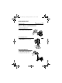
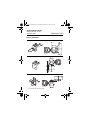
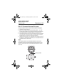
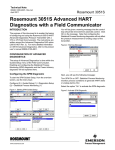
4593 Rev AB.fm Page 1 Thursday, September 21, 2006 3:12 PM
Quick Installation Guide
00825-0100-4593, Rev AB
September 2006
Rosemount 1151
Rosemount 1151 Smart
Pressure Transmitter
Start
Step 1: Mount the Transmitter
Step 2: Consider Housing Rotation
Step 3: Connect the Wiring and Power Up
Step 4: Set Switches
Step 5: Configuration
Step 6: Trim the Transmitter
Product Certifications
End
© 2006 Rosemount Inc. All rights reserved. All marks property of owner. Rosemount and the
Rosemount logotype are registered trademarks of Rosemount Inc.
HART®
¢00825-0100-4593X¤
www.rosemount.com
4593 Rev AB.fm Page 2 Thursday, September 21, 2006 3:12 PM
Quick Installation Guide
00825-0100-4593, Rev AB
September 2006
Rosemount 1151
Emerson Process Management
Rosemount Division
Emerson Process Management
GmbH & Co. OHG
8200 Market Boulevard
Chanhassen, MN USA 55317
T (US) (800) 999-9307
T (Intnl) (952) 906-8888
F (952) 949-7001
Shipping Address:
Argelsrieder Feld 3
82234 Wessling
Germany
T 49 (8153) 9390
F49 (8153) 939172
Emerson Process Management
Asia Pacific Private Limited
Beijing Rosemount Far East
Instrument Co., Limited
1 Pandan Crescent
Singapore 128461
T (65) 6777 8211
F (65) 6777 0947/65 6777 0743
No. 6 North Street,
Hepingli, Dong Cheng District
Beijing 100013, China
T (86) (10) 6428 2233
F (86) (10) 6422 8586
IMPORTANT NOTICE
This installation guide provides basic guidelines for Rosemount 1151
transmitters. It does not provide instructions for configuration, diagnostics,
maintenance, service, troubleshooting, Explosion-Proof, Flame-Proof, or
intrinsically safe (I.S.) installations. Refer to the Rosemount 1151 reference
manual (document number 00809-0100-4593) for more instruction.
This manual is also available electronically on www.rosemount.com.
WARNING
Explosions could result in death or serious injury:
Installation of this transmitter in an explosive environment must be in
accordance with the appropriate local, national, and international standards,
codes, and practices. Please review the approvals section of the 1151
reference manual for any restrictions associated with a safe installation.
• Before connecting a HART-based communicator in an explosive
atmosphere, make sure the instruments in the loop are installed in
accordance with intrinsically safe or non-incendive field wiring practices.
• In an Explosion-Proof/Flame-Proof installation, do not remove the
transmitter covers when power is applied to the unit.
Process leaks may cause harm or result in death.
• To avoid process leaks, only use the o-ring designed to seal with the
corresponding flange adapter.
Electrical shock can result in death or serious injury.
• Avoid contact with the leads and the terminals. High voltage that may be
present on leads can cause electrical shock.
4593 Rev AB.fm Page 3 Thursday, September 21, 2006 3:12 PM
Quick Installation Guide
00825-0100-4593, Rev AB
September 2006
Rosemount 1151
STEP 1: MOUNT THE TRANSMITTER
Liquid Flow Applications
1. Place taps to the side of the line.
2. Mount beside or below the taps.
Flow
Gas Flow Applications
1. Place taps in the top or
side of the line.
2. Mount beside or above the taps.
Flow
Steam Flow Applications
1. Place taps to the side of the line.
2. Mount beside or below the taps.
3. Fill impulse lines with water.
Flow
4593 Rev AB.fm Page 4 Thursday, September 21, 2006 3:12 PM
Quick Installation Guide
00825-0100-4593, Rev AB
September 2006
Rosemount 1151
STEP 1 CONTINUED...
Pipe Mount
Panel Mount(1)
Flat Mount
(1) Panel bolts are customer supplied.
4593 Rev AB.fm Page 5 Thursday, September 21, 2006 3:12 PM
Quick Installation Guide
00825-0100-4593, Rev AB
September 2006
Rosemount 1151
STEP 2: CONSIDER HOUSING ROTATION
To improve field access or to better view the optional LCD display:
1. Loosen the housing lock nut.
2. Rotate the housing clockwise to the desired position – up to 90°
from its original position. Over rotating will damage the transmitter.
3. If the desired position is attained, tighten the housing lock nut.
4. If the desired position cannot be reached because the housing will
not rotate further, rotate the housing counterclockwise until in the
desired position (up to 90° from its original position).
5. Tighten the housing lock nut to 420-in/lb. Use a sealing compound
(Loctite 222 – Small Screw Threadlocker) on the threads to ensure
a watertight seal on the housing.
NOTE
If the desired position cannot be attained within the 90° limit, the
transmitter will need to be disassembled. See the Rosemount 1151
reference manual (document number 00809-0100-4593) for further
instruction.
Housing Lock Nut
4593 Rev AB.fm Page 6 Thursday, September 21, 2006 3:12 PM
Quick Installation Guide
00825-0100-4593, Rev AB
September 2006
Rosemount 1151
STEP 3: CONNECT WIRING AND POWER UP
Use the following steps to wire the transmitter:
1. Remove the housing cover on the side marked TERMINALS on the
nameplate.
2. Connect the positive lead to the “+” terminal and the negative lead
to the “–” terminal.
NOTE
Do not connect the powered signal wiring to the test terminals. Power
could damage the test diode in the test connection. Twisted pair cable
should be used for best results. In high EMI/RFI environments, use
either transient terminal block or shielded signal wiring. Use 12 to 24
AWG wire and do not exceed 5,000 feet (1500 meters).
3. Plug and seal unused conduit connections.
4. If applicable, install wiring with a drip loop. Arrange the drip loop
so the bottom is lower than the conduit connections and the
transmitter housing.
Figure 1 shows wiring connections necessary to power a 1151 and
enable communications with a hand-held HART communicator. A
HART Interface may be connected at any termination point in the loop.
signal loop must have 250 ohms minimum load for communications.
Signal loop may be grounded at any point or left ungrounded
4593 Rev AB.fm Page 7 Thursday, September 21, 2006 3:12 PM
Quick Installation Guide
00825-0100-4593, Rev AB
September 2006
Rosemount 1151
Figure 1. Field Wiring Diagram
Power
Supply
Current
Meter
Optional
Indicator
RL ≥ 250 ⍀
4593 Rev AB.fm Page 8 Thursday, September 21, 2006 3:12 PM
Quick Installation Guide
00825-0100-4593, Rev AB
September 2006
Rosemount 1151
STEP 3 CONTINUED...
Power Supply
The dc power supply should provide power with less than two percent
ripple. The total resistance load is the sum of the resistance of the
signal leads and the load resistance of the controller, indicator, and
related pieces. Note that the resistance of intrinsic safety barriers, if
used, must be included.
Figure 2. Load Limitation
Rmax
RL
Operating
Region
Rmin
Vmin
Code
S(1)
Vmin
12
Vmax
45
Rmin
0
VS
Rmax
1650
Vmax
RL at Supply Voltage (VS)
RL = 43.5 (VS – 12)
(1) A minimum of 250 Ω is required for communication.
4593 Rev AB.fm Page 9 Thursday, September 21, 2006 3:12 PM
Quick Installation Guide
00825-0100-4593, Rev AB
September 2006
Rosemount 1151
STEP 4: SET THE SWITCHES
Failure Mode Alarm Switch
1. Remove the housing cover.
2. Locate the failure mode switch (see Figure 3).
3. Move the switch to the desired alarm setting. To set the failure
mode to high alarm, position the switch toward “HI.” To set the
failure mode to low alarm, position the switch to “LO.”
4. Replace the housing cover.
Write-Protect Switch
In the “ON” position, the write-protect switch prevents changes to the
configuration data.
1. Remove the housing cover.
2. Move the write-protect switch to the “OFF.”
3. Verify transmitter configuration (see “Verify Transmitter
Configuration”).
4. Move the write-protect switch to the “ON.”
5. Replace the housing cover.
Figure 3. Switch Locations
Write-Protection Switch
Failure Mode Switch
HI
Zero Adjustment
Buttons
4593 Rev AB.fm Page 10 Thursday, September 21, 2006 3:12 PM
Quick Installation Guide
00825-0100-4593, Rev AB
September 2006
Rosemount 1151
STEP 5: VERIFY CONFIGURATION
Verify Transmitter Configuration
NOTE:
A check (3) indicates the basic configuration parameters. At minimum,
these parameters should be verified as part of the configuration and
startup procedure.
Table 1. HART Communicator Fast Key Sequence
Function
Fast Key Sequences
Analog Output
3
Analog Output Alarm
1, 4, 3, 3
Burst Mode Control
1, 4, 3, 4, 3
Burst Operation
1, 4, 3, 4, 4
Calibration
1, 2, 3
Characterize
1, 4, 1, 1, 2, 2
✓ Damping
1, 3, 6
Date
1, 3, 4, 1
Descriptor
1, 3, 4, 2
Digital-to-Analog Trim (4–20 mA Output)
1, 2, 3, 2, 1
Field Device Information
1, 4, 4, 1
Full Trim
1, 2, 3, 3
Keypad Input
1, 2, 3, 1, 1
Loop Test
1, 2, 2
Lower Range Value
4, 1
Lower Sensor Trim
1, 2, 3, 3, 2
Message
1, 3, 4, 3
Meter Type
1, 3, 4, 5
Number of Requested Preambles
1, 4, 3, 4, 2
Percent Range
1, 1, 2
Poll Address
1, 4, 3, 4, 1
Pressure
2
✓ Range Values
1, 3, 3
Rerange
1, 2, 3, 1
Scaled D/A Trim (4–20 mA Output)
1, 2, 3, 2, 2
Self-Test (Transmitter)
1, 2, 1, 1
Sensor Information
1, 4, 4, 2
4593 Rev AB.fm Page 11 Thursday, September 21, 2006 3:12 PM
Quick Installation Guide
00825-0100-4593, Rev AB
September 2006
Sensor Trim Points
Status
✓ Tag
✓ Transfer Function (Setting Output Type)
Transmitter Security (Write Protect)
Trim Analog Output
✓ Units (Process Variable)
Upper Range Value
Upper Sensor Trim
Zero Trim
Rosemount 1151
1, 2, 3, 3, 4
1, 2, 1, 2
1, 3, 1
1, 3, 5
1, 3, 4, 4
1, 2, 3, 2
1, 3, 2
5, 2
1, 2, 3, 3, 3
1, 2, 3, 3, 1
Configure LCD Display
Figure 4. LCD Meter.
Digital Bar Graph
Left
Configuration
Button
Retaining Ring
Right
Configuration
Button
NOTE
The LCD display time-out is approximately 16 seconds. If keys are not
pressed within this period, the indicator reverts to reading the signal.
4593 Rev AB.fm Page 12 Thursday, September 21, 2006 3:12 PM
Quick Installation Guide
00825-0100-4593, Rev AB
September 2006
Rosemount 1151
STEP 5 CONTINUED...
Position the Decimal Point and Select the Meter Function
1. Unscrew the retaining ring shown in Figure 4 and remove the LCD
display cover.
2. Press the left and right configuration buttons simultaneously and
release immediately.
3. To move the decimal point to the desired location, press the left
configuration button. Note that the decimal point wraps around.
4. To scroll through the mode options, press the right configuration
button until the desired mode is displayed (see Table 2).
5. Press both configuration buttons simultaneously for two seconds.
6. Replace the LCD Display cover.
Table 2. LCD Display Modes
Options
Relationship between Input Signal and Digital Display
L in
Linear
L in F
Linear with five-second filter
Srt
Square root
SrtF
Square root with five-second filter
Square root function: relates to the digital display. The bar graph output
remains linear with the current signal.
Square root response: digital display will be proportional to the square root of
the input current where 4 mA=0 and 20 mA=1.0, scaled per the calibration
procedure. The transition point from linear to square root is at 25% of full scale
flow.
Filter response: operates upon “present input” and “input received in the
previous five second interval” in the following manner:
Display = (0.75 x previous input) + (0.25 x present input)
This relationship is maintained provided that the previous reading minus the
present reading is less than 25% of full scale.
NOTE
The meter displays “----” for approximately 7.5 seconds while the
information is being stored.
4593 Rev AB.fm Page 13 Thursday, September 21, 2006 3:12 PM
Quick Installation Guide
00825-0100-4593, Rev AB
September 2006
Rosemount 1151
STEP 5 CONTINUED...
Set the Display Equivalent to a 4 mA Signal
1. Unscrew the retaining ring shown in Figure 4 and remove the LCD
display cover.
2. Press the left button for two seconds.
3. To decrement the display numbers, press the left configuration
button and to increment the numbers, press the right configuration
button. Set the numbers between –999 and 1000.
4. To store the information, press both configuration buttons
simultaneously for two seconds.
5. Replace the LCD display cover.
Set the Display Equivalent to a 20 mA Signal
1. Unscrew the retaining ring shown in Figure 4 and remove the LCD
display cover.
2. Press the right button for two seconds.
3. To decrement the display numbers, press the left configuration
button on the display and to increment the numbers, press the right
configuration button. Set the numbers between –999 and 9999.
The sum of the 4 mA point and the span must not exceed 9999.
4. To store the information, press both configuration buttons
simultaneously for two seconds. The LCD display is now
configured.
5. Replace the LCD Display cover.
4593 Rev AB.fm Page 14 Thursday, September 21, 2006 3:12 PM
Quick Installation Guide
00825-0100-4593, Rev AB
September 2006
Rosemount 1151
STEP 6: TRIM THE TRANSMITTER
NOTE
Transmitters are shipped fully calibrated per request or by the factory
default of full scale (span = upper range limit).
Full Trim
A full trim is a two-point sensor calibration where two end-point
pressures are applied, and the transmitter process variable output is
adjusted to agree with the pressure input.
Using the HART Communicator
HART Fast Keys
1, 2, 3, 3
Steps
1. Equalize or vent the transmitter and connect HART
communicator.
2. At the menu, input the HART Fast Key sequence.
3. Follow the commands to perform a full trim.
Zero Trim
A zero trim is a single-point adjustment used for compensating
mounting position effects. When performing a zero trim, ensure that
the equalizing valve is open and all wet legs are filled to the correct
level. If zero offset is less than 3% of true zero, follow the “Using the
HART Communicator” instructions below. If zero offset is greater than
3% of true zero, follow the “Using the Transmitter Zero Adjustment
Buttons” instructions.
Using the HART Communicator
HART Fast Keys
1, 2, 3, 3, 1
Steps
1. Equalize or vent the transmitter and connect HART
communicator.
2. At the menu, input the HART Fast Key sequence.
3. Follow the commands to perform a zero trim.
4593 Rev AB.fm Page 15 Friday, September 22, 2006 9:16 AM
Quick Installation Guide
00825-0100-4593, Rev AB
September 2006
Rosemount 1151
STEP 6 CONTINUED...
Using the Transmitter Zero Adjustment Buttons
Perform the following steps to perform a rerange using the zero
adjustment buttons (see Figure 3).
1. Apply a pressure equivalent to the lower calibrated value on the
high side of the transmitter.
2. Remove the circuit side cover to expose the span and zero
buttons. Hold both the span and zero buttons down simultaneously
for at least five seconds to activate the controls.
3. Press the zero button for five seconds to set the 4 mA point. Verify
that the output is 4 mA.
4. Apply a pressure equivalent to the higher calibrated value to the
high side of the transmitter.
5. Press the span button for five seconds to set the 20 mA point.
Verify that the output is 20 mA.
4-20 mA Output Trim
A 4-20 mA output trim adjusts the transmitter milliampere output to
match plant standards. This procedure is used to trim the transmitter
using a current meter.
Using the HART Communicator
HART Fast Keys
1, 2, 3, 2, 2
Steps
1. Equalize or vent the transmitter and connect HART
communicator.
2. At the menu, input the HART Fast Key sequence.
3. Follow the commands to perform a full trim.
4593 Rev AB.fm Page 16 Thursday, September 21, 2006 3:12 PM
Quick Installation Guide
00825-0100-4593, Rev AB
September 2006
Rosemount 1151
PRODUCT CERTIFICATIONS
Approved Manufacturing Locations
Rosemount Inc. — Chanhassen, Minnesota, USA
Fisher-Rosemount GmbH & Co. — Wessling, Germany
Emerson Process Management Asia Pacific
Private Limited — Singapore
Beijing Rosemount Far East Instrument Co., Limited – Beijing, China
European Directive Information
The EC declaration of conformity for all applicable European directives
for this product can be found on the Rosemount website at
www.rosemount.com. A hard copy may be obtained by contacting our
local sales office.
ATEX Directive (94/9/EC)
Emerson Process Management complies with the ATEX Directive.
European Pressure Equipment Directive (PED) (97/23/EC)
1151GP9, 0; 1151HP4, 5, 6, 7, 8 Pressure Transmitters
— QS Certificate of Assessment - EC No. PED-H-20
Module H Conformity Assessment
All other 1151 Pressure Transmitters
— Sound Engineering Practice
Transmitter Attachments:
Diaphragm Seal - Process Flange - Manifold
— Sound Engineering Practice
Electro Magnetic Compatibility (EMC) (89/336/EEC)
All models
— EN 50081-1: 1992; EN 50082-2:1995;
EN 61326-1:1997 – Industrial
4593 Rev AB.fm Page 17 Thursday, September 21, 2006 3:12 PM
Quick Installation Guide
00825-0100-4593, Rev AB
September 2006
Rosemount 1151
Hazardous Locations Certifications
North American Certifications
Factory Mutual (FM) Approvals
FM Explosion Proof tag is standard. Appropriate tag will be substituted
if optional certification is selected.
I5
Explosion Proof: Class I, Division 1, Groups B, C, and D.
Dust-Ignition Proof: Class II, Division 1, Groups E, F, and G;
Class III, Division 1. Indoor and outdoor use. NEMA 4X. Factory
Sealed.
Intrinsically safe for Class I, II, and III Division 1, Groups A, B, C,
D, E, F, and G hazardous locations in accordance with entity
requirements and Control drawing 01151-0214 and 00268-0031.
Non- incendive for Class I, Division 2, Groups A, B, C and D
hazardous locations.
For entity parameters see control drawing 01151-0214.
Canadian Standards Association (CSA) Approvals
E6 Explosion proof for Class I, Division 1, Groups C and D; Class II,
Division 1, Groups E, F, and G; Class III, Division 1 Hazardous
Locations. Suitable for Class I, Division 2, Groups A, B, C, and D;
CSA enclosure type 4X. Factory Sealed.
I6
Intrinsically safe for Class I, Division 1, Groups A, B, C, and D
hazardous locations when connected per Drawing 01151-2575.
For entity parameters see control drawing 01151-2575.
Temperature Code T2D.
4593 Rev AB.fm Page 18 Thursday, September 21, 2006 3:12 PM
Quick Installation Guide
00825-0100-4593, Rev AB
September 2006
Rosemount 1151
European Certifications
E8
ATEX Flameproof
Certification Number CESI03ATEX037
ATEX Marking
II 1/2 G
EEx d IIC T6 (–40 ≤ Ta ≤ 40 °C)
EEx d IIC T4 (–40 ≤ Ta ≤ 80 °C)
1180
V = 60 Vdc maximum
ATEX Intrinsic Safety Certification
I1 Certification Number BAS99ATEX1294X
ATEX Marking
II 1 GD
EEx ia IIC T5 (–60 ≤ Ta ≤ 40 °C)
EEx ia IIC T4 (–60 ≤ Ta ≤ 80 °C)
Dust Rating: T90 °C (Ta = –20 to 40 °C)
IP66
1180
Entity Parameters
Ui = 30V
Ii = 125 mA
Pi = 1.0 W (T4) or 0.67 W (T5)
Ci = 0.034 µF
Li = 20 µH
Special Conditions for safe use (x):
The apparatus is not capable of withstanding the 500V insulation
test required by EN50020:1994. This must be taken into account
when installing the apparatus.
4593 Rev AB.fm Page 19 Thursday, September 21, 2006 3:12 PM
Quick Installation Guide
00825-0100-4593, Rev AB
September 2006
Rosemount 1151
ATEX Type N and Dust Certification
N1 Certificate Number: BAS99ATEX3293X
ATEX Marking:
II 3 GD
EEx nL IIC T5 (-40 ≤ Ta ≤ 40 °C)
EEX nL IIC T4 (-40 ≤ Ta ≤ 80 °C)
Dust Rating: T90 °C (Ta = -20 to 40 °C)
Ui = 45 Vdc maximum
IP66
Special Conditions for safe use (x):
The apparatus is not capable of withstanding the 500V insulation
test required by EN 50021:1999. This must be taken into account
when installing the apparatus.
Australian Certifications
Standards Association of Australia (SAA) Certification
E7 Flameproof
Certificate Number Ex 494X
Ex d IIB + H2 T6
DIP T6 IP65
Special Conditions for safe use (x):
For transmitters having NPT, PG or G cable entry threads, an
appropriate flameproof thread adaptor shall be used to facilitate
application of certified flameproof cable glands or conduit system.
4593 Rev AB.fm Page 20 Thursday, September 21, 2006 3:12 PM
Quick Installation Guide
00825-0100-4593, Rev AB
September 2006
I7
Rosemount 1151
Intrinsically Safe
Certificate Number: Ex 122X
Ex ia IIC T5 (Tamb = 40 °C)
Ex ia IIC T4 (Tamb = 80 °C)
Special Conditions for Safe Use (x):
The equipment has been assessed to the entity concept and
accordingly the following electrical parameters must be taken into
account during installation.
Table 3. Entity Parameters
Ui = 30V
Ii = 125 mA
Pi = 1.0 W (T4) or 0.67W (T5)
Ci = 14.8 nF
Li = 20 µH
N7 Type N
Certificate Number: Ex 887X
Ex n IIC T6 (Tamb = 40 °C)
Ex n IIC T5 (Tamb = 80 °C)
Special Conditions for safe use (x):
The equipment must be connected to a supply voltage which
does not exceed the rated voltage. The enclosure end caps must
be correctly fitted whilst the equipment is energized.
Combination Certifications
Stainless steel certification tag is provided when optional approval is
specified. Once a device labeled with multiple approval types is
installed, it should not be reinstalled using any other approval types.
Permanently mark the approval label to distinguish it from unused
approval types.
C6 Combination of I6 and E6, CSA Explosion Proof and Intrinsic Safety
Approval. Factory Sealed.
K5 Combination of Explosion Proof, Intrinsic Safety, and
Non-incendive Approvals.