1
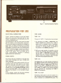
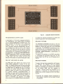
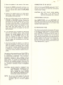
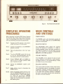
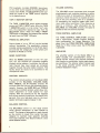
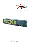
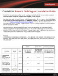
-iin
Model 2252
Stereop hon ic
Receiver
MARANTZ CO., INC. 20525 NORDHOFF STREET, CHATSWORTH, CALIFORNIA 91311
A WHOLLY-OWNED SUBSIDIARY OF SUPERSCOPE INC., CHATSWORTH, CALIFORNIA 91311
FOREWORD
GENERAL
For optimum performance and enjoyment from
your Model 2252 Stereo Receiver, please study
these instructions carefully.
Installation and
operation are not complicated, but its flexibility
and features deserve your becoming familiar with
its controls and connections.
This manual is divided into two parts. The first
covers installation and operation in simple, nontechnical language. The second describes the 2252
in more detail with technical specifications and
functional explanations.
For quick identification of the controls and connections, references to them are printed in BOLDFACE TYPE, exactly as they appear on the front
and rear panels of your Receiver.
The Marantz Model 2252 is an all solid state
receiver incorporating the innovative design and
unparalleled technology that have made Marantz
famous in the audio component industry.
The Model 2252 features a sensitive stereo FM
tuner, a highly selective AM tuner, and a low distortion preamplifier and amplifier on a single
chassis. The FM tuner features a front end which
employs a dual gate MOSFET and FM I F unit, a
phase locked loop multiplex decoder and an AM
tuner, all of which utilize IC's throughout. The
amplifier sections permit the connection of two
stereo pairs of loud-speakers, a turntable or
record changer, two tape recorders, stereo headphones, and an auxiliary source such as an additional tuner or a TV sound source.
AFTER
AC Line Operation
WARNING:
TO PREVENT
FIRE OR SHOCK HAZARO,
NOT EXPOSE THIS APPLIANCE
TO RAIN
00
OR MOISTURE.
DESCRIPTION
UNPACKING
It is advisable to retain all original packing material to prevent damage should you wish to transport or ship the Model 2252 (refer to page 14 for
repacking and shipping instructions). Be careful
that you do not inadvertently throwaway or lose
the parts packed with the unit.
Please inspect your Model 2252 carefully for any
signs of shipping damage. Our very strict quality
control and professional pride ensure that each
Model 2252 left the factory in perfect condition.
If the unit is damaged or fails to operate, immediately notify your dealer. If the unit was shipped
to you directly, notify the transportation company without delay. Only you, the consignee,
may institute a claim against the carrier for shipping damage. Save the carton and all packing
material as evidence of damage for their inspection. Should assistance be required, the Marantz
Company will cooperate fully in assisting your
claim.
Please fill out and mail the Warranty Registration
Card within ten days of purchase. The card will
remain on file at the Marantz Company for the
duration of the warranty period. We also strongly
advise that you retain your sales receipt to provide proof of purchase in the event that warranty
service is sought.
Maintenance
Volume
Control
General
Fuse
Replacement
Cleaning
FM
Fron
End
Control
Mono
Functions
Circuits
Speaker
Service
In Case
Notes
Phasing
of
Difficulty
Stereo
Demodulator
General
Selector
AM
Tuner
Specifications
Switch
Tape
Recording
and Dubbing
11
2
6114
8
4
1
5
14
651 11
8
71
2
69753
Amplifier
Repacking
for Shipment
Recording
Dolbyized
Technical
Dubbing
Description
Tape
Monitor
SwitchFM Programs
Muting
Repairs
Circuit
Phono
EO
Amplifier
FM IF1 Amplifier
CONTENTS
TABLE
OF
liST OF IllUSTRATIONS
1.
2.
3.
4.
5.
6.
7.
8.
Rear Panel Connection Facilities
AM/FM Antenna Connection
AM Ferrite-rod Antenna
Loudspeaker System Connections
Front Panel Controls and Jack
Stereophone Plug
Functional Block Diagram
Packing Instructions
1
2
2
3
5
6
10
14
,
~-l
Figure 1.
Rear Panel Connection Facilities
PREPARATION FOR USE
REAR PANEL CONNECTIONS
TAPE JACKS
Figure 1 shows the location of input and output
jacks on the rear panel. These jacks are for "permanent" connections. Front panel jacks and their
use will be discussed later.
All connections to the rear panel should be made
with the power to the entire system turned off.
The rear panel signal connections are arranged in
stereo pairs. All signal connections to the Model
2252, with the exception of the FM antenna and
loudspeakers, should be made with shielded audio
cables. To avoid confusion, connect one cable at
a time between the 2252 and the other components of your system. This is the safest way to
avoid cross-connecting channels or confusing
signal sources with destinations.
TAPE
PHONO INPUTS
The phono jacks are intended for use with magnetic phono cartridges and have a 47,000 ohm
input impedance.
If a hum is heard when playing records, this is an
indication that the record player or its connections are incorrectly grounded. Connect a separate ground wire from the turntable or record
changer from to the CHASSIS GROUND binding
post of the Model 2252. If this is ineffective, try
reversing the polarity of the turntable's power
plug.
If hum persists, consult the instruction booklets
for the turntable and/or phono cartridge.
1
IN
The pair of TAPE 1 IN jacks serve two purposes:
1. By depressing the TAPE 1 MONITOR pushswitch, signals can be played from a tape recorder set for playback mode of operation.
This permits playing the tape source stereophonically or monophonically as indicated by
the position of the MONO pushswitch.
2. While your tape recorder is recording, you can
monitor the resulting tape quality by depressing the TAPE 1 MONITOR pushswitch. This
requires that your recorder be equipped with
separate record and playback heads and separate record and playback electronics.
TAPE 2 IN
The signals from your tape recorder connected to
the TAPE 2 I N jacks can be played back when the
SELECTOR switch is placed in the TAPE 2 position and the TAPE 1 MONITOR switch is released. In addition, these jacks allow tape copying
from TAPE 2 to TAPE 1. The resulting recording
can be monitored by depressing the TAPE 1
MONITOR pushswitch.
TAPE 1 & 2 OUT
Connecting these jacks to the line inputs of a
tape recorder permits recording from the program
source indicated by the SELECTOR switch. The
75·ohm
coaxial cable
without
"F" connector
"'i"d1
Figure 2.
AM/FM Antenna
Connection
signals available at this pair of jacks are not
affected by the BALANCE, VOLUME, TREBLE,
BASS,
HI FILTER, LOUDNESS, and MONO
pushswitches on the front panel.
AUX INPUTS
The AUX INPUT jacks are for miscellaneous high
level signal sources such as additional tuners
and/or receivers, tape players, phonographs that
provide RIAA equalized high level output, TV
sound outputs and other external components.
FM ANTENNA
The best FM reception is obtained with a LogPeriodic type antenna mounted on a good quality
rotor system. For fringe areas, Marantz recommends a Log-Periodic antenna with six or more
elements designed expressly for FM reception.
To minimize local noise and multipath picked up
by the lead-in wires, use a balanced and shielded
300 ohm cable or a coaxial 75 ohm cable with a
300 to 75 ohm matching transformer at the
antenna. Unshielded lead-in acts as an omnidirectional antenna, and can cancel the directional benefits of your antenna. Low-loss 300
ohm shielded cable consists of two inner conductors plus an outer shield and insulating jacket.
This type of shielded cable effectively prevents
the lead-in from contributing multipath distortion.
For rural areas, it is recommended that a local
dealer be consulted about antenna installation
and lightning arrestor protection. Master antenna
systems are not recommended for use with your.
Figure 3.
AM Ferrite-rod
Antenna
Model 2252; such systems are usually designed
expressly for television reception and frequently
suppress FM signals before distribution. In addition, master antenna systems often severely reduce the quality of the FM signal. Where outdoor
antennas are prohibited or inconvenient, place the
antenna in vacant attic space or use a simple 300
ohm TV "rabbit ear" antenna or the ribbon-type
folded dipole antenna supplied with the Model
2252. Both are practical and will give satisfactory
results in primary signal areas.
Figure 2 shows connection methods for various
antennas. If 75-ohm cable is desired, we recommend using the type with an "F"-type connector
terminal attached to the cable. This is the easiest
type of cable to connect and disconnect.
AM ANTENNA
Your Tuner is equipped with an AM ferrite-rod
antenna. BEFORE USING THE MODEL 2252,
SWING THE ANTENNA OUT AS SHOWN IN
FIGURE 3.
The ferrite-rod antenna will give you satisfactory
results in primary signal areas. However, an outdoor antenna will provide better reception in
weaker signal areas. Three single wires are required
to make an AM outdoor antenna. First, connect
one end of a single wire to the AM ANTENNA
terminal on the rear panel, and the other end to a
very high horizontal antenna wire of 25 to 75 feet
in length suspended between insulators in an outdoor location (the higher the better). Next, connect the third single wire between the "G"
terminal of your Model 2252 and an authenticated earth ground (such as a metal water pipe).
2
- ---c
SPEAKER
LEFT
n
]1-' III I
1
rl
SPEAKER SYSTEMS·
. SYSTEM 1
J 111 J ·1]
r1l1T
--::....-:-~.
1
+
lTTI
]'1fll!
SYSTEM
ltjldJ ldJ ldJ
j
TTJ n
IIU· r~I··~
r
r -I!]
I1I:r
ILLllrili ~
LIT
---
~~R~~L~~
SYSTEM
RIGHT
ITIH
.~._--::---_~.
2
- -
~~l6JlaJ[BJ
ffi
+
SPEAKER
SYSTEM
2
Figure 4.
FM QUADRADIAL
OUTPUT JACK
Loudspeaker System Connections
Iy breaks the internal connections to prevent the
external equipment from being bypassed.
In anticipation of future four channel quadraphonic broadcasting, your Model 2252 is equipped
with an FM QUADRADIAL OUTPUT jack. The
signal available at this jack is the unequalized
buffered output of the FM discriminator. Its
level, frequency response characteristics, and output impedance are ideal to drive a four channel
adaptor. This jack can also be used as a simple
"white noise" generator for checking the response
characteristics of loudspeakers of amplifiers. For
this application, connect the FM QUADRADIAL
OUTPUT jack to the TAPE 1 input jack, pressthe
TAPE 1 MONITOR switch, place the Model 2252
in FM mode with the muting off and tune
between FM stations to receive interstation noise.
The SPEAKER SYSTEMS terminals on the rear
panel can accommodate two stereo pairs of loudspeakers. Connect the main pair to the SYSTEM
1 terminals. The SYSTEM 2 terminals are for a
second stereo pair of loudspeakers (see Figure 4).
Selection of loudspeaker systems is made with the
SYSTEM 1-SPKR-SYSTEM 2 pushswitches on
the front panel.
To connect the speakers to the 2252, use ordinary #18 gauge two conductor lamp cord. For distances longer than 30 feet, use #16 gauge wire or
heavier.
PRE OUT AND MAIN IN JACKS
SPEAKER PHASING
The PRE OUT jacks deliver the output of the
Model 2252 preamplifier circuits to the rear
panel. The MAIN IN jacks are the input terminals
of the power amplifier section of the Model 2252.
The PRE OUT and MAIN IN jacks are bridged
internally by special contacts within the jack
assembly. When you wish to use such equipment
as a graphic equalizer, compressor/limiter, or
expander, you may connect these instruments to
your Model 2252 with appropriate lengths of
shielded audio cables. When the external equipment is connected, the insertion of its RCA
phono plugs in to the MAIN IN jacks automatical-
To assure the best stereo separation and frequency response, the speakers must be properly
phased. The positive terminal on each speaker
should be connected to its respective (+) terminal
on the Model 2252, and the negative or
"common" terminal should be connected to its
respective (-) terminal. To verify that a pair of
speakers are correctly phased, perform the following test:
3
SPEAKE R SYSTEMS
1. Complete the necessary signal connections so
that program material may be played through
the speakers.
2. Place the speakers in the center
of the room.
3. Depress the MONO pushswitch and playa record (or radio or tape) with strong bass tones
at a low volume level. Center the BALANCE
control.
CONNECTION
With the front panel POWER pushswitch "OUT",
plug the line cord into an electrical outlet supplying the proper voltage.
CAUTION:
4. Position the speakers about six inches apart,
face-to-face. Listen, particularly
to the apparent loudness of the bass tones.
DO NOT PLUG YOUR
MODEL
2252 INTO A DC OUTLET,
AS
SERIOUS DAMAGE WI LL OCCUR.
CONVENIENCE
5. Next, turn off all power, but do not disturb the
VOLUME
or BALANCE
settings. Reverse the
connections on the right speaker only. Turn on
the power and listen again. If the bass tones
now seem louder than in (3), you have corrected the phasing between the speakers. If the
bass notes now sound softer, turn off the
power and reconnect the speakers as they had
been originally.
6. If an additional
pair of speakers is used along
with the main speaker system, check phasing
between the remote speakers and the main
speakers. Use the BALANCE
control to play
only two speakers at once, and invert the
wiring on the remote speakers as necessary.
Do not change the connections on the main
speaker system.
TO AC OUTLET
One
OUTLETS
UNSWITCHED
and
one SWITCHED
AC
OUTLET are provided on the rear panel for powering associated components of your system (tape
recorder, record player, etc.).
AC PROTECTOR
FUSE
This feature automatically
disconnects AC power
in the event of a power source or circuit overload.
If the POWER pushswitch is activated and the
front panel fails to illuminate
and no sound is
heard through the speakers, turn off the power
and unscrew the fuse holder on the rear panel and
visually inspect the fuse to see if the internal conducting filament
has opened. If so, replace the
fuse with one having the same specifications. See
"Fuse Replacement", page 11.
7. Once having phased all speakers, you need not
repeat this procedure in the future if you now
mark the speaker connections
and/or cables.
Any method of coding is satisfactory, provided
it enables you, in the future, to duplicate your
now-correct hookup b~tween speakers and amplifier.
Use caution when connecting
your Model 2252 to
~ 'an
a loudspeaker
built-in powerThesupply
such as
electrostatic with loudspeaker.
"common"
connection
terminal
of such a speaker may' be
capacitively
coupled to ground through its own
power supply. To protect the Model 2252 from
distortion
and possible overload, make sure the
(-) terminals of the Model 2252 are connected to
the "common"
terminals of such a loudspeaker
system.
CAUTION:
NOTE:
NEVER DIRECTLY
CONNECT THE
LOUDSPEAKER
TERMINALS
OF
ONE
CHANNEL
IN PARALLEL
WITH
THOSE OF ANY
OTHER.
ANY RESULTING DAMAGE IS NOT
COVERED UNDER WARRANTY.
Do not use 4 ohm speakers if main and
remote speakers are to be uSed simu 1taneously.
Use 8 or 16 ohm speakers
only.
4
---..--_.~
FM 26~S
,_Lalanc:e-R
TAPE; t
MONITOR
LOUDNESS
FM
MUTIP«3
,..-SPKR--.
SYSTEM 1 SVSTEM:2
•
..
e
selector
bass
I'nid
treble
Figure 5.
.•olurne
MAIN CONTROLS
AND SWITCHES
When operating the Model 2252 Stereo Receiver
for the first time, follow these simple directions.
Later, full advantage can be taken of its versatility
with the remaining controls and pushswitches.
POWER SWITCH
Step 2. Connect the speakers to the SYSTEM 1
speaker terminals.
Step 3. Place all pushswitches in the "out"
tion.
posi-
Step 4. Turn the VOLUME control all the way
to the left (counterclockwise) and set
the balance control in center position.
Step 5.
Rotate TREBLE, MID and BASS controls to the 12 o'clock position (each
pair of pointers to dot).
Step 6.
Depress the SYSTEM 1 speaker pushswitch.
Step 7. Apply system power by depressing the
POWER switch.
Step 8. Select the desired program source by setting the SELECTOR switch to the appropriate position. If FM or AM is selected, rotate the Gyro-Touch TUNING
knob until the desired station is tuned.
Adjust the volume control to a comfortable
listening level.
5
e
Front Panel Controls and Jack
SIMPLIFIED OPERATING
PROCEDURES
Step 1. Connect the FM antenna to the appropriate terminals on the rear panel.
-po",~r
The POWER switch, when depressed, supplies AC
power to the Model 2252 and to the SWITCHED
outlet on its rear panel.
SELECTOR SWITCH
The SELECTOR switch selects the program
source for listening or recording. If a tape recorder's playback output has been connected to
the TAPE 2 IN jacks on the rear panel, you can
select tape listening by rotating the SELECTOR
SWITCH to the TAPE 2 position.
VOLUME CONTROL
The VOLUME control adjusts the level of both
output channels simultaneously while maintaining stereo balance at all normal settings. It does
not effect the record ing outputs.
BALANCE CONTROL
This control alters the level of either output channel in situations where it is necessary to correct
unbalanced programs sometimes encountered in
older stereo recordings or in stereo broadcasts. As
it is moved from its center position, it decreases
the level in one output channel while maintaining
the level in the other channel.
BASS, MID AND TREBEL CONTROLS
FM-25/lS SWITCH
These controls are used to adjust the tonal balance of program material to suit individual listening preference.
The Model 2252 is equipped with two meters, a
SIGNAL STRENGTH Meter and a TUNING
Meter.
To listen to a Dolbyized FM broadcast, connect a
Dolby noise reduction adaptor between the TAPE
lOUT
and IN jacks on the rear panel of the
Model 2252. Depress the FM-25/lS pushswitch,
and depress the TAPE 1 MONITOR switch. With
the FM-25/lS switch in, the audio output signals
an~ preset internally to standard Dolby level, and
the de-emphasis time constant applied to the
signals is also switched to 25/lsec automatically.
1. The SIGNAL STRENGTH Meter indicates the
signal strength of any AM or FM broadcast.
SYSTEM l-SPKR-SYSTEM 2 SWITCHES
TUNING
METER
2. The TUNING Meter operates on FM only and
indicates correct center tuning of the station.
GYRO-TOUCH TUNING
CONTROL
AM
Switch the SELECTOR to AM and tune to the
desired station. Then rotate the GYRO-TOUCH
TUNING knob slightly back and forth until the
maximum reading is obtained on the SIGNAL
STRENGTH Meter. The TUNING Meter is not
used for AM.
FM
These switches select the loudspeaker terminals
to which audio power is fed. Either the SYSTEM
1 or the SYSTEM 2 stereo pair of loudspeakers
may be operated individually, or simultaneously
if both switches are depressed. When the two
SYSTEM l-SPKR-SYSTEM 2 switches are in the
normal "out" position, all loudspeaker terminals
are internally disconnected from the power amplifier section. The signal at the headphones jack is
not affected by the SYSTEM l-SPKR-SYSTEM 2
switches. The "out"
position allows "private
listening" when stereo headphones are used.
NOTE: Volume level should be reduced to
minimum when switching speakers.
PHONES JACK
Switch the SELECTOR to FM and tune to the
desired station. Then slowly rotate the GYROTOUCH TUNING knob back and forth until
maximum reading is obtained on the SIGNAL
STRENGTH· Meter and the TUNING Meter
points to the center scale position. The multiplex
section of the Model 2252 is equipped with electronically triggered circuits which mute interstation noise and automatically switch to the
proper mode of operation for stereo and monophonic FM broadcasts. In addition, the STEREO
indicator light automatically indicates a stereo
broadcast.
This jack accepts headphones utilizing a standard
three conductor phone plug (see Figure 6). It is
internally connected to the power amplifier section through isolation resistors to provide adequate sound level with popular low impedance
headphones as well as with high impedance units.
Two or more sets of headphones may be used
with the aid of "Y" connectors. However, output
level will drop as additional headphones are
added. The headphone jack output is not affected
by the SYSTEM l-SPKR-SYSTEM 2 switches.
FM MUTING SWITCH
LEFT
When tuning to FM broadcasts with the MUTING
switch in its "in" position, the muting circuit will
eliminate interstation noise. To prevent muting
very weak stations along with the noise, the
muting action may be switched off by releasing
the MUTING pushswitch.
CHANNEL
LOUDNESS SWITCH
COMMON
RIGHT
CHANNEL
Figure 6.
Stereophone
Plug
The LOUDNESS switch compensates for human
hearing characteristics by boosting the bass and
treble response at low volume levels to achieve a
more pleasing tonal balance.
6
HI FILTER SWITCH
TAPE RECORDING
This switch can be used to reduce high frequency
noise such as that associated with the playing of
poorly recorded tapes or worn disc recordings.
When the AM tuner is being used, this switch will
help to suppress considerably the high pitched
"whistle" caused by adjacent AM channel interference. This filter will also, along with high frequency noise, slightly attenuate high frequency
program material, and should therefore be used
judiciously.
AND DUBBING
MONO SWITCH
When a marginal stereo signal is received, random
noise and phase modualtion may cause the tuner's
multiplex circuitry to trigger the STEREO mode
intermittently. In this case, it is sometimes desirable to cancel the multiplex operation entirely in
favor of obtaining a more listenable signal. The
MONO switch performs this function and converts all output signals to the MONOPHONIC
mode.
While playing a single channel source such as TV
or AM, depress the MONO pushswitch to hear the
source through both speakers. When playing a
monophone phonograph record, use this pushswitch to suppress rumble, record surface noise,
and pinch effect distortion.
TAPE 1 MONITOR SWITCH
When this pushswitch is "out", the program being
recorded and heard is determined by the setting
of the SELECTOR switch. With the TAP~ 1
MONITOR pushswitch "in", the amplifier input
connections are switched to the output of the
tape recorder without affecting the signal presented to the tape recorder's input, thus allowing
you to listen to the signal being recorded before
and after recording. This switch is also known as
the TAPE-SOURCE switch.
7
RECORDING
The program source selected by the SELECTOR
switch may be recorded on to either tape recorder. When the SE LECTOR is set to TAPE 2, however, the TAPE 2 OUT JACKS are muted to prevent feedback oscillations that would occur if
tape recorder 2 were inadvertently placed in the
record mode.
DUBBING
A tape played on tape recorder 2 may be copied
on to tape recorder 1. Set the SELECTOR switch
to TAPE 2. To monitor tape 1 as it is being recorded, depress the TAPE 1 MONITOR switch.
To monitor the source (which is, in this case, tape
2), releaseTAPE 1 MONITOR switch. Either tape
or source can be monitored without disturbing
the actual recording process.
RECORDING DOLBYIZED
FM PROGRAMS
Dolbyized FM broadcasts contain Dolbyized
audio information to which a special pre-emphasis
is applied for the purpose of improving the noise
reduction process. To make a Dolbyized tape recording of such broadcast, depress the FM-25pS
switch to properly de-emphasize the signal, but
bypass the noise reduction adaptor to record the
Dolbyized audio directly onto the tape. This can
be done by switching the Noise Reduction switch
to "OFF" if the Dolby adaptor is so equipped, or
by connecting the TAPE OUT jacks of the 2252
directly to the LINE IN jacks of the tape deck.
The inputs to the tape recorder in this application
must be properly calibrated beforehand according
to the procedure detailed in the Dolby unit's instruction booklet. To achieve proper calibration,
it is necessary that the record level control on the
Dolby unit be adjusted to the proper Dolby level
by use of the reference tone transmitted by the
FM station.
For monitoring purposes, connect the Dolby unit
between the line outputs of the tape recorder and
the TAPE IN jacks on the 2252.
When using a tape recorder containing a built-in
FM-25pS de-emphasis circuit, a better signal-tonoise ratio can be achieved by using only the
FM-25pS circuit in the Model 2252 instead of
the facilities in the tape recorder. Do not use both
de-emphasis circuits simultaneously.
TECHNICAL
DESCRIPTION
GENERAL
Figure 7 is a block diagram of the Model 2252
Receiver showing the main functional elements
and input and output signal routing. For clarity,
only the left audio channel is shown; the right
audio channel is identical. The MONO switch is
common to both channels. All audio controls are
ganged to their counterparts in the right channel.
FM FRONT END
FM antenna signals are applied through the antenna coil to the dual gate MOSF ET RF amplifier. The signals from the RF amplifier are fed
through the tuned RF tank circuit to the mixer
stage where the carrier frequency is converted to
the 10.7 MHz intermediate frequency. It is then
fed to the input of the I F amplifier.
Careful attention to the thermal and electrical
characteristics of the local oscillator has minimized drift, thus eliminating the necessity for
AFC.
FM IF AMPLIFIER
The FM IF amplifier system is composed of one
IC expressly developed for FM I F use, plus one
transistor and three dual-element ceramic filters.
The IC includes a complete I F amplifier, limiter
stages, FM discriminator, and a 6-stage double
ended type differential amplifier providing excellent AM rejection.
The FM discriminator stage is composed of a
Double balanced type quadrature detector circuit.
The signal from the front end is fed to the IC
through the 3 ceramic filters and the one transistor amplifier.
The characteristics of these filters are ideal in that
the 200 kHz passband is phase linear, with sharp
cutoff slopes. Its exceptional phase linearity assures the elimination of a major source of high
frequency distortion and a loss of stereo separation. The sharp cutoff slopes provide outstanding
selectivity, permitting reception of closely space
stations.
FM STEREO DEMODULATOR
The stereo composite signal obtained from the
quadrature detector is fed to the MPX IC. The L
and R signal outputs from the MPX IC are applied
through the low-pass filter and the de-emphasis
circuit to the one (per channel) transistor ampli-
fier. The output (about 1100 mV) obtained from
this amplifier is fed to the Land R output terminals at the rear panel through the function
switch.
This stereo demodulating IC employs a PLL
(Phase Locked Loop) technique, whereby the
phase of the 38 kHz switching carrier signal in the
decoder is constantly interlocked with the phase
of the 19 kHz input pilot signal. Phaseshift of the
switching carrier (38 kHz) is thereby eliminated
and deterioration of separation and distortion
does not occur.
19 kHz and 38 kHz muting circuits are not employed so that stability is greatly improved. Muting distortion, as a result of element aging or
adjacent temperature changes, is consequently
eliminated.
The stereo demodulating 38 kHz carrier switching
signal is very clean with no even harmonic content. SCA rejection of approximately 80 dB is
obtained since resonant beats are not generated
between the secondary harmonic (76 kHz) of the
38 kHz carrier switching signal and the SCA signal
(67 ± 7 kHz).
MUTING CIRCUIT
If there are no signals present, any FM tuner will
generate some noise. The muting circuit eliminates this noise. In addition, spurious noise that is
generated while tuning is also removed. The muting circuit in the Model 2252 is integrated" into
the I F stage. The circuit is also designed to minimize popping noises which tend to be generated
when muting is switched in and out.
AM TUNER
The AM tuner section of the Model 2252 is composed of an IC (incorporating an RF amplifier,
local oscillator, mixer, I F amplifier, and detector)
and a one transistor audio amplifier which amplifies the detected audio signals. A two section
variable capacitor is used to tune the antenna and
mixer stages. The ceramic filters utilized in the
AM I F amplifier are designed for high selectivity
and wide bandwidth for interference-free high
quality AM reception. Following the AM IF
amplifier, the AM detector recovers the audio
modulation and presents this signa! to the audio
amplifying stage and the mode selector switch.
The AM tuner and I F amplifier are subjected to
the action of an effective automatic gain control
circuit which maintains a constant volume level
for all stations in the AM band.
SELECTOR SWITCH
The Model 2252 has the capability to operate
from a variety of program sources, such as AM or
8
FM broadcasts, turntable (PHONO), tape player,
or any other source capable of providing 200 mV
output level (AUX). The SELECTOR switch connects the inputs of the TONE control amplifier
to the desired source.
TAPE 1 MONITOR SWITCH
The TAPE 1 MONITOR switch selects between
source and TAPE 1 INPUT jacks. When the TAPE
1 MONITOR switch is in its normal "out" position, the preamplifier receives its input from the
SELECTOR switch. When the TAPE 1 MONITOR switch is depressed, the preamplifier receives
its input from the TAPE 1 I N jacks.
PHONE EO AMPLIFIER
Phono signals of up to 100 mV can be hand led
without overloading. The equalization network
provides precise equalization to the RIAA standard and sets the voltage gain of the phono preamplifier to 40 dB (at 1 kHz).
MONO FUNCTIONS.
When the MONO pushswitch is in the "in" position, the two channels are connected together
through mixing resistors. In addition, the left and
right channel tape input signals are connected
together through the same resistor network. This
facility allows all inputs to be converted to the
monophonic mode.
CONTROL CIRCUITS
The control circuits portion of the Model 2252
consists of the BALANCE, VOLUME, BASS,
MID, TREBLE, and HI FI LTER, controls. All
controls affect the left and right channels simultaneously. However, the BASS, MID and TREBLE
controls have clutched sections which allow indi- .
vidual adjustment of tonal balance for each
channel. With the controls set for flat response
and volume control at maximum, the overall voltage gain from any high-level input to the loudspeaker terminals is approximately 41 dB.
BALANCE
CONTROL
The BALANCE control is a full range control
which permits attenuation of each channel to
cutoff. The change of attenuation in each channel
as the control is moved from center has been
designed to maintain total apparent loudness
from both channels. This feature makes it a true
stereo balance control.
9
VOLUME
CONTROL
The VOLUME control attenuates both channels
simultaneously and maintains tracking to within
3 dB at any point of attenuation to -60 dB from
maximum. Since the control is situated at the input of the tone amplifier, there is no possibility
of overloading the amplifier stages under maximum rated output conditions. Thus, distortion is
kept to a minimum. After attenuation by the
BALANCE and VOLUME controls, the signal is
applied to the tone control amplifier.
TONE CONTROL AMPLIFIER
The TONE CONTROL AMPLIFIER's circuitry
uses a continuously variable negative feedback
type configuration for lowest distortion. The
signal from the TONE CONTROL AMPLIFIER
feeds the HI filter circuit when the HI FILTER
is activated.
AMPLIFIER
The amplifier section of the Model 2252 is a
direct coupled, full complimentary circuit. It
utilizes current limiting and thermal compensation circuits to provide safe, highly stable operating conditions. The silicone output devices used
in the power amplifier section provide a large
collector dissipation margin.
PM
LEVEL
AMP.
PM
AM
~~PHONES
~HEAD.
SY$TEM·1
SPEAKER
PHONO
AUX
PRE
OUT
MAIN
'N
MAIN
AMP.
11APE·2
'N
TAPE-2
OUT
FROM
OTH!:R CH,
TAPE-1
'N
FILTER
sw.
o
TAPE-'
OUT
LOUDNESS
sw.
SIGNAL
STRENGTH
METER
TUNING
METER
...•
o
Figure 7.
Functional
Block Diagram
MAINTENANCE
CLEANING
fuse and replace it if necessary. If the dial lamps
are properly illuminated but one channel is
inoperative, check the loudspeaker cord of the
inoperative channel for a short circuit, broken
wire, loose connection or other fault. If the loudspeaker connections appear satisfactory, check
for a broken, open, shorted, corroded, or disconnected shielded cable between the receiver and
the input equipment. Check for improper setting
of the BALANCE control. Look for any other
visible fault. If no fault is noted, turn off the
audio system, then transpose (left for right) the
shielded source input cables at the receiver. If the
opposite channel becomes inoperative when
turned back on, then either the shielded cable or
the input equipment is at fault. If the same
channel remains inoperative, turn off power and
similarly transpose the loudspeaker cords. If,
when the system is turned on, there still is no
sound from the same speaker system, then either
the loudspeaker system or the loudspeaker cord is
at fault. If the opposite speaker system fails to
operate, then the receiver is inoperative. Refer the
problem to your nearest authorized Marantz
Service Facility.
The satin gold anodized finish of the knobs and
heavy aluminum front panel will last indefinitely
with proper care and cleaning. NEVER use
scouring pads, steel wool, scouring powders, or
harsh chemical agents, such as lye solution. These
will mar the finish. Clean with a soft, lint-free
cloth or cotton swab slightly dampened with a
mild solution of detergent and water.
FUSE
REPLACEMENT
The Model 2252 is protected by a 2 amp 250 V
fuse. In the event the fuse blows out, replace it
ONLY with a fuse of the same type and rating.
Replacement with a fuse of higher rating will not
protect the instrument and will void the warranty.
IN CASE OF DIFFICULTY
If the receiver and the dial lamps do not operate,
make sure the power cord is connected. If the
power cord is all right and your unit is equipped
with an external AC line protector fuse, check the
SPECIFICATIONS
GENERAL
Amplifier Section:
RATED POWER OUTPUT,
MINIMUM CONTINUOUS
AVERAGE POWER PER
CHANNEL, BOTH CHANNELS
DRIVEN
.......................
POWER BAND
TOTAL HARMONIC
DISTORTION
LOAD IMPEDANCE
RATED POWER OUTPUT,
MINIMUM CONTINUOUS
AVERAGE POWER PER
CHANNEL, BOTH CHANNELS
DRIVEN INTO 4 OHM
IMPEDANCE LOADS
.;
11
'"
52 WATTS
20 Hz to 20 kHz
.
0.1%
8 OHMS
65W
I.M. Distortion
(I.H.F. method, 60 Hz and 7 kHz mixed 4 : 1 at rated power output)
at 8 ohm load impedance
at 4 ohm load impedance
Damping Factor (at 20 Hz)
Sensitivity (at MAIN IN)
Impedance (at MAIN IN)
Frequency Response for Power Amp Only
(at 1 Watt output, 20 Hz to 20 kHz)
Preamplifier
Phono
0.1 %
0.1 %
45
1.5 V
30 k ohms
±0.2 dB
Section:
Input Overload at 1 kHz
100 mV
Equivalent Input Noise
1.5 j1V
Dynamic Range
:................................
96 dB
(Dynamic Range is the ratio of input overload to equivalent input noise)
Input Sensitivity
1.8 mV
Input Impedance
47 k ohms
Frequency Response, R IAA 20 Hz to 20 kHz
±0.75 dB
Signal-to-Noise Ratio
. . . . . . . . . . . . . . . . . . . . . . . . . . . . . . . . . . . . . . . . . . . . . . . . .. 76 dB
(at rated output and 7.75 mV input)
High Level (Aux and Tape)
Input Sensitivity
180 m V
Input Impedance
85 k ohms
Frequency Response (includes power amp.)
10 Hz ~ 60 kHz ±1.25 dB
Signal-to-Noise Ratio
88 dB
(ref. to rated output and 775 mV input)
Output Levels
Tape Out (ref. 7.75 mV at Phono inputs)
775 mV
Pre-Out
(ref. 180 mV at Aux inputs)
1.5 V
(ref. 500 mV at Aux inputs, main amp. disconnected)
4.2 V
Output Impedance
Tape Out
600 ohms
Pre-Out
900 ohms
FM Tuner Section:
Sensitivity
IHF Usable
IHF 50dB Quieting
(mono)
(stereo)
Quieting Slope (Mono)
RF Input for 30 dB Quieting
Quieting at:
20 dBf ( 5.5 J1V)
25 dBf ( 10 j1V)
40 dBf ( 55 j1V)
65 dBf (1000 J1V)
Quieting Slope (Stereo)
Quieting at:
30 dB f ( 17 J1 V)
40 dB f ( 55 j1 V)
50 dBf ( 173 j1V)
65 dBf (1000 j1V)
Distortion (Mono) at 65 dBf (1000 J1V)
100 Hz
1000 Hz
6000 Hz
Distortion (Stereo) at 65 dBf (1000 j1V)
100 Hz
10.8 dBf (1.9 "LV)
17.3dBf (4.0j1V)
37.2 dBf (40 "LV)
9.8 dBf (1.7 j1V)
51
58
65
72
dB
dB
dB
dB
40
50
56
62
dB
dB
dB
dB
0.25%
0.15%
0.4%
0.35%
12
1000 Hz
6000 Hz
Distortion (Mono and Stereo)
at 50 dB Quieting, 1000 Hz
Hum and Noise
at 65 dBf (1000 pV)
Mono ... . . . . . . . . . . . . . . . . . . . . . . . . . . . . . . . . . . . . . . . . . . . . . . . . . . . . . . . . . . . . . . . ..
Frequency Response
30 Hz to 15 kHz
Mono
Stereo
Capture Ratio
at 45 dBf ( 100 /lV)
at 65 dB f (1000 /l V)
Alternate Channel Selectivity
Spurious Response Rejection
Image Response Rejection
I.F. Rejection (Balanced)
A.M. Suppression (1000 /lV)
Stereo Separation
100 Hz
1000 Hz
10k Hz
Subcarrier
Rejection
0.3%
0.5%
0.6%
- 70 dB
+0.2, -2.0 dB
±2.0 dB
.
.
-
.
.
.
.
.
1.5 dB
1.0 dB
70 dB
90 dB
70 dB
95 dB
50dB
. 42 dB
. 45 dB
. 32 dB
. 60 dB
AM Tuner Section:
I H F Usable Sensitivity
.. . . . . . . . . . . . . . . . . . . . . . . . . . . . . . . . . . . . . . . . . . . . . . . . . . . . . . . . . .. 20/lV
Distortion (THO), 30% Modulation
0.6%
Signal-to-Noise Ratio
. . . . . . . . . . . . . . . . . . . . . . . . . . . . . . . . . . . . . . . . . . . . . .. 49 dB
Frequency Response (±3 dB)
40 Hz ~ 2.3 kHz
Alternate Channel Selectivity
46 dB
Image Rejection
45 dB
Spurious Response Rejection
50 dB
I.F. Rejection
40 dB
General:
Power Requirements
Power Consumption at rated output, both channels operating
Idling Power (Volume Control at zero)
Dimensions:
Panel Width
Panel Height
Depth
Weight:
Unit alone
Packed for Sh ipment
120 V AC, 60 Hz
220 Watts
33 Watts
440 mm (17-1/4")
137 mm ( 5-3/8")
365 mm (14-3/8")
14 kg (30.8 Ibs)
17 kg (37.4 Ibs)
13
SERVICE NOTES
REPAIRS
Only the most competent and qualified service
technicians should be allowed to servicethe Model
2252. The Marantz Company and its factorytrained warranty station personnel have the
knowledge and special equipment needed for
repair and calibration of this precision instrument.
In the event of difficulty, call the toll free telephone number listed on the back of the Warranty
to obtain the name and address of the Marantz
Authorized Service Station nearest your home or
business. In many cases, the dealer where you
purchased your Marantz unit will be equipped to
provide service.
REPACKING
a. Do not ship the unit installed in its accessory
walnut cabinet; remove the unit from the cabinet before packing.
b. Pack the unit carefully, using the original
material asshown in Figure 8.
PLEASE NOTE that if you have discarded,
lost, or damaged the packing material, new
packing material may be obtained by writing to
the Marantz Technical Service Department.
The carton, its fillers, and packing instructions
will be returned to you at a nominal charge.
c. Ship via a reputable carrier (do not use Parcel
Post) and obtain a shipping receipt from the
carrier.
FOR SHIPMENT
d. Insure the unit for its full value.
Should it become necessaryto repack your Model
2252 for shipment to the factory, to an authorized service station, or elsewhere, please observe the
following precautions:
e. Be sure to include your return address on the
shipping label.
Figure 8.
Packing Instructions
14
The Sound of Marantz
is the compelling
warmth
of a Stradivarius.
It is a dancing flute, a haughty bassoon
and the plaintive
call of a lone French horn.
The Sound of Marantz is the sound of beauty,
and Marantz equipment
is designed to bring you
the subtle joy of its delight.
Wonderful
adventures
in sound await you
when you discover that the Sound of Marantz
is the sound of music at its very best.
PRINTED
IN JAPAN
DOLBY is a trademark of Dolby Laboratories
Inc.
2208851010