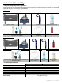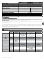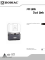
1
Instructions for installation and use
English
More documents on:
www.zodiac-poolcare.com
H0493700.A - 2014/07
•Read this notice carefully before installing, maintaining or repairing this appliance!
•The
symbol indicates important information that must be taken into consideration in order to
avoid risk of harm to persons or damage to the appliance.
•The
symbol indicates useful information.
Warnings
•As part of a continuous improvement process our products may be modified without prior notice.
•Exclusive use: regulation system for pools (must not be used for any other purpose).
•System designed to work with water from the public network. The use of water from wells or rain
water is prohibited.
•The installer is liable for the installation of the appliance and the compliance with local regulations
in matters of installation. Under no circumstances can the manufacturer be held liable in the event of
failure to comply with applicable local standards. Under no circumstances shall the manufacturer be
held liable if current local installation regulations are not followed.
•It is important that this equipment is operated by competent and qualified (both physically and
mentally) people that have previously received the instructions for use (by reading this booklet).
Any person not meeting these criteria should not go near the equipment, to avoid the risk of being
exposed to dangerous components.
•If the equipment malfunctions: do not attempt to repair the equipment yourself – contact your
installer.
•Before working on the equipment, ensure that it and any other equipment connected to it are
disconnected from the electricity supply.
•Before connecting it to the electricity supply, check that the voltage marked on the equipment
matches the mains supply voltage.
•Removing or bypassing one of the safety devices automatically voids the guarantee, as does fitting
replacement parts not manufactured by us.
•Incorrect installation can result in damaged equipment or serious physical injury (or even death).
•Keep the equipment out of the reach of children.
•The pH Link or Dual Link module is only designed to use pH minus (special liquid for use in swimming
pools). Use of other products automatically voids the guarantee.
1
H0493700.A - EN - 2014-07
Contents
1. Information before installing...................................................................................................... 3
1.1 General delivery terms and conditions................................................................................................ 3
1.2 Contents......................................................................................................................................................... 3
1.3 Technical specifications............................................................................................................................. 3
2. Installation................................................................................................................................................ 4
2.1 Preparing the pool: water balance........................................................................................................ 4
2.2 Installing the pH Link or Dual Link module.......................................................................................... 5
2.3 Installing the POD Kit................................................................................................................................. 5
3. Use.................................................................................................................................................................. 8
3.1 Activating the module............................................................................................................................... 8
3.2 Display............................................................................................................................................................ 8
3.3 Calibrating the sensor(s)........................................................................................................................... 8
3.4 Adjusting the set point(s)......................................................................................................................... 9
3.5 Setting the pool volume............................................................................................................................ 9
3.6 Peristaltic pump......................................................................................................................................... 10
4. Maintenance......................................................................................................................................... 10
4.1 Cleaning the sensor(s)............................................................................................................................. 10
4.2 Wintering..................................................................................................................................................... 11
5. Troubleshooting.................................................................................................................................. 11
6. Registering the product................................................................................................................. 12
7. Product conformity.......................................................................................................................... 12
H0493700.A - EN - 2014-07
2
1. Information before installing
1.1 General delivery terms and conditions
All equipment, even postage and packing paid, travels at the risks and perils of the recipient. If damaged caused during
transport is observed, the recipient should write appropriate comments on the delivery note provided by the carrier (and
confirmed in writing to the carrier by registered letter).
1.2 Contents
1.2.1 pH Link module
pH Link module
POD kit
Accessory bag (counterweight + securing clip,
PTFE tape and stoppers)
pH sensor
Buffer solution pH 7.5
suction + injection hose
(5 meters)
Hole saw, 22 mm
1.2.2 Dual Link module
Dual Link module
POD kit
Accessory bag (counterweight + securing clip, PTFE
tape and stoppers)
pH sensor
ACL sensor
Hole saw, 22 mm
suction + injection
hose (5 meters)
Buffer solution
pH 7.5
Buffer solution
700 mV
1.3 Technical specifications
Supply voltage
Peristaltic pump flow rate
Maximum back pressure (injection)
pH and ACL sensor type
pH and ACL sensor electrolyte
pH and ACL sensor cable(s)
pH correction
3
pH Link module
Dual Link module
Low voltage (connected to the power pack)
1.8 L/h
1.5 bar
combined, ABS 1/2’’ NPT threaded body (pH = blue / ACL = red)
KCI polymer
1.5 meters shielded, BNC plug (pH = blue / ACL = red)
acid (pH minus only)
H0493700.A - EN - 2014-07
pH Link module
pH minus dosage
pH sensor tolerances
Measurement scale & pH sensor accuracy
pH sensor calibration
ACL sensor tolerances
Measurement scale & ACL sensor accuracy
ACL sensor calibration
pH and ACL sensor response time
Dimensions (w x h x d)
Weight (module only)
Protection index
Dual Link module
Proportional cyclic
Flow speed 2 metres/second - 5 bar / 60°C
pH 0.0 to pH 12.0, ± 0.1 pH
1 point, pH 7.5
Flow speed 2 metres/second /
5 bar / 60°C
/
100 mV to 1000 mV / ± 10 mV
/
1 point, 700 mV
< 15 seconds
28.5 x 15.5 x 7.5 cm
1 kg
IP23
2. Installation
2.1 Preparing the pool: water balance
The Zodiac® electrolyser or MagnaPool™ hydroxinator is designed to disinfect the water in the pool by means of its salt
chlorination function.
With the pH Link module, it automatically maintains the pH value of your pool.
With the Dual Link module (electrolyser only), it automatically maintains the pH value and chlorine level (ACL or Redox
potential) of your pool.
It is essential that the pool water balance is controlled and adjusted before installing the appliance. Making sure that the
pool water balance is correct from the very start will reduce the likelihood of encountering problems on the first days of
operation or during the season the pool is in use.
Even if it is an automatic control system, it is essential to analyse the water regularly to check the water balance
parameters.
Unit
Recommended
values
To increase
To reduce
Test frequency
(in the season)
pH
/
7.2 – 7.4
Deactivate dosage
or add pH+
Automatic
(pH minus Perfect pHor pH-)
Weekly
Free
chlorine
mg/L or
ppm
0.5 – 2
Decrease ACL set point
or turn off the unit
Weekly
TAC
(alkalinity or
buffering power)
°f (ppm)
8 – 15
(80 – 150)
Add hydrochloric acid
Monthly
°f (ppm)
10 – 30
(100 – 300)
Add calcium
Add a calcium carbonate
sequestering agent
(Calci-) or carry out
carbonate removal
Monthly
mg/L or
ppm
< 30
/
Partially empty the pool
and refill it
Quarterly
mg/L or
ppm
±0
/
Add a metal fixer
(Metal Free)
Quarterly
TH
(calcium hardness)
Cyanuric
acid
(stabiliser)
Metals
(Cu, Fe, Mn…)
H0493700.A - EN - 2014-07
Increase ACL
set point or add
chlorine
Add alkaline
corrector
(Alca+ or TAC+)
4
2.2 Installing the pH Link or Dual Link module
1
2
3
4
• Turn off your power pack then the filtration by cutting
off the main electricity supply in order to isolate the
installation.
• Close the isolating valves in the pipework.
• Remove the silver cover by pressing the sides and raising
it ( 1 ), then unscrew the four screws attaching the
original (empty) lower module to the power pack ( 2 ).
• Remove the empty module and present the pH Link or
Dual Link module to be installed ( 3 ).
• Connect the ribbon cable from the pH Link or Dual Link
to the connector on the power pack ( 4 ).
• Put the pH Link or Dual Link module in position, replace
the four screws and replace the silver cover.
• Do not reconnect the electricity supply until the pH Link or Dual Link module, the sensor-holding POD Kit and
the pH minus injection pipe have been installed (see § 2.3.3).
• Always wait 2 minutes, particularly when performing any technical work, between disconnecting the power
packfrom the mains electricity supply and connecting the pH Link or Dual Link module.
2.3 Installing the POD Kit
The sensor-holding POD Kit is a single assembly including the flow rate detector (used by your appliance, see § 2.3.2), the
pH and ACL sensors and pH minus injection.
• The cell bypass valves must always be open.
• The sensor-holding POD Kit must always be positioned on a horizontal pipe so that the sensors are vertical ( 1
or 2 ).
• The POD Kit must be the first unit fitted after the pool filter.
• If the pool is fitted with a heating system (heat pump, heat exchanger, electric heater, etc.), the POD Kit must
be installed before it ( 3 ) (to take readings on unheated water).
• We recommend positioning the POD Kit more than 20 cm from an elbow in the pipe.
• The sensor cables must not be positioned near high voltage mains electricity cables.
Inline installation
1
pH sensor
2
By-pass installation
3
Installation with heating system
pH minus injection
ACL sensor
Flow controller
Water circulation direction
5
H0493700.A - EN - 2014-07
A badly-installed sensor may give false readings and cause inappropriate operation of the appliance. Neither the
manufacturer nor the unit shall be liable in this event.
2
1
Identify a suitable length (minimum 30 cm, without elbow) of
straight pipe.
• Dismantle the POD Kit and keep the lower part with 2 holes ( 1 ).
• Turn the lower part of the collar upside down and place it in the
position where you want to install it on the pipe.
• Use a center-punch or marker pen to mark the position of the
holes to be made in the pipe ( 2 ).
• Using the holes saw supplied, cut the 2 feed holes for the POD Kit.
Ensure that the edges of the holes are smooth and deburred!
• Place the upper part of the POD Kit on the pipe, sliding it into the previously-drilled holes.
The arrows on the upper part of the POD collar show the direction of water flow.
Reducer (labelled
“EU”) Ø50 mm
Collar Ø63
• Click the 2 parts of the POD Kit collar together around the pipe. For a Ø50 mm pipe, use the
reducer labelled 'EU'. Do not use this reducer for a Ø63 mm pipe.
• Position the upper part of the POD Kit with its various components in the direction indicated
by the foolproof locating notch and tighten the locking ring firmly (hand-tighten only).
2.3.1 Installing the pH and ACL sensors
• Carefully unscrew the protection cap from the sensor ( 1 ).
• Rinse the end of the sensor with tap water and shake off excess water.
1
Never wipe the sensor using a cloth or paper tissue, as this may damage it!
• Screw the sensor into the threaded hole on the POD Kit until the O-ring seal on the sensor
comes in contact with the POD kit ( 2 ). Do not use excess strength. If necessary, use the
supplied Teflon band.
• Connect the supplied BNC cable to the top of the sensor.
2
Do NOT screw/unscrew the sensors while they are still connected to their BNC
cables. Disconnect the cables beforehand to avoid damage.
• Once the sensors are installed they may be connected to the BNC sockets on the power
pack named " pH" (blue) and "ACL" (red). They must now be calibrated (see § 3.3).
H0493700.A - EN - 2014-07
6
2.3.2 Installing the flow switch
2 positions possible:
1
2
• After the upstream valve if the cell is
in by-pass ( 1 )
• On the POD kit, if the cell is inline
( 2 )
a) pH Link or Dual Link module
installed at the same time as the power pack.
• Locate the flow switch supplied with the power pack.
• Screw the flow switch into the seat provided on the POD Kit (hand-tighten).
The arrow that indicates the water flow rae on the top of the flow switch must be perfectly parallel with the
pipes on which the POD kit is positioned.
b) pH Link or Dual Link module added to an installation already equipped with a power packl
When the swimming pool already has a power pack, the flow switch is already installed. Leave the flow switch in place.
Unscrew the threaded adaptor located on the POD Kit and replace it with the stopped supplied to seal the hole.
2.3.3 Installing the pH minus injection line
When handling chemical products, always use appropriate safety equipment (safety glasses, gloves and jacket).
a) Installing the injection line (peristaltic pump > non-return valve)
• Remove the protective cover from the peristaltic pump,
• Cut a suitable length of pipe from the coil supplied to connect the
peristaltic pump to the injection non-return valve located on the
POD Kit
• Attach the pipe to the threaded connector on the peristaltic
pump outlet.
• Attach the other end of the pipe to the injection non-return valve.
pH Link
Dual Link
b) Installing the intake pipe (container > peristaltic pump)
• Cut a suitable length of pipe from the coil supplied to connect the
container of pH minus to the peristaltic pump.
• Attach the pipe to the threaded connector on the peristaltic
pump inlet.
• Make a hole to fit the diameter of the intake pipe in the cap of
the pH minus container and another smaller hole to avoid the
container distorting as the product is sucked up.
• Pass the free end of the pipe through the hole made in the cap
and put the ceramic counterweight and threaded locking nozzle
on the end.
• Ensure that ALL connections are correct and watertight before
operating the pH Link or Dual Link module.
• Replace the protective cover on the peristaltic pump.
7
H0493700.A - EN - 2014-07
3. Use
3.1 Activating the module
The power pack automatically detects the presence of a pH Link or Dual Link module. It is now ready to be used with
automatic pH control using the pH Link module or pH and ACL control using the Dual Link module.
3.2 Display
The LCD screen will display 2 extra lines:
- pH Link module:
pH set point
- Dual Link module:
pH set point
ACL set point
A '^' symbol appears to the right of the set point if the value measured by the equipment needs to be corrected automatically
(pH of water in the pool higher than the set point and/or insufficient chlorine level). Then pH minus is injected and/or
chlorine produced automatically according to the defined cycles.
By default, pH regulation (peristaltic pump in the module) is disabled and the LCD screen will display 'pH ---'.
It is enabled automatically about 8 hours after being turned on. To enable pH regulation immediately and so display the set point on the LCD screen, see § 3.6.2.
3.3 Calibrating the sensor(s)
• To operate accurately and reliably, the sensors must be calibrated before using the power pack with the module.
To maintain maximum efficiency of the unit, we recommend calibrating at least once every 2 months during the
period the swimming pool is being used.
• Ensure the sensors are cleaned before calibration (see § 4.1).
• Confirm that the power pack is plugged in,
• Stop the pool pump and isolate the sensors by closing any valves, so as to be able to
remove the sensors safely.
• Disconnect the BNC cable from the top of each sensor then remove them (unscrew) from
the POD. Then reconnect the BNC cable to the sensors.
• Rinse the end of the sensors with clean water and shake them to remove excess water.
Do not touch or wipe the glass bulb at the end of the sensors.
• Put the pH sensor into a sample of the pH7.5 buffer solution supplied.
• Put the ACL sensor into a sample of the 700 mV buffer solution supplied.
• Leave the sensors immersed for about 1 minute to obtain a reliable measurement.
• Press
or
• then press
• Use the
press
the use the
or
or
or
or
keys to display "CALIB. PH" or "CALIB. PH\ACL",
.
keys to display "CALIBRAGE PH" (pH Link and Dual Link) or " CALIBRAGE ACL" (Dual Link only) then
.
Note the measured value:
• pH = 'X.X'
-- If the value is greater than 8.2 or less than 6.4: the sensor is dirty or has been damaged during transport. Clean the pH
sensor (see § 4.1) then repeat the above steps. If the problem persists, contact your reseller.
-- If the value is between 6.4 and 8.2, press
H0493700.A - EN - 2014-07
or
to begin calibration. The procedure takes about 15 seconds.
8
-- When calibration is finished, check that the value displayed equals 7.5, otherwise repeat the calibration.
• ACL = 'XXX'
-- Start the calibration procedure by pressing
or
, the procedure lasts about 15 seconds,
-- If the value is 700: calibration is correct
-- If the value is not 700: repeat the calibration steps. If the problem persists, contact your reseller.
• Press
or
or wait 30 seconds to exit.
3.4 Adjusting the set point(s)
The set point is displayed continuously on the LCD home screen.
The default setting for the pH set point is pH7.2 (pH Link and Dual Link modules).
The default setting for the ACL set point is 4 (Dual Link module).
This value provides the ideal compromise to achieve optimum efficiency in terms of water disinfection.
• Calibrating the sensors (see § 3.3).
• Press
or
the use the
or
keys to display "CALIB. PH" or "CALIB. PH\ACL", then press
or
.
• Use the
or
keys to display 'PH SET POINT' or 'ACL SET POINT', then press
• Use the
or
keys to change the set point value.
• Press
or
or
.
or wait 30 seconds to exit.
• The ACL set point displayed does not match the free chlorine concentration in the pool. This is the desired level
of 'disinfection potential' in the water.
• The ACL set point required to reach the optimum chlorine level is different in every swimming pool. A period
manual measurement of free chlorine level in the pool is therefore necessary to adjust this ACL set point.
• To increase the chlorine production potential: increase the ACL set point.
• To decrease the chlorine production potential: decrease the ACL set point.
Dual Link module only:
We recommend that you check the free chlorine level in the pool a few days after the module is installed to
determine if the rate is ideal (0.5 to 2 ppm, see §2.1). If, after this period, the free chlorine level is unsuitable,
the ACL set point must be changed.
3.5 Setting the pool volume
List of levels with corresponding volumes:
• Level 1: For small pools up to 40 m³
• Level 2: For mid-size pools from 40 to 60 m³ (default level)
• Level 3: For large pools between 60 and 110 m³
• Level 4: For very large pools over 110 m³
• These values are for guidance only; the choice may vary according to the conditions of use.
• When the volume of the pool is at the limit between 2 levels, it is better to use the higher level.
• However, we recommend not 'over-sizing' the choice of level, to avoid using too much pH minus.
• A dose of pH minus is injected into the pool every 2 hours (when the filtration and water treatment systems
are running).
9
H0493700.A - EN - 2014-07
• Press
or
the use the
or
keys to display "CALIB. PH' or 'CALIB. PH\ACL", then press
or
.
• Use the
or
keys to display 'POOL VOLUME', then press
• Use the
or
keys to select the desired level appropriate to the pool size.
• Press
or
to confirm the choice then press
or
or
.
or wait 30 seconds to exit.
3.6 Peristaltic pump
3.6.1 Test / priming the peristaltic pump
After installation, we recommend testing the peristaltic pump for the module and priming it (system normally self-priming).
• Before testing the peristaltic pump, ensure that all pH minus suction and injection pipes are correctly connected.
• Always use appropriate safety equipment when handling chemical products.
• Switch on the power pack (
• Press
or
.
or
• Use the
button).
, then use the
or
or
keys to display “CALIB. PH" or "CALIB. PH\ACL", then press
keys to display “TEST DOSAGE”.
• A warning will be displayed briefly, then press
or
operate for about 30 seconds and will stop automatically.
to confirm starting the pump. The peristaltic pump will
• If the pump must be stopped immediately, press
or
.
• Confirm that the pump is primed (pH minus solution will be visible in the translucent pipes).
To prime the peristaltic pump more quickly, it may be necessary to repeat these steps several times, depending on
the length of the pH minus feed line.
3.6.2 Activating / deactivating the peristaltic pump
For safety reasons the peristaltic pump is not activated when delivered.
When the pH Link or Dual Link module is connected to the power pack, the peristaltic pump is programmed to start
approximately about 8 hours after being turned on. During this period, the default display on the LCD screen will show
“pH ---”.
To activate the peristaltic pump immediately:
or
• Press
press
or
or
keys to display “CALIB. PH” or “CALIB. PH\ACL" then
.
or
• Use the
activated).
• Press
OFF”).
, then use the
or
keys to reach the “DOSAGE OFF” (or “DOSAGE ON” line if the pump had previously been
to activate the peristaltic pump (“DOSAGE ON”) or deactivate the peristaltic pump (“DOSAGE
4. Maintenance
4.1 Cleaning the sensor(s)
• If the end of the sensor is coated with a greasy film (deposits of cosmetics, suntan lotion, etc.), soak it for a few minutes
in warm soapy water. Warning: do not use a detergent, dishwashing liquid is better.
• If the end of the sensor is coated with limescale or if the above procedure is not enough, soak the sensor in a 10%
diluted solution of hydrochloric acid for a few minutes (wear the necessary safety equipment).
• Rinse thoroughly with clean water.
• Calibrate the sensor again (see § 3.3).
H0493700.A - EN - 2014-07
10
This acidic cleaning solution can be bought from your reseller or you can make it up yourself by mixing 1 volume
of acid with 9 volumes of clean water in a suitable container. ALWAYS ADD ACID TO WATER, NEVER THE OTHER
WAY AROUND!
• Always clean the sensor before carrying out the calibration procedure.
• During cleaning, NEVER WIPE THE SENSOR WITH A CLOTH but shake it gently to remove excess rinse water.
4.2 Wintering
• Rinse the peristaltic pipe by pumping clean water instead of pH minus solution, using the “TEST DOSAGE” function (see
§ 3.6.1).
• Unscrew the POD sensors (disconnect their BNC cable beforehand). Place them in their original protective caps or in
a container filled with tap water.
• If necessary close the POD holes using the threaded stops.
NEVER leave a sensor to dry and/or exposed to the risk of frost, which would permanently damage it.
5. Troubleshooting
Message
PH LOW
Causes
The measured 0.8 PH units or more below the set
point
The pH sensor is dirty, out of calibration or not
working
PH ERROR
The pool size setting is too large
pH adjustment has performed 5 cycles without
reaching its set point (> 10 hours)
The pH minus container is empty
The peristaltic pump is not primed
The pH sensor is dirty, out of calibration or not
working
ACL HIGH
The pool size setting is too small
The peristaltic pump has not been operated for a
total of more than 72 hours
The measured Redox potential is more than 150
mV above the set point (the chlorine level may be
excessive)
The pH is too low
ACL ERROR
The ACL regulation authorised chlorine production
for a total of over 30 hours without waiting for the
ACL set point
The appliance has not produced any chlorine for a
total of over 30 hours
11
Solutions
Check the pH in the pool
Check the set point
Calibrate or replace the pH sensor
Clean and calibrate the sensor
Replace the pH7.5 buffer solution if necessary
Check the selected pool size
Check the pH in the pool
Calibrate or replace the pH sensor
Replace the container
Test the peristaltic pump
Clean and calibrate the sensor
Replace the pH7.5 buffer solution if necessary
Check the selected pool size
The pH in the pool does not need to be corrected
Clean and calibrate the sensors
Wait until the error message disappears (no
chlorine production)
Make sure that the stabiliser is lower than 30
ppm
Reduce the ACL set point
Make sure that the water's alkalinity level is OK
(well and rain water prohibited)
Check the pH in the pool
Clean and calibrate the sensors
Replace the buffer solutions if necessary
Replace the sensors
Use "Boost" mode if necessary
Check the pH in the pool
Clean and calibrate the sensors
Replace the buffer solutions if necessary
Replace the sensors
H0493700.A - EN - 2014-07
To cancel the "PH ERROR" and "ACL ERROR" messages, press
or
for 3 or 4 seconds when the message
appears.
The other codes are only information messages that disappear automatically when the operating conditions
return to optimal.
6. Registering the product
Register your product on our website:
--You will be the first to be informed of new Zodiac® products and special offers,
--You can help us to constantly improve our product quality.
Europe & Rest of the World
www.zodiac-poolcare.com
America
www.zodiacpoolsystems.com
Australia – Pacific
www.zodiac.com.au
7. Product conformity
This appliance has been designed and built according to the following standards:
EN6000-6-1: 2006
EN6000-6-3: 2007
IEC 61558-2-6: 1997
AS/ NZ 3136-2001 (IEC 60065 + IEC 60335-2-60)
Relative to which it is compliant. The product has been tested under the normal conditions of use.
H0493700.A - EN - 2014-07
12
Pour plus de renseignements, merci de contacter votre revendeur.
For further information, please contact your retailer.
ZODIAC® is a registered trademark of Zodiac International, S.A.S.U., used under license.
Zodiac Pool Care Europe - BP 90023 - 49180 St Barthélémy d’Anjou cedex - S.A.S.U. au capital de 1 267 140 € / SIREN 395 068 679 / RCS PARIS
www.zodiac-poolcare.com
Votre revendeur / your retailer