1
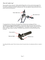
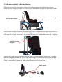
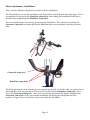
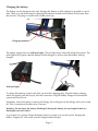
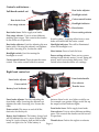
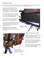
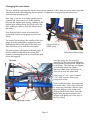
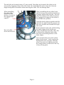
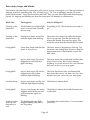
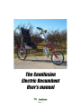
The Semifusion
Electric Recumbent
User’s manual
Page :1
How do I make it go?
First remember, this is a bicycle. All the standard things that one does to ride a bicycle apply. The
front brake is controlled by the right brake lever and the rear is controlled by the left brake lever.
You pedal and shift gears, just like a standard bicycle. The only difference being, this bicycle has an
electric motor that can help out.
Front brake lever
Rear brake lever
To operate the motor. First turn on the electronics with the bicycle standing still. This is
accomplished by turning the power switch on the top of the right control block clockwise to the
right. The indicator lights should blink and you should hear a single long beep. This means that the
motor is ready to work. Now, press the throttle lever , on the bottom of the right hand control
block, to the right a little to accelerate. The further you push the lever, the more the bicycle will
accelerate.
Power switch
Indecator lights
Throttle lever
Try riding the bike around. Take it slowly at first. Get used to how it accelerates and how to make it
stop.
Page :2
A little more comfort? Adjusting the seat.
The seat base is held in place by two clamps. One in the front and one in the back of the seat.
Loosening these clamps will allow the seat base to be moved back and forth on the bicycle’s frame.
Front seat base clamp
Rear seat base clamp
The seat back is held in position by two telescoping braces. These braces are locked into position by
a pair of snap pins. The seat back can be adjusted by removing these two pins. Once the pins are
removed, the seat back braces can be telescoped. Different pairs of adjustment holes can be aligned.
Seat back locking
snap pins
The rear seat clamp can be positioned either in front of or behind the rear frame brace. To change
this, the clamp must be removed. If you remove this clamp, be mindful that there is a small metal
spacer that will fall free when the clamp bolt is removed. This spacer must be reinstalled when the
clamp is reassembled. It keeps the clamp from deforming the seat base frame.
Metal Spacer
Page :3
More adjustments, handlebars:
There are three different adjustments possible with the handlebars.
The first effectively moves the handlebars back and forth by adjusting their mounting angle. This is
accomplished by loosening the Handlebar clamp bolts and rotating the handlebars backward or
forward, then retightening the Handlebar clamp bolts .
The second adjustment is for raising or lowering the handlebars. This is done by loosening the
Gooseneck clamp bolt and either pulling the handlebar tube out or pushing it into the gooseneck
tube.
Gooseneck clamp bolt
Handlebar clamp bolts
The third adjustment can be affected by reversing the gooseneck. To do this, first you must remove
the handlebars from the gooseneck. This is done by removing the Handlebar clamp bolts . Next,
loosen the Gooseneck clamp bolt . Once it is loose, turn the gooseneck 180 degrees. Retighten the
Gooseneck clamp bolt. Lastly, remount the handlebars. Reversing the clamp from the stock
position will gain a few extra inches of leg room under the handlebars.
Page :4
Charging the battery:
The battery can be charged at any time. Keeping the battery as fully charged as possible is a good
idea. There is an electrical plug for charging the batteries located at the bottom of the frame, near
the rear tire. This plug is covered with a rubber dust cap.
Charging connector
The battery charger has two indicator lights . The red light shows when the charger has power. The
other light will be green when the battery is fully charged, or yellow when the battery is being
charged.
Indicator lights
To charge the batteries, remove the dust cap from the charging plug. Plug the battery charger,
which is supplied with the bicycle, into this connection. Plug the battery charger into household
current and switch it on.
Sometimes, when the battery is nearing full charge, the cooling fan on the charger will cycle on and
off. This is normal and should not be a concern.
Warning : Do not leave the battery discharged. Storing the battery for any lengh of time in a
discharged state will ruin it.
A good plan is to always charge the battery after every time you use the bycicle. Keeping the
battery “topped off” will assure you the longest battery lifespan.
Page :5
Controls and features :
Left hand control set
Rear brake adjustor
Headlight switch
Rear brake lever
Gear range selector
Cruise control button
Headlight indicator
Horn button
Rear brake lever: Pull to apply rear brake.
Gear range selector : Twist to select different
pedaling gear ranges. This controls the derailer
on the front set of sprockets.
Rear brake adjustor: Used for adjusting the rear
brake cable. Screwing the adjustor out tightens
the cable. Screwing it in, loosens the cable.
Power setting selector
throttle setting. Applying either front or rear
brake will deactivate the cruise control.
Headlight indicator: This will be illuminated
when the headlight is on.
Horn button: Press to honk the horn.
Headlight switch: Used for turning the
headlight on or off.
Cruise control button: This activates the cruise
control. The cruise control holds the current
Power setting selector: There are two power
settings for the electric motor. Normal, being full
power, and Economy being half power. This
switch selects between these two settings.
Right hand control set
Front brake adjustor
Power switch
Battery level indicator
Front brake adjuster: Used for adjusting the
front brake cable. Screwing the adjuster out
tightens the cable. Screwing it in, loosens the
cable.
Front brake handle
Gear selector
Throttle lever
between these levels, two lights would be on.
For example one quarter charge would lite up
the empty and half indicator lights.
Front brake lever: Pull to apply front brake.
Power switch: This turns on and off all the
electonics for the bicycle.
Gear selector: Twist to select different pedaling
gears. This controls the derailer on the rear set
of sprockets.
Battery level indicator: The battery charge level
will be indicated by one or more of these lights
Throttle lever: Push to the right to accelerate.
being lit. Levels of empty, half and full would
cause one light to be on. If the battery is
Page :6
Replacing the fuses:
If an over current condition arises the electronic drive is protected by two 20 Amp fuses. It might be
a good idea to carry a set of spare fuses just in case of a failure of this type.
The fuses are located under the drive
batteries inside the battery case. The
battery case covers are held in place by
two allen head screws. These screws are
removed using a 1/8” Allen wrench.
When removing the battery cover you
may need to squeeze down the top of the
cover a little, so that the top of the cover
clears the seat mounting hardware.
Once the battery covers are removed, the
fuses can be seen mounted under the
front corners of the battery brackets.
Typically, when one fuse burns out, it will
cause the second fuse to burn out as well.
For this reason, the fuses should always
be replaced as a set.
Pull the old fuses out of their sockets,
then push in fresh fuses. Once this is
accomplished, you can replace the battery
case covers.
Battery case cover
mounting screws
What causes the fuses to fail?
The most common cause for fuse failure,
is having the batteries charged
unevenly. Typically this is noticed after
using high power, such as hill climbing.
To minimize your risk of this type of
failure, don’t use mismatched batteries.
When replacing the drive batteries,
always replace them as a set.
Faulty wiring could be another cause for
fuse failure. If you suspect faulty wiring,
contact your Semifusion dealer.
Locating the fuses,
looking from below and
behind the battery case.
Page :7
Changing the rear wheel:
The rear wheel incorporates the electric drive motor. Because of this, there are a few extra steps that
must be followed when changing the rear wheel. As opposed to changing the rear wheel on a
standard unpowered bicycle.
First step, of course, is to make sure the power
is turned off. Once the power is off, shift the
bike into the highest gear setting. Shifting to the
highest gear setting moves the chain out of the
way, making it easier to slide the wheel out of
the frame.
Now that the bike is ready, disconnect the
power and control circuit plugs near the rear
wheel.
The control circuit plug is the smaller of the two
plugs. Its is disconnected by squeezing in the
small plastic latch on the side of the plug case.
This will allow you to slide the cases apart.
Squeeze latch on
smaller plug.
The power plug is the larger of the two plugs. It
too has a latch on the side of its casing. But
instead of pushing the latch in, you pull the latch
out to disengage it.
Pull latch on larger plug.
Once the plugs are disconnected,
carefully clip the tiewraps holding the
wiring harness between the wheel hub
to the plugs. The tiewraps are clipped
in order that when the wheel is
removed, these wires will be free to
come away with the wheel hub.
Tiewraps
Next, using a 7/16” open end and a
5/32” allen wrench, remove the
torque arm screw.
Now, under the frame, disconnect the
rear brake cable. This can be achieved
by squeezing the brake calipers open
from the bottom of the frame and
sliding out the brake cable. Once the
brake cable has been detached, the
calipers will spring out of the way of
the rear wheel.
Torque arm screw
Page :8
The axle bolts are loosened using a 17 mm wrench. Once these are loosened, the wheel can be
removed by dropping it down out of the frame. Be careful that the motor wires don’t become
tangled and pulled or stretched when removing the wheel. This can damage them.
When reinstalling
the wheel, slide
torque arm thru
this area. in front of
the luggage rack
support.
When reinstalling the rear wheel, start
with the torque arm positioned at about a
45 degree angle facing forward. This will
allow the torque arm to slide forward of
the luggage rack support as the wheel is
moved back into position.
Once the wheel is back in position and the
axle bolts are tight. Rotate the torque arm
back into position and reinstall the torque
arm screw.
Reach under the frame and, while holding
the brake caliper closed on the rear
wheel, reinstall the rear brake cable. This
is achieved by sliding the brake cable
back into its mounting bracket on the
brake caliper.
Rear axle slides
down and forward.
Now reconnect the power and control
plugs for the motor. Lastly, replace the
tiewraps that were cut away when the
wheel was removed. Making sure that
the wiring harness is held out of the way
of any moving parts.
Page :9
Error codes, beeps and blinks:
From time to time the bicycle’s electronics will want to convey a message to you. The typical kind of
message would be something like “Ok, all ready to go.” Or “I’m overheating, maybe you could
pedal a little harder?” Now, the electronics can’t talk. They can only blink lights and make beeping
sounds. So, beeping and blinking are how the electronics will attempt to communicate.
While I’m...
This happens..
And, its telling me?
Turning on the
electronics.
All the battery level lights light
up for a second and it sounds
off one beep.
Everything is Ok. The electronics are ready to
go.
Turning on the
electronics.
It beeps four times and all the
indicator lights start blinking.
The power was turned on while the throttle
lever was pressed. Turn the electronics off,
release the throttle lever and try again. This
could also mean that the throttle itself is faulty.
Going uphill.
I hear three beeps and the bike
seems to lose power.
The drive motor is beginning to heat up. The
electronics are cutting drive power to keep the
temperature down. Pedal harder or give the
bike a rest.
Going uphill.
It gives four beeps, the motor
stopped and a red indicator
light is flashing.
The drive motor has overheated and has shut
down. Don’t worry, this doesn’t damage
anything. Let it rest and cool for a few minutes
and you can be on your way again.
Going uphill.
It gives four beeps, the motor
stopped and a the yellow
indicator light is flashing.
The drive electronics have overheated and
have been shut down. Let them cool for a few
minutes and you can be on your way again.
Cruising along..
It gives four beeps and the red
indicator light begins flashing.
The battery is almost dead.
Going uphill.
It gives four beeps, the motor
stopped and both the red and
yellow indicator lights are
flashing.
The battery is almost dead and the motor has
overheated.
Waiting for the
motor or the
electronics to
cool.
The flashing indicator light
stopped flashing and there is
one long beep.
Everything has cooled down. You can resume
your ride.
Page :10