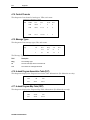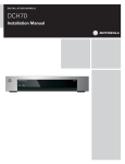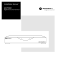
1
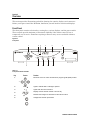
Installation Manual DCT2500 Digital Consumer Terminal MESSAGES REMOTE ON CURSOR CHANNEL SELECT GUIDE POWER MENU INFO Graphical symbols and supplement warning marking locations on the bottom of the appliance. This symbol indicates that dangerous voltage levels are present within the equipment. These voltages are not insulated and may be of sufficient strength to cause serious bodily injury when touched. The symbol may also appear on schematics. This symbol calls attention to a critical procedure, or means refer to the instruction manual for opening or service information. Only qualified service personnel are to install or service the equipment. The symbol may also appear in text and on schematics. WARNING: TO PREVENT FIRE OR SHOCK HAZARD, DO NOT EXPOSE THIS APPLIANCE TO RAIN OR MOISTURE. CAUTION: TO PREVENT ELECTRICAL SHOCK, DO NOT USE THIS PLUG WITH AN EXTENSION CORD, RECEPTACLE, OR OTHER OUTLET UNLESS THE BLADES CAN BE FULLY INSERTED TO PREVENT BLADE EXPOSURE. FCC Compliance: Federal Communications Commission Radio and Television Interface Statement for a Class ‘B’ Device This equipment has been tested and found to comply with the limits for a Class B digital device, pursuant to part 15 of the FCC Rules. These limits are designed to provide reasonable protection against harmful interference in the residential installation. This equipment generates, uses and can radiate radio frequency energy and, if not installed and used in accordance with the instructions, may cause harmful interference to radio communications. However, there is no guarantee that interference will not occur in a particular installation. If the equipment does cause harmful interference to radio or television reception, which can be determined by turning the equipment off and on, the user is encouraged to try to correct the interference by one of the following measures: Increase the separation between the equipment and the affected receiver Connect the equipment on a circuit different from the one the receiver is on Ensure that the cover plate for the security card is secured and tight Changes or modification not expressly approved by the party responsible for compliance could void the user’s authority to operate the equipment. Declaration of Conformity: According to 47 CFR, Parts 2 and 15 for Class B Personal Computers and Peripherals; and/or CPU Boards and Power Supplies used with Class B Personal Computers, Motorola, Inc., 6450 Sequence Drive, San Diego, CA 92121, 1-800-225-9446, declares under sole responsibility that the product identifies with 47 CFR Part 2 and 15 of the FCC Rules as a Class B digital device. Each product marketed is identical to the representative unit tested and founded to be compliant with the standards. Records maintained continue to reflect the equipment being produced can be expected to be within the variation accepted, due to quantity production and testing on a statistical basis as required by 47 CFR 2.909. Operation is subject to the following condition: This device must accept any interference received, including interference that may cause undesired operation. The above named party is responsible for ensuring that the equipment complies with the standards of 47 CFR, Paragraphs 15.107 to 15.109 FCC Part 68 Statement: This equipment complies with part 68 of the FCC rules. On the rear panel of this equipment is a label that contains, among other information, the FCC registration number and ringer equivalence number (REN) for the equipment. If requested, this information must be provided to the telephone company. The REN is used to determine the quantity of devices that may be connected to the telephone line. Excessive RENs on the telephone line may result in the devices not ringing in response to an incoming call. In most, but not all areas, the sum of the RENs should not exceed five (5.0). To be certain of the number of devices that may be connected to the line, as determined by the total RENs, contact the telephone company to determine the maximum REN for the calling area. This equipment uses the following USOC jack: RJC. An FCC-compliant telephone cord and modular plug is provided with this equipment. This equipment is designed to be connected to the telephone network or premises wiring using a compatible modular jack that is Part 68 compliant. This equipment cannot be used on telephone company-provided coin services. Connection to Party Line Service is subject to state tariffs. If this equipment causes harm to the telephone network, the telephone company will notify you in advance that the temporary discontinuance of services may be required. If advance notice isn’t practical, the telephone company will notify the customer as soon as possible. Also, you will be advised of your right to file a compliant with the FCC if you believe it is necessary. The telephone company may make changes in its facilities, equipment, operations, or procedures that could affect the operation of the equipment. If this happens, the telephone company will provide advance notice in order to maintain uninterrupted service. If the trouble is causing harm to the telephone system, the telephone company may request that you remove the equipment from the network until the problem is resolved. It is recommended that the customer install an AC surge arrestor in the AC outlet to which this device is connected. This is to avoid damaging the equipment by local lightning strikes and other electrical surges. Canadian Compliance: This Class B digital apparatus meets all requirements of the Canadian Interference-Causing Equipment Regulations. Cet appareil numérique de la classe B respects toutes les exigences du Règlement sur le matériel brouilleur du Canada. Industry Canada CS-03 Statement: The Industry Canada label identifies certified equipment. This certification means that the equipment meets certain telecommunications network protective, operational and safety requirements as prescribed in the appropriate Terminal Equipment Technical Requirements document(s). The department does not guarantee that the equipment will operate to the user’s satisfaction. Before installing this equipment, users should ensure that it is permissible to be connected to the facilities of the local telecommunications company. The equipment must also be installed using an acceptable method of connection. The customer should be aware that compliance with the above conditions might not prevent degradation of service in some situations. Repairs to certified equipment should be coordinated by a representative designated by the supplier. Repairs or alterations made by the user to this equipment, or equipment malfunctions may give the telecommunication company cause to request the user to disconnect the equipment. Users should ensure for their own protection that the electrical ground connections of the power utility, telephone lines and internal metallic water pipe system, if present, are connected together. This precaution may be particularly important in rural areas. Users should not attempt to make such connections themselves, but should contact the appropriate electric inspection authority, or electrician, as appropriate. The Ringer Equivalence Number (REN) of this device is 0.4. The Ringer Equivalence Number (REN) assigned to each terminal device provides an indication of the maximum number of terminals allowed to be connected to a telephone interface. The termination on an interface may consist of any combination of devices subject only to the requirement that the sum of the Ringer Equivalence Numbers of all devices does not exceed 5. The telephone connection arrangement is a CA11A. Repairs: If repair is necessary, call the Motorola Repair Facility at 1-800-227-0450 for a Return for Service Authorization (RSA) number before sending the unit. The RSA number must be prominently displayed on all equipment cartons. Pack the unit securely; enclose a note describing the exact problem, and a copy of the invoice that verifies the warranty status. Ship the unit PRE-PAID to the following address: Motorola, Inc. Attn: RSA #___________ c/o Rudolph Miles and Sons 2500 Courage Boulevard Brownsville, TX 78521 NOTE TO CATV SYSTEM INSTALLER: This reminder is provided to call CATV system installer’s attention to Article 820-40 of the NEC that provides guidelines for proper grounding and, in particular, specifies that the cable ground shall be connected to the grounding system of the building, as close as possible to the point of cable entry as practical. Copyright © 2003 by Motorola, Inc. All rights reserved. No part of this publication may be reproduced in any form or by any means or used to make any derivative work (such as translation, transformation or adaptation) without written permission from Motorola, Inc. Motorola reserves the right to revise this publication and to make changes in content from time to time without obligation on the part of Motorola to provide notification of such revision or change. Motorola provides this guide without warranty of any kind, either implied or expressed, including, but not limited to, the implied warranties of merchantability and fitness for a particular purpose. Motorola may make improvements or changes in the product(s) described in this manual at any time. MOTOROLA and the Stylized M Logo are registered in the US Patent & Trademark Office. STARVUE and STARFONE are registered trademarks of Motorola, Inc. Manufactured under license from Dolby Laboratories. "Dolby" and the double-D symbol are registered trademarks of Dolby Laboratories. All other product or service names are the property of their respective owners. Contents Section 1 Introduction Features, Options, and Interfaces .......................................................................................................................................... 1-1 Using This Manual.................................................................................................................................................................. 1-2 Related Documentation .......................................................................................................................................................... 1-2 Document Conventions.......................................................................................................................................................... 1-3 If You Need Help ..................................................................................................................................................................... 1-3 Calling for Repairs.................................................................................................................................................................. 1-3 Section 2 Overview Front Panel ............................................................................................................................................................................. 2-1 Rear Panel............................................................................................................................................................................... 2-2 Options ................................................................................................................................................................................... 2-4 Audio Output Modes............................................................................................................................................................... 2-5 Section 3 Installation Before You Begin.................................................................................................................................................................... 3-1 Installing the DCT2500............................................................................................................................................................ 3-1 Standard Cabling Diagram ..................................................................................................................................................... 3-2 Standard VCR Cabling Diagram ............................................................................................................................................. 3-3 VCR Cabling With RF Bypass Switch Diagram...................................................................................................................... 3-4 A/B In Module Cabling Diagrams ........................................................................................................................................... 3-5 Composite Baseband and S-Video Cabling Diagrams........................................................................................................... 3-7 Stereo Cabling Diagram (Baseband)...................................................................................................................................... 3-9 Home Theater Receiver Cabling Diagram ............................................................................................................................ 3-11 Operational Check................................................................................................................................................................ 3-13 Section 4 Adding the IR Blaster Option Locating the IR Receiver on the VCR..................................................................................................................................... 4-1 Installing the IR Blaster .......................................................................................................................................................... 4-2 Checking the Installation........................................................................................................................................................ 4-2 DCT2500 Installation Manual ii Contents Section 5 Troubleshooting Appendix A Diagnostics Using Diagnostics.................................................................................................................................................................. A-2 d 01: General Status............................................................................................................................................................... A-3 Error Codes ................................................................................................................................................................... A-5 V860DLd 02: Out-of-Band (OOB) Diagnostic......................................................................................................................... A-6 Selecting the OOB Frequency....................................................................................................................................... A-7 d 03: In-band Status............................................................................................................................................................... A-8 d 04: Audio/Video Status ....................................................................................................................................................... A-9 d 05: Unit Address ............................................................................................................................................................... A-10 d 06: Firmware Version........................................................................................................................................................ A-11 d 07: Current Channel Status .............................................................................................................................................. A-11 d 08: Renewable Security .................................................................................................................................................... A-13 d 09: Upstream Diagnostics................................................................................................................................................. A-14 RF Return (STARVUE II) Diagnostics.......................................................................................................................... A-14 Telephone Modem (STARFONE) Diagnostics............................................................................................................. A-15 d 10: Application (APP) Code Modules ............................................................................................................................... A-17 d 11: Memory Status ............................................................................................................................................................ A-18 d 12: Interactive Info ............................................................................................................................................................ A-18 d 13: MAC Frequency Table................................................................................................................................................. A-19 d 14: Control Channels ........................................................................................................................................................ A-20 d 15: Message Types ........................................................................................................................................................... A-20 d 16: In-band Program Association Table (PAT)................................................................................................................. A-20 d 17: In-band Program Map Table (PMT) ............................................................................................................................. A-20 d 18: Task Status ................................................................................................................................................................. A-21 d 19: USB Diagnostics ......................................................................................................................................................... A-21 d 20: In-band Multicast Address Filter................................................................................................................................. A-22 d 21: Keyboard / LED Diagnostics....................................................................................................................................... A-22 Abbreviations and Acronyms DCT2500 Installation Manual Contents iii Figures Figure 1-1 Front and rear views............................................................................................................................................. 1-2 Figure 2-1 Front panel ............................................................................................................................................................ 2-1 Figure 2-2 Rear panel............................................................................................................................................................. 2-2 Figure 2-3 Options available for the DCT2500....................................................................................................................... 2-4 Figure 3-1 Standard cabling to a TV using RF connectors................................................................................................... 3-2 Figure 3-2 Standard VCR cabling .......................................................................................................................................... 3-3 Figure 3-3 Cabling with the RF Bypass module (using RF return) ....................................................................................... 3-4 Figure 3-4 A/B In module on a DCT2500 using optional telco return ................................................................................... 3-5 Figure 3-5 A/B In module on a DCT2500 with the return on Cable A.................................................................................... 3-5 Figure 3-6 A/B In module on a DCT2500 with return on Cable B.......................................................................................... 3-6 Figure 3-7 Standard baseband audio and video outputs...................................................................................................... 3-7 Figure 3-8 Composite VCR cabling ....................................................................................................................................... 3-8 Figure 3-9 Connecting the DCT2500 to a stereo using the audio connectors on the VCR .................................................. 3-9 Figure 3-10 Audio on VCR/audio output on TV ................................................................................................................... 3-10 Figure 3-11 Connections to a home theater receiver using DIGITAL AUDIO COAX................................................................... 3-11 Figure 3-12 Connections to a home theater receiver using DIGITAL AUDIO OPTICAL............................................................... 3-12 Figure 4-1 IR transmitter installed in mounting bracket ....................................................................................................... 4-1 Figure 4-2 IR Blaster installed ............................................................................................................................................... 4-2 Tables Table 2-1 Front panel controls and LEDs.............................................................................................................................. 2-1 Table 2-2 Rear panel features................................................................................................................................................ 2-2 Table 2-3 Options.................................................................................................................................................................... 2-4 Table 3-1 Operational check procedures ............................................................................................................................ 3-13 Table 5-1 Troubleshooting guidelines................................................................................................................................... 5-1 DCT2500 Installation Manual Section 1 Introduction This manual provides instructions to install the Motorola DCT2500 analog/digital set-top terminal. The DCT2500: ! Supports 64 and 256 QAM digital signal formats ! Is compatible with existing Motorola analog and digital set-tops, which are not affected by the new data the addressable controller sends to the DCT2500s ! Uses digital compression technology to provide new revenue generating services ! Can be configured to support real time reverse path communications, enabling interactive services such as Video on Demand (VOD), Internet access, e-mail, and home shopping Features, Options, and Interfaces The Motorola DCT2500 offers the following standard features: ! 54 to 860 MHz integrated tuner ! Integrated RF return (using built-in STARVUE II module) ! RF and baseband audio/ video ports ! IR Blaster port ! Switched accessory outlet ! RS 232 serial data port (provides a high speed serial data interface) ! Coaxial digital audio output Optional features include: ! Expanded memory ! STARFONE II (14.4 kbps) Telco return ! A/B In switch ! RF Bypass switch ! IR Blaster cable ! S-Video output ! TOSlink optical digital audio output ! USB port ! Analog descrambling DCT2500 Installation Manual 1-2 Introduction Figure 1-1 illustrates front and rear views of the DCT2500: Figure 1-1 Front and rear views MESSAG ES R EM O TE ON C URSO R SELEC T C HAN NEL PO WER G UIDE MEN U R INF O L TO TV TO R F IN RF IN A UD IO OUT DIGITA L AUDIO OPT IC AL TO VCR TO TV/VC R C AB LE IN PHONE D ATA IR U SB S-VIDEO VIDEO D IGITA L A UD IO C OAX T V PA SS C ARD SWIT CH ED 1 05 -12 5V 6 0Hz 4 A M AX 500W M AX Using This Manual This manual provides instructions to install and configure a DCT2500: Section 1 Introduction provides a product description, a list of related documentation, the technical helpline telephone number, and the repair/return procedure. Section 2 Overview describes the DCT2500 and provides an overview of its use. This section also identifies the front-panel displays and switches and describes the rear-panel features. Section 3 Installation provides instructions on how to install the DCT2500 in a subscriber location and perform operational tests. Section 4 Adding the IR Blaster Option provides instructions on how to install the IR Blaster option for controlling VCR recording through the DCT2500. Section 5 Troubleshooting provides guidelines for troubleshooting the equipment. Appendix A Specifications provide the technical specifications for the DCT2500. Appendix B Diagnostics provide instructions on accessing and interpreting the built-in diagnostics. Abbreviations and Acronyms The Abbreviations and Acronyms list contains the full spelling of the short forms used in this manual. Related Documentation Separate instruction manuals are available for associated components. Although the DCT2500 User Guide may be useful, it is not necessary to install or operate the basic DCT2500 if you have this manual. DCT2500 Installation Manual Introduction 1-3 Document Conventions Before you begin working with this manual and using the DCT2500, familiarize yourself with the stylistic conventions used in this manual: SMALL CAPS Denotes silk screening on the equipment, typically representing front- and rear-panel controls, input/output (I/O) connections, and LEDs * (asterisk) Indicates that several versions of the same model number exist and the information applies to all models; when the information applies to a specific model, the complete model number is given Italic type Used for emphasis Courier font Displayed text If You Need Help If you need assistance while working with the DCT2500, contact the Motorola Technical Response Center (TRC): ! Inside the U.S.: 1-888-944-HELP (1-888-944-4357) ! Outside the U.S.: 215-323-0044 ! Online: http://broadband.motorola.com/noflash/websupport.html. The TRC is open from 8:00 AM to 2:00 AM Eastern Time, Monday through Friday and 10:00 AM to 5:00 PM Eastern Time, Saturday. When the TRC is closed, emergency service only is available on a call-back basis. Web Support offers a searchable solutions database, technical documentation, and low priority issue creation/tracking 24 hours per day, 7 days per week. Calling for Repairs If repair is necessary, call the Motorola Repair Facility at 1-800-227-0450 for a Return for Service Authorization (RSA) number before sending the unit. The RSA number must be prominently displayed on all equipment cartons. The Repair Facility is open from 8:00 AM to 5:00 PM Central Time, Monday through Friday. When calling from outside the United States, use the appropriate international access code and then dial 956-541-0600 to contact the Repair Facility. When shipping equipment for repair, follow these steps: 1 Pack the unit securely. 2 Enclose a note describing the exact problem. Complete and enclose the checklist provided with the unit. 3 Enclose a copy of the invoice that verifies the warranty status. 4 Ship the unit PREPAID to the following address: Motorola, Inc. c/o Rudolph Miles & Son, Inc. Attn: RSA # ___________ th 5964 E. 14 Street Brownsville, TX 78521 DCT2500 Installation Manual Section 2 Overview This section provides illustrations and tables showing the controls, displays and connectors. Before you begin to install the DCT2500, familiarize yourself with its controls and displays. Front Panel The front panel contains selection keys, tuning keys, various displays, and the power switch. These controls provide minimum yet functional capability if the remote control is lost or temporarily out of service. Functions requiring a numeric entry are not available without a remote control. Figure 2-1 Front panel 1 2 3 4 5 MESSAGES 6 REMOTE ON CURSOR SELEC T CH ANNEL GUI DE POWER MENU 7 8 INFO 9 10 11 Table 2-1 Front panel controls and LEDs Key Feature Moves the cursor in menus and electronic program guide (EPG) screens 1 CURSOR SELEC T 2 MESSAGES 3 ON Lights to indicate that a message is present Lights when the unit is turned on Displays current channel number or time of day 4 5 Function REMOTE Flashes when a signal is received from the remote control Changes the channel up and down 6 CHANNEL DCT2500 Installation Manual 2-2 Overview Key Feature Function Selects menu options, Pay-Per-View (PPV) events, and tunes channels from the EPG 7 CURSOR SELEC T Turns the DCT2500 on and off 8 POWER Displays the main menu 9 MENU Displays current channel and program information 10 INFO Displays the EPG 11 GUIDE Rear Panel The rear panel contains a switched power outlet and connectors for video, audio, RF cabling, data output, and the IR Blaster: Figure 2-2 Rear panel 1 2 3 4 R 5 6 L TO TV TO R F IN RF IN A UDIO OUT D IGITA L AUD IO OPTICAL TO VCR 8 IR USB S-VIDEO 7 PHONE D ATA C AB LE IN TO TV/VC R 9 VIDEO D IGITAL A UD IO COAX 10 11 12 TV PA SS CAR D 13 14 15 SWIT CHED 1 05-125V 6 0Hz 4 A MAX 5 00W M AX 16 Table 2-2 Rear panel features Key Item Function A coaxial input that is connected to the TO RF IN. 1 RF IN 2 TO RF IN DCT2500 Installation Manual A coaxial input that directs the cable signal to other connections on the DCT2500. Overview Key 3 Item R 2-3 Function Right/left RCA stereo outputs connect the DCT2500 to the TV. The audio output to the TV is volume controlled. L TO TV AUDIO OUT TO VCR 4 R Right/left RCA stereo outputs connect the DCT2500 to the VCR. The audio output to the VCR is line level. L TO TV AUDIO OUT TO VCR 5 A high-speed serial interface for connecting an optional external high definition TV decoder (do not connect the PC to this interface) DATA This is a two-plug AC power connector: 6 ! ! SWITC HED 105-125V 60H z 4A MAX 500W MAX The bottom plug is an input for the AC power cord The top plug is a switched power outlet for another device such as a TV or VCR into A coaxial output to connect the DCT2500 to the TV or VCR. 7 TO TV/VC R 8 A coaxial input for the incoming signal from the wall outlet. CABL E IN An S-Video connector for sending high quality video to external devices (high-end VCR or TV) that accept S-Video. (Optional) 9 S-VIDEO This RCA video output connects the DCT2500 to an input on a TV, VCR, or other device. 10 VIDEO A coaxial audio output to connect the DCT2500 to a digital home theater receiver or A/V receiver. 11 DIGITAL AUDIO COAX 12 A Toslink connector to connect the DCT2500 to a digital home theater receiver. (Optional) DIGITAL AUDIO OPTICAL 13 T V PASS CA Reserved for future use The Universal Serial Bus (USB) is used to connect to devices such as keyboards, joysticks, scanners, disk storage, PCs, printers, and digital cameras, if supported. (Optional) 14 USB 15 IR A stereo mini-phone connector connecting the optional Infrared (IR) Blaster attachment for the DCT2500. 16 PHONE RJ-11 telephone modem output to connect to the telephone line for systems using telco-return. (Optional) DCT2500 Installation Manual 2-4 Overview Options The following options enable you to meet individual subscriber needs: Figure 2-3 Options available for the DCT2500 1 DCT2500 R L TO TV TO RF IN RF IN AUDIO DIGITAL AUDIO OPTICAL TO VCR IR USB S-VIDEO A PHONE DATA CABLE IN TO TV/VCR VIDEO DIGITAL AUDIO COAX TV PASS CARD SWITCHED 105-125V 60Hz 4A MAX 500W MAX RF IN RF OUT CONV IN CABLE IN B 2 4 3 5 6 Table 2-3 Options Key Option 1 Name Function S-VIDEO An S-Video connector for sending high quality video to external devices (high-end VCR or TV) that accept S-Video. A/B In Used in a dual cable system to receive both cables; verify the location of the A and B connectors on the A/B In module RF Bypass Enables the cable signal to bypass the DCT2500 and go directly to a TV or VCR Optical A Toslink connector to connect the DCT2500 to a digital home theater receiver. USB USB is used to connect to devices such as keyboards, joysticks, scanners, disk storage, PCs, printers, and digital cameras, if supported. S-VI DEO 2 A CABLE IN B 3 RF OUT RF IN CONV IN 4 DIGITAL AUDIO OPTICAL 5 USB DCT2500 Installation Manual Overview Key Option 6 PHONE Name Function PHONE RJ-11 telephone modem output to connect to the telephone line for systems using telco return 2-5 Audio Output Modes The DCT2500 includes utilities that enable you to select and adjust its DIGITAL AUDIO (coaxial or optical) or AUDIO OUT (RCA style) outputs. If the EPG takes advantage of these utilities, it provides menu choices to select and optimize the audio output and compression modes. For more information about audio output mode configuration, refer to the EPG user manual. DCT2500 Installation Manual Section 3 Installation This section provides installation and cabling instructions. To complete the installation, you must: ! Connect the cables ! Supply power to equipment ! Download configuration information and software ! Run operational check and diagnostics Before You Begin Before you begin, review the installation instructions, gather the required items, and complete the following tasks: ! Determine if the subscriber requirements include an A/B In, or RF Bypass module. You can install these options before leaving the office following the instructions provided with each module. ! Verify that you have 75-ohm coaxial cables with F-type connectors and RCA baseband phono-type cables. ! Determine if you are connecting the DCT2500 to a standard TV or a composite (baseband) monitor. ! Place the DCT2500 on a smooth, flat surface and remove any obstructions that could interfere with the free flow of air over, under, or around it. Advise the subscriber not to place anything on top of the unit. Installing the DCT2500 To install the DCT2500: 1 Determine if you are connecting the DCT2500 to a conventional TV or to a monitor. To install the video connection: ! For a conventional TV, use a 75-ohm coaxial cable with F-type connectors. ! For a monitor, use an RCA phono cable to connect the VIDEO connector to the monitor. 2 Locate the cabling diagram that most closely matches the subscriber’s configuration requirement. 3 Connect the cables as illustrated in the diagram. 4 Perform the basic operational check in this section after the DCT2500 is installed. 5 If you are using the Telco return option, connect the DCT2500 to the subscriber’s phone line. DCT2500 Installation Manual 3-2 Installation Standard Cabling Diagram The DCT2500 outputs on channel 3 or 4, depending on the configuration from the addressable controller: Figure 3-1 Standard cabling to a TV using RF connectors DCT2500 R L TO TV TO RF IN AUDIO OUT RF IN DIGITAL AUDIO OPTICAL TO VCR VIDEO DIGITAL AUDIO COAX From cable outlet AUDIO IN R S-VIDEO IN L AUDIO OUT VIDEO IN R L TV DCT2500 Installation Manual IR USB S-VIDEO CABLE IN PHONE DATA CABLE IN TO TV/VCR TV PASS CARD SWITCHED 105-125V 60Hz 4A MAX 500W MAX Installation 3-3 Standard VCR Cabling Diagram Figure 3-2 illustrates the basic cabling required to record the channel being viewed: Figure 3-2 Standard VCR cabling DCT2500 R L TO TV TO RF IN AUDIO OUT RF IN DIGITAL AUDIO OPTICAL TO VCR PHONE DATA IR CABLE IN TO TV/VCR USB S-VIDEO VIDEO DIGITAL AUDIO COAX TV PASS CARD SWITCHED 105-125V 60Hz 4A MAX 500W MAX From cable outlet CABLE IN S-VIDEO IN CABLE OUT S-VIDEO OUT VIDEO IN VIDEO OUT AUDIO IN AUDIO R IN L AUDIO R OUT L VCR R CABLE IN S-VIDEO IN L AUDIO OUT VIDEO IN R L TV DCT2500 Installation Manual 3-4 Installation VCR Cabling With RF Bypass Switch Diagram The RF Bypass module enables viewing of an unscrambled analog channel on TV while recording another channel through the DCT2500. Proper RF Bypass operation requires special configuration on the addressable controller and the EPG. Figure 3-3 Cabling with the RF Bypass module (using RF return) DCT2500 R L TO TV RF OUT RFRF IN IN TO TV/VCR CONV IN TO RF IN AUDIO DIGITAL AUDIO OPTICAL TO VCR PHONE DATA IR CABLE IN USB S-VIDEO VIDEO DIGITAL AUDIO COAX TV PASS CARD From cable source AUDIO IN CABLE IN R AUDIO IN L VIDEO IN R SVIDEO IN CABLE OUT AUDIO R OUT L R VIDEO OUT SVIDEO OUT VCR DCT2500 Installation Manual TV L AUDIO OUT CABLE IN L VIDEO IN SVIDEO IN SWITCHED 105-125V 60Hz 4A MAX 500W MAX Installation 3-5 A/B In Module Cabling Diagrams The A/B In module is commonly used in dual-cable systems. Figure 3-4 A/B In module on a DCT2500 using optional telco return Cable A DCT2500 R L TO TV TO RF IN TO TV/VCR AUDIO RF IN A DIGITAL AUDIO OPTICAL TO VCR CABLE IN PHONE DATA CABLE IN IR USB B VIDEO S-VIDEO DIGITAL AUDIO COAX TV PASS CARD Cable B SWITCHED 105-125V 60Hz 4A MAX 500W MAX Subscriber telephone hookup AUDIO IN R L AUDIO OUT CABLE IN R VIDEO IN L SVIDEO IN TV Figure 3-5 A/B In module on a DCT2500 with the return on Cable A DCT2500 R L TO TV TO RF IN A AUDIO RF IN RF OUT DIGITAL AUDIO OPTICAL TO VCR PHONE DATA IR CABLE IN TO TV/VCR USB B S-VIDEO VIDEO DIGITAL AUDIO COAX TV PASS CARD SWITCHED 105-125V 60Hz 4A MAX 500W MAX Cable A (Return) Cable B AUDIO IN R L AUDIO OUT CABLE IN R L VIDEO IN SVIDEO IN TV DCT2500 Installation Manual 3-6 Installation Figure 3-6 A/B In module on a DCT2500 with return on Cable B Cable A DCT2500 R L TO TV TO RF IN A AUDIO DIGITAL AUDIO OPTICAL RF IN TO VCR CABLE IN USB B S-VIDEO VIDEO DIGITAL AUDIO COAX Cable B (Return) AUDIO IN R L AUDIO OUT CABLE IN R L VIDEO IN TV DCT2500 Installation Manual SVIDEO IN PHONE DATA IR CABLE IN TO TV/VCR TV PASS CARD SWITCHED 105-125V 60Hz 4A MAX 500W MAX Installation 3-7 Composite Baseband and S-Video Cabling Diagrams Connecting the DCT2500 using the baseband RCA type outputs enables the subscriber to experience stereo and Dolby Surround sound on digital channels when available. Figure 3-7 Standard baseband audio and video outputs DCT2500 R L TO TV TO RF IN RF IN AUDIO OUT DIGITAL AUDIO OPTICAL TO VCR PHONE DATA CABLE IN TO TV/VCR IR USB S-VIDEO VIDEO DIGITAL AUDIO COAX TV PASS CARD SWITCHED 105-125V 60Hz 4A MAX 500W MAX Either / or AUDIO IN R CABLE IN S-VIDEO IN L AUDIO OUT VIDEO IN R L TV The S-Video connector is part of the Home Theatre option and is not included on all DCT2500s. When connecting the video path, connect either the baseband composite video or S-video to the input device you plan to use. Do not connect both the baseband composite video and S-video. Some electronic equipment will not support both video inputs simultaneously. DCT2500 Installation Manual 3-8 Installation Figure 3-8 illustrates the DCT2500 baseband audio and video outputs for connecting to a VCR: Figure 3-8 Composite VCR cabling DCT2500 R L TO TV TO RF IN RF IN AUDIO OUT DIGITAL AUDIO OPTICAL TO VCR PHONE DATA CABLE IN TO TV/VCR IR USB S-VIDEO VIDEO DIGITAL AUDIO COAX TV PASS CARD SWITCHED 105-125V 60Hz 4A MAX 500W MAX Either / or CABLE IN S-VIDEO IN CABLE OUT S-VIDEO OUT VIDEO IN VIDEO OUT R AUDIO IN L AUDIO R OUT L VCR Either / or AUDIO IN R CABLE IN S-VIDEO IN L AUDIO OUT VIDEO IN R L TV The S-Video connector is part of the Home Theatre option and is not included on all DCT2500s. When connecting the video path, connect either the baseband composite video or S-video to the input device you plan to use. Do not connect both the baseband composite video and S-video. Some electronic equipment will not support both video inputs simultaneously. DCT2500 Installation Manual Installation 3-9 Stereo Cabling Diagram (Baseband) This audio configuration does not provide for a TV playing through the stereo: Figure 3-9 Connecting the DCT2500 to a stereo using the audio connectors on the VCR DCT2500 R L TO TV TO RF IN AUDIO OUT RF IN DIGITAL AUDIO OPTICAL TO VCR PHONE DATA CABLE IN TO TV/VCR IR USB VIDEO S-VIDEO DIGITAL AUDIO COAX TV PASS CARD SWITCHED 105-125V 60Hz 4A MAX 500W MAX Either / or CABLE IN S-VIDEO IN CABLE OUT S-VIDEO OUT VIDEO IN VIDEO OUT R AUDIO IN L AUDIO R OUT L VCR Either / or AUDIO IN AUDIO IN R CABLE IN S-VIDEO IN R TV L AUDIO OUT VIDEO IN R L AUDIO OUT L STEREO The S-Video connector is part of the Home Theatre option and is not included on all DCT2500s. When connecting the video path, connect either the baseband composite video or S-video to the input device you plan to use. Do not connect both the baseband composite video and S-video. Some electronic equipment will not support both video inputs simultaneously. DCT2500 Installation Manual 3-10 Installation Figure 3-10 shows connecting the DCT2500 to a stereo to enable the TV to play through the stereo: ! Audio loop-through connectors on the VCR ! Audio output ports on the TV monitor Figure 3-10 Audio on VCR/audio output on TV DCT2500 R L TO TV TO RF IN AUDIO OUT RF IN DIGITAL AUDIO OPTICAL TO VCR PHONE DATA CABLE IN TO TV/VCR IR USB S-VIDEO VIDEO DIGITAL AUDIO COAX TV PASS CARD SWITCHED 105-125V 60Hz 4A MAX 500W MAX Either / or CABLE IN S-VIDEO IN CABLE OUT S-VIDEO OUT VIDEO IN VIDEO OUT R AUDIO IN L AUDIO R OUT L VCR Either / or AUDIO IN R CABLE IN S-VIDEO IN L AUDIO OUT VIDEO IN R L TV AUDIO IN R L AUDIO OUT STEREO The S-Video connector is part of the Home Theatre option and is not included on all DCT2500s. When connecting the video path, connect either the baseband composite video or S-video to the input device you plan to use. Do not connect both the baseband composite video and S-video. Some electronic equipment will not support both video inputs simultaneously. DCT2500 Installation Manual Installation 3-11 Home Theater Receiver Cabling Diagram Figures 3-11 and 3-12 show cabling for digital audio output. The DIGITAL AUDIO COAX and DIGITAL AUDIO OPTICAL connectors provide the same functionality. Figure 3-11 Connections to a home theater receiver using DIGITAL AUDIO COAX DCT2500 R L TO TV TO RF IN AUDIO RF IN DIGITAL AUDIO OPTICAL TO VCR PHONE DATA IR CABLE IN TO TV/VCR USB VIDEO S-VIDEO DIGITAL AUDIO COAX TV PASS CARD SWITCHED 105-125V 60Hz 4A MAX 500W MAX Either / or Home theater receiver In Monitor out S-Video Video Video 2 Video 1 In Coaxial Out Optical Either / or S-Video or Baseband Video VCR CABLE IN CABLE OUT AUDIO IN AUDIO OUT L R R VIDEO IN L SVIDEO IN VIDEO OUT SVIDEO OUT TV AUDIO IN R L AUDIO OUT CABLE IN R L VIDEO IN SVIDEO IN DCT2500 Installation Manual 3-12 Installation Figure 3-12 Connections to a home theater receiver using DIGITAL AUDIO OPTICAL DCT2500 R L TO TV TO RF IN AUDIO RF IN DIGITAL AUDIO OPTICAL TO VCR PHONE DATA IR CABLE IN TO TV/VCR USB VIDEO S-VIDEO DIGITAL AUDIO COAX TV PASS CARD Either / or Home theater receiver In Monitor out S-Video Video Video 2 Video 1 In Coaxial Out Optical Either / or S-Video or Baseband Video VCR CABLE IN CABLE OUT AUDIO IN AUDIO OUT L R R VIDEO IN L SVIDEO IN VIDEO OUT SVIDEO OUT TV AUDIO IN R R DCT2500 Installation Manual L AUDIO OUT CABLE IN L VIDEO IN SVIDEO IN SWITCHED 105-125V 60Hz 4A MAX 500W MAX Installation 3-13 Operational Check The operational check tests the communication link between the remote control and the DCT2500 to verify the DCT2500 response to remote control commands: Table 3-1 Operational check procedures Feature Testing Procedure Power on ! ! ! Press POWER to turn on the DCT2500. ! Tune to several channels by entering the channel number with the numeric keys on the remote control. ! ! Use the TV volume control to adjust the sound volume to a moderate level. ! Press MUTE to turn the sound completely off. Press MUTE again to restore the sound. Channel Selection Volume Control Turn the TV on and tune it to the DCT2500 output channel 3 or 4. Scan through the channels using the CHANNEL 56 keys on the DCT2500 and the CHANNEL + - keys on the remote control. Press VOLUME + - on the remote control to increase the volume to its upper limit, lowest level, and to a comfortable level. If the DCT2500 does not operate properly, refer to Section 5, “Troubleshooting.” DCT2500 Installation Manual Section 4 Adding the IR Blaster Option The IR Blaster provides control of the subscriber’s VCR from the DCT2500. It consists of a low-power infrared transmitter attached to a six-foot cord and a mounting bracket. The mounting bracket is a clear plastic holder with a pad of adhesive tape for installing the IR Blaster near the VCR IR receiver. A mini-pin connector at the end of the cord connects the IR Blaster to the DCT2500. Figure 4-1 IR transmitter installed in mounting bracket Adhesive tape Mounting bracket Transmitter The IR Blaster is controlled by the interactive program application on the DCT2500. Not all applications support the optional IR Blaster. The IR Blaster is automatically activated through the EPG. Individual VCR codes are broadcast through the out-of-band data channel and are updated periodically as new codes are added. Locating the IR Receiver on the VCR The IR receiver is not visible on some VCRs. To locate the receiver: 1 Obtain a piece of opaque material, such as a 3- by 5-inch index card. 2 Use the card to block areas of the VCR where the receiver might be located. Turn the VCR on and off, while pointing the remote control at the card blocking the VCR. Be sure the remote control is close to the VCR to reduce reflections the receiver may pick up. 3 Note the area where the VCR is unresponsive to the remote control. This region contains the receiver and can be marked by loosely taping the index card to the area. Because the IR Blaster radiates an area approximately 40 degrees wide, it is not necessary to be precisely on target with the remote control. Offset the location of the IR Blaster transmitters from the VCR receiver to reduce interference with operation of the VCR remote control. DCT2500 Installation Manual 4-2 Adding the IR Blaster Option Installing the IR Blaster To install the IR Blaster: 1 Fit the transmitter into the mounting bracket (refer to Figure 4-1). 2 Plug the mini-phone connector into the IR jack on the rear panel of the DCT2500 rear panel (refer to Figure 4-2). Figure 4-2 IR Blaster installed DCT2500 R L TO TV RF IN TO TV/VCR TO RF IN AUDIO OUT DIGITAL AUDIO OPTICAL TO VCR CABLE IN PHONE DATA IR USB S-VIDEO VIDEO DIGITAL AUDIO COAX TV PASS CARD SWITCHED 105-125V 60Hz 4A MAX 500W MAX VCR 3 Remove the adhesive tape cover from the mounting bracket. 4 Position the IR receiver off center of the VCR receiver and then press firmly attaching the mounting bracket on the VCR. Be careful to route the wire so that it does not prevent loading videotapes. Checking the Installation The IR Blaster is now located near the receiver and the VCR can be controlled through the DCT2500. As a final check, operate the VCR using the remote control from various positions in the room. If the IR Blaster is obstructing the IR receiver on the VCR, move it slightly. DCT2500 Installation Manual Section 5 Troubleshooting This section provides information to help you quickly detect, isolate, and resolve errors that might occur when using the DCT2500. If you need assistance, call the TRC: ! Inside the U.S.: 1-888-944-HELP (1-888-944-4357) ! Outside the U.S.: 1-215-323-0044 Table 5-1 lists possible problems and solutions: Table 5-1 Troubleshooting guidelines Problem Possible Solution No power to the DCT2500 Check the power outlet for AC power. Be sure the TV is tuned to the output channel of the DCT2500 (channel 3 or 4). Verify that cable connections are correct from the TV set or monitor to the DCT2500. Check that the power cord is properly plugged into the outlet and DCT2500. Remote control is not responding Check for an obstruction between the remote control and the DCT2500. Aim the remote control directly at the DCT2500, not the TV or VCR. Be sure you firmly and deliberately press and release operation keys one at a time. Verify that channels can be changed using the keys on the front panel and then check that the batteries have been installed properly. Replace with new batteries if necessary. Check that the DCT2500 has been initialized correctly; refer to Diagnostics. The DCT2500 is not receiving a cable signal Check the cable connections and hand-tighten if necessary. Verify that the cable connections are correct. Verify the TV is working and has a clear picture. Guide has no data Unplug the power to the DCT2500 and plug in the unit again. Wait for the DCT2500 to collect the data. VCR did not record Turn the VCR off when you are not using it. Be sure the IR Blaster is correctly placed. Check the Scheduled Events list to be sure programs are scheduled for recording. DCT2500 Installation Manual Appendix A Diagnostics This appendix describes the on-screen diagnostics used to confirm proper DCT2500 installation, including: ! Checking error states and signal integrity ! Identifying the set-top on the network ! Verifying communications with the headend For the diagnostics provided here: ! All indicators are in decimal notation, unless otherwise noted. ! All signal-level and quality indicators are on a 0 to 100% scale, unless otherwise noted. ! All screens self-refresh at a minimum rate of once every five seconds. ! All sample displays are illustrative; actual data will differ from the examples. ! The screens are available for V1.08 code and higher. DCT2500 Installation Manual A-2 Diagnostics Using Diagnostics To operate the set-top, use the Motorola universal remote control. To access and navigate the diagnostic mode: 1 Press POWER on the remote control to turn on the set-top. 2 Wait five seconds and then press POWER again to turn off the set-top. 3 To enable diagnostic mode, press SELECT /OK on the remote control within two seconds after powering off. The DIAGNOSTICS main menu is displayed on the OSD: DIAGNOSTICS 01 GENERAL STATUS 02 OOB STATUS 03 IN BAND STATUS 04 AUDIO/VIDEO STATUS 05 UNIT ADDRESS 06 FIRMWARE VERSION 07 CURRENT CHANNEL STATUS 08 RENEWABLE SECURITY 09 UPSTREAM MODEM 10 APP CODE MODULES 11 MEMORY CONFIG 12 INTERACTIVE INFO 13 MAC FREQUENCY TABLE 14 CONTROL CHANNELS 15 MESSAGE TYPES 16 IN BAND PAT 17 IN BAND PMT 18 TASK STATUS 19 USB STATUS 20 IB MCA STATUS 21 KEYBOARD / LED 4 Use the CHANNEL keys on the remote control to select the desired diagnostic. 5 Press CURSOR <, CURSOR >, SELECT, or ENTER to run the selected diagnostic. 6 To exit the diagnostic mode, press POWER on the remote control. The set-top exits the diagnostic mode and powers off. DCT2500 Installation Manual Diagnostics A-3 The complete list of remote control buttons you can use to navigate the diagnostics is: Button Function using the diagnostics main menu Function using a diagnostic POWER Exits diagnostic mode and enters OFF state Exits diagnostic mode and enters OFF state CH/CUR +, CURSOR UP Moves the cursor up Displays the DIAGNOSTICS main menu CH/CUR - , CURSOR DOWN Moves the cursor down Displays the DIAGNOSTICS main menu CURSOR RIGHT, CURSOR LEFT, SELECT, ENTER Runs the selected diagnostic Displays the DIAGNOSTICS main menu GUIDE None None MENU None None INFO None None d 01: General Status This diagnostic displays the error code and description, purchase count, and other information: DCT2500 STATUS ERROR : E 00 NO ERROR PURCHASES : 0 Platform ID: : 0x0060 Family ID : 0x0000 Model ID : 0x008F TUNER : V860DL Remod Channel : 3 Time Zone (hhhhhhhh) MMMM min DS Entry Time 1/1/1999 00:00 GMT DS Exit Time 1/1/1999 00:00 GMT Current GPS Time 1/1/1999 00:00 GMT DCT2500 Installation Manual A-4 Diagnostics The General Status fields are: Field Description Error Codes When there is a problem, the error code is displayed and LEDs on the unit flash, as described in “Error Codes.” E 00 means there is no error. Connected State The state of the set-top is connected or disconnected. The connected state of the set-top is set by a DCT-operations connect or disconnect message. The OSD displays DISCONNECTED when the set-top is in the disconnected state and CONNECTED when it is in the connected state. Platform ID A 16-bit hexadecimal number used to differentiate between digital platform images in the field. It is also called the ROM ID. Family ID A hexadecimal number that indicates the set-top manufacturer and product family. Model ID A hexadecimal number that indicates the set-top model. Remod Channel The Remod Channel number can be 3 or 4 (NA systems). The output port configuration displays the configuration of the set-top output or re-modulated (remod) port. The output port/remod port is the interface from the set-top to the subscriber TV. Time Zone The time zone offset (in minutes) relative to GMT. DS Entry Time The daylight savings entry time. DS Exit Time The daylight savings exit time. Current GPS Time The current time. DCT2500 Installation Manual Diagnostics A-5 Error Codes The front panel of the DCT2500 displays error codes when error conditions occur. The errors, causes, and remedies are: Code OSD Cause Remedy E 00* NO ERROR Indicates normal condition after initialization None E 01* NOT CONNECTED The set-top did not receive a connect message Restore out-of-band signal Send a connect message E 02 PWR CYCLE Init Error The set-top needs a power cycle to recover E 03 DRAM DRAM error Not used E 04 DPSRAM DP-SRAM error Not used E 07 ROM ROM verification failure Power cycle the set-top; if repetitive, return for repair E 08 RAM Faulty RAM, ROM, EEPROM, or POST failure (this is a hardware failure) Return the set-top for repair E 09 BATTERY Dead battery or memory has not been initialized; occurs if battery fails to keep the RAM alive during power-down; disconnects the set-top Return the set-top for repair; requires factory initialization message E 10 SERIALNO Invalid serial number Not used E 11 INVALID UNIT ADDRESS Invalid unit address Return the set-top for repair; requires a unit creation message E 12 POST ERROR POST failed Not used E 13 BOOT Sys_boot initialization failure Power cycle the set-top; if repetitive, return for repair E 14 STARTUP System startup failure Power cycle the set-top; if repetitive, return for repair E 15 TSI INVALID TSI structure is corrupted Power cycle the set-top; if repetitive, return for repair E 16 FLASH BAD NUMBER Bad flash number specified for Initiate Flash Platform Error logged, ignore E 17 BAD PLATVAL Bad platform validation step number Error logged, ignore * E 00 and E 01 cannot be displayed on the LED when the set-top is off. All other errors display on the LED when the set-top is off. Only the V860DL and ACD2204 tuner appear on the on-screen display. DCT2500 Installation Manual A-6 Diagnostics V860DLd 02: Out-of-Band (OOB) Diagnostic This diagnostic indicates the status of the out-of-band control channel: OOB DIAGNOSTIC DATA * EMM DATA * CARRIER LOCK YES HUNT MODE None SNR 23 dB GOOD COUNT 1 CUR FREQ LKC EMM PRVDR ID 0x0001 The OOB Diagnostic fields are: Field Description Data The OSD indicates with a “*” that data has been received. The indicators cover all packet processors regardless of which stream they are monitoring and are cleared when you enter the diagnostic. EMM Data Indicates whether the set-top is receiving a message on the EMM stream with the following variables: Blank No data received * Data received The set-top can receive only six PIDs at once. Data on PIDs can be present on the out-of-band multiplex that the set-top is not receiving. Carrier Lock Hunt Mode The CARRIER LOCK is reset to “1” after an initialization from the DAC 6000 or a power cycle. Each time the set-top detects a drop in OOB connectivity, the counter increments. The following Carrier Lock variables can display: YES Carrier locked NO Carrier unlocked The state of OOB stream acquisition. The Hunt Mode can be: None The set-top is locked to an OOB carrier. RR (Round Robin) The set-top is searching OOB frequencies trying to find an EMM Provider of 0 or 1. EMM The set-top received a Provider ID change and is searching OOB frequencies for the new ID. FIX The set-top has been commanded to attempt to lock onto a frequency. SRCH The set-top at some point had a valid Provider ID on the OOB frequency and is attempting to re-acquire it. CUR Freq The current out-of-band frequency. LKC The last known carrier (OOB frequency that had correct Provider ID). EMM Provider ID The ID of the provider of the Entitlement Management Message (EMM). DCT2500 Installation Manual Diagnostics A-7 Selecting the OOB Frequency To select the OOB frequency: 1 From the OOB STATUS diagnostic, press the MENU button to enter the frequency selection mode. The OSD displays a new MANUAL FREQ line at the bottom of the screen, indicating the LKC frequency. 2 Press the MENU key a second time to exit the frequency change mode. Or Press the UP/DOWN channel or cursor keys to scroll through the frequencies to locate the desired OOB frequency. The frequency selection appears on the MANUAL FREQ line of the OSD. The first frequency to display is 75.25. The system scrolls through each frequency until it reaches the last, 103.75, and then scrolls back to the beginning. This diagnostic scrolls through the OOB frequencies in the following order: 3 ! 75.25 MHz ! 104.20 MHz ! 72.75 MHz ! 92.25 MHz ! 98.25 MHz ! 107.25 MHz ! 107.40 MHz ! 110.25 MHz ! 116.25 MHz ! 103.75 MHz Press SELECT search for the OOB frequency. On the OSD, the MANUAL FREQ line of text clears, the HUNT MODE displays FIX to indicate the fixed frequency search, and the CUR FREQ field changes to the frequency selected to search. If the frequency is found with the proper EMM Provider ID, the OSD LKC field changes to display the new frequency. If after 40 seconds the frequency search is not successful, the set-top performs a warm reset and returns to the last known carrier frequency. 4 To abort a search without waiting the 40 seconds, press POWER to cause a warm reset. DCT2500 Installation Manual A-8 Diagnostics d 03: In-band Status The in-band diagnostics display for the last attempted channel tune. If a digital carrier is not present, the diagnostics indicate the carrier lock is analog. When the carrier lock is analog, all fields for digital (other than a carrier lock channel) are blank. IN BAND DIAGNOSTIC DATA * EMM DATA * CARRIER LOCK YES PCR LOCK YES SNR 36 dB ssss MODULATION MODE QAM 64 SHORT TERM ERROR COUNT 0000 LONG TERM ERROR COUNT 9999 TUNED FREQ 543.000 The In-band Status fields are: Field Description Data Activity Indicator Lights when the set-top is receiving data on the in-band channels for all packet processors regardless of which stream they are monitoring. The following variables can display: EMM Data Indicator Carrier Lock Blank No data received * Data received Lights when the set-top is receiving a message on the EMM stream. The indicator is clear when entering this diagnostic. The following variables can display: Blank No data received * Data received Indicates whether the digital in-band receiver is locked to the carrier with the following variables: YES Carrier locked NO Carrier unlocked Analog Analog channel PCR Lock Indicates a program-clock-reference lock with the current digital data stream. SNR Displays an estimate, in dB, of the carrier signal-to-noise ratio (SNR). This estimate is based on the QAM cluster variance, which is proportional to the SNR. ssss can be: Modulation Mode GOOD Good signal FAIR Marginal signal level − check the signal POOR Unusable signal Displays the following variables: Analog Analog channel QAM 64 QAM 256 Digital channel DCT2500 Installation Manual Diagnostics A-9 Field Description Short Term Error Count The FEC errors (maximum count of 65535) at 5-second intervals. The Short Term Error Count is cleared after polling. Long Term Error Count The accumulation of the Short Term Error Count (maximum count of 65535). The Long Term Error Count is cleared every 24 hours. Tuned Frequency The actual frequency the tuner is programmed (Carrier Definition Frequency + 1.75 MHz). d 04: Audio/Video Status This diagnostic displays the audio and video status for the tuned channel. AUDIO/VIDEO STATUS ADP Lock YES Audio Mode STEREO Audio SPDIF 2/0 LFE 0 VP Lock YES MPEG Method MUTE BLACK The Audio/Video Status fields are: Field Description ADP Lock The Audio Processor locked status: YES or NO Audio Mode The audio modes are: ! N/A ! ! ! Audio SPDIF Mono Stereo Surround For analog channels, SPDIF output is in IEC958PCM format. For digital channels, the possible Dolby Digital modes are: 1+1 — left is channel 1, right is channel 2 1/0 — center 2/0 — left, right 2/1 — left, center, right 3/1 — left, right, surround 2/2 — left, right, left surround, right surround 3/2 — left, center, right, left surround, right surround LFE 0 — low frequency effects (subwoofer) channel not available LFE 1 — low frequency effects (subwoofer) channel available ! ! ! ! ! ! ! ! ! VP Lock The Video Processor locked status: YES or NO MPEG Method The MPEG Method selected: ! Unmuted ! Mute Still ! Mute Black DCT2500 Installation Manual A-10 Diagnostics d 05: Unit Address This diagnostic displays the 16-digit (40-bit) unit address of the set-top. DCT2500 UNIT ADDRESS: 000-02831-99902-038 Network Address: 085-14316-55765-159 TVPC: 000-00000-00000-000 Multicast 16 Address: 085.085 102.102 119.119 136.136 DATA 068.068 051.051 034.034 017.017 Seed Health 0xFF The Unit Address fields are: Field Description DCT2500 Unit Address The unit address in decimal format (13 address digits and three check digits) Network Address The network address in decimal format (13 address digits and three check digits) TVPC The TV Passcard Address in decimal format (13 address digits and three check digits) Multicast 16 Address The Multicast 16 address numbers change to display the values for each data stream in TCP/IP decimal byte form. Here is a list of Multicast 16 addresses: ! ! ! ! ! ! ! Seed Health NET EMM SCC DWLD DATA VCN POLL This value represents the health of the set-top and should be 0xFF. If it is not 0xFF, see the “Troubleshooting” section for more information. DCT2500 Installation Manual Diagnostics A-11 d 06: Firmware Version This diagnostic displays the: ! Dena firmware version or revision number ! Build date and time ! TSODA firmware version number ! CAMEL (CMLBK) firmware version number (always 0000) The BOOT is the lowest firmware code level that can be used on the DCT2500. FIRMWARE VERSION 1.09 BOOT 1.06 Jun 9, 2003 10:40:21 TSODA t16 CMLBK 0000 d 07: Current Channel Status This diagnostic displays the status of the last attempted tune on the in-band tuner. It shows channel type (analog/digital), acquisition state, purchasable indicator, preview indicator, parental control status, and mute status. CURRENT CHANNEL STATUS TYPE DIGITAL aaa bb STATUS ccccc CONNECTED ddd PREVIEW NO CURR NEXT PURCHASABLE NO -- PURCHASED NO -- EPOCH NUM 0X0 1 EPOCH TYPE 0x0 0x0 AUTH 0X0 0X0 SERVICE 0 STATUS 1 ID CH 204 TUNED FREQ 0X0004 0X00 543.000 DCT2500 Installation Manual A-12 Diagnostics The Current Channel Status fields are: Field Description Type Indicates whether the current channel is analog or digital* Status Indicates the channel type* Connected Indicates whether the set-top is connected* Preview Indicates whether the program is in the free preview state: YES or NO. Purchasable Indicates whether the current or next program can be purchased: YES or NO. Purchased Indicates whether the current or next program has been bought: YES or NO. CH Indicates the channel currently tuned when the OSD appeared. Tuned Frequency The actual programmed tuner frequency (Carrier Definition Frequency + 1.75 MHz). The EPOCH Number and Type, Authorization, Service Status, and ID are for Motorola use only. * The variables aaa, bb, ccccc, and ddd are: aaa For analog, it is blank. For digital, aaa can be: ENC − encrypted UNE − unencrypted ! ! bb The current epoch authorization reason in the current_epoch_auth_reason field (hexadecimal): 00 missing program re-key 01 missing working key epoch message 02 missing event blackout message 03 missing category rekey 04 old category sequence in program, rekey message 10 program bought 11 program bought without taping 12 subscribed with taping 13 subscribed without taping 14 subscribed with taping purchasable 15 IPPV with taping 16 IPPV without taping 20 bad seed checksum 21 bad debit buffer checksum 30 IPPV not enabled 31 insufficient credit to purchase 32 show count limit exceeded 33 debit register will overflow 34 no AFP records available 36 maximum package cost exceeded 37 no IPPV overlay in message 40 not subscribed 41 regional blackout 42 event blackout ccccc INIT − Initialized state CONFI − Configured ACQUI − Acquiring the program AUTH − Authorized for the program Not A − Not authorized for the program ddd blank − Connected NOT − Not connected DCT2500 Installation Manual Diagnostics A-13 d 08: Renewable Security The renewable security system includes a TVPC card that returns the security status to current. RENEWABLE SECURITY TVPC NOT REQUIRED CRYPTO NOT MATED STATUS 00 VERSION 00 The Renewable Security fields are: Field Description TVPC Required / Not Required Indicates whether further operation of the set-top requires the TVPC. Crypto Lists the current mode as displayed on the CRYPTO OSD ( Stand Alone, Support, or Not Mated). Status Indicates the TVPC status with the following variables: Version 00 OK 01 TVPC communication problem 02 TVPC required 03 Validator does not match between GK and TVPC 04 Invalid unit key number 05 Old TVPC unit address 0a TVPC not mated 0b TVPC /base module unit address mismatch 0C New TVPC, but wrong version number 0d TVPC unit address mismatch Indicates the version of renewable security being used. DCT2500 Installation Manual A-14 Diagnostics d 09: Upstream Diagnostics This diagnostic shows the upstream status and operating parameters. They differ depending on whether the STARVUE II RF return or the optional telephone modem return is in use. RF Return (STARVUE II) Diagnostics STARVUE II DIAGNOSTICS STATUS: FREQUENCY: LEVEL: IPPV: LAST POLL REQ: 6-15-2001 20:49:33 LAST POLL ACK: 6-15-2001 20:49:33 DISABLED 23.000 MHz 39 DISABLED 170 170 The STARVUE II Diagnostic fields are: Field Description Status Indicates the transmitter status with the following variables: - Idle t Transmitting Frequency The transmitting frequency. Level The approximate power value of the STARVUE II transmitter in dBmV. The difference between the power value on the diagnostic screen and the actual power of the STARVUE II module may be ± 5 dBmV. IPPV Indicates the Interactive Pay-Per-View status with the following variables: Last Poll Req. Last Poll Ack. ENABLED IPPV enabled UNSENT − ## The set-top contains unsent IPPV transactions. The variable −## is the number of unsent transactions. DISABLED IPPV disabled Indicates the sequence number of the last poll request received by the set-top. The time stamp of the last poll request is displayed under LAST POLL REQ: ! If the set-top has received no poll request, , the sequence number and time stamp fields display N/A. ! If the set-top has received a poll request set-top but its system time has not yet been initialized, the time stamp field displays NOT AVAILABLE. Indicates the sequence number of the last poll acknowledge received by the set-top. The time stamp of the last poll acknowledge is displayed under LAST POLL ACK. ! If the set-top has received no poll acknowledge, the sequence number and time stamp fields display N/A. ! If the set-top has received a poll acknowledge but its system time has not yet been initialized, the time stamp field displays NOT AVAILABLE. DCT2500 Installation Manual Diagnostics A-15 Telephone Modem (STARFONE) Diagnostics TELEPHONE MODEM TYPE: STARFONE 14.4K PARAMETERS : VALID BAUD RATE : 300 DATA FRMT : 8, EVEN PHONE NUMBERS #1 : 3435556666 #2 : 3435556667 LAST POLL REQ : 170 6-15-2001 20:49:33 LAST POLL ACK 6-15-2001 : 170 20:49:33 BUSY COUNT : 0 NO ANSWER COUNT : 0 LOST CARRIER COUNT : 0 CARRIER : STATUS: HANGUP-NORMAL The Telephone Modem fields are: Field Description Type Displays the modem type and speed. Parameters The telephone parameter status: NOT SET, VALID, or SET Baud rate Displays the modem baud rate (300) Data Frmt Displays the modem protocol. Phone Numbers Displays the numbers that the modem will dial. Last Poll Req Displays the sequence number of the last poll request received by the set-top. The time of the last poll request is displayed immediately below LAST POLL REQ. If the set-top received no poll request, the sequence number and time stamp fields display N/A. If a poll request has been received by the set-top but the system time of the set-top has not yet been initialized, the time stamp field displays “Not available.” Last Poll Ack Displays the sequence number of the last poll acknowledge received by the set-top. The time stamp of the last poll acknowledge is displayed immediately below LAST POLL ACK. If the set-top received no poll acknowledge, the sequence number and time stamp fields display “N/A.” If the set-top received a poll acknowledge but its system time is not yet initialized, the time stamp field displays NOT AVAILABLE. DCT2500 Installation Manual A-16 Diagnostics Field Description Busy Count Number of detected line busy errors during phone modem dialing No Answer Count Number of detected no answer errors during phone modem dialing Lost Carrier Count Number of detected carrier lost during modem transmission Carrier N/A The following diagnostics display on the front-panel LED only: ! ! ! STARFONE transmitter status: 1st Digit 2nd Digit Meaning h * On hook (* = hang-up code) t – Test for line available d – Dialing A – Waiting for answer c R Communicating, receiving c T Communicating, transmitting c – Communicating, idle r * Waiting for retry (* = hang-up code) Hang-up code Code Status – Normal hang-up A Answer time-out r Phone ringing c Carrier loss L Line in use E Errors (data) U User line request P Parameters invalid t Data timeout C Communication protocol fault IPPV status indicator OSD Mode ENABLED IPPV enabled UNSENT This set-top contains unsent IPPV transactions DISABLED IPPV disabled DCT2500 Installation Manual Diagnostics A-17 d 10: Application (APP) Code Modules This diagnostic displays the downloaded code modules. This can be a multi-page display. Press SELECT to display additional pages. A sample OSD screen for a set-top containing ROM is: APP CODE MODULES MODULE VER STATUS ID 050-0109 1.09 ENABLED 0001 Appl_____ 02.00 DOWNLD 07DA The APP Code Modules fields are: Field Description Module The object name Version The object version Status The STATUS modes available are: ! ! ! ! ! ! ! ! ! ! ID LOADING DELETED ENABLING ENABLED DSABLNG DISABLD DELETNG POSTPND ENNORUN DISNORUN The object AppID DCT2500 Installation Manual A-18 Diagnostics d 11: Memory Status This diagnostic displays the memory status. The format depends on the installed memory types. MEMORY STATUS EEPROM VER.NO. 00.00 PLATFORM APPLICATION NVMEM 236k 20k DRAM 8192K 8192K 1024K 1024K CODE/DATA FLASH The Memory Status fields are: Field Description EEPROM Ver. No. The EEPROM version (never used, should always be 00.00). Platform Indicates sizes of memory types allocated to platform code. Application Indicates sizes of memory types allocated to application code. d 12: Interactive Info This diagnostic tool gathers data about your system: INTERACTIVE INFO IP : 0.0.0.0 UPM : 0X000021 UPSTREAM ID : 0X0000 DOWNSTREAM ID : 0X0000 STATE : UNCONFIG MAC ABORT CNTR : 0000 GOOD PACKETS: ERROR PACKETS: SOCKET PORT STATE 0 UNUSED 1 UNUSED 2 UNUSED 3 UNUSED 4 UNUSED 5 UNUSED DCT2500 Installation Manual Diagnostics A-19 The Interactive Info fields are: Field Description IP The set-top IP address assigned by the NC 1500, in dotted-decimal format; for example, xxx.xxx.xxx.xxx where each xxx ranges from 000 to 255. UPM The upstream modem address. This UPM value is the same as the terminal ID assigned by the DAC 6000. The UPM is a unique, system-generated, eight-digit integer between 1 and 16777215 displayed in hexadecimal format. Upstream ID The set-top transmission parameter assigned by the DAC 6000. It is a four-digit value ranging from 0000 to 9999 displayed in hexadecimal format. Downstream ID The set-top transmission parameter assigned by the DAC 6000. It is a four-digit decimal value ranging from 0000 to 9999 displayed in hexadecimal format. State The state mode can be MAC CONNECT, UNCONFIG, INIT_WAIT_DC_OR_, WAIT_LM_ACK, WAIT_SO_ACK, WAIT_LA_OR_SO, INIT_STOPPED, RUN_WAIT-DC-OR-C, RUNNING, RUN_STOPPED, or INVALID MAC Abort Cntr The MAC Abort Counter increments every time the MAC layer reaches the Cell Abort Count limit. The MAC Abort Counter is reset by the successful upstream transmission of a cell, for example, when an ACK is received by the set-top. Good Packets Not implemented. Error Packets Not implemented. Socket Port State The Socket Port State can be UNUSED, OPENED, READY, RECVING, or SENDING. d 13: MAC Frequency Table The set-top uses a range of frequencies set by the host for upstream communications. The MAC Frequency Table displays your frequency and signal power: MAC FREQUENCY TABLE FREQ POWER The MAC Frequency Table fields are: Field Description Frequency The frequency, in Hz, for an upstream channel. Power The power level, in dBmV, used on a particular upstream channel to send data to the RPD. DCT2500 Installation Manual A-20 Diagnostics d 14: Control Channels This diagnostic lists channels, band types, PIDs, and counts. Control Channel Info CHN BAND PID Cnt Ovfl Err 0 INB 0000 1 0 0 1 INB 00A9 2198 0 0 OOB 0777 15207 1 0 . . 8 d 15: Message Types This diagnostic lists message types, IDs, and counts: MESSAGE TYPES (hex data) Msg Id Cnt Msg Id Cnt 0 - 216 9A E 0 1 2 89 A0 15 0 The Message Types fields are: Field Description Msg The message type. Id The low order byte of the Connection ID. Cnt The number of messages received. d 16: In-band Program Association Table (PAT) This diagnostic displays the Program Association Table Information. (For Motorola use only.) IN BAND PAT (hex data) PAT SN PID 001 0001 0029 d 17: In-band Program Map Table (PMT) This diagnostic displays the Program Map Table information. (For Motorola use only.) IN BAND PMT (hex data) DCT2500 Installation Manual PMT TYPE PID 001 0080 0210 Diagnostics A-21 d 18: Task Status This diagnostic lists tasks. (For Motorola use only.) TASK STATUS (hex data) TID RID PRI STARTS RUNTIME STK% 64 00 2 21553 47441 26 63 … 0 d 19: USB Diagnostics This diagnostic is used to verify the functionality of the USB port. (For Motorola use only) USB DIAGNOSTICS Wind River Systems OHCI Root Hub DCT2500 Installation Manual A-22 Diagnostics d 20: In-band Multicast Address Filter This diagnostic displays in-band multicast filter information: IN BAND MULTICAST ADDRESS FILTER Filter Table: DMCA MCA PQ RQ APP CID NA 0000 0000 -01 -01 0000 0000 0000 NA 0000 0000 -01 -01 0000 0000 0000 NA 0000 0000 -01 -01 0000 0000 0000 NA 0000 0000 -01 -01 0000 0000 0000 REGISTER VALUES: MCA PID 0000 0000 0000 0000 0000 0000 0000 0000 The In-band Multicast Address Filter fields are: Field Description Filter Table DMCA The default multicast 16 address. MCA The current multicast 16 address. PQ The preemption notification queue ID. RQ The response queue ID. APP The application ID. CID The connection ID. Register Values MCA Multicast 16 filter register contents. PID PID filter register contents. d 21: Keyboard / LED Diagnostics You can use this diagnostic to verify that the buttons on the set-top front panel are operational. For example, the “<” on the diagnostic should highlight when you press the left CURSOR button on the front panel. KEYBOARD / LED DIAGNOSTICS G < DCT2500 Installation Manual > V ^ Î M S B - + P Abbreviations and Acronyms CSR Customer Service Representative DCT2500 Digital Consumer Terminal 2500 EMM entitlement management message(s) EPG electronic program guide HRC harmonically related carriers IPPV Impulse Pay-Per-View IR Blaster Infrared Blaster IRC incrementally related carriers MPAA Motion Picture Advisory Association NVOD Near Video on Demand NVRAM Non-volatile random-access memory OSD on-screen display PCR program clock reference PID packet identifier PPV Pay-Per-View QAM quadrature amplitude modulation QPSK quadrature phase shift keying RSA Return for Service Authorization TCP/IP Transmission Control Protocol/Internet Protocol TRC Technical Response Center TvPC TV PassCard VOD Video on Demand DCT2500 Installation Manual Visit our website at: www.motorola.com 504989-001 8/03 MGBI