1
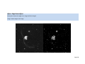
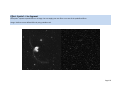
Version 1.2.2
Now Integrates with Deepsky Stacker
By Steven S. Tuma
Copyright © 2009 – All Rights Reserved
Page 1
Table of Contents
Copyright © 2009 – All Rights Reserved ....................................................................................................... 1
Revision History ........................................................................................................................................ 8
Introducing Deepsky Imaging ....................................................................................................................... 9
Welcome to Deepsky Imaging ................................................................................................................ 10
FEATURES: ............................................................................................................................................... 10
Installing the Software ............................................................................................................................ 12
System Requirements ............................................................................................................................. 12
Installation .............................................................................................................................................. 12
Terminology Used in Deepsky Imaging ................................................................................................... 13
Concepts: Bits per Pixel and Related Ideas ............................................................................................. 15
Concepts: Color Resolution and Dithering .............................................................................................. 15
Concepts: Palette Handling ..................................................................................................................... 17
Important Technical information regarding Deepsky Imaging ............................................................... 18
Hot Tips for New Users and other Notes ................................................................................................ 18
Quick Tour ............................................................................................................................................... 21
Opening an Image ................................................................................................................................... 22
Saving Images.......................................................................................................................................... 22
Printing Images ....................................................................................................................................... 23
Screen Capture........................................................................................................................................ 24
Common dialogs used in Deepsky Imaging ............................................................................................ 25
Image History Toolbar............................................................................................................................. 26
Adjusting Brightness, Contrast, and Level of your Image ....................................................................... 27
The Auto Level Feature ........................................................................................................................... 27
Aligning and Stacking Images .................................................................................................................. 30
Page 2
Interfacing to Stellacam, Mallincam, & Other Video CCD cameras ........................................................ 34
Capturing Video in Deepsky Imaging ...................................................................................................... 35
Sample of Images Taken with Stellacam III and Mallincam Cameras ..................................................... 40
Deepsky Imaging Tasks ............................................................................................................................... 43
Deepsky Imaging Tasks ........................................................................................................................... 44
File Menu ................................................................................................................................................ 44
Edit Menu................................................................................................................................................ 44
View Menu .............................................................................................................................................. 45
Animation Menu ..................................................................................................................................... 46
Image Menu ............................................................................................................................................ 46
Effects Menu ........................................................................................................................................... 50
Color Menu ............................................................................................................................................. 51
Preferences Menu................................................................................................................................... 53
Annotations Summary ............................................................................................................................ 54
Annotation Properties ............................................................................................................................ 55
Annotation Features ............................................................................................................................... 56
Annotation Tools Available ..................................................................................................................... 66
Compression Quality Factors .................................................................................................................. 86
Compression Using LEAD and JPEG Formats .......................................................................................... 88
Summary of All Supported Image File Formats ...................................................................................... 89
Effect: Gaussian Blur ............................................................................................................................ 103
Effect: Motion Blur ............................................................................................................................... 104
Effect: Zoom Blur .................................................................................................................................. 105
Effect: Radial Blur ................................................................................................................................. 106
Effect: Anti Alias ................................................................................................................................... 107
Effect: Average ...................................................................................................................................... 109
Page 3
Effect: Remove Hot Pixels .................................................................................................................... 111
Effect: Median ...................................................................................................................................... 112
Effect: Add Noise................................................................................................................................... 113
Effect: Binary Filter (Erosion) ................................................................................................................ 114
Effect: Binary Filter (Dilation)................................................................................................................ 115
Effect: Deinterlace................................................................................................................................ 116
Effect: Unsharp Mask ............................................................................................................................ 118
Effect: Sharpen ..................................................................................................................................... 119
Effect: High Pass Filter.......................................................................................................................... 120
Effect: Multiply...................................................................................................................................... 122
Effect: Subtract Background ................................................................................................................. 123
Effect: User Filter .................................................................................................................................. 125
Effect: Add Bitmaps.............................................................................................................................. 127
Effect: Stitch Bitmaps Together Into 1 image ...................................................................................... 128
Effect: Free Hand Wave ....................................................................................................................... 130
Effect: Wind.......................................................................................................................................... 131
Effect: Polar .......................................................................................................................................... 132
Effect: Zoom Wave ............................................................................................................................... 133
Effect: Radial Wave .............................................................................................................................. 134
Effect: Swirl .......................................................................................................................................... 135
Effect: Wave ......................................................................................................................................... 137
Effect: Wave Shear ............................................................................................................................... 139
Effect: Rev Effect .................................................................................................................................. 141
Effect: Ocean ........................................................................................................................................ 142
Effect: Emboss ...................................................................................................................................... 145
Effect: Punch ........................................................................................................................................ 146
Page 4
Effect: Mask Convolution (emboss) ..................................................................................................... 147
Effect: Mask Convolution (edge) .......................................................................................................... 148
Effect: Mask Convolution (splotch) ...................................................................................................... 149
Effect: Ripple ........................................................................................................................................ 150
Effect: Bending ..................................................................................................................................... 151
Effect: Cylindrical ................................................................................................................................. 152
Effect: Spherize .................................................................................................................................... 153
Effect: Plane Bend ................................................................................................................................ 155
Effect: ZigZag ........................................................................................................................................ 156
Effect: Add Shadow .............................................................................................................................. 157
Effect: Impressionist ............................................................................................................................ 160
Effect: Oilify .......................................................................................................................................... 162
Effect: Glow .......................................................................................................................................... 164
Effect: Diffuse Glow ............................................................................................................................. 166
Effect: Dry............................................................................................................................................. 168
Effect: Colored Pencil ........................................................................................................................... 169
Effect: Clouds ....................................................................................................................................... 171
Effect: Lens Flare .................................................................................................................................. 172
Effect: Pointillist ................................................................................................................................... 173
Effect: Color Replace ............................................................................................................................ 174
Effect: Glass .......................................................................................................................................... 176
Effect: Vignette .................................................................................................................................... 177
Effect: Fragment................................................................................................................................... 178
Effect: Underlay ................................................................................................................................... 180
Effect: Pixelate ..................................................................................................................................... 181
Effect: Mosaic....................................................................................................................................... 182
Page 5
Effect: Picturize .................................................................................................................................... 183
Effect: Edge Detect............................................................................................................................... 185
Effect: Smooth Edges ........................................................................................................................... 187
Effect: Edge Detect Effect .................................................................................................................... 188
Effect: Spatial - Gradient ...................................................................................................................... 190
Effect: Spatial - Laplacian ..................................................................................................................... 191
Effect: Spatial - Sobel ........................................................................................................................... 192
Effect: Spatial - Prewitt ........................................................................................................................ 193
Effect: Spatial – Shift & Difference....................................................................................................... 194
Effect: Spatial – Line Segment.............................................................................................................. 195
Effect: Annotation (Add your own text)............................................................................................... 197
Effect: Rotation .................................................................................................................................... 198
Effect: Shear ......................................................................................................................................... 199
Effect: Invert......................................................................................................................................... 201
Effect: Intensity Detect ........................................................................................................................ 202
Effect: Solarize...................................................................................................................................... 203
Effect: Posterize ................................................................................................................................... 204
Effect: Brightness/Contrast Enhancement........................................................................................... 205
Effect: Lighting Control ........................................................................................................................ 206
Effect: Hue............................................................................................................................................ 207
Effect: Tint ............................................................................................................................................ 208
Effect: Saturation ................................................................................................................................. 209
Effect: Color Balance ............................................................................................................................ 210
Effect: Convert To Colored Gray .......................................................................................................... 211
Effect: Remap Intensity ........................................................................................................................ 212
Effect: Remap Hue ............................................................................................................................... 213
Page 6
Effect: Math Functions ......................................................................................................................... 214
Effect: Histogram Equalize ................................................................................................................... 215
Effect: Histogram Contrast ................................................................................................................... 216
Page 7
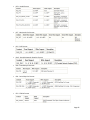
Revision History
Version 1.1 - Initial Release (March 2009)
Version 1.2.2 (May 2009)
NEW: Added AVI Capture to the capture screen as its own tab. Now you can capture to a raw AVI file
which is the preferred method for solar system imaging.
NEW: Added the ability to specify the path to where your captures get stored. It still defaults to the
MyCaptureVideo folder but now you can change that in preferences.
NEW: Added Batch Image Cleanup to the FILE menu. This lets you apply leveling, de-interlacing, and hot
pixel removal in a batch process by specifying an input and output folder. A lot faster than doing it one
at a time.
NEW: Added a stopwatch to the video capture screen for manual timings.
BUG: Opening images in Windows Vista was painfully slow. This has been corrected.
BUG: Fixed capture settings bug that would give an error when clicking OK in the settings screen.
BUG: When using a custom capture size, the size shown in the preview window sometimes would not
display at the specified size.
Page 8
Introducing Deepsky Imaging
Page 9
Welcome to Deepsky Imaging
Welcome to Deepsky Imaging. This software is designed to be used either with Deepsky Astronomy
Software or as a standalone image enhancement program. The software can be used for image
enhancement of CCD or other night sky photo’s and includes many artistic image effects that you will
also find useful for your family photos. While Deepsky Imaging is not meant to compete with the big
boys of Imaging, like Photoshop & Maxim DL, you will surely find that its many enhancement options
and file type choices will satisfy many of your image processing needs.
The software utilizes technologies from the world leading supplier of imaging toolkits, “Lead Tools”
http://www.leadtools.com/. Lead Tools toolkits are optimized for use by business, document imaging,
medical, and scientific applications. We are proud to offer so many advanced imaging capabilities as an
alternative to higher priced software. Portions of this user manual were taken from the Lead Tools
toolkit documentation as they explain some of the concepts very well.
FEATURES:
•
Interfaces directly with Deepsky Stacker for awesome pre-processing of your images.
•
Capture video from Stellacam, Mallincam, and other Composite or SVideo cameras.
o Live video preview window.
o Capture at a variety of resolutions. Uses Microsoft DirectShow.
o Supports NTSC and PAL.
o Capture to single TIF image or to uncompressed AVI file.
o Manual “Quick” capture for testing the image quality.
o Automatic sequencing
Converts AVI to a TIF image on the fly at point of capture.
Video processing lets you adjust brightness, contrast, hue, & saturation.
Auto manages saving of sequence to your computer.
Images saved use unique file naming convention.
Support for setting the interval in seconds between captures.
Support for ending the sequence after x number of captures.
Session capture history lets you easily capture additional images later.
•
Supports many different image formats such as JPG, GIF, FIT, LEAD, TIFF including multi page
images, BMP, PNG, PSP, PSD, ICO, CUR and many more.
Over 30 formats supported.
•
Deepsky Imaging supports opening 8, 16, and 32 bit FITS images including the FITS header.
Saving of FITS files is not currently supported.
•
Edit the first frame of an AVI or MPG file. Stellacam II and III owners who use video capture will
appreciate opening up a single frame. Since these cameras do their own integration, you can
Page 10
take several short exposures and use the first frame in each file and then finally stack those
images to get a nice final image.
•
Supports 12 and 16 bit grayscale images.
•
You can open nearly any image format, make changes to it using Deepsky’s enhancement tools,
and save the image either back to its original file or to a new file. Even icons can be opened!
•
Includes many image enhancement options such as : unsharp mask, guassian blur, cropping,
annotation, median, binary filter, math filters, intelligent resizing, high pass filter, background
subtraction, distort and 3D effects, Oilify, Glow, Impressionist, Wave Shear, Flip, Reverse,
Rotate, Histogram, Brightness, Contrast, Intensity, Auto Color Level, Colorize, Solarize, Posterize,
Lighting, Hue, Saturation, Remap Intensity, Spatial Filters, and many others.
•
Unique history toolbar keeps copies of all your changes so you can go back to prior images.
•
Convert an image from one file format to another.
•
Increase and decrease color depth.
•
Create simple animations by combining images together.
•
Color Separation and Color Merge tools.
•
Web tuner lets you play with JPEG, GIF, and PNG so that you can see the effect of file size and
compression differences before saving the image.
•
Region processing lets you select a portion of the image and perform processing on just that
region.
•
Supports TWAIN scanners.
•
Thumbnail image browser lets you see a group of images in a folder, then selectively load the
images into Deepsky Imaging.
•
Full drag and drop support. Easily load any number of images by simply dragging them from
Windows explorer.
•
HTML Image Map creator.
•
Advanced screen capture capabilities.
•
Sophisticated Printing and Preview capabilities.
•
Pan and Magnify tools included let you move around large images effortlessly, and magnify
portions using the mouse.
•
Deepsky Imaging remembers the last folder you used to open a file and takes you right back
there the next time.
Page 11
•
Customizable toolbars let you hide or view them easily.
Installing the Software
System Requirements
•
Windows 98, NT, 2000, ME, XP, 2003 Server, Vista 32 and 64 bit versions, Windows 7 Beta –
Windows 95 is no longer supported but Deepsky Imaging may still work.
•
A minimum of 512 megabytes is recommended. The more memory you have, the better.
•
Screen resolution of at least 1024x768. You can still run the software at lower resolutions but
some of the screen elements will be pushed off the screen.
•
For image capture, you must have a Capture card compatible with Microsoft DirectShow.
Installation
•
Run the Setup.exe to start the process.
•
Answer all of the default prompts.
•
When finished, run the software.
IMPORTANT NOTES:
1. If you are using Windows Vista or Windows 7 and encounter any installation problems, please
make sure you run the setup.exe with Administrator permissions.
2. It’s highly recommended that you have your Windows operating system up to date with patches
and security fixes. You can run Windows Update manually by visiting the Microsoft website at
http://www.windowsupdate.com
3. Saving of captures may not work properly in Windows Vista if you use the default
MyVideoCapture folder in the Deepsky Imaging folder. You can change this location in
preferences or turn off Vista's UAC.
Before we get started discussing the particulars, you may be interested in reading about some key
terminology and concepts after you install the software.
Page 12
Terminology Used in Deepsky Imaging
Annotations
Annotations, which are based on vectored drawing functions, are associated with an image only
as an overlay of the displayed image. Use annotations to mark up your image without actually
damaging the image. The individual annotation objects are stored in a separate file with the
same name as the image, but with a file extension of .ANN.
Bias Frame
This is a zero length exposure taken with a CCD camera with the shutter closed. It is used to
compensate for pixel specific offsets in the CCD chip and electronics.
Bitmap
A bitmap is the image data in memory.
CCD
This stands for Charge-Coupled Device and contains an array of light sensitive pixels.
Deepsky Stacker
This is an awesome freeware image stacking program that interfaces directly with Deepsky
Imaging. The software is free to download and should be used if you are stacking images.
http://deepskystacker.free.fr/english/index.html
Dark Frame
This is an exposure taken using a CCD camera with the shutter closed. The length of the
exposure should match the length of normal exposures taken. Dark frames are used to help
compensate for noise in the CCD camera ultimately resulting in better images when processed.
FITS
FITS stands for Flexible Image Transport System. This is the standard image format used by
astronomers worldwide. FITS supports including a data header along with the image that
contains information about the observation.
Flat Field Frame
This is an exposure taken of an evenly illuminated source. These frames are also used to
compensate for noise and other artifacts.
Image History Toolbar
The toolbar used to record all image processing tasks so that the user can reload the image at
any point in the process.
Page 13
Lossy Compression
A lossy compression method is one where compressing data and then decompressing it
retrieves data that may well be different from the original, but is close enough to be useful in
some way. JPEG files use this method. Typically you want to process images in their non
compressed form and save them to formats such as JPEG when you are all done with them.
Magnifying Glass
This magnifying glass provides a means of "zooming in" on the image loaded into the image.
Use the "Magnifying Glass" if you want to:
• Control the painting options for the zoomed display.
• Set the contrast, gamma and intensity for the zoomed area.
Pan Window
The Pan Window is a small window which will display a scaled view of a bitmap, which is also
being displayed in the Main Control's window at a size that would require scrolling. The Pan
Window will maintain the image’s aspect ratio. In the Pan Window, a colored Pan Rect will be
displayed to indicate the portion of the image currently being displayed in the main window.
When a user clicks inside the Pan Window and moves the mouse, while holding down the
button, the Pan Rect will move with the mouse pointer.
Region
A bitmap region is an area of interest within an image. A bitmap can have only one region at a
time, but the region can be complex, including, for example, multiple noncontiguous shapes.
Deepsky Imaging allows you to perform most filtering and other enhancement tasks on the
selected region.
Zoom View
This Zoom View provides a means of "zooming in" on the image loaded into the window to
which it is attached. As the source rectangle is moved over an image, the zoomed - in view also
changes. This is similar to having multiple Magnifying Glasses on the same source image.
Use the "Zoom View" if you want to:
• display one or more zoomed views for a single displayed image
• display an annotation in addition to the zoomed view
• display callout lines
Note that a "magnifying glass" is also available that can be attached to a window handle.
Use the "Magnifying Glass" if you want to:
• control the painting options for the zoomed display.
• set the contrast, gamma and intensity for the zoomed area
Page 14
Concepts: Bits per Pixel and Related Ideas
The terminology for image formats can be confusing because there are often several ways of describing
the same format. This topic explains what the terms mean.
If an image is 24 bits per pixel, it is also called a 24-bit image, a true color image, or a 16M color image.
Sixteen million is roughly the number of different colors that can be represented by 24 bits, where there
are 8 bits for each of the red, green, and blue (RGB) values.
A 32-bit image is a specialized true-color format used in image files, where the extra byte carries
information that is either converted or ignored when the file is loaded. The extra byte is used for an
additional color plane in CMYK files, which are specialized files for color printing. In that case, the
software, by default, converts the values to 24-bit RGB values when loading the image. The additional
byte may also be used for an Alpha channel, which carries extra information such as a transparency
indicator.
If an image is 16 bits per pixel, it is also called a 16-bit image, a high color image, or a 32K color image.
Thirty-two thousand is roughly the number of different colors that can be represented by 16 bits, where
there are 5 bits for each of the red, green, and blue values. (Devices that specify 64K color support are
also referring to 16-bit images, but they are counting the left-over bit.)
If an image is 8 bits per pixel, it is also called an 8-bit image or a 256-color image. Two hundred fifty-six is
the number of different colors that can be achieved by using the image data as 8-bit indexes to an array
of colors called a palette.
If an image is 4 bits per pixel, it is also called a 4-bit image or a 16-color image. Sixteen is the number of
different colors that can be achieved by using the image data as 4-bit indexes to a palette.
If an image is 1 bit per pixel, it is also called a 1-bit image, a black and white image, a 2-color image, or a
bitonal image. Two is the number of different colors that can be achieved by using the image data as 1bit indexes to a palette. The palette can contain colors other than black and white, although black and
white are most common.
If an image is grayscale, its red, green, and blue values are all the same, and the values are incremented
from the lowest to the highest. For example, an 8-bit grayscale image has 256 shades of gray, with
values from 0 to 255.
Concepts: Color Resolution and Dithering
Color resolution (also called color depth) refers to the number of possible colors in an image, as
determined by the bits-per-pixel. If an image in your computer is loaded from a FAX scanner or received
as a FAX transmission, it is a black-and-white (1-bit) image. If it is loaded from a color scanner or a JPEG
Page 15
file, it can have 16 million colors. If it is loaded from a GIF file, it is likely to have 256 colors. There are
many possibilities, ranging from two colors to over 16 million.
This software lets you manipulate an image and display it on any Windows-compatible device,
regardless of the image's color resolution. Therefore, in most cases you can load, display, modify, and
save an image without ever changing its color resolution. Nevertheless, in some cases you may need to
increase or decrease the color resolution. Here are some examples:
•
Suppose you need to load a large 24-bit image on a computer that does not have much
memory. You can conserve memory by loading it as an 8-bit image. Then, if you were using
an 8-bit display device, you would not see any difference in the quality of the image. Of
course, there would be some loss of quality on a 24-bit display device, and the loss would
be permanent if you then saved the image in the same file.
•
Suppose you want to save an image in a different file format. If the new file format does not
support the original color resolution, you can specify a different color resolution when you
save the image.
•
Suppose you want to combine one 8-bit image with another one. To combine two images,
they must have the same color resolution, and if they are less than 16 bits per pixel, they
must use the same palette. The simplest solution is to convert both images to 24 bits per
pixel before combining them. Then, if necessary, you can reduce the color resolution of the
combined
image.
Whenever you reduce an image's color resolution to 8 bits per pixel or less, a dithering method comes
into play. One alternative is to use a nearest-color match (no dithering), which means that the color of
each pixel is changed to the palette color that most closely matches it. If the original image contains
subtle color details, the result of a nearest-color match may have large blotches of color that are not
very pleasing.
Dithering methods create the appearance of more subtle shades by mixing in pixels of different colors.
This is similar to the way newspaper pictures produce the appearance of shades of gray, even though
the only actual colors are black and white.
Ordered dithering is the fastest method. It is the default dithering method when painting to a display
device that is 256 colors or less. Ordered dithering takes advantage of the fact that the colors in most
palettes are ordered so that similar shades are next to each other in the palette. This method avoids
blotches of color by adding to or subtracting from the nearest-color value of each pixel to ensure that
adjacent pixels do not have exactly the same color. (If the colors in the palette are not ordered, the
results are not good.)
All of the other dithering methods in the software use error-diffusion algorithms. In error diffusion, the
error is the difference between the original pixel color and the nearest match, and diffusion of this error
is what the algorithm accomplishes. Floyd-Steinberg is a high-quality, fast error-diffusion method. It is
the default method that the software uses if you reduce the color resolution when loading or saving an
image, or if you specify error diffusion as the dithering method when painting to a display device that is
256 colors or less.
Page 16
If you use a function to change the color resolution of a bitmap in memory, you can choose from a list of
possible dithering methods. All of the alternative error-diffusion methods are slower than FloydSteinberg, and the quality may or may not be better, depending on the original image, and depending
on whether the resulting image is to be displayed or printed. Choosing an alternative dithering method
is a subjective, trial-and-error decision. Stevenson and Arce dithering, the slowest of the alternatives, is
most likely to produce a higher quality result.
There is a family of Reference Output Medium Metric (ROMM) BGR Color encodings that is a wideprimary output-referred extended color-gamut BGR color encoding. These encodings are used by digital
still picture imaging systems to manipulate, store, transmit, display and print digital images. Unlike sRGB
color encoding, the range of colors is not limited to those colors that can be displayed on a CRT monitor,
and unlike e-sRGB, these encodings do not use negative RGB colorimetry co-ordinates.
ROMM color order can be used only with 24 or 48-bit bitmaps and is supported by the CMP/JPEG/Exif
JPEG/JTIF/TIFF CMP file formats. There are colors that can be represented in RGB, but not in ROMM.
Conversely, there are colors that can be represented in ROMM that cannot be represented in RGB. If
you convert from one to the other you lose the colors that can be represented only in one of the
colorspaces.
Concepts: Palette Handling
Any image that is 8 bits per pixel or less must have a palette. The palette is an array that contains the
colors for displaying the image. The pixel values are indexes into the array. An image can have its own
unique palette or it can share a common fixed palette. In either case, every bitmap in memory that is 8
bits per pixel or less has its own copy of a palette (even if it is a common fixed palette).
One way for a bitmap to have a unique palette is to load an image from a file that is 8 bits per pixel or
less. In that case, the file contains a palette for the image, and you can assume that the palette is
unique. By default, the software loads the palette that is stored in the file and associates it with the
bitmap in memory.
Another way for a bitmap to get a unique palette is to create the palette. For example, if you reduce a
24-bit image to 8 bits per pixel, you can let the software create an optimized palette for the image.
By using a unique, optimized palette, you get the best possible image quality, but there is a drawback.
When a display device uses a palette (for example, when it is in 256-color mode), it can only use one
palette at a time to display colors. Therefore, if you are displaying more than one image at the same
time, the current image may look perfect, while all of the others look bad, because they are mapped to
the wrong palette. This is called palette shift.
Using a fixed palette solves these palette-shift problems. The best approach is to specify the fixed
palette as a display option. Then, the software remaps each image to the fixed palette when it is
Page 17
displayed, without disturbing the individual image's palette. (When displaying 16-, 24-, or 32-bit images
on a device with 256 colors or less, the software always uses the fixed palette.)
Alternatively, you can use a color resolution function to specify a fixed palette for each individual image.
But then, when you save the image to a file, the fixed palette is saved in the file, and any unique palette
information is lost.
Important Technical information regarding Deepsky Imaging
•
Deepsky Imaging can be used standalone or with the upcoming version of Deepsky Astronomy
Software.
•
This software utilizes Microsoft COM technologies. Future versions will use .NET.
•
This software uses the world class imaging toolkit from Lead Tools version 14.5. Imaging is a
tough area to write programs for so picking a high quality imaging toolkit from Lead Tools has
simplified and reduced software development time for Deepsky Imaging. Programmers may be
interested in visiting their website at http://www.leadtools.com/ to learn more about their
toolkits.
Hot Tips for New Users and other Notes
•
HOT TIP: Version 1.2.2 now supports capturing directly to an AVI file. This is the preferred
method for capturing solar system images.
•
HOT TIP: Download and install Deepsky Stacker, a freeware stacking program that interfaces
with Deepsky Imaging. Before using it via Deepsky Imaging, make sure you set all settings in
Deepsky Stacker since Deepsky Imaging uses those settings.
http://deepskystacker.free.fr/english/index.html
•
HOT TIP: If you are running a 64 bit Windows operating system and keep getting a message that
Deepsky Stacker is not installed when you know it is, just go to OPTIONS under preferences and
select the path to the DeepskyStackerCL.exe file.
•
If an image is larger than the screen window, you can PAN the image by left clicking and holding
the mouse button down while you drag the mouse. The toolbar at the top includes a FIT and
100% zoom factors to simplify working with large images.
•
Use the reopen option on the FILE menu to reopen past images.
Page 18
•
Don’t have a screen capture utility like Snagit? Use the advanced capture option on the FILE
menu instead. It allows for capturing full screens, windows, and even regions.
•
Select the eyeglass icon
on the left toolbar to enable magnify mode. Now when you left
click, a little zoom window will follow your mouse as you move it.
•
Deepsky Imaging includes a very robust annotation feature that lets you add text and other
markup to your images without actually affecting the images. You can add hotspots as well that
link to web sites. There’s a lot of functionality there if you are interested in it.
•
You can open an AVI and MPEG video file to retrieve the first frame of the image. Unlock other
software, only one image will be presented to you. This is useful if you are a Stellacam user who
captures integrated video images with the Stellacam II or III. I use this method myself and it
saves a lot of time.
•
This software will read 8, 16, and 32 bit FITS images. Currently SAVE support is disabled for FITS
but this will be added in the future. When a FITS image is shown on screen, you can click the
FITS header icon
to view information about the image.
•
Use the Blinker feature to see if any movement can be detected in your images that you take
over time.
•
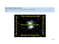
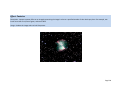
Deepsky Imaging includes over 100 imaging effects that can be used to artistically enhance your
images. The opening splash screen used the Lens Flare effect under the Effects Artistic menu.
The end of this manual includes many examples showing you what these effects will do to your
images.
•
You have the ability to preview all effect changes prior to applying them to your image.
•
The “Auto Level” button on the main toolbar can be used to automatically adjust the brightness
of the image. To see how this works, open the sample image orion-16.fits . When it appears on
the screen, the image appears all white. Now click the “Auto Level” toolbar button and the
image will come into view. I’ve noticed that for many FITS images that “Auto Level” is needed to
see the image.
•
One of my favorite options in the software is called “Remap Intensity” which can be found under
the Color menu Transform. Here you can drag the line on the graph to change the intensity
and brightness of the image.
•
If you notice hot pixels in your image, you can run the “Remove Hot Pixels” function under the
Effects Noise menu. Run it more than once to remove more pixels.
•
Deepsky Imaging can also be used to enhance your non astronomy images as well. There are
many tools like red-eye reduction and stitch images available for you to use.
Page 19
Touring Deepsky Imaging
Page 20
Quick Tour
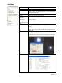
Deepsky Imaging utilizes an MDI application similar to Microsoft Word and other popular applications.
This simply allows the user to open as many child windows as they want, making it easy to load many
different images in the software at the same time. The software consists of several toolbars that
contain commonly used functions and are customizable. The image history toolbar is special. It saves a
copy of the image to your hard disk prior to performing some enhancement function on it. Thumbnails
of these saved images show up in this toolbar and you can click one to load that image back into the
editor. Each toolbar icon will display a tooltip when you hover over it which tells you what the icon is
used for.
The menu bar at the top contains all of the features you will use in the software. The most popular
features have been also placed on one of the toolbars to make it more accessible. Finally, the status
bar at the bottom of the screen will always display useful information about the currently selected
image showing on the screen. Here you can see the image size, bit depth, zoom %, size and name of the
image.
Page 21
Opening an Image
For the most part, Deepsky Imaging is easy to use. It functions similar to other image programs you may
have used in the past. Let’s examine the four ways we can open an image using Deepsky Imaging.
1. Select FILE OPEN or click the Open an Image Icon on the toolbar.
2. Drag any image(s) from Windows Explorer into the Deepsky Imaging window.
3. Selet FILE BROWSE or click the BROWSE toolbar button to select a folder on your system and
have thumbnail images shown for each image. To open the image, just click the thumbnail. You
can leave the browser open while you work in case you want to open another image.
4. The next version of Deepsky Astronomy Software will interface directly to Deepsky Imaging.
While using Deepsky Astronomy Software, you will be able to double click images you see in the
software and have them shown in Deepsky Imaging.
Saving Images
Once you have an image open, you can save it at any time using the SAVE or SAVE AS buttons. For a few
image formats like JPEG, you will only be able to do a SAVE AS so that you don’t save over the original
image. Since JPEG uses compression, every time you save the image, quality is lost. If you click the
SAVE icon by mistake, don’t worry, you will be prompted to save it to a different filename.
The Convert option on the FILE menu gives you extensive capability to save your image into another file
format, utilizing special attributes of that format. For example, if you convert a file to JPEG, you have
the option of specifying bit depth, sub type, quality factor, and other options.
The Convert option even lets you specify a folder to do a batch conversion of all of the images in that
folder. You have the ability to take multiple format images in one folder, and convert them to a single
format placing them in another folder. You can even resize them or rotate them.
Page 22
Printing Images
Printing images couldn’t be easier in Deepsky Imaging. Once you have an image ready to print, you can
either print it right away or you can preview it first as shown below.
Page 23
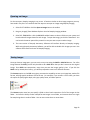
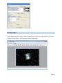
Screen Capture
Deepsky includes some pretty awesome screen capture capabilities. You can quickly capture the screen
by going to FILE CAPTURE SCREEN. Deepsky Imaging will minimize its own window and then take a
full screenshot of whatever is on your screen, loading the captured image into Deepsky Imaging. For
finer control, use the Advanced Capture located on the FILE menu. This easy to use, yet flexible
capture utility will let you capture a screen in a multitude of ways.
IMPORTANT: After clicking Capture, make sure you HIT F11 to take the screenshot.
•
Full Screen – captures your entire computer screen.
•
Wall Paper – captures your desktop wallpaper without including your icons
•
Active Window – captures the active window (the one with focus)
•
Active Client – captures the active client (without the window’s title bar)
•
Region Capture – uses the selected option to capture the screen in the shape you have selected.
For example, if you select Region Free Hand you can use the mouse to draw around an object
on the screen. These options give you a lot of flexibility.
NOTE: For Region capture, after you click the capture key in Deepsky Imaging, find the area you want to
select and press F11. Once F11 is pressed, you will be able to highlight the region you want to capture.
When you release the mouse button, the image will be transferred back into Deepsky Imaging.
Page 24
Common dialogs used in Deepsky Imaging
Before we take off looking at all of the options Deepsky Imaging gives you, I want to briefly touch on
dialog screens you will see when using the software. These dialogs give you the opportunity to apply
some effect to the preview image prior to applying the effect to the main image. A simple dialog screen
such as the “Brightness” adjustment dialog provides a simple slider to adjust the brightness. If you click
OK, the effect will be applied to your image.
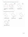
Other dialog screens may have additional options. For instance, the “Add Shadow” screen lets you
create a 3D effect on the image which mimics shadows.
Page 25
Each screen will have controls that let you adjust the size of the image. The common controls include:
Scale Mode – you can adjust the scale mode (A) to view the image at a normal size, or view it so that the
entire image fits the preview screen. If the image is larger than the preview screen and you have 1:1
set, you can use the mouse to drag the image around until you find the point of interest you are looking
at.
Reset Image – this button reloads the preview screen with the original image without any of your
changes. You will find this option useful as you try different parameters on the dialog as you experiment
with different effects.
OK – click this button to apply your changes to your main image. If you make a mistake and want to
undo the operation, simply click the UNDO button on the toolbar. This button lets you go back one
processing task. If you want to go back further that that, you should use the Image History Toolbar.
Image History Toolbar
The image history toolbar keeps track of all your changes to an image. You can use it as kind of a super
UNDO function, to revert back to earlier versions of your images. Prior to making changes to an image,
Deepsky will make a copy of your image, placing it in the HISTORY folder. If you make a mistake on an
image, you can find a suitable copy of the image in the history toolbar, and click the thumbnail to load
the image back into Deepsky Imaging. Keep in mind, that the image will be loaded into its own new
window, so your other image will still be there unless you close it.
All of the images in the history toolbar can be left there indefinitely as long as you don’t run out of disk
space. What you may want to do is select the CLEAR HISTORY AT START OF PROGRAM option located
on the Preferences menu. When you have this selected, each time you start Deepsky Imaging, all of the
images in the history folder will be deleted. You can also clear the history toolbar via the “Clear History”
button on the toolbar. This gives you a little more control over when and when not to clear the history.
Page 26
Special Note regarding the history Toolbar:
The images in the toolbar are saved as JPG files (with no compression) even if you are working in
another image format. Please keep this in mind if you reopen an image from the history toolbar. Also, if
you notice that Deepsky Imaging is taking longer to start up, then clear the image history toolbar.
Adjusting Brightness, Contrast, and Level of your Image
One of the most basic image processing tasks is adjusting the brightness, contrast, and intensity of an
image. Deepsky provides several tools to do this. These options are located on the ADJUST
menu which is located on the COLOR menu. The Brightness and Contrast options let you adjust them
independently whereas the Brightness Contrast Enhancement option combines these tools. A variety
of other tools like Gama, Saturation, and Hue let you further control all aspects of the image’s
brightness and color.
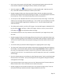
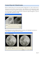
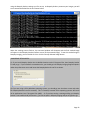
The Auto Level Feature
You can use the “Auto Level” feature to automatically adjust the Level, Contrast, and Intensity of the
image. There are several tools available to accomplish this. A quick leveling button is displayed on the
toolbar and is configured under Preferences Program Options.
Page 27
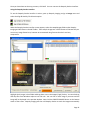
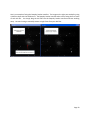
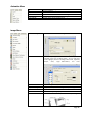
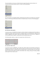
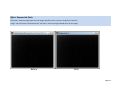
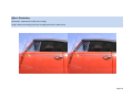
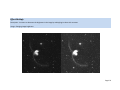
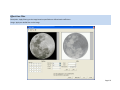
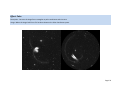
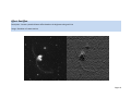
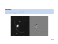
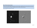
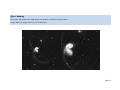
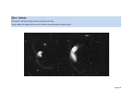
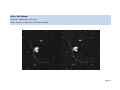
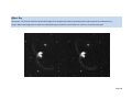
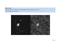
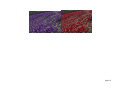
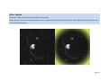
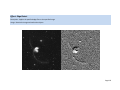
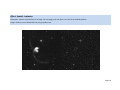
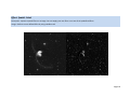
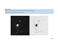
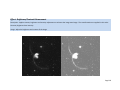
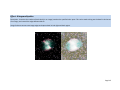
To see how this feature works, open up the m65_cal.fit file located in the sample images folder. You
should see the image as it appears below (left). Now, click the Auto Level button on the toolbar. The
details of the image will become visible as shown in the right image.
You can have Deepsky Imaging auto level the image on Open by clicking the checkbox in Program
Options. You can also configure the black and white level to adjust the amount of leveling that will be
used.
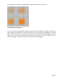
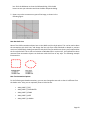
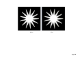
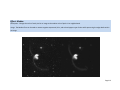
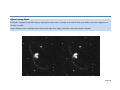
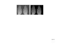
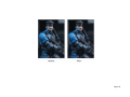
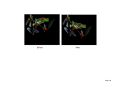
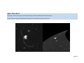
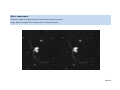
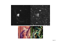
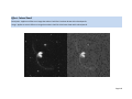
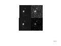
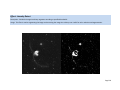
Not all images will require leveling all of the time. For convenience, a comparison tool is also available
on the Color menu named “Auto Color Level Selection”. This tool displays four images that you can
Page 28
review to see which one looks best. You can adjust the black and white settings and select the image
you want to use.
Page 29
Aligning and Stacking Images
Taking multiple short exposure images of your favorite deep sky object is common practice these days in
order to average out the noise in each individual image, resulting in a better quality image. Deepsky
Imaging provides an excellent interface into Deepsky Stacker which allows you to take advantage of all
of its stacking features. Before using this interface it is important to go into Deepsky Stacker and set
your settings because Deepsky Stacker uses those settings when you are in the Deepsky Stacker
Interface. Make sure your settings are saved.
Deepsky Stacker can be downloaded free: http://deepskystacker.free.fr
Deepsky Stacker is an awesome program for stacking images. If you are new to imaging, you might not
know which settings to use. The best thing to do is to learn how Deepsky Stacker works and review its
help manual. When I first started using Deepsky Stacker I was up and running stacking images in 15
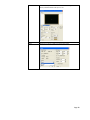
minutes or so. Go to the options area in Deepsky Stacker and look at the various options. Start with
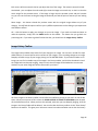
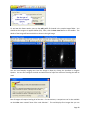
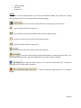
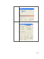
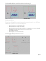
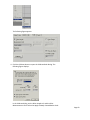
SETTINGS as shown below. I went to the LIGHT tab and selected MEDIAN for the stacking mode.
Now go to the OUTPUT tab (you can hit the right arrow to see more tabs) and make sure the OUTPUT
FILE NAME (show highlighted below) is set to Autosave.tif. Deepsky Imaging expects the final image
from Deepsky Stacker to be called this name.
Page 30
Once you have them set the way you want, click SAVE. You can now use the Deepsky Stacker Interface.
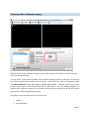
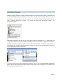
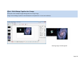
Using the Deepsky Stacker Interface
To see the Deepsky Stacker Interface in action, open up Deepsky Imaging and go to Image menu and
select the Align & Stack by File Selection option:
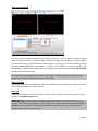
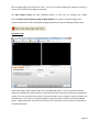
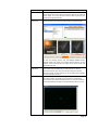
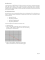
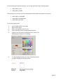
When the Deepsky Stacker Interface screen appears, select the sampleimages folder under Deepsky
Imaging and drill down to the M17 folder. These sample images are in JPEG format to illustrate that you
can use any image format here, however we recommend using formats that don’t use lossy
compression.
Highlight the 4 images in that folder and drag them over to the Images (Light) list box. You can also drag
and drop files from Windows explorer into each tab. You can click on each image if you want and the
image will be displayed in the preview window. Now click the PROCESS IMAGES button at the bottom
center of the screen. Deepsky Imaging will then call Deepsky Stacker to stack the images automatically
Page 31
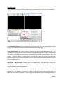
using the Deepsky Stacker settings you first set up. As Deepsky Stacker processes your images, you will
see a command window like the one shown below.
When the stacking process finishes, the command window will disappear and the final stacked image
will appear in the Deepsky Stacker Interface screen (final processed image). To use this stacked image in
Deepsky Imaging, you can double click it or click the Accept Selected Image button.
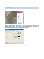
IMPORTANT SETUP NOTES:
(1) If you install Deepsky Stacker into its default location under C:\Program Files, then Deepsky Stacker
is ready to go. If you installed it somewhere else, you should go into Deepsky Imaging Program Options
under the preferences menu and locate the DeepskyStackerCL.exe file as shown.
(2) If you are using a 64 bit Windows operating system, you should go into the above screen and select
the DeepskyStackerCL.exe file manually. This is necessary because 64 bit operating systems will install
32 bit applications into C:\Program Files (x86)\ . So if you keep seeing a message telling you Deepsky
Stacker is not installed and you know it is, just set the path in Deepsky Imaging and you are good to go.
Page 32
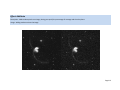
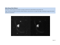
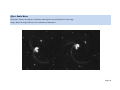
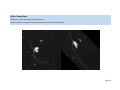
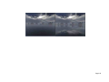
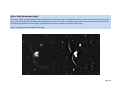
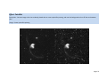
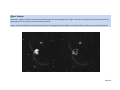
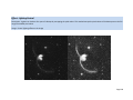
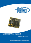
Here’s an example of using the Deepsky Stacker Interface. The image on the right was stacked by using
4 AVI files taken with the Stellacam III. The Deepsky Stacker Interface takes care of using the first frame
of each AVI file. You simply drag the AVI files into the Deepsky Stacker Interface and start stacking
away. No more having to manually extract a single frame from your AVI files.
Page 33
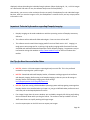
Interfacing to Stellacam, Mallincam, & Other Video CCD cameras
As a newcomer to the world of CCD imaging, I started out using a Stellacam II and then III video cameras
for recording my images. These cameras are good for taking short exposure integrated videos of deep
sky objects, but you have to capture the video using a capture card and save the video as an AVI file.
If you own a Stellacam, http://www.astrovid.com/further_details.php?pid=3306 or a Mallincam,
http://mallincam.tripod.com/ you will know that these cameras are integrating cameras that
accumulate frames as the image is being taken. Once the image is complete, you can capture the image
as an AVI file and convert it into a TIF or other bitmap. Since the camera only outputs video you will
need to capture it using a USB capture card that connects the camera to the USB capture card.
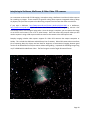
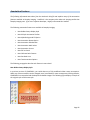
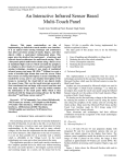
Deepsky Imaging includes video capture support for Video CCD cameras that output composite or
SVideo. This includes the Stellacam and Mallincam line of cameras. Video CCD cameras do an excellent
job of capturing deep sky objects and are ideal for beginners of astronomical imaging because good
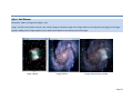
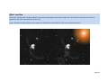
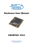
results can be obtained on an alt/azm mount without auto guiding. I captured the following image using
my 8” LX200R with the Mallincam Color. The final image is a stack of eight 28 second frames.
Page 34
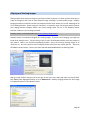
Capturing Video in Deepsky Imaging
TIP: New to this version of Deepsky Imaging, you can either capture your video as a single TIF image or
as an uncompressed AVI file.
If you go the TIF route, capturing video is easy in Deepsky Imaging because it takes care of converting
the raw AVI image from the camera into a TIF image. It then stores the result in an organized folder,
called MyVideoCapture, under the Deepsky Imaging program folder. Windows Vista users may have
trouble saving captures to this folder unless UAC is turned off or they run Deepsky Imaging as an
Administrator. New to this version, you can specify a different path in preferences so that the captures
get stored in a folder that Windows Vista likes.
The capture screen is broken down into a couple areas.
•
•
Toolbar
Preview Window
Page 35
•
•
•
Capture Window
Setup Tab
Capture Tab
Toolbar
The toolbar is used to specify whether to scale the video preview window, fit the video to it, change
video settings, and return a test capture back to Deepsky Imaging.
This puts you in full screen mode to aid in focusing or to view live video.
Sets the video preview at its actual size.
Fits the video to the preview window so that the entire image is shown.
Stretches the video to take up the entire preview window.
Displays the video double its normal size.
Use this button to manually time your exposures.
Sets various video settings including video decoder, processing, & video source. The
screen that shows when this is selected is dependent on your video capture card driver.
Sets additional video settings. The screen that shows when this is selected is
dependent on your video capture card driver.
Takes the captured image and returns it to Deepsky
Imaging.
Page 36
Video Preview Window
The video preview window is where the live video will be shown. You can view the video in Normal
mode or Full Screen mode. Full Screen mode is useful for focusing or for viewing live images; however
you will need to return to Normal mode to capture images. You can go into Full Screen mode by clicking
the FULL SCREEN MODE icon on the toolbar. To return to Normal Mode, you can click the EXIT FULL
SCREEN button. While in either mode, you can also adjust some video parameters under Video Settings
to brighten or darken the image.
TIP: Use Full Screen mode to help achieve focus or to view live video. Clicking the “Display the video
double its normal size” icon will show an even larger image.
Capture Window
The window will show you a single frame capture of the object you are imaging. This image is the result
of the integrated exposure from the camera.
Setup Tab
The Setup tab is where you select your capture device, capture size, perform a manual “quick” capture,
and clear the MyVideoCapture folder.
IMPORTANT NOTE : Not all capture sizes will work with your camera. If one doesn’t work for you, try
another. If none work, you can put in a custom size like 520 x 280 at the bottom and then click APPLY.
640x480 seems to work well for Stellacam and Mallincam video cameras. Other cameras such as
webcams may require the custom setting.
Page 37
Still Capture Tab
The still capture tab is where you will be capturing your images as TIF files, either 1 at a time manually,
or using the automated capture process.
The object being imaged text box is where you put the name and other info about the object being
imaged. This information will be a part of the file name for each saved image.
Session Capture History will contain a history of objects that you have imaged during this session. You
can go back later and select one from the list and take additional images and they will be stored in the
same folder. For example, let’s say you take 5 exposures of M17 and the name you gave is “M17 – 30
seconds”. You then move on to another object. If you wanted to later in your observing session take
additional images of M17, you can select M17 from the history list and all new images will be stored in
the same folder as before.
Single Frame – Manual Capture is used to capture 1 integrated frame. The image will be saved to the
folder name you indicate in “Set Object Being Imaged”. You might use this option if using the red switch
on the Stellacam III to control the exposure.
Capture a series of images will enable you to image the same object at different intervals all
automatically. For example, you can enter 30 for the interval and 10 for the “Stop after Count” to
capture 10 images of 30 seconds each. Once captured you would later stack the 10 images to achieve a
Page 38
final averaged image that contains less noise. You can also control stopping the sequence manually, if
you are not sure how many images you will take.
The Goto Capture Folder will open Windows Explorer so that you can manage your images.
Click the Return Current Captured Image to Main Window at any point to send the image in the
preview window back to the main Deepsky Imaging window by clicking the following toolbar button:
AVI Capture Tab
Use the AVI capture tab to capture video as an uncompressed AVI file. This is the preferred capture
method for imaging solar system objects since you will most likely need many frames to get a good final
image. Like in the still capture tab, specify a name of the object you are imaging. This will be used in the
saved filename. Then enter in an exposure length in either seconds or minutes, and click the EXPOSE
button. Images captured in this manner will eat up a lot of disk space since the capture is being done in
uncompressed mode.
Page 39
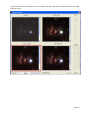
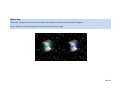
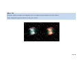
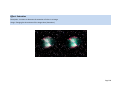
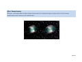
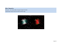
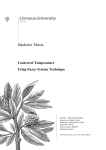
Sample of Images Taken with Stellacam III and Mallincam Cameras
Page 40
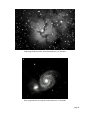
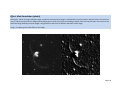
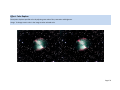
M20 using Stellacam III four 30 second exposures 12” RCX 400
M51 using Stellacam III single 60 second exposure 12” RCX 400
Page 41
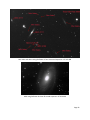
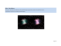
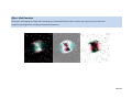
NGC 4111 and others using Stellacam III four 30 second exposures 12” RCX 400
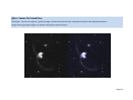
M81 using Stellacam III three 45 second exposures 12” RCX 400
Page 42
Deepsky Imaging Tasks
Page 43
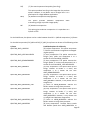
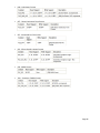
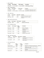
Deepsky Imaging Tasks
The following information gives you a summary of all of the options and features you have available to
you in the software.
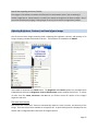
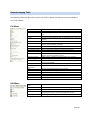
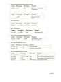
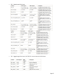
File Menu
New
Open
Reopen
Save
Save As
Close Current Image
Convert
Browse
Batch Image Cleanup
Stitch multiple images
Capture Screen
Advanced Capture
Select Your Scanner
Scan an Image
Web Tuner
HTML Map Creator
File
Format
Associations
Print
Print Stitched Images
Print Preview
Reset Imaging Prefer.
Reset Toolbars
Exit
Edit Menu
Copy Image to Clip
board
Paste
Undo
Select Region
Cancel Region
Start a new blank image according to the dimensions you choose.
Open an image from your local or network drive
Opens an image that was previously opened. This is a recent Image
list.
Save the currently displayed image to disk.
Save the currently displayed image to disk allowing you to select the
format.
Closes the current window
Image conversion program that converts images from one format to
another. Batch conversion is available.
Browse a folder of images displaying the results in a thumbnail view.
Processes a series of images for leveling, removing hot pixels, etc.
Stitch multiple images together to make one larger image.
Captures the current screen.
Captures the screen in a variety of ways including full, region, &
desktop. Use F11 to initiate the capture.
Selects a twain compatible scanner attached to your computer
Scans an image or document into a new window in Deepsky Imaging
Examine the effects of compression on an image so that you can
optimize it for the Web.
Allows you to create an HTML map of the image.
Associates file formats with Deepsky Imaging.
Print the image displayed in the current window.
Prints several stitched images.
Preview the image before printing it.
Resets all preferences in Deepsky Imaging to their default values.
Resets the toolbars back to default settings.
Close Deepsky Imaging.
Copies the current image to the Windows clipboard.
Pastes an image into a new window in Deepsky Imaging.
Cancels the last operation.
Selects a region of the image. Subsequent image processing tasks will
be applied to that region until the Cancel Region is selected.
Cancels region processing.
Page 44
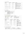
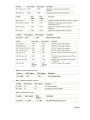
View Menu
Normal
Zoom
Fit Image to Window
Fit Sides to Window
Stretch Image to
Window
Snap Window to Full
Image Size
Snap Window to
Current View
First Page, Previous
Page, Next Page, Last
Page
Pan Window
Magnifying Glass
Zoom View
View FITS header
Displays the image at its actual size.
Lets you Zoom into the image.
Fits the image to the current window.
The largest possible width or height is set to the control's client area
width or height. The remaining dimension is set proportionally to
maintain the aspect ratio.
Width is the control's client area width. Height is the client area
height. The aspect ratio is not preserved.
Makes the size of the window equal to the image size.
Makes the size of the window equal to the image size the image is
currently scaled at.
Used for navigation in multi paged images.
Displays a small pop up window showing the entire image with a
rectangle of the current view that can be used to pan around the full
image.
Makes the mouse pointer appear as a magnifying glass. Left click to
zoom in at the mouse position. Configurable in Program Options in
Preferences.
Lets you create 1 or more magnified windows that can be dragged
around the screen like with Pan Window. Zoom view is fully
configurable and multiple zoom views can be active on a single image.
View header information of the currently shown FITS image
Page 45
Animation Menu
Create
Go
Loop
Optimize Colors
Screen Settings
Frame Settings
Lets you specify the images for the animation
Runs the animation.
Turns on LOOPING to make the animation run over and over.
Specifies the color resolution to use for the image.
Specifies screen settings such as width and height to use.
Specifies settings for the animation frame.
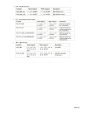
Image Menu
Add Text to Image
Easiest method to add text to an image.
Annotation
This is a fully fledged annotation module that lets you have
complete control over annotating images. You can draw lines,
circles, highlight portions of the image, attach notes, hyperlinks,
stamps,
rulers,
angle
measurement,
and
more.
Flip Vertical
Flip Horizontal
Crop to new image
Reverse
Rotate
Shear
Flips the image vertically.
Flips the image horizontally.
Lets you select a portion of the image and crop the image.
Applies a mirror effect.
Rotates the image using any angle.
Move the corners of the bitmap in the fashion of a parallelogram.
Page 46
Remove Red-Eye
Add bitmaps
Align & Stack by
file selection
Align & Combine
all Windows
Blinker
Removes the red eye effect on images of people.
Adds or averages 2 or more images. This operation can be used to add
several images of the same view to improve the lightness or brightness
of the image. It can also eliminate random noise contained in the
images by averaging all bitmaps.
Uses Deepsky Stacker software to align and stack your images. The
following screenshot shows the results of aligning 4 images of M17.
To start the stacking process, click the PROCESS IMAGES button.
Deepsky Stacker will display its command window showing you the
progress. When finished, the final image will be shown in the Final
Processed Image box.
This does the same thing as the preceding alignment function, however
only the MDI child windows that you have open will be used for
alignment purposes. This saves you time from having to manually
select each image. For both options you can still drag and drop images
from file explorer if you want.
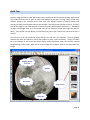
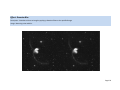
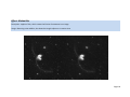
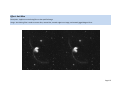
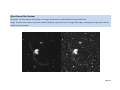
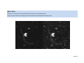
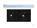
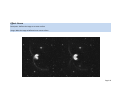
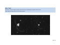
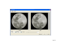
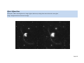
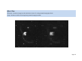
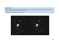
This feature lets you load multiple images onto the screen so that you
can compare “Blink” the images to see movement. The following
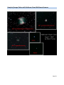
screen shows 1 of 3 frames of the planet Uranus. You have the option
of manually blinking the images or automatically blink them in a loop.
Page 47
Add Border
This feature lets you add a border around the current image. There are
several predefined borders that you can use.
Canvas Resize
Resize
Resizes the canvas the image is on.
Allows you to resize an image using several techniques.
Page 48
Histogram
Displays a histogram showing the various color channels.
Image Information
Displays detailed information on the currently displayed image.
Page 49
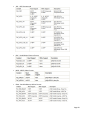
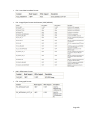
Effects Menu
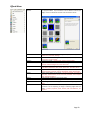
Filter and Effects
Browser
The browser shows you an example of what the image will look like after
you apply that effect. If you would like to use an effect to enhance your
image, click on the thumbnail and then click Launch Filter Screen.
Blur
Applies various blur effects to the image – Low pass (Guassian), Motion,
Radial, Zoom, Anti-Alias, Average.
Adds noise effects to the image – Removes hot pixels, median, add noise,
binary filter, and de-interlace.
Sharpens the image – Unsharp mask, sharpen, high pass filter.
Applies mathematical calculations to the image – Math functions,
Multiply, Subtract Background, Custom User Filter.
Applies distortion effects to the image – Freehand Wave, Wind, Polar,
Zoom Wave, Radial Wave, Swirl, Wave, Wave Shear, Rev Effect, Ocean.
Applies 3-D effects to the image – Emboss, Mask Convolution, Punch,
Ripple, Bending, Cylindrical, Spherize, Plane Bend, Zig Zag, Add Shadow.
Applies artistic effects to the image – Impressionist, Oilify, Glow, Diffuse
Glow, Dry, Colored Pencil, Cloud, Lens Flare, Pointillist, Color Replace,
Glass, Vignette, Fragment.
Underlay other images onto the current image.
Applies pixilation effects to the image – Pixelate, Mosaic, Picturize
Applies edge effects to the image – Detect, Smooth Edges, Edge Detect
Effect
Imposes a spatial filter on the bitmap. Spatial filters are used for
operations such as sharpening an image or detecting edges within the
image – Gradient, Laplacian, Sobel, Prewitt, Shift and Difference, Line
Segment.
Noise
Sharpen
Calculations
Distort
3-D
Artistic
Texture
Pixelate
Edge
Spatial Filters
Page 50
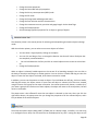
Color Menu
Auto Color Level Selection
Auto Image Level All Open
Windows
Colorize Grayscale Image
Invert
Convert to 8 bit Grayscale
Convert to 12 bit Grayscale
Convert to 16 bit Grayscale
Intensity Detect
Solarize
Posterize
Adjust Auto Level Image
Adjust Brightness /
Contrast Enhancement
Adjust Brightness
Adjust Contrast
Adjust Lighting
Adjust Hue
Adjust Tint
Adjust Saturation
Adjust Gamma
Adjust Balance Colors
Transform Halftone
Transform Increase /
Decrease color resolution
Transform Grayscale
Transform Colored Gray
This feature displays 4 images (Original, Auto Level, Auto Contrast, &
Auto Intensity. You can then change the black and white sliders until you
get the effect you like. Then select the image you want to use and click
OK.
This method makes the dark values darker and the light values lighter,
which automatically enhances shadows and brightens the image. It also
maximizes the tonal range of the image. It enhances the contrast and
intensity using the image's histogram and a color distribution-based
algorithm.
This option will go through the currently open windows and apply the
AUTO LEVEL button found on the toolbar to each window.
Changes the distribution of the red, green, or blue channels. The method
can be used as a visualization aid. More precisely, this method can be
used to show variations in a bitmap’s intensity values. This method colors
the grayscale bitmap by converting specified ranges of grayscale
intensities into corresponding RGB values.
Inverts the colors in the bitmap, making it like a photographic negative.
Converts the current image to an 8 bit grayscale image.
Converts the current image to a 12 bit grayscale image.
Converts the current image to a 16 bit grayscale image.
Applies binary segmentation to a bitmap by filtering the specified bitmap
to detect colors in a specified intensity range, in the specified color
channel. The image is divided into 2 parts, inner and outer, according to
the high/low values.
Applies an effect that mimics the accidental exposure of photographic
film to light. It does so by inverting all color data with an intensity value
greater than or equal to the threshold that you specify.
Imposes a poster effect on the bitmap by quantizing the bitmap’s colors
to a specified number of color levels per plane. For example, two levels
means two of red, two of green, and two of blue.
Performs the same function that the Auto Level toolbar button does.
Applies contrast, brightness, and intensity adjustments to enhance the
image tonal range.
Adjust the brightness of the image only.
Adjust the contrast of the image only.
Lightens or darkens all or part of a bitmap by remapping the pixel values.
This method remaps the pixel values of the bitmap across the full range
of available pixel values, in order to achieve the values you set.
Adjusts the hue of the image.
Adjusts the tint of the image.
Adjusts the saturation of the image.
Adjusts the gamma.
Redistributes the RGB values of the specified bitmap, using the values
stored in the specified structures.
Converts image to a halftoned bitmap.
Increases or decreases the resolution of an image to any bit depth.
Converts a grayscale bitmap into a colored one by mixing or replacing the
original values of the pixels with one or more new colors.
Converts a bitmap to a grayscale bitmap, then enhances the color
components based on the specified parameters. This method can be
used to give an image a “Sepia” look.
Page 51
Remap Intensity
Remap Hue
Histogram Equalize
Histogram Stretch
Intensity
Histogram Contrast
Fill
Separate RGB
Separate CMYK
Separate HSV
Separate HLS
Separate CMY
Color Merge RGB
Color Merge CMYK
Color Merge HSV
Color Merge HLS
Color Merge CMY
Count Unique Colors
Customize Palette
This method uses a lookup table to change the bitmap’s
intensity values. You can apply the change to red, green, blue,
or all color channels.
This method uses a lookup table to change a bitmap’s hue
values. This method can be used to change a range of colors to
another range of colors. For example, it could be used to
change all red pixels to any color, where a red pixel can have
any brightness and any amount of white (saturation).
Linearizes the # of pixels in the bitmap, based on the specified
color space. This can be used to bring out the detail in dark
areas of an image.
Increases the contrast in a bitmap by centering, maximizing,
and proportioning the range of intensity values.
Increases or decreases the contrast of the image in a bitmap,
using a histogram to determine the median brightness. This
method finds the median brightness of the image; then
brightens the pixels with values above the median and darkens
the pixels with values below the median.
Fills the entire image with the specified color.
Separates the bitmap by color plane to produce one grayscale
bitmap per plane. Uses the RGB color space model.
Separates the bitmap by color plane to produce one grayscale
bitmap per plane. Uses the CMYK color space model.
Separates the bitmap by color plane to produce one grayscale
bitmap per plane. Uses the HSV color space model.
Separates the bitmap by color plane to produce one grayscale
bitmap per plane. Uses the HLS color space model.
Separates the bitmap by color plane to produce one grayscale
bitmap per plane. Uses the CMY color space model.
Creates a color bitmap by merging grayscale bitmaps that were
created as color separations using the RGB color space model.
Creates a color bitmap by merging grayscale bitmaps that were
created as color separations using the CMYK color space model.
Creates a color bitmap by merging grayscale bitmaps that were
created as color separations using the HSV color space model.
Creates a color bitmap by merging grayscale bitmaps that were
created as color separations using the HLS color space model.
Creates a color bitmap by merging grayscale bitmaps that were
created as color separations using the CMY color space model.
Counts the # of unique colors in the image.
Customize the Palette.
Page 52
Preferences Menu
Program Options
Sets various options used in Deepsky Imaging.
Reset Preferences
Resets all preferences to their default values.
Dithering
Sets the dithering method to use on 8 bit images.
Paint Scaling
Sets the type of resizing to use when painting an image.
Paint Palette
Specifies whether to force use of a fixed palette when
painting images on a device that displays 256 colors or less.
Specifies whether the image history toolbar is visible. This
toolbar is used to maintain a history of all image changes,
allowing you to get back to a prior state.
When checked, the image history will be cleared when the
program starts.
Show the Image
History Toolbar
Clear Image History at
Start of Program
Page 53
Annotations Summary
Deepsky imaging includes very robust annotation support for marking up your images. Annotations can
be maintained separately from bitmaps or they can be merged onto the image. When you add an
annotation to an image and save the file, a separate annotation file named the same as the image but
with a .ANN file extension is created. Try opening the Moon with Annotations image in the
sampleimages folder.
When the image opens, you will see the moon with a bunch of annotations on it. Initially when the
image is first loaded, the annotation mode is NORMAL, which means you can’t change the annotations.
If you go into DESIGN mode, you will be able to edit the annotations. Remember, when you are in
design mode, you can add or remove annotations. Make sure you switch to normal mode to ensure you
don’t inadvertently remove annotations.
If you know that you will never change the annotations, you can use the MERGE ANNOTATION WITH
IMAGE option to permanently place the markup onto the image. Once you do this, the annotations are
gone and only the image remains.
Page 54
Annotation Properties
When you are in design mode, each annotation has many properties that you can set to change the
appearance of the annotation. Simply right click and select the properties (in the above example it’s
RULER PROPERTIES) and you will see a screen similar to the below screen.
One thing that may confuse you is when you want to change text of an annotation, do not change the
NAME tab as shown above, but rather if text is available, a TEXT tab (not shown in the above example)
will be shown.
Page 55
Annotation Features
The following information was taken from the Lead tools help file and explains many of the annotation
features available in Deepsky Imaging. LeadTools is the company that makes the imaging toolkit that
Deepsky Imaging uses. If you are a software developer, I highly recommend their toolkits.
The following annotation features are available in Deepsky Imaging:
•
New Rubber Stamp Display Style
•
New XP Style Annotation Toolbar
•
New Alpha Background Fill Option
•
New Annotation Rotate Option
•
New Annotation Side Handles
•
New Annotation Multi-select
•
New Annotation Cursors
•
New ESC to Cancel
•
New Calibrate Ruler Feature
•
New Dot Dash Lines
•
New Text Annotation Options
The following paragraphs describe each feature in more detail.
New Rubber Stamp Display Style
In previous versions of LEADTOOLS, you could draw any of 26 predefined rubber stamp annotations.
While any of these metafiles can be changed, users have asked for more contemporary-looking defaults.
LEADTOOLS has responded and developed new default images. The following figure displays a sample of
the original style and the new style:
Page 56
New XP Style Annotation Toolbar
The annotation toolbar has been updated to have a Windows-XP look and feel. The following figure
displays a sample of the original style and the new style toolbar:
New Alpha Background Fill Option:
Previous versions of LEADTOOLS supported annotations with translucent backgrounds. With version
14.5, there is an alpha option that allows you to specify an alpha value from 0 (completely transparent
background) to 255 (completely opaque background) inclusive.
When enabled, you can right-click an annotation object to display the Fill dialog with the new alpha
option. Here you can enter an alpha value from 0 – 255 inclusive. The following figure displays the Fill
dialog for the Stamp object:
Page 57
The following figure displays rectangle annotation objects using different alpha values:
New Annotation Rotate Option
In previous versions of LEADTOOLS, annotation objects could be rotated by holding the <SHIFT> key
while dragging a handle. With the new rotate options, two rotate handles are displayed on a selected
object. One of the handles is the "gripper" handle, which rotates the object when dragged. The other
handle is the "center" handle, which determines the center of rotation. The center of rotation can be
moved by dragging. The gripper handle can be moved anywhere by dragging.
Page 58
The following figure illustrates a rotate by dragging the "gripper" handle:
Page 59
The rotate handles can be reset to a default location by right-clicking the annotation object, and
selecting the Reset Rotate Handles option, as shown in the following figure:
The rotate handles can be globally hidden or displayed by right-clicking on the image (not an annotation
object), and selecting the Hide Rotate Handles For All Objects option, as shown in the following figure:
New Annotation Side Handles
In previous versions of LEADTOOLS, rectangular annotation objects were displayed with four handles to
manipulate the object. With this new feature, rectangular objects are displayed with four additional side
handles. Dragging the side handles resizes the annotation object only in one dimension. Dragging the
corner handles resizes the object in two dimensions, preserving the aspect ratio.
The following figure displays a sample of the original style and the new style:
New Annotation Multi-select
In previous versions of LEADTOOLS, you could select multiple objects and manipulate the objects by
dragging any handle of any object. When moving a handle, the results were often not intuitive. With the
new multi-select option, all selected objects are outlined with a multi-select border. The multi-select
border has eight resize handles, and two rotate handles. Now, moving, resizing, and rotating multiply
select objects is clear and easy to do.
Page 60
The following figure displays a sample of the original style and the new style:
New Annotation Cursors
This new feature displays different cursors for many tasks in automated annotation mode. This feature
displays unique annotation cursors in the following situations:
•
When hovering over a rotation gripper handle
•
When hovering over a rotation center handle
•
When hovering over any of the eight size handles—an appropriate arrow cursor is displayed
depending on the handle and the rotation of the annotation object.
•
When dragging a selection
•
When using any of the 30 annotation tools.
The following figure displays some of the new cursors:
Page 61
New ESC to Cancel
In previous versions of LEADTOOLS, the ESC key was not set to cancel actions in annotation automation
mode. With this new feature, a user can press the ESC key to cancel many actions in annotation
automation mode. For example, when drawing an annotation, pressing ESC will cancel the annotation
completely. When rotating, resizing, or moving an annotation, pressing ESC will cancel the action leaving
the annotation unchanged.
New Calibrate Ruler Feature
With this feature, a user can automatically calibrate a ruler to the desired size. This is useful when a user
wants to interactively measure something in an image. Note that there are four annotations objects
used for measuring:
•
ANN_OBJECT_RULER
•
ANN_OBJECT_POLYRULER
•
ANN_OBJECT_CROSSPRODUCT
•
ANN_OBJECT_PROTRACTOR
Any of these objects can be calibrated. To calibrate a ruler:
1. Load desired image
2. Draw an ANN_OBJECT_RULER object and size to desired size. In this
example, we will calibrate the diagonal to be 2 feet. The following
figure displays an uncalibrated ruler:
3. Right-click the ANN_OBJECT_RULER object and select Ruler
Properties, and then Ruler, as shown in the following figure:
Page 62
The following figure appears:
4. Click the Calibrate button to open the Calibrate Ruler dialog. The
following figure displays:
In the Calibrate dialog, set the Ruler Length to 2 and the Ruler
Measurement to feet. Select the Apply to Newly Created Rulers check
Page 63
box. Click the OK button to close the Calibrate dialog. Click the OK
button to save your selections and close the Ruler Properties dialog.
5. Draw a new ruler to measure any part of the image, as shown in the
following figure:
New Dot Dash Lines
Most of the LEAD annotation objects have a Line Width and Line Style option. This can be used to draw
the annotations with thick lines, and change the line style from solid to dashed or dotted. In previous
versions of LEADTOOLS, drawing annotations with thick lines (line width more than 1 pixel) required that
the line style be Solid. This is due to a limitation of Windows GDI. In version 14.5, this limitation has been
removed. Now annotation objects can be drawn with thick lines of any style. The following example
illustrates this:
New Text Annotation Options
For the following text-based annotations, you can now change the text color so that it is different from
the border color. Also, you can optionally show or hide the text.
•
ANN_OBJECT_TEXT
•
ANN_OBJECT_TEXTPOINTER
•
ANN_OBJECT_STAMP
•
ANN_OBJECT_NOTE
•
ANN_OBJECT_PUSHPIN
Page 64
For the following text based annotations, you can now optionally show or hide the border.
•
ANN_OBJECT_TEXT
•
ANN_OBJECT_STAMP
These properties can also be set for the following annotation objects for purposes of recursion:
•
ANN_OBJECT_CONTAINER
•
ANN_OBJECT_AUTOMATION
•
ANN_OBJECT_BUTTON
To see these new features:
1.
2.
3.
4.
5.
Draw an ANN_OBJECT_TEXT object
Right-click the object
Select Text Properties and then Text
In the Text dialog, select the Show Border check box
Click the Text Color button to change the color to blue. The
following figure displays the Text dialog:
6.
The following figure displays the original text object before
and after changing the text color to blue:
Page 65
Annotation Tools Available
The following tools are available on the annotation toolbar when you are in design mode.
Audio Clip Tool
The audio clip annotation object is a rectangle containing a scaled image that can be activated to play a
WAV file. In design mode, you can click and drag to specify the rectangle in the current window. A dialog
box then lets you specify the WAV file. In run mode, clicking on the icon plays the WAV file.
In design mode, you can click on the object with the right mouse button to do the following:
•
Undo the last user action.
•
Cut or copy the object to the clipboard.
•
Delete the object.
•
Select all objects.
•
Bring the object to the front or send it to the back.
•
Lock and unlock annotation objects.
•
Change the Name properties.
•
Select a WAV file to load into the object.
•
Change the fixed properties.
•
Set and manage hyperlink properties for an object or group of objects.
Button Tool
The button annotation object is an image of a standard Windows button that can be activated. In design
mode, you can click and drag to specify the size of the button in the current window. A dialog box then
lets you enter the text for the button.
In design mode, you can then click on the object with the right mouse button to do the following:
•
Undo the last user action.
•
Cut or copy the object to the clipboard.
•
Delete the object.
•
Select all objects.
•
Bring the object to the front or send it to the back.
Page 66
•
Lock and unlock annotation objects.
•
Change the Name properties.
•
Change the fill mode.
•
Change the foreground and background colors.
•
Change the font selection and font characteristics.
•
Note: Only certain font characteristics can be changed for the button tool.
•
Edit the text.
•
Change the fixed properties.
•
Set and manage hyperlink properties for an object or group of objects.
Cross Product Tool
The CrossProduct annotation object consists of two simple lines intersecting at right angles. With the
automated functions, the CrossProduct is started on a mouse-down event and completed on a mouseup event. Holding down the Shift key while drawing the CrossProduct will make the CrossProduct
annotation square.
In design mode, click on the object with the right mouse button to do the following:
•
Undo the last user action.
•
Cut or copy the object to the clipboard.
•
Delete the object.
•
Select all objects.
•
Bring the object to the front or send it to the back.
•
Lock and unlock annotation objects.
•
Change the Name properties.
•
Change the line width and style properties.
•
Change the binary raster operation (ROP2) code.
•
Change the fill mode.
•
Change the foreground and background colors.
•
Change the font selection and font characteristics.
•
Change the measurement units, precision and gauge length. Set show flags
•
Change the fixed properties.
•
Set and manage hyperlink properties for an object or group of objects.
Closed Curve Tool
The closed curve annotation object (ANN_OBJECT_CURVECLOSED) is a sequence of points that are
joined by cubic polynomials such that adjacent polynomials are continuous at the first and second
Page 67
derivates. Unlike the curve annotation object, the first and last endpoints are also joined by a curve. The
result is a smooth, continuous closed curve going through all the points.
In design mode, click on the object with the right mouse button to do the following:
•
Undo the last user action.
•
Cut or copy the object to the clipboard.
•
Delete the object.
•
Select all objects.
•
Bring the object to the front or send it to the back.
•
Lock and unlock annotation objects.
•
(If the object has multiple nodes) Add or delete nodes. Add a node by clicking on the spot
where you wish to add a node, then select Add Node. To delete a node, click on the node
you wish to delete and select Delete Node.
•
Change the Name properties.
•
Change the line width and style properties.
•
Change the binary raster operations (ROP2) code.
•
Change the fill mode and the fill pattern.
•
Change the polygonal fill mode, which controls which areas are filled when lines cross.
•
Change the foreground and background colors.
•
Change the node properties.
•
Change the fixed properties.
•
Set and manage hyperlink properties for an object or group of objects.
Curve Tool
The curve annotation object is a sequence of points that are joined by cubic polynomials such that
adjacent polynomials are continuous at the first and second derivates. The result is a smooth,
continuous curve going through all the points.
In design mode, each curve is formed with a mouse click, and the object is completed on a double click.
In design mode, click on the object with the right mouse button to do the following:
•
Undo the last user action.
•
Cut or copy the object to the clipboard.
•
Delete the object.
•
Select all objects.
•
Bring the object to the front or send it to the back.
•
Lock and unlock annotation objects.
Page 68
•
(If the object has multiple nodes) Add or delete nodes. Add a node by clicking on the spot
where you wish to add a node, then select Add Node. To delete a node, click on the node
you wish to delete and select Delete Node.
•
Change the Name properties.
•
Change the line width and style properties.
•
Change the binary raster operation (ROP2) code.
•
Change the foreground color.
•
Change the node properties.
•
Change the fixed properties.
•
Set and manage hyperlink properties for an object or group of objects.
Ellipse Tool
The Ellipse annotation object is a simple ellipse. In design mode, click and drag to specify the ellipse in
the current window. Holding down the Shift key while drawing the ellipse will make the ellipse
annotation circular.
In design mode, click on the object with the right mouse button to do the following:
•
Undo the last user action.
•
Cut or copy the object to the clipboard.
•
Delete the object.
•
Select all objects.
•
Bring the object to the front or send it to the back.
•
Lock and unlock annotation objects.
•
Change the Name properties.
•
Change the line width and style properties.
•
Change the binary raster operation (ROP2) code.
•
Change the fill mode and the fill pattern.
•
Change the foreground and background colors.
•
Change the fixed properties.
•
Set and manage hyperlink properties for an object or group of objects.
Page 69
Encrypt Tool
The encrypt annotation object is a rectangular object that is used to encrypt rectangular portions of a
bitmap. It can also be used to encrypt the entire bitmap.
In design mode, the Encrypt object is created by selecting the Encrypt tool and then clicking and
dragging the mouse to create the rectangular Encrypt object. Then while the object is selected, rightclick the object and select the Encrypt item on the Encrypt Properties menu, enter the key in the Encrypt
Properties dialog that appears, and then click Apply. In design mode, the Encrypt object is visible but
partially transparent to show the part of the bitmap that it covers.
In run mode, the encrypt object is invisible. In run mode, if an encrypt object (state encryptor) has been
applied to the bitmap, the pixels underneath the encryptor’s location are physically scrambled in a
manner that depends upon the key used when the encrypt object was created.
An encrypt annotation has two metafiles--one for when it is an encryptor, and one for when it is a
decryptor.
The encryptor metafile is changed with the Metafile option.
The decryptor metafile is changed with the Secondary Metafile option
If you have one or more encrypt objects selected and you change the "Metafile" then the encryptor
metafile changes for all of the selected encrypt objects.
You can also change the metafile and secondary metafiles for all newly created encrypt objects by rightclicking on the image (but not on an annotation), selecting Default Properties and changing the
primary/secondary metafiles.
Overlapping regions can be encrypted. When encrypting overlapping regions, note the following points:
•
All annotation objects have an order in which they are drawn (the Z-order).
•
The encryptors are encrypted from the front of the Z-order to the back.
•
Those that are drawn first are encrypted first. Those that are drawn last ("on top" of other
encryptors) are encrypted last.
•
The Z-order can be changed through automation by right-clicking and choosing "Send To
Front" or "Send To Back".
•
The decryptors are decrypted in reverse order of the encryptors.
Once applied, the portion of the bitmap under the encrypt object becomes scrambled, and the encrypt
object changes state to become a decryptor. Using different keys before calling this function gives
different scrambling patterns the decryptor state differs from the encryptor state in that a decryptor
cannot be moved, and cannot be changed to an encryptor. The scrambling can be removed by calling
AnnEncryptApply on the decryptor with the appropriate arguments. If successful, the decryptor state
Page 70
changes to encryptor. An encrypt object in that encrytpor state can be moved, can have its key changed,
and can be changed to a decryptor.
The encrypt object is useful for encrypting portions of a bitmap. After encrypting, the scrambled bitmap
cannot easily be unscrambled without the associated annotation file. The scrambling can be removed by
using the associated annotation file, or by using automation mode to manually change the encryptor to
a decryptor, position it correctly, and setting the key appropriately.
When a bitmap that has had portion(s) of the bitmap encrypted is saved, the encryption information is
saved with the rest of the annotation information in the associated annotation information file.
Polyruler Tool
The polyruler annotation object is an array of points that create a sequence of joined rulers. In design
mode, each line segment is formed with a mouse click, and the object is completed on a double click.
The polyruler can be used to measure the distance of an irregularly shaped object. As ruler segments are
added, removed, or changed in length, a running total of the total distance is displayed.
Holding down the Shift key while drawing the rulers will draw the rulers at an angle that is a multiple of
45 degrees.
In design mode, click on the object with the right mouse button to do the following:
•
Undo the last user action.
•
Cut or copy the object to the clipboard.
•
Delete the object.
•
Select all objects.
•
Bring the object to the front or send it to the back.
•
Lock and unlock annotation objects.
•
(If the object has multiple nodes) Add or delete nodes. Add a node by clicking on the spot
where you wish to add a node, then select Add Node. To delete a node, click on the node
you wish to delete and select Delete Node.
•
Change the Name properties.
•
Change the line width and style properties.
•
Change the binary raster operation (ROP2) code.
•
Change the fill mode.
•
Change the foreground and background colors.
•
Change the font selection and font characteristics.
•
Change the measurement units, precision and gauge length.
•
Change the node properties.
•
Change the fixed state.
Page 71
•
Set and manage hyperlink properties for an object or group of objects.
Rich Text Tool
The Rich Text annotation object is a rectangle containing text that supports Rich Text Format (RTF).
In design mode, click and drag to specify the rectangle in the current window. Holding down the Shift
key while drawing the rectangle will make the text annotation square. A dialog box then lets the user
enter the text. A menu also appears to allow further formatting of text. Formatting support includes:
•
•
•
•
•
•
•
•
•
•
•
Font
Font size
Bold
Italic
Underline
Foreground Color
Background Color
Bullets
Numbering
Indenting
Alignment
As soon as the Text object is created, the text will be highlighted. The text may be edited immediately.
While in design mode double click on a text object to edit the text.
In design mode, click on the object with the right mouse button to do the following:
•
Undo the last user action.
•
Cut or copy the object to the clipboard.
•
Delete the object.
•
Select all objects.
•
Bring the object to the front or send it to the back.
•
Lock and unlock annotation objects.
•
Change the Name properties.
•
Change the foreground color.
•
Change the fixed properties.
•
Set and manage hyperlink properties for an object or group of objects.
Freehand Hot Spot Tool
The freehand hot spot annotation object is an array of points that create a sequence of joined lines.
With the automated functions, in design mode, each line segment is formed with a mouse move when
Page 72
the left button is down, and the object is completed on a mouse up. In run mode, the object is
transparent, but the mouse pointer changes to a hand when it is over the object.
In design mode, click on the object with the right mouse button to do the following:
•
Undo the last user action.
•
Cut or copy the object to the clipboard.
•
Delete the object.
•
Select all objects.
•
Bring the object to the front or send it to the back.
•
Lock and unlock annotation objects.
•
(If the object has multiple nodes) Add or delete nodes. Add a node by clicking on the spot
where you wish to add a node, then select Add Node. To delete a node, click on the node
you wish to delete and select Delete Node.
•
Change the name.
•
Change the line width and style properties.
•
Change the binary raster operation (ROP2) code.
•
Change the node properties.
•
Select a metafile to load into the Freehand Hotspot.
•
Change the fixed properties.
•
Set and manage hyperlink properties for an object or group of objects.
Freehand Line Tool
The freehand line annotation object is an array of points that create a sequence of joined lines. In design
mode, each line segment is formed with a mouse move event when the left button is down, and the
object is completed on a mouse up event.
In design mode, click on the object with the right mouse button to do the following:
•
Undo the last user action.
•
Cut or copy the object to the clipboard.
•
Delete the object.
•
Select all objects.
•
Bring the object to the front or send it to the back.
•
Lock and unlock annotation objects.
•
(If the object has multiple nodes) Add or delete nodes. Add a node by clicking on the spot
where you wish to add a node, then select Add Node. To delete a node, click on the node
you wish to delete and select Delete Node.
•
Change the Name properties.
•
Change the line width and style properties.
Page 73
•
Change the binary raster operations (ROP2) code.
•
Change the foreground color.
•
Change the node properties.
•
Change the fixed properties.
•
Set and manage hyperlink properties for an object or group of objects.
Highlight Tool
The highlight annotation object is a rectangle with default properties that are appropriate for
highlighting an area. In design mode, you can click and drag to specify the rectangle in the current
window.
You can then click on the object with the right mouse button to do the following:
•
Undo the last user action.
•
Cut or copy the object to the clipboard.
•
Delete the object.
•
Select all objects.
•
Bring the object to the front or send it to the back.
•
Lock and unlock annotation objects. See Password Dialog Box for Annotations.
•
Change the Name properties. See Name Dialog Box for Annotations.
•
Change the background color. See Color Dialog Box for Annotations.
•
Change the fixed properties. See Fixed Dialog Box for Annotations.
•
Set and manage hyperlink properties for an object or group of objects.
Hotspot Tool
The HotSpot annotation object is a rectangle that can be activated for an application-defined purpose. In
design mode, the rectangle contains a scaled image. Click and drag to specify the rectangle. Holding
down the Shift key while drawing the hot spot will make the HotSpot annotation square. In run mode,
the object is transparent, but the mouse pointer changes to a hand when it is over the object. In run
mode, clicking on the button triggers an event LtAnnEvent. You can add code to process the event. (The
example program merely pops up a message box.)
In design mode, click on the object with the right mouse button to do the following:
•
Undo the last user action.
•
Cut or copy the object to the clipboard.
•
Delete the object.
•
Select all objects.
•
Bring the object to the front or send it to the back.
Page 74
•
Lock and unlock annotation objects.
•
Change the Name properties.
•
Select a metafile to load into the stamp.
•
Change the fixed properties.
•
Set and manage hyperlink properties for an object or group of objects.
Line Tool
The Line annotation object is a simple line. In design mode, the line is started on a mouse-down event
and completed on a mouse-up event. Holding down the Shift key while drawing the line will draw the
line at an angle that is a multiple of 45 degrees.
In design mode, click on the object with the right mouse button to do the following:
•
Undo the last user action.
•
Cut or copy the object to the clipboard.
•
Delete the object.
•
Select all objects.
•
Bring the object to the front or send it to the back.
•
Lock and unlock annotation objects.
•
Change the default Name properties.
•
Change the line width and style properties.
•
Change the binary raster operation (ROP2) code.
•
Change the foreground color.
•
Change the fixed properties.
•
Set and manage hyperlink properties for an object or group of objects.
Note Tool
The Note annotation object is a rectangle with a shadow border and color background (yellow by
default). It contains a character string with font properties. The text will wrap on word breaks within the
object's specified rectangle. In design mode, click and drag to specify the rectangle in the current
window. Holding down the Shift key while drawing the note will make the Note annotation square. A
dialog box then lets the user enter the text.
As soon as the Note object is created, the text will be highlighted. The text may be edited immediately.
While in design mode double click on a text object to edit the text.
As soon as the Note object is created, the text will be highlighted. The text may be edited immediately.
While in design mode double click on a note object to edit the text.
In design mode, click on the object with the right mouse button to do the following:
Page 75
•
Undo the last user action.
•
Cut or copy the object to the clipboard.
•
Delete the object.
•
Select all objects.
•
Bring the object to the front or send it to the back.
•
Lock and unlock annotation objects.
•
Change the Name properties.
•
Change the foreground and background colors.
•
Change the font selection and font characteristics.
•
Edit the text.
•
Change the fixed properties.
•
Set and manage hyperlink properties for an object or group of objects.
Point Tool
The hot spot annotation object (ANN_OBJECT_POINT) is single point. With the automated functions, in
design mode, each point is formed with a mouse click.
In design mode, you can click on the object with the right mouse button to do the following:
•
Undo the last user action.
•
Cut or copy the object to the clipboard.
•
Paste the object.
•
Delete the object.
•
Select all objects.
•
Bring the object to the front or send it to the back.
•
Lock and unlock annotation objects.
•
Change the name properties.
•
Change the line properties.
•
Change the ROP2 properties.
•
Make the point transparent or not transparent.
•
Change the transparent color.
•
Select a bitmap file.
•
Change the point properties.
•
Change the fixed properties.
•
Set and manage hyperlink properties for an object or group of objects.
•
Flip the object.
Page 76
Pointer Tool
The Pointer annotation object is defined by two points, with the an arrow at the first point. In design
mode, click and drag to specify the points in the current window. Holding down the Shift key while
drawing the pointer will draw the pointer annotation object at an angle that is a multiple of 45 degrees.
In design mode, click on the object with the right mouse button to do the following:
•
Undo the last user action.
•
Cut or copy the object to the clipboard.
•
Delete the object.
•
Select all objects.
•
Bring the object to the front or send it to the back.
•
Lock and unlock annotation objects.
•
Change the Name properties.
•
Change the line width and style properties.
•
Change the binary raster operations (ROP2) code.
•
Change the foreground color.
•
Change the fixed properties.
•
Set and manage hyperlink properties for an object or group of objects.
Polygon Tool
The Polygon annotation object is an array of points that define the vertices of a polygon. In design
mode, each line segment is formed with a mouse click, and the object is completed on a double click,
which closes the polygon with a line from the last point to the first point.
In design mode, click on the object with the right mouse button to do the following:
•
Undo the last user action.
•
Cut or copy the object to the clipboard.
•
Delete the object.
•
Select all objects.
•
Bring the object to the front or send it to the back.
•
Lock and unlock annotation objects.
•
Add or delete nodes. Add a node by clicking on the spot where you wish to add a node, then
select Add Node. To delete a node, click on the node you wish to delete and select Delete
Node.
•
Change the Name properties.
Page 77
•
Change the line width and style properties.
•
Change the binary raster operation (ROP2) code.
•
Change the fill mode and the fill pattern.
•
Change the polygonal fill mode, which controls which areas are filled when lines cross.
•
Change the foreground and background colors.
•
Change the node properties.
•
Change the fixed properties.
•
Set and manage hyperlink properties for an object or group of objects.
Polyline Tool
The Polyline annotation object is an array of points that create a sequence of joined lines. In design
mode, each line segment is formed with a mouse click, and the object is completed on a double click.
In design mode, click on the object with the right mouse button to do the following:
•
Undo the last user action.
•
Cut or copy the object to the clipboard.
•
Delete the object.
•
Select all objects.
•
Bring the object to the front or send it to the back.
•
Lock and unlock annotation objects.
•
(If the object has multiple nodes) Add or delete nodes. Add a node by clicking on the spot
where you wish to add a node, then select Add Node. To delete a node, click on the node
you wish to delete and select Delete Node.
•
Change the Name properties.
•
Change the line width and style properties.
•
Change the binary raster operation (ROP2) code.
•
Change the foreground color.
•
Change the node properties.
•
Change the fixed properties.
•
(If the object has multiple nodes) Add or delete nodes. Add a node by clicking on the spot
where you wish to add a node, then select Add Node. To delete a node, click on the node
you wish to delete and select Delete Node.
•
Set and manage hyperlink properties for an object or group of objects.
Protractor Tool
The Protractor annotation object (ANN_OBJECT_PROTRACTOR) consists of two simple lines joined at a
vertex to create an angle. With the automated functions, the first line of the protractor is started on a
Page 78
mouse-down event and completed on a second mouse-down event. The second line is completed on a
third mouse-down event. Holding down the Shift key while drawing either of the two lines will draw the
line at an angle that is a multiple of 45 degrees.
In design mode, click on the object with the right mouse button to do the following:
•
Undo the last user action.
•
Cut or copy the object to the clipboard.
•
Delete the object.
•
Select all objects.
•
Bring the object to the front or send it to the back.
•
Lock and unlock annotation objects.
•
Change the Name properties.
•
Change the line width and style properties.
•
Change the binary raster operation (ROP2) code.
•
Change the fill mode.
•
Change the foreground and background colors.
•
Change the measurement units, precision and gauge length. Set show flags
•
Set the protractor options.
•
Change the fixed properties.
•
Set and manage hyperlink properties for an object or group of objects.
Push Pin Tool
The PushPin annotation object (ANN_OBJECT_PUSHPIN) is a rectangle containing a scaled image that
can be activated to show a hidden note. With the automated functions, in design mode, the user clicks
and drags to specify the rectangle in the current window. Holding down the Shift key while drawing the
PushPin will make the PushPin annotation square. A dialog box then lets the user specify the preferred
options. In run mode, clicking on the icon display the hidden note.
A PushPin object has a primary bitmap, (manipulated using the AnnSetBitmap method and the
AnnGetBitmap method) when the text is shown, and a secondary bitmap, changed using the
AnnPredefinedRaster property. The primary bitmap is shown with the note text. The secondary bitmap
is shown by itself when the note is minimized.
In design mode, the PushPin object shows the text and displays the primary bitmap. In run mode, the
object shows/hides the text when clicked.
As soon as the PushPin object is created, the text will be highlighted. The text may be edited
immediately. While in design mode double click on a PushPin object to edit the text. To get out of edit
mode:
Page 79
•
•
•
Press escape. This cancels the changes.
Press Ctrl-Enter. This accepts the changes.
Click outside the edit box. This accepts the changes.
In design mode, click on the object with the right mouse button to do the following:
•
Undo the last user action.
•
Cut or copy the object to the clipboard.
•
Delete the object.
•
Select all objects.
•
Bring the object to the front or send it to the back.
•
Lock and unlock annotation objects.
•
Change the Name properties.
•
Change the foreground and background colors.
•
Change the font selection and font characteristics.
•
Edit the text.
•
Set the primary and secondary bitmaps.
•
Change the fixed properties.
•
Set and manage hyperlink properties for an object or group of objects.
Rectangle Tool
The Rectangle annotation object is a simple rectangle. In design mode, click and drag to specify the
rectangle in the current window. Holding down the Shift key while drawing the rectangle will make the
rectangle annotation square.
In design mode, click on the object with the right mouse button to do the following:
•
Undo the last user action.
•
Cut or copy the object to the clipboard.
•
Delete the object.
•
Select all objects.
•
Bring the object to the front or send it to the back.
•
Lock and unlock annotation objects.
•
Change the Name properties.
•
Change the line width and style properties.
•
Change the binary raster operation (ROP2) code.
•
Change the fill mode and the fill pattern.
•
Change the foreground and background colors.
Page 80
•
Change the fixed properties.
•
Set and manage hyperlink properties for an object or group of objects.
Redaction Tool
The Redaction annotation object is a rectangle with default properties that are appropriate for blacking
out an area. In design mode, click and drag to specify the rectangle in the current window. Holding down
the Shift key while drawing the rectangle will make the Redaction annotation square.
In design mode, click on the object with the right mouse button to do the following:
•
Undo the last user action.
•
Cut or copy the object to the clipboard.
•
Delete the object.
•
Select all objects.
•
Bring the object to the front or send it to the back.
•
Lock and unlock annotation objects.
•
Change the Name properties.
•
Change the background color.
•
Set and manage hyperlink properties for an object or group of objects
Rubber Stamp Tool
The rubber stamp annotation object is a stamp object that has a metafile. For more information about
the stamp tool, refer to Stamp Tool.
Ruler Tool
The ruler annotation object is a line that can be used to measure the distance between two points of the
original image.
In design mode, you can click on the object with the right mouse button to do the following:
•
Undo the last user action.
•
Cut or copy the object to the clipboard.
•
Delete the object.
•
Select all objects.
•
Bring the object to the front or send it to the back.
•
Lock and unlock annotation objects.
Page 81
•
Change the Name properties.
•
Change the line width and style properties.
•
Change the binary raster operation (ROP2) code.
•
Change the fill mode.
•
Change the foreground and background colors.
•
Change the font selection and font characteristics.
•
Change the measurement units, precision and gauge length. Set the show flags.
•
Change the fixed properties.
•
Set and manage hyperlink properties for an object or group of objects.
Selection Pointer Tool
The selection pointer is the mouse pointer for selecting and manipulating annotation objects in design
mode.
With the selection pointer, you can select one or more objects as follows:
•
You can select a single object by clicking on the object.
•
You can click and drag to form a rectangular selection area that will select all objects that
are completely contained within it.
•
You can hold down the shift key and click on several objects one-at-a-time to select them
all.
•
Change the fixed properties.
When an object is selected, handles appear on the corners of its bounding rectangle. You can click on
the body of the object and drag it to another position. You can click on a handle and drag to resize the
object. If more than one object is selected, all of them are moved or resized.
In addition, you can use this pointer to rotate an object. If you hold down the shift key, click on a handle,
and drag the mouse, the object rotates. If more than one object is selected, all of them are rotated,
using the center of the group as the center of rotation. You cannot rotate a note, button, or audio clip. If
you rotate a group that includes one of these objects, the object will move to the new position, but will
retain its orientation.
The popup menu is also affected if more than one object is selected. In that case, when you click the
right mouse button, the popup menu lets you change the properties of all the selected objects, and it
lets you delete all the selected objects.
Stamp Tool
The Stamp annotation object (ANN_OBJECT_STAMP) can be a bitmap image, a metafile, or a text string
in a rectangular frame. Only one of these three can be displayed at any time—setting the object to one
Page 82
of these destroys any settings for the other two. Initially, the ANN_OBJECT_STAMP displays text. In
design mode, click and drag to specify a rectangle. Holding down the Shift key while drawing the
rectangle will make the Stamp annotation square. Then, if a text string is specified, the text is centered
in the rectangle. If a bitmap or metafile is specified, the bitmap or metafile is scaled to fit the rectangle.
In design mode, click on the object with the right mouse button to do the following:
•
Undo the last user action.
•
Cut or copy the object to the clipboard.
•
Delete the object.
•
Select all objects.
•
Bring the object to the front or send it to the back.
•
Lock and unlock annotation objects.
•
Change the Name properties.
•
Change the line width and style properties.
•
Change the binary raster operations (ROP2) code.
•
Change the fill mode and the fill pattern.
•
Change the foreground and background colors.
•
Change the font selection and font characteristics.
•
Edit the text.
•
Select an image file to load into the stamp.
•
Select a metafile to load into the stamp.
•
Change the fixed properties.
•
Set and manage hyperlink properties for an object or group of objects.
Text Tool
The Text annotation object is a rectangle containing a character string with font properties. The text will
wrap on word breaks within the object's specified rectangle. In design mode, click and drag to specify
the rectangle in the current window. Holding down the Shift key while drawing the rectangle will make
the text annotation square. A dialog box then lets the user enter the text.
As soon as the Text object is created, the text will be highlighted. The text may be edited immediately.
While in design mode double click on a text object to edit the text.
As soon as the Text object is created, the text will be highlighted. The text may be edited immediately.
While in design mode double click on a text object to edit the text.
In design mode, click on the object with the right mouse button to do the following:
•
Undo the last user action.
•
Cut or copy the object to the clipboard.
Page 83
•
Delete the object.
•
Select all objects.
•
Bring the object to the front or send it to the back.
•
Lock and unlock annotation objects.
•
Change the Name properties.
•
Change the fill mode.
•
Change the foreground and background colors.
•
Change the font selection and font characteristics.
•
Edit the text.
•
Change the fixed properties.
•
Set and manage hyperlink properties for an object or group of objects.
Text Pointer Tool
The text pointer annotation object (ANN_OBJECT_TEXTPOINTER) is a rectangle with a line that starts
from one of the four corners. The other endpoint of the line can be moved to point to anything on the
underlying image. The rectangle contains a character string with font properties. The text will wrap on
word breaks within the object's specified rectangle.
In design mode, click and drag to specify the rectangle in the current window. After letting up on the
mouse button, the rectangle is specified. Moving the mouse now specifies the line, with a final mouse
click defining the line.
Holding down the Shift key while drawing the rectangle will make the text annotation square. Holding
down the Shift Key will snap the line to angles of 45 degrees.
After the text pointer is defined, a dialog box then lets the user enter the text. As soon as the Text object
is created, the text will be highlighted. The text may be edited immediately. While in design mode
double-click on a text object to edit the text.
When moving a text pointer, the pointer endpoint of the line can remain fixed, or move with the rest of
the text pointer. To change this setting in automation mode, select or deselect the Fixed Pointer check
box on the Text Dialog Box for Annotations.
In design mode, click on the object with the right mouse button to do the following:
•
Undo the last user action.
•
Cut or copy the object to the clipboard.
•
Delete the object.
•
Select all objects.
•
Move the object to the front of the Z-order.
•
Move the object to the back of the Z-order.
Page 84
•
Lock and unlock annotation objects.
•
Change the Name properties.
•
Change the line properties.
•
Change the binary raster operations (ROP2) code.
•
Change the fill mode.
•
Change the foreground and background colors.
•
Change the font selection and font characteristics.
•
Edit the text.
•
Change the fixed state.
•
Set and manage hyperlink properties for an object or group of objects.
Page 85
Compression Quality Factors
You can specify a quality factor when saving an image file to LEAD, JFIF, LEAD2JFIF, LEAD2JFIF, JTIF,
LEAD1JTIF, and LEAD2JTIF. The quality factor (Q factor) is a number that determines the degree of loss in
the compression process. You can set a value from 2 to 255, where 2 is the highest quality and 255 is the
most compression.
For JFIF and JTIF compression only, you can also use a factor of 0 to produce lossless JPEG files
For LEAD CMP compression (8-bit, 12-bit and 24-bit only), you can also use one of the following
enhanced options:
Q Factor
PQ1
Predefined options for LEAD only
(-1) Perfect quality 1
PQ2
This option compresses all colors of a 24-bit file and maintains
the quality of the original image at a smaller file size. As the
name suggests, there is no visual loss of color at this setting.
(-2) Perfect quality 2
QFS
This will produce a smaller file size than PQ1 while
maintaining similar quality.
(-3) Quality far more important than size
QMS
This option removes colors not noticed by the human eye.
Most viewers cannot tell the difference between an image
compressed at this level and the original image.
(-4) Quality more important than size
QS
While more colors are removed, most of them are colors or
shades that are close to one another. The compressed image
will appear very much like the original image. It will take some
study to see the difference.
(-5) Quality and size equally important
SQS
This option provides the highest compression while
maintaining good image quality. Try this option first, then
move up or down the list accordingly to obtain acceptable
compression size and image quality.
(-6) Size more important that quality (sharp)
This option is recommended for images that have sharp
edges. For example, an image that has a text overlay or an
image with many straight lines. While it creates a larger file
than the next option, it retains better edges.
Page 86
SQT
(-7) Size more important than quality (less tiling)
MCQ
This option produces less tiling in the image than the previous
options. However, it may distort text or straight lines. It is a
good option for image database applications.
(-8) Maximum compression keeping quality
MC
This option provides maximum compression
maintaining as high as possible image quality.
(-9) Maximum compression
while
This option gives maximum compression. It is equivalent to a
Q factor of 255.
For the PNG format, the qFactor can be a value between 0 and 9. 0 = (default compression), 1 (fastest
For the ABC compression (FILE_ABC and FILE_TIF_ABC), the qFactor can be one of the following values:
Q Factor
QFACTOR_ABCQ_LOSSLESS
QFACTOR_ABCQ_VIRTUALLOSSLESS
QFACTOR_ABCQ_REMOVEBORDER
QFACTOR_ABCQ_ENHANCE
QFACTOR_ABCQ_MODIFIED1
QFACTOR_ABCQ_MODIFIED1_FAST
QFACTOR_ABCQ_MODIFIED2
QFACTOR_ABCQ_MODIFIED2_FAST
QFACTOR_ABCQ_MODIFIED3
Predefined options for LEAD only
[0] Lossless compression. This option compresses
a 1-bit file and maintains image data unchanged.
Highest quality.
[1] Lossy compression. This option removes the
image's noisy pixels and compresses it to a
smaller file size than ABCQ_LOSSLESS.
[2] Lossy compression. This option removes the
image's border, if it exists, and compresses it to a
smaller file size than ABCQ_ VIRTUALLOSSLESS.
[3] Lossy compression. This option cleans up the
image, removes its border if it exists, and
compresses it to a smaller file size than
ABCQ_REMOVEBORDER.
[4] Lossy compression. This option cleans up the
image, removes its border if it exists, and
compresses it to a smaller file size than
ABCQ_ENHANCE. However, it may distort text or
straight lines.
[5] Same as ABCQ_MODIFIED1 without the
border remove or image clean processes.
[6] Lossy compression. This option cleans up the
image, removes its border if it exists, and
compresses it to a smaller file size than
ABCQ_MODIFIED1. However, it may distort text
or straight lines. Maximum compression.
[7] Same as ABCQ_MODIFIED2 without the
border remove or image clean processes.
[8] Lossy compression. Provides faster encode
and decode speed than ABCQ_MODIFIED1 or
Page 87
QFACTOR_ABCQ_MODIFIED3_FAST
QFACTOR_ABCQ_LOSSLESS_FAST
QFACTOR_ABCQ_LOSSY_FAST
ABCQ_MODIFIED2. Provides the maximum
compression.
[9] Same as ABCQ_MODIFIED3 without the
border remove or image clean processes.
[10]
Faster
lossless
compression
than
ABCQ_LOSSLESS. This option compresses a 1-bit
file and maintains image data unchanged.
Highest quality. Does not produce compression
ratios as high as ABCQ_LOSSLESS.
[11] Lossy compression. This is the fastest ABC
lossy compression option. Does not produce
compression ratios as high as the other lossy
options.
Compression Using LEAD and JPEG Formats
Compression of color and grayscale graphic image files is useful because the files are big. They can range
from 100 kilobytes to more than 200 megabytes. Compressing the image files does the following:
•
Dramatically decreases the storage requirements
•
Improves the input and output speed within a system
•
Improves the transmission speed over networks or phone lines
By incorporating the LEAD and JPEG image compression, you can develop applications that would be
impractical otherwise. Image files can be reduced to 200 times smaller than their original size.
The LEAD CMP compression format was created by LEAD Technologies, Inc., and it delivers a much
smaller file size and better image quality than other compression techniques, including JPEG.
LEAD's CMP file format allows for decompression to a 24-bit medium at 24-bit color and to an 8-bit
medium at 8-bit color without sacrificing image quality. This eliminates the need to convert all images to
8 bits in order to support the low end users or to save one 8-bit file and one 24-bit file. The result is one
much smaller file size that can be viewed on a 24-bit video card at 24-bit true color, as well as on an 8bit VGA card at 256 colors.
LEAD's CMW format uses Wavelet CMP compression. Currently, 24 color images and 8, 12 and 16-bit
grayscale images are supported in this format.
The amount of compression is controllable, allowing the compressed image quality to match the needs
of your application. Compression Quality Factors describes how the quality factors are used.
JPEG Compliant
JPEG and LEAD CMP compression are intended for use with high resolution images, and they are
impractical for use with 4- or 1-bit images.
Page 88
You can use the CCITT, LEAD 1-bit, RLE, LZW, and ZIPLib compression methods available in many of
LEADTOOLS supported formats.
8 and 24-bit Images
Using JPEG and LEAD CMP or CMW compression, color images are 24 bits per pixel, and grayscale
images are 8 bits per pixel. Therefore, to compress an 8-bit color image, the internal JPEG and LEAD CMP
or CMW compression functions must convert the 8-bit data into raw RGB 24-bit before compressing it as
a color image.
Compressing the original 24-bit image will result in a smaller file size and higher quality than
compressing an optimized 8-bit color image.
LEADTOOLS functions compress 8-bit grayscale as 8-bit grayscale JPEG or CMP images.
You can use RLE, LZW and ZIPLib (PNG) compression methods available in many of the supported
formats.
Summary of All Supported Image File Formats
•
ABIC - ABIC Format
•
AFP - AFP Format
•
ANI - Windows Animated Cursor
•
AVI - Windows AVI Format -
Deepsky Imaging can open an AVI file to get the first frame of the image. Owners of Stellacam
II and III CCD video cameras who capture AVI will appreciate this feature.
Page 89
•
BMP - Windows Bitmap Formats
•
CIN - Cineon Format
•
CLP - Microsoft Windows Clipboard Format
•
CMP - LEAD Compressed
•
CMW - LEAD Wavelet Compressed
•
CRW - Canon RAW Format
•
CUR - Windows Cursors and Icons
•
CUT - Dr. Halo Format
Page 90
•
DCR - Kodak Professional Digital Camera Format
•
DCS - Kodak Professional Digital Camera System Format
•
DCX - DCX Format
•
DJVU - DjVu Format
•
ECW - Enhanced Compressed Wavelet Format
•
EMF - Windows Metafile Formats
•
EPS - Encapsulated PostScript Format
Page 91
•
EXIF - Exif Formats
•
FIT - FITS Format
•
FLC - Flic Animation Format
•
FPX - Kodak Format
•
GIF - Compuserve GIF Format
Page 92
•
ICO - Windows Icons
•
IFF - Interchange File Formats
•
JBG - JBIG Format
Page 93
•
JPG - JPEG Compressed
•
KDC - Kodak Digital Camera Format
•
MPG - MPEG Video Format
•
PBM - Portable Bitmap Utilities Format
Page 94
•
PCD - Kodak Format
•
PCT - Macintosh Pict Format
•
PCX - PCX Format
•
PNG - Portable Network Graphics Format
•
PSD - PhotoShop 3.0 Format
•
PSP - Paint Shop Pro Format
•
PTK - PTOCA Format
Page 95
•
RAS - SUN Raster Format
•
SCT - Scitex Continuous Tone Format
•
SFF - Structured Fax File Format
•
SGI - Silicon Graphics Image Format
•
SID - MrSid Format
•
TGA - Truevision TARGA Format
Page 96
•
TIFF - Tagged Image File Format
•
TIFF - Tagged Image File Format / CCITT & TIFX - Xerox Internet Fax File Format
Page 97
•
WBMP - Wireless Bitmap Format
•
WMF - Windows Metafile Formats
•
WPG - WordPerfect Format
Page 98
•
XPM – XpicMap
•
XWD - X WindowDump
•
ABC - ABC Format
•
AWD - Microsoft FAX Format
•
CAL - CALS Raster Format
•
CMP - LEAD 1-Bit Format
•
FAX - Raw Fax Format
Page 99
•
FAX - LaserView LaserData Format
•
ICA - Image Object Content Architecture (IOCA/MODCA)
•
IMG - GEM Image Format
•
ITG - Intergraph Format
Page 100
•
MAC - MacPaint Format
•
MSP - Microsoft Paint
•
SMP - Xionics Format
•
WFX - WinFax Format
•
XBM - XBitMap Format
Page 101
Deepsky Imaging Effects Gallery
Blur Effects
The following pages show off some of the effects that Deepsky Imaging can do to your images. While many aren’t practical for astronomy, they
nonetheless look pretty cool.
Page 102
Effect: Gaussian Blur
Description: Smoothes or blurs an image by applying a Gaussian filters to the specified image.
Usage: Removing noise and blur.
Page 103
Effect: Motion Blur
Description: Applies a filter, which creates the illusion of movement in an image.
Usage: Removing noise and Blur, also shows the image’s objects as in motion view.
Page 104
Effect: Zoom Blur
Description: Blurs the image along radial lines starting from a specified center point.
Usage: Simulates the blur of capturing the image while zooming the camera
Page 105
Effect: Radial Blur
Description: Blurs the image by rotating the pixels around the specified center point
Usage: Simulates the blur of capturing the image while rotating the camera
Page 106
Effect: Anti Alias
Description: Applies an anti-aliasing filter to the specified image
Usage: Anti-aliasing filter is used to remove alias, remove blur, smooth edges in an image, and smooth jagged diagonal lines.
Page 107
Before
After
Page 108
Effect: Average
Description: Changes the color of each pixel in a image to the average color of pixels in its neighborhood. This results in a blur effect.
Usage: Removing noise and blur.
Page 109
Noise Filters
Page 110
Effect: Remove Hot Pixels
Description: Removes single pixels from the image caused by cosmic ray hits or by defects of the CCD
Usage: Use this feature to find and remove “hot pixels”, which are bright isolated points on the image.
Before
After
Page 111
Effect: Median
Description: Changes the color of each pixel in an image to the median color of pixels in its neighborhood.
Usage: The Median filter can be used to remove negative exponential, blur, and salt and pepper type of noise while preserving the edge details within
an image.
Page 112
Effect: Add Noise
Description: Adds random pixels to an image, letting you specify the percentage of coverage and the color plane.
Usage: Adding random noise to the image
Page 113
Effect: Binary Filter (Erosion)
Description: This filter imposes a binary filter on an image. It performs a user defined effect by using suitable mask.
Usage: This filter can be used for the erosion or dilation of objects, removal of noise in an image, detect edges, smoothing the image, and can also be
used for area measurement
Page 114
Effect: Binary Filter (Dilation)
Description: This filter imposes a binary filter on an image. It performs a user defined effect by using suitable mask.
Usage: This filter can be used for the erosion or dilation of objects, removal of noise in an image, detect edges, smoothing the image, and can also be
used for area measurement
Page 115
Effect: Deinterlace
Description: Deinterlaces a video source image
Usage: Remove interlacing lines from an image taken from a video source
Page 116
Sharpening Filters
Page 117
Effect: Unsharp Mask
Description: Sharpens the specified image by applying the unsharp mask. Unsharpen mask tends to show more details in areas of an image that are
normally not visible.
Usage: Unsharp mask is a technique used to enhance the edges of an image, remove blur, and increase image's sharpness.
Page 118
Effect: Sharpen
Description: Increases or decreases the sharpness of the image in the specified image.
Usage: Sharpen the image edges
Page 119
Effect: High Pass Filter
Description: Removes low frequency details in an image, resulting in a sharpened image.
Usage: Sharpened the image.
Page 120
Calculation Filters
Page 121
Effect: Multiply
Description: Increases or decreases the brightness in the image by multiplying its colors with constant.
Usage: Changing image brightness.
Page 122
Effect: Subtract Background
Description: Removes the background from an image
Usage: Improving the quality of the image, remove background and increase the visibility of the details
Page 123
Page 124
Effect: User Filter
Description: Apply filtering on the image based on specified user defined mask coefficients.
Usage: Apply user defied filter on the image
Page 125
Add or Stitch Bitmaps Together
Page 126
Effect: Add Bitmaps
Description: Adds or averages the images in a list
Usage: This filter can be used to remove noise, combine images, and improve night vision images. Noise can be reduced by averaging a list of images
together. Adding a list of images together can be used to show details in low intensity areas of an image.
Image 1 Before
Image 2 Before
Image Combined using Average
Page 127
Effect: Stitch Bitmaps Together Into 1 image
Description: Stitch multiple images making them into a single image.
Usage: Use this dialog to produce a new bitmap that is composed of 1 or more source bitmaps
Resulting image stitched together
Page 128
Distortion Effects
Page 129
Effect: Free Hand Wave
Description: Distorts the image by a free hand drawn wave in any specified direction
Usage: Makes the image look like as if it is reflected on user defined waves.
Page 130
Effect: Wind
Description: Creates thin lines, directed along certain angle, on the specified image
Usage: Apply this effect on the image objects to show that it has been exposed by a direct wind.
Page 131
Effect: Polar
Description: Converts the image from rectangular to polar coordinates and vice versa
Usage: Makes the image look like as if it has been drawn on the Polar Coordinate system.
Page 132
Effect: Zoom Wave
Description: Distorts the image with a wave zoomed from any specified point on the image.
Usage: Makes the image look like as if it is reflected on zoomed waves.
Page 133
Effect: Radial Wave
Description: Distorts an image by a radial wave radiating from any specified point on the image
Usage: Makes the image look like as if it is reflected on radial waves.
Page 134
Effect: Swirl
Description: Spins the image according to the rotation angle to produce a swirl pattern
Usage: Makes the image look like as if it has been swallowed by a swirl.
Page 135
Page 136
Effect: Wave
Description: Distorts the image with two perpendicular waves in any specified direction or shape.
Usage: Makes the image look like as if it is reflected on waves.
Page 137
Page 138
Effect: Wave Shear
Description: Shears the image by the wave drawn
Usage: Produces an image that has been sheared vertically or horizontally or both.
Page 139
Page 140
Effect: Rev Effect
Description: Creates a pseudo 3D wave effect based on the brightness along each line
Usage: Simulation of a wave monitor
Page 141
Effect: Ocean
Description: Reflects the image on an ocean surface.
Usage: Make the image as Reflected on an ocean surface.
Page 142
Page 143
3-D Effects
Page 144
Effect: Emboss
Description: Applies an emboss effect to an image, letting you specify the depth and direction of the effect.
Usage: Creating a 3D view (highlight the edges by 3D effect).
Page 145
Effect: Punch
Description: Warps the image by pinching it toward the center or expanding the image away from its center
Usage: Makes the image look like as if it has been punched.
Page 146
Effect: Mask Convolution (emboss)
Description: When an image undergoes image convolution each pixel of the image, is multiplied by a mask to create a new pixel value. The mask is an
array of values that describes the weight that should be given to each of the pixels surrounding a specific pixel. The new pixel value is the result of the
mask sum being divided by the mask weight. Using different masks result in different alterations of the image.
Usage: For applying various 3D effects to the image
Page 147
Effect: Mask Convolution (edge)
Description: When an image undergoes image convolution each pixel of the image, is multiplied by a mask to create a new pixel value. The mask is an
array of values that describes the weight that should be given to each of the pixels surrounding a specific pixel. The new pixel value is the result of the
mask sum being divided by the mask weight. Using different masks result in different alterations of the image.
Usage: For applying various 3D effects to the image
Page 148
Effect: Mask Convolution (splotch)
Description: When an image undergoes image convolution each pixel of the image, is multiplied by a mask to create a new pixel value. The mask is an
array of values that describes the weight that should be given to each of the pixels surrounding a specific pixel. The new pixel value is the result of the
mask sum being divided by the mask weight. Using different masks result in different alterations of the image.
Usage: For applying various 3D effects to the image
Page 149
Effect: Ripple
Description: Warps the image in concentric rings
Usage: Makes the image look like as if it is reflected on water ripples.
Page 150
Effect: Bending
Description: Warps the active image along a curved plane, centered on the pivot point.
Usage: Makes the image look like as if it has been bent.
Page 151
Effect: Cylindrical
Description: Warps the image around a cylinder.
Usage: Makes the image look like as if it has been wrapped around a cylinder.
Page 152
Effect: Spherize
Description: Warps the image around a 3D spherical shape
Usage: Makes the image look like as if it has been viewed through a spherical glass.
Page 153
Page 154
Effect: Plane Bend
Description: Places the image on parallel planes along the Z-axis bended toward the center point
Usage: Places the image on parallel planes along the Z-axis bended toward the center point
Page 155
Effect: ZigZag
Description: Radially distorts the image by creating waves that twist the image around a specified center.
Usage: Add zigzag-like distortions to the image.
Page 156
Effect: Add Shadow
Description: Adds Shadow to the image
Usage: Simulation of a light source that reflects a shadow
Page 157
Page 158
Artistic Effects
Page 159
Effect: Impressionist
Description: Makes an image looks like as if painted by an impressionist painter
Usage: Makes the image to look as if painted by an impressionist painter
Page 160
Page 161
Effect: Oilify
Description: Applies an oil-painting effect to the image
Usage: Produce an artistic effect for a fine arts or commercial project.
Page 162
Page 163
Effect: Glow
Description: Makes the colored edges shine with a neon glow.
Usage: Detect image edges and give them an artistic look.
Page 164
Page 165
Effect: Diffuse Glow
Description: Adds a colored glow to an image's light or dark areas, making these areas shine with a neon glow.
Usage: Add glow and some noise to the image
Page 166
Page 167
Effect: Dry
Description: This function simulates what would happen if the image had just been painted with paints and the paints were allowed to dry
Usage: Reduce the image colors to make it as a dried painting to produce an artistic effect for a fine arts or commercial project
Page 168
Effect: Colored Pencil
Description: Applies an effect to an image that makes it look like it has been drawn with colored pencils
Usage: Applies an artistic effect to a image that makes it look like it has been drawn with colored pencils
Page 169
Page 170
Effect: Clouds
Description: Applies the cloud effect on the image by generating clouds according to a given seed value
Usage: Add cloud texture to the image
Page 171
Effect: Lens Flare
Description: Simulates the secondary reflections caused when bright lights are facing the camera lens. The lens flare is refracted into a series of
lightened circles that surround the flare center point.
Usage: Simulates the effect of light strokes camera lens; produces an artistic effect for a fine arts or commercial project
Page 172
Effect: Pointillist
Description: Converts image colors into randomly placed dots to create a pointillist painting, and uses the background color to fill the area between
dots.
Usage: Create a pointillist painting
Page 173
Effect: Color Replace
Description: Replace specified colors by adjusting new value of hue, saturation and brightness
Usage: To change certain color in the image to other selected color.
Page 174
Page 175
Effect: Glass
Description: Divides the image into cells and makes it look as if it is being viewed through glass blocks
Usage: Simulates the effect of the image being viewed through glass blocks
Page 176
Effect: Vignette
Description: Draws a specified shape and feathers it to the image.
Usage: Draws a circle, ellipse, rectangle or square to create a vignette shape and then a color is feathered to the image, filling either the inside or the
outside of the vignette shape.
Page 177
Effect: Fragment
Description: Averages an image with its shifted copies
Usage: Blurring the image with its shifted copies to make artistic view
Page 178
Miscellaneous Effects
Page 179
Effect: Underlay
Description: Put an image underneath another image
Usage: artistic effect
Page 180
Effect: Pixelate
Description: Divides the image into rectangular or circular cells and then recreates the image by filling those cells with the minimum, maximum, or
average pixel value, depending upon the effect that was selected.
Usage: Divides the image into rectangular or circular cells.
Page 181
Effect: Mosaic
Description: Imposes a mosaic effect on an image by dividing the image into tiles of a specified size and changing the color of all pixels in each tile to the
average color of pixels within the tile.
Usage: Produce blocks pixelation effect.
Page 182
Effect: Picturize
Description: Replaces the current image with an image created using images present in the specified directory.
Usage: Pixelate the image from another images thumbnail
Page 183
Edge Effects
Page 184
Effect: Edge Detect
Description: Applies the specified edge filter to the specified image
Usage: Binarize the image and outline the objects
Page 185
Page 186
Effect: Smooth Edges
Description: Smoothes the rough edges in the image
Usage: Reduce image variations and remove abrupt sharpen
Page 187
Effect: Edge Detect Effect
Description: Detects the edges in an image and their strength.
Usage: Detects edges in the image
Page 188
Spatial Filters
Page 189
Effect: Spatial - Gradient
Description: Imposes a spatial filter on an image. You can supply your own filter or use one of the predefined filters.
Usage: Performs a user defined effect by using suitable mask.
Page 190
Effect: Spatial - Laplacian
Description: Imposes a spatial filter on an image. You can supply your own filter or use one of the predefined filters.
Usage: Performs a user defined effect by using suitable mask.
Page 191
Effect: Spatial - Sobel
Description: Imposes a spatial filter on an image. You can supply your own filter or use one of the predefined filters.
Usage: Performs a user defined effect by using suitable mask.
Page 192
Effect: Spatial - Prewitt
Description: Imposes a spatial filter on an image. You can supply your own filter or use one of the predefined filters.
Usage: Performs a user defined effect by using suitable mask.
Page 193
Effect: Spatial – Shift & Difference
Description: Imposes a spatial filter on an image. You can supply your own filter or use one of the predefined filters.
Usage: Performs a user defined effect by using suitable mask.
Page 194
Effect: Spatial – Line Segment
Description: Imposes a spatial filter on an image. You can supply your own filter or use one of the predefined filters.
Usage: Performs a user defined effect by using suitable mask.
Page 195
Other Image Effects
Page 196
Effect: Annotation (Add your own text)
Description: Add text of your choice to an image in a variety of fonts, colors, and orientations.
Usage:
Page 197
Effect: Rotation
Description: Rotate an image any number of degrees
Usage: Use to rotate the object in 1 degree increments
Page 198
Effect: Shear
Description: Move the corners of the bitmap in the fashion of a parallelogram
Usage: You specify an angle of slant, horizontal or vertical shear, and the fill color for the created space. The angle is expressed in hundredths of
degrees, with a limit of 4500 (45 degrees).
Page 199
Color and Brightness Adjustments
Page 200
Effect: Invert
Description: Inverts the colors in the specified image, making it like a photographic negative.
Usage: Converting the image to its photographic negative.
Page 201
Effect: Intensity Detect
Description: Divides the image into binary segments according to specified thresholds.
Usage: This filter is used to segmenting the image and converting the image into a binary one. Useful for color reduction and segmentation.
Page 202
Effect: Solarize
Description: Applies an effect that mimics the accidental exposure of photographic film to light. It does so by inverting all color data with an intensity
value greater than or equal to the threshold that you specify.
Usage: Creates an effect that look like accidental exposure of photographic film to light by inverting the colors according to user specifies threshold.
Page 203
Effect: Posterize
Description: Imposes a poster effect on an image by quantizing the image's colors to a specified number of color levels per plane. For example, two
levels mean two of red, two of green, and two of blue.
Usage: Produce the image colors to look like posters.
Page 204
Effect: Brightness/Contrast Enhancement
Description: Applies contrast, brightness and intensity adjustments to enhance the image tonal range. The transformations are applied in this order:
Contrast, Brightness then Intensity.
Usage: Adjust the brightness and contrast of the image
Page 205
Effect: Lighting Control
Description: Lightens or darkens all or part of a bitmap by remapping the pixel values. This method remaps the pixel values of the bitmap across the full
range of available pixel values
Usage: Control lighting effect on the image
Page 206
Effect: Hue
Description: Changes the hue of colors in an image by rotating the color wheel a specified number of degrees.
Usage: This filter is used to change the Chrominance (Hue Channel) of an image.
Page 207
Effect: Tint
Description: Adjusts the image tint by changing the colors in an image by using two separate color wheel rotations.
Usage: Swinging the image colors between the red, green, and blue.
Page 208
Effect: Saturation
Description: Increases or decreases the saturation of colors in an image.
Usage: Changing the chrominance of the image colors (Saturation).
Page 209
Effect: Color Balance
Description: Redistributes the RGB values of the specified image, using the values stored in the specified structures.
Usage: Balance image colors according to specified weights.
Page 210
Effect: Convert To Colored Gray
Description: Converts an image to a grayscale image, and then enhances the color components based on the specified parameters.
Usage: Convert grayscale images to a colored one based on channels factors.
Page 211
Effect: Remap Intensity
Description: Uses a lookup table to change an image's intensity values. You can apply the change to red, green, blue, or all color channels.
Usage: Remap the colors intensities to user specified values.
Page 212
Effect: Remap Hue
Description: Uses a lookup table to change an image's hue values.
Usage: Remap a range of Hue color values to another range.
Page 213
Effect: Math Functions
Description: Re-mapping the image colors according to a mathematical function such as square, log, square root, sine and cosine.
Usage: Re-map image colors according to mathematical functions.
Page 214
Effect: Histogram Equalize
Description: Linearizes the number of pixels locally in an image, based on the specified color space. This can be used to bring out the detail in dark areas
of an image, and smooth the edges between blocks.
Usage: Enhance contrast near image edges and expose detail in both light and dark regions
Page 215
Effect: Histogram Contrast
Description: Increases or decreases the contrast of the image using its histogram to determine the median brightness as opposed to using an arbitrary
value of 128. This function finds the median brightness of the image, then brightens the pixels with values above the median and darkens the pixels with
values below the median.
Usage: This filter is used to Increase or decrease the contrast of an image.
Page 216
- INDEX - X WindowDump, 99
Adjust Hue, 51
.ANN file extension, 54
Adjust Lighting, 51
16 bit grayscale images, 11
Adjust Saturation, 51
16 bits per pixel, 15
Adjust Tint, 51
32-bit image, 15
Adjust Brightness / Contrast Enhancement, 51
3-D, 50
Adjusting Brightness, 27
8 bits per pixel, 15
Advanced Capture, 24
ABC Format, 99
AFP Format, 89
ABIC Format, 89
Align & Combine, 47
Add bitmaps, 47
Align & Combine by file selection, 47
Add Border, 48
Aligning and Stacking Images, 30
Add Text to Image, 46
Alpha Background Fill, 57
Adjust Auto Level Image, 51
Animation, 46
Adjust Balance Colors, 51
Annotation, 46
Adjust Brightness, 51
Annotation Cursors, 61
Adjust Contrast, 51
Annotation Multi-select, 60
Adjust Gamma, 51
Annotation Rotate Option, 58
Page 217
Annotation Side Handles, 60
Calculations, 50
annotation support for marking up your images, 54
Calibrate Ruler Feature, 62
Annotation Toolbar, 57
CALS Raster Format, 99
Annotations, 13
Cancel Region, 44
Artistic, 50
Canon RAW Format, 90
Audio Clip Tool, 66
Canvas Resize, 48
Auto Color Level Selection, 51
Capture Images, 24
Auto Level, 28
CCD, 13
Auto Level Feature, 27
Cineon Format, 90
AVI file, 89
CLEAR HISTORY AT START OF PROGRAM, 26
AVI images, 34, 35, 40
Clear Image History at Start of Program, 53
batch conversion, 22
Closed Curve Tool, 67
Bias Frame, 13
Color Merge, 52
Bits per Pixel, 15
Color resolution, 15
Blinker, 47
Colorize Grayscale Image, 51
Blur, 50
Common dialogs used in Deepsky Imaging, 25
BROWSE, 22
Compression Quality Factors, 86
Button Tool, 66
Compression Using LEAD and JPEG Formats, 88
Page 218
Compuserve GIF Format, 92
Dr. Halo Format, 90
Contrast, 27
Drag any image, 22
Convert, 22, 44
Edge, 50
Convert to 12 bit Grayscale, 51
Effect: Add Bitmaps, 127
Convert to 16 bit Grayscale, 51
Effect: Add Shadow, 157
Convert to 8 bit Grayscale, 51
Effect: Annotation (Add your own text), 197
Count Unique Colors, 52
Effect: Anti Alias, 107
Crop to new image, 46
Effect: Bending, 151
Cross Product Tool, 67
Effect: Brightness/Contrast Enhancement, 205
Curve Tool, 68
Effect: Clouds, 171
Customize Palette, 52
Effect: Color Balance, 210
Dark Frame, 13
Effect: Color Replace, 174
DCX Format, 91
Effect: Colored Pencil, 169
Deepsky Astronomy Software, 10, 22
Effect: Convert To Colored Gray, 211
DESIGN mode, 54
Effect: Cylindrical, 152
Distort, 50
Effect: Deinterlace, 116
Dithering methods, 16
Effect: Diffuse Glow, 166
DjVu Format, 91
Effect: Dry, 168
Page 219
Effect: Edge Detect, 185
Effect: Mask Convolution (emboss), 147
Effect: Edge Detect Effect, 188
Effect: Mask Convolution (splotch), 149
Effect: Emboss, 145
Effect: Math Functions, 214
Effect: Fragment, 178
Effect: Median, 112
Effect: Free Hand Wave, 130
Effect: Mosaic, 182
Effect: Gaussian Blur, 103
Effect: Motion Blur, 104
Effect: Glass, 176
Effect: Ocean, 142
Effect: Glow, 164
Effect: Oilify, 162
Effect: High Pass Filter, 120
Effect: Picturize, 183
Effect: Histogram Contrast, 216
Effect: Pixelate, 181
Effect: Histogram Equalize, 215
Effect: Plane Bend, 155
Effect: Hue, 207
Effect: Pointillist, 173
Effect: Impressionist, 160
Effect: Polar, 132
Effect: Intensity Detect, 202
Effect: Posterize, 204
Effect: Invert, 201
Effect: Punch, 146
Effect: Lens Flare, 172
Effect: Radial Blur, 106
Effect: Lighting Control, 206
Effect: Radial Wave, 134
Effect: Mask Convolution (edge), 148
Effect: Remap Hue, 213
Page 220
Effect: Remap Intensity, 212
Effect: Swirl, 135
Effect: Remove Hot Pixels, 111
Effect: Tint, 208
Effect: Rev Effect, 141
Effect: Underlay, 180
Effect: Ripple, 150
Effect: Vignette, 177
Effect: Rotation, 198
Effect: Wave, 137
Effect: Saturation, 209
Effect: Wave Shear, 139
Effect: Sharpen, 119
Effect: Wind, 131
Effect: Shear, 199
Effect: ZigZag, 156
Effect: Smooth Edges, 187
Effect: Zoom Wave, 133
Effect: Solarize, 203
Effect: Add Noise, 113
Effect: Spatial - Gradient, 190
Effect: Average, 109
Effect: Spatial - Laplacian, 191
Effect: Binary Filter (Dilation), 115
Effect: Spatial – Line Segment, 195
Effect: Binary Filter (Erosion), 114
Effect: Spatial - Prewitt, 193
Effect: Multiply, 122
Effect: Spatial – Shift & Difference, 194
Effect: Subtract Background, 123
Effect: Spatial - Sobel, 192
Effect: Unsharp Mask, 118
Effect: Spherize, 153
Effect: User Filter, 125
Effect: Stitch Bitmaps Together Into 1 image, 128
Effect: Zoom Blur, 105
Page 221
Ellipse Tool, 69
Flip Horizontal, 46
Encapsulated PostScript Format, 91
Flip Vertical, 46
Encrypt Tool, 70
Floyd-Steinberg, 16
encryptor metafile, 70
Freehand Hot Spot Tool, 72
Enhanced Compressed Wavelet Format, 91
Freehand Line Tool, 73
error diffusion, 16
GEM Image Format, 100
Exif Formats, 92
Highlight Tool, 74
F11, 24
Histogram, 49
Filter and Effects Browser, 50
Histogram Contrast, 52
Fit Image to Window, 45
Histogram Equalize, 52
Fit Sides to Window, 45
Histogram Stretch Intensity, 52
FITS, 13
HISTORY folder, 26
FITS Format, 92
history toolbar, 11
FITS header, 45
Hotspot Tool, 74
FITS images, 10
HTML Map Creator, 44
fixed palette, 18
Image File Formats, 89
Flat Field Frame, 13
image history toolbar, 21
Flic Animation Format, 92
Image History Toolbar, 13, 26
Page 222
Image Information, 49
Line Tool, 75
Image Object Content Architecture (IOCA/MODCA), 100
Line Width and Line Style option, 64
Installation, 12
Macintosh Pict Format, 95
Intensity Detect, 51
MacPaint Format, 101
Interchange File Formats, 93
Magnify tools, 11
Intergraph Format, 100
Magnifying Glass, 14, 45
JBIG Format, 93
MERGE ANNOTATION WITH IMAGE, 54
JPEG Compressed, 94
Microsoft FAX Format, 99
Kodak Digital Camera Format, 94
Microsoft Paint, 101
Kodak Format, 92, 95
Microsoft Windows Clipboard Format, 90
Kodak Professional Digital Camera Format, 91
MPEG Video Format, 94
Kodak Professional Digital Camera System Format, 91
MrSid Format, 96
LaserView LaserData Format, 100
New, 44
LEAD 1-Bit Format, 99
Noise, 50
LEAD CMP compression, 86
Note Tool, 75
LEAD Compressed, 90
OK – click this button to apply your changes to your main image, 26
Lead Tools, 10
Open, 44
Level, 27
Open an Image, 22
Page 223
optimized palette, 17
Printing Images, 23
Ordered dithering, 16
Program Options, 28, 53
Paint Scaling, 53
Protractor Tool, 78
Paint Shop Pro Format, 95
PTOCA Format, 95
Palette Handling, 17
Push Pin Tool, 79
palette shift, 17
Q Factor, 87
Pan Window, 14, 45
Raw Fax Format, 99
PCX Format, 95
Rectangle Tool, 80
PhotoShop 3.0 Format, 95
Redaction Tool, 81
Pixelate, 50
Region, 14
Point Tool, 76
Region Capture, 24
Pointer Tool, 77
Remap Hue, 52
Polygon Tool, 77
Remap Intensity, 52
Polyline Tool, 78
Remove Red-Eye, 47
Polyruler Tool, 71
Reopen, 44
Portable Bitmap Utilities Format, 94
Reset Image, 26
Portable Network Graphics Format, 95
Reset Preferences, 53
Posterize, 51
Resize, 48
Page 224
Reverse, 46
Shear, 46
Rich Text Tool, 72
Show the Image History Toolbar, 53
Rotate, 46
Silicon Graphics Image Format, 96
Rubber Stamp Display Style, 56
Snap Window to Full Image Size, 45
RULER PROPERTIES, 55
Solarize, 51
Ruler Tool, 81
Spatial Filters, 50
sampleimages, 31
Stamp object, 57
Save As, 44
Stamp Tool, 82
SAVE AS, 22
Stevenson and Arce dithering, 17
Saving Images, 22
Stitch multiple images, 44
Scale Mode, 26
Stretch Image to Window, 45
Scitex Continuous Tone Format, 96
Structured Fax File Format, 96
screen capture, 11
SUN Raster Format, 96
Select Region, 44
System Requirements, 12
Select Your Scanner, 44
Tagged Image File Format, 97
Selection Pointer Tool, 82
Tagged Image File Format / CCITT & TIFX - Xerox Internet Fax File
Format, 97
Separate, 52
Text Annotation Options, 64
Sharpen, 50
Page 225
Text Pointer Tool, 84
Windows AVI Format, 89
Text Tool, 83
Windows Bitmap Formats, 90
Transform Colored Gray, 51
Windows Icons, 93
Transform Grayscale, 51
Windows Metafile Formats, 91, 98
Transform Halftone, 51
Windows Vista, 12
Transform Increase / Decrease color resolution, 51
WinFax Format, 101
Truevision TARGA Format, 96
Wireless Bitmap Format, 98
TWAIN scanners, 11
WordPerfect Format, 98
UNDO function, 26
XBitMap Format, 101
Wavelet CMP compression, 88
Xionics Format, 101
Web Tuner, 44
XpicMap, 99
Welcome, 10
Zoom, 45
Windows Animated Cursor, 89
Zoom View, 14, 45
Page 226