1
Smart Motion Driver
For 5-phase stepper motor
Integrated1/2-axis Motion Controller and Driver
MD5130D/MD5230D
User’s Manual
2015.
2015.
5.19 Ver1.0
7. 7 Ver2.0
NOVA electronics
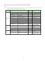
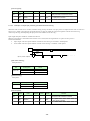
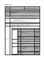
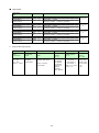
■ Revision history
Version
Date
Ver.1.0
Ver.2.0
2015. 5.19
2015. 7. 7
Contents
・Modified as below.
Delete [Note] of Y-axis in 1.1.2.
Contents of 4.2.5.9 Controller Reset.
[Note] of 5.2.2 Interpolation command
[Note] of 5.2.2 Interpolation command
[Note] of 5.2.2 Interpolation command
Add a table of 6.5.7 Regarding Speed
LNI.
CWI.
CCW.
Change during Motor Rotation.
Introduction
Prior to use, read this operation manual carefully to fully understand for correct use and follow all the instructions given in this manual. We shall be
exempted from taking responsibility and held harmless for damage or losses incurred by the user if the user fails to observe the instructions. Keep this
manual handy for future reference.
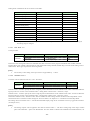
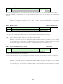
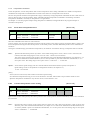
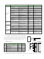
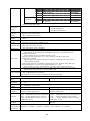
■ Checking the contents
When you unpack the package, check for the following accessories. If something is missing or broken, contact the place of purchase.
Product name
Model / Spec
Unit
MD5230D/MD5130D
Power Connector
XW4B-03B1-H1 (Omron) or equivalent
Motor Connector
XW4B-05B1-H1 (Omron) or equivalent
Connector for parallel control
20P MIL standard compliant connector
Connector for axis sensor
16P MIL standard compliant connector
USB cable
1.5m
Heat sink(optional)
*Software CD-ROM
MD51_52 Operation Tool
*comes with one software CD-ROM at the first purchase.
MD5130D
1
1
1
1
1
1
-
1
M5230D
1
1
2
1
2
1
1
1
The descriptions of this manual may change without notice because of the progress of the technologies, etc. Please download the up-date data from
our website (http://www.novaelec.co.jp/eng) and/or ask us to supply you directly.
Windows, Windows XP, Windows Vista, Windows 7 and Windows 8.1 are registered trademarks of Microsoft Corporation.
■ CE marking
This product complies with the following EU Directives.
EMS: EN61000-6-2 / EMI: EN61000-6-4
[Note]
•
The product complies with the EMC Directive; however, the customers’ machines and whole apparatus shall be tested for EMC
conformity by themselves.
■ RoHS Directive
This product complies with RoHS Directive 2011/65/EU.
Safety Notice
WARNING
■ General
This product is not designed or intended to be fail-safe, or for use in any application requiring fail-safe performance, such as in life-support or
safety devices or systems that could lead to death, personal injury or severe property or environmental damage (individually and collectively,
"critical applications"). Customer must be fully responsible for the use of this product in critical applications.
Do not use the product in potentially explosive, flammable, corrosive, wet, dusty or direct sunlight environments.
Person with expertise shall perform installation, connection and inspection.
Do not install, connect, inspect or move the product during power supply, be sure to turn off the power.
Stepper motor may step out at stop or during driving depends on conditions of use. In particular, objects being conveyed are subject to fall when
step out occurs during up-and-down driving. Ensure that it is thoroughly-tested under load conditions to be used and can be driven securely.
There is a possibility that the temperature of a connected motor becomes high even within rated current. Adjust the current value or operation
interval so as not to exceed the temperature tolerance prescribed by manufacturer.
-i-
■ Connection
Make sure the power input voltage is within the rated range. Otherwise it may cause fire or damage of the product.
Connect according to the connection diagram correctly and be sure to tighten terminal screws.
Do not bend, pull or pinch the power supply line or motor lead and signal wires excessively. Otherwise it may cause fire or damage of the
product.
■ Disassemble and Repair
Do not disassemble, repair and modify the product. Otherwise, it may cause fire or injury. Please contact us for inspection and repair.
CAUTION
■ General
Be very careful if you touch the product during power-on or for some time after power-off, the surface temperature of the product may become
high.
■ Placement
Please set it up to incombustibles such as metal.
■ Operation
When driving continuously, the surface temperature of the product may become high. Be sure not to exceed the surface temperature of 70°C.
Provide a means to stop for emergency anytime during operation. Otherwise, breakage or injury may result.
During operation, do not touch the rotating body or moving body connected to a motor with your hand, body or anything else.
When you move a rotation axis of a motor by your hand (such as manual positioning), turn off the power, or switch off the excitation and turn off
the current to a motor.
Provide an emergency stop measure or circuit outside the product to securely function in case abnormality of an external power supply,
disconnection of a signal line or the driver failure occurs.
If abnormality occurs, stop the use immediately and turn off the power.
■ Disposal
When discarding the product, handle it as industrial waste.
- ii -
1. Outline ......................................................................... 1
1.1.
Basic Circuit Block Diagram ................................................................................................................................ 2
1.1.1.
MD5130D ....................................................................................................................................................................... 2
1.1.2.
MD5230D ....................................................................................................................................................................... 3
1.2.
Part Name and Function ..................................................................................................................................... 4
1.2.1.
MD5130D ....................................................................................................................................................................... 4
1.2.2.
MD5230D ....................................................................................................................................................................... 5
1.3.
Connection Example ........................................................................................................................................... 6
1.4.
How to start motor control ................................................................................................................................... 7
2. Placement ................................................................... 8
2.1.
Installation Place .................................................................................................................................................. 8
2.2.
Installation Interval ............................................................................................................................................... 8
2.3.
Installation ............................................................................................................................................................ 9
2.3.1.
Installation by DIN rail..................................................................................................................................................... 9
2.3.2.
Installation by screws ..................................................................................................................................................... 9
3. Setup to PC............................................................... 10
3.1.
Operating Systems ............................................................................................................................................ 10
3.2.
Software Configuration ...................................................................................................................................... 10
3.3.
USB Driver Installation ...................................................................................................................................... 10
3.4.
MD51_52 Operation Tool Installation ............................................................................................................... 15
3.5.
USB Driver Uninstallation .................................................................................................................................. 18
3.6.
MD Operation Tool Uninstallation ..................................................................................................................... 19
4. MD51_52 Operation Tool ......................................... 20
4.1.
How to start MD51_52 Operation Tool ............................................................................................................. 20
4.2.
Main Window ..................................................................................................................................................... 22
4.2.1.
Connection Status ........................................................................................................................................................ 23
4.2.2.
Position Status.............................................................................................................................................................. 23
4.2.3.
Speed select................................................................................................................................................................. 24
4.2.3.1 Speed5Edit..................................................................................................................................................................25
4.2.4.
Automatic Home Search.............................................................................................................................................. 25
4.2.5.
Jog Operation Window:Jog....................................................................................................................................... 26
4.2.5.1
4.2.5.2
4.2.5.3
4.2.5.4
4.2.5.5
4.2.5.6
4.2.5.7
4.2.5.8
Jog Mode Select:Scan, Continuous, Preset ...........................................................................................................26
Drive Pulse for Preset:Preset ..................................................................................................................................26
Drive Status:Drive ....................................................................................................................................................26
Motor Rotation Start button and XY Coordinates Screen ..........................................................................................27
Stop .............................................................................................................................................................................28
ABS Position Set ........................................................................................................................................................28
Split Pulse ...................................................................................................................................................................28
Excitation OFF:Motor Free ......................................................................................................................................28
- iii -
4.2.5.9 Controller Reset ..........................................................................................................................................................29
4.2.6.
Menu............................................................................................................................................................................. 30
4.2.6.1
4.2.6.2
4.2.6.3
4.2.6.4
4.3.
File Menu ....................................................................................................................................................................30
Display Menu ..............................................................................................................................................................31
Configure Menu ..........................................................................................................................................................32
Help Menu...................................................................................................................................................................32
Configuration Settings window:Configuration................................................................................................ 33
4.3.1.
Mode Settings tab:Mode ........................................................................................................................................... 33
4.3.1.1
4.3.1.2
4.3.1.3
4.3.1.4
4.3.1.5
4.3.1.6
4.3.1.7
4.3.1.8
4.3.1.9
4.3.1.10
4.3.2.
4.3.2.1
4.3.2.2
4.3.2.3
4.3.2.4
4.3.2.5
4.3.3.
4.3.3.1
4.3.3.2
4.3.3.3
4.3.3.4
4.3.3.5
4.3.3.6
4.3.3.7
4.3.3.8
4.3.4.
4.3.4.1
4.3.4.2
4.3.4.3
4.3.4.4
4.3.4.5
4.3.4.6
4.3.5.
Run Current ................................................................................................................................................................34
Rest Current................................................................................................................................................................35
Step Resolution...........................................................................................................................................................35
Auto Current Reduction ..............................................................................................................................................35
Hardware Limit Stop Mode and Active Leve3 ............................................................................................................35
Software Limit and Stop Mode ...................................................................................................................................36
End Pulse....................................................................................................................................................................36
Step Out Detection and Detecting Timing ..................................................................................................................36
Power On Home Search Start ....................................................................................................................................37
Power On Program Start ..........................................................................................................................................37
Speed Settings tab:Speed......................................................................................................................................... 38
Mode ...........................................................................................................................................................................40
Start Speed..................................................................................................................................................................40
Drive Speed ................................................................................................................................................................40
Acceleration Time .......................................................................................................................................................40
Deceleration Time .......................................................................................................................................................41
Parameter Settings tab:Parameter ........................................................................................................................... 42
Post Timer 1~3............................................................................................................................................................43
Software Limit +/- ........................................................................................................................................................43
End Pulse Width .........................................................................................................................................................44
Pulse Scale Numeration and Denomination ..............................................................................................................44
Encoder Scale Numeration and Denomination .........................................................................................................45
Step Out Differential ....................................................................................................................................................46
Home Search Low Speed ..........................................................................................................................................46
Home Search Offset ...................................................................................................................................................46
Home Search Mode Settings tab:Home Search Mode............................................................................................ 47
Sensor Signal..............................................................................................................................................................48
Home Signal Level (HOME) .......................................................................................................................................48
Encoder Z-phase Signal Level (ECZ) ........................................................................................................................48
Step 1~4 Enable / Disable ..........................................................................................................................................49
Step 1~3 Search Direction..........................................................................................................................................49
Position Counter Clear................................................................................................................................................49
Split Pulse Settings tab:Split Pulse............................................................................................................................ 50
4.3.5.1 Split Length .................................................................................................................................................................51
4.3.5.2 Pulse Width .................................................................................................................................................................51
4.3.5.3 Pulse Count ................................................................................................................................................................51
4.3.6.
4.4.
Unit Name Settings tab:Unit Name ........................................................................................................................... 52
User Program Settings window:Program ...................................................................................................... 53
4.4.1.
User Program Display / Edit Area ................................................................................................................................ 54
4.4.2.
Edit Buttons .................................................................................................................................................................. 55
4.4.3.
Syntax Check ............................................................................................................................................................... 55
4.4.4.
Download / Upload / Open / Save ............................................................................................................................... 55
4.4.5.
Label for Moving........................................................................................................................................................... 56
- iv -
4.4.6.
Parameters Pane ......................................................................................................................................................... 56
4.4.7.
Run and Edit Mode Switching ..................................................................................................................................... 56
4.4.8.
Operation Pane ............................................................................................................................................................ 57
4.5.
Input / Output window:Input/Output ............................................................................................................... 58
4.6.
Real Position Display window:Encoder Position ........................................................................................... 60
4.7.
Configuration and Edit / Save User Program When Not in Connection ......................................................... 61
5. User Program ........................................................... 62
5.1.
Label................................................................................................................................................................... 63
5.1.1.
Program Label (P Label) .............................................................................................................................................. 63
5.1.2.
Jump Label (J Label).................................................................................................................................................... 63
5.1.3.
Subroutine Label (S Label) .......................................................................................................................................... 63
5.2.
User Program Commands ................................................................................................................................ 64
5.2.1.
Drive Commands ......................................................................................................................................................... 65
5.2.2.
Interpolation commands............................................................................................................................................... 70
5.2.2.1 Limitation on the coding with interpolation .................................................................................................................72
5.2.3.
Signal Output Commands ........................................................................................................................................... 73
5.2.4.
Program Control Commands....................................................................................................................................... 75
5.2.5.
Other Commands......................................................................................................................................................... 80
5.3.
Input/Output Ports.............................................................................................................................................. 81
5.4.
User Program Creation and Execution Rules .................................................................................................. 82
5.5.
Program Example using Label.......................................................................................................................... 83
5.5.1.
When making a jump to the head of a program.......................................................................................................... 83
5.5.2.
When writing the process of after condition branch to outside of normal operation (after END) ............................... 83
5.5.3.
When finishing the program at the jump destination after condition branch............................................................... 84
5.5.4.
When calling a subroutine............................................................................................................................................ 85
5.5.5.
Program Example by 2-Axis Simultaneous Command .............................................................................................. 86
5.5.6.
Program Example of Linear Interpolation .................................................................................................................... 86
5.5.7.
Program Example of Circular Interpolation ................................................................................................................. 87
5.5.8.
Program Example to execute Y axis from the program of X axis ............................................................................... 87
6. Additional Information on Function........................... 88
6.1.
Drive Pulse and Encoder Input ......................................................................................................................... 88
6.2.
Automatic Home Search ................................................................................................................................... 90
6.2.1.
6.2.1.1
6.2.1.2
6.2.1.3
6.2.1.4
The Description of Automatic Home Search Operation .............................................................................................. 90
Step 1 High-speed Home Search ..............................................................................................................................90
Step 2: Low-speed home search ...............................................................................................................................91
Step 3: Low-speed Encoder Z-phase Search............................................................................................................92
Step 4: High-speed Offset Drive .................................................................................................................................92
6.2.2.
The Setting Items for Automatic Home Search ........................................................................................................... 93
6.2.3.
Automatic Home Search Operation and Setting Example ......................................................................................... 94
-v-
6.2.3.1 Example of Home search using a home signal .........................................................................................................94
6.2.3.2 Example of Home search using a limit signal ............................................................................................................95
6.2.3.3 Example of Home search using an encoder Z-phase signal ....................................................................................96
6.3.
Split Pulse .......................................................................................................................................................... 98
6.3.1.
The Description of Split Pulse ...................................................................................................................................... 98
6.3.1.1 Start of Split Pulse .......................................................................................................................................................98
6.3.1.2 Stop of Split Pulse .......................................................................................................................................................98
6.3.1.3 Stop Timing of Split Pulse ...........................................................................................................................................98
6.3.2.
Split Pulse Setting Items .............................................................................................................................................. 99
6.3.3.
Setting Example of Split Pulse ..................................................................................................................................... 99
6.3.3.1 Example of output split pulses by predetermined rotation angle ...............................................................................99
6.3.3.2 Example of output split pulses by predetermined axis driving.................................................................................100
6.4.
Step Out Detection Function ........................................................................................................................... 101
6.4.1
The Description of Step Out Detection Function ....................................................................................................... 101
6.4.2
Step Out Detection Function Setting Items ............................................................................................................... 101
6.4.3
Setting Example of Step Out Detection Function ...................................................................................................... 101
6.4.1.
How to Release Step Out Error ................................................................................................................................. 102
6.5.
Speed Setting .................................................................................................................................................. 103
6.5.1.
Constant Speed Driving ............................................................................................................................................. 103
6.5.2.
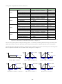
Trapezoidal Acceleration/Deceleration Driving (Trapezoid1, Trapezoid2, Trapezoid3) ........................................... 103
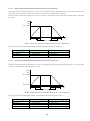
6.5.2.1 Simple Trapezoidal Acceleration/Deceleration Driving (Trapezoid1) ......................................................................104
6.5.2.2 Normal Trapezoidal Acceleration/Deceleration Driving (Trapezoid2)......................................................................104
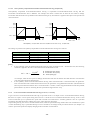
6.5.2.3 Non-symmetry Trapezoidal Acceleration/Deceleration Driving (Trapezoid3) .........................................................105
6.5.3.
S-curve Acceleration/Deceleration Driving (S-curve1, S-curve2) ............................................................................. 105
6.5.3.1 Simple S-curve Acceleration/Deceleration Driving (S-curve1) ................................................................................106
6.5.4.
Setting Items for Speed Control ................................................................................................................................. 107
6.5.5.
Motor Rotation Speed ................................................................................................................................................ 107
6.5.6.
Notes on Speed Settings ........................................................................................................................................... 107
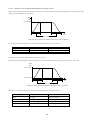
6.5.7.
Regarding Speed Change during Motor Rotation ..................................................................................................... 108
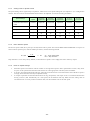
6.6.
Triangle Form Prevention Function ................................................................................................................ 108
7. Input/Output Signals ............................................... 109
7.1.
CN1 Power Connector .................................................................................................................................... 110
7.2.
CN2 Motor Connector ..................................................................................................................................... 110
7.3.
CN3 Parallel Control Connector ..................................................................................................................... 111
7.3.1.
Parallel Control Signals ............................................................................................................................................... 111
7.3.2.
Operation by Parallel Control Signals.........................................................................................................................112
7.3.2.1
7.3.2.2
7.3.2.3
7.3.2.4
7.3.2.5
7.4.
Starting Automatic Home Search ............................................................................................................................. 112
Scan Driving Operation ............................................................................................................................................ 112
Continuous Driving Operation .................................................................................................................................. 113
Program Driving Operation....................................................................................................................................... 113
Excitation OFF Operation ......................................................................................................................................... 114
CN4, CN7 Sensor Connector for Axis ............................................................................................................ 115
7.4.1.
CN4,CN7 Sensor Connector Signals .........................................................................................................................115
7.4.2.
Connection Example...................................................................................................................................................116
- vi -
7.4.2.1 Connection Example for Encoder ............................................................................................................................ 116
7.4.2.2 Connection Example for Over Limit and Home signal............................................................................................. 117
7.5.
CN5 USB Connector ....................................................................................................................................... 117
8. Package Dimensions ...............................................118
8.1.
MD5130D......................................................................................................................................................... 118
8.2.
MD5230D......................................................................................................................................................... 118
8.3.
Heat sink(Optional accessory for MD5230D)................................................................................................. 119
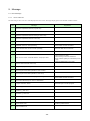
9. Message ................................................................. 120
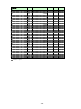
9.1.
Error Message ................................................................................................................................................. 120
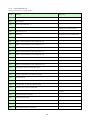
9.1.1.
Error Code List ........................................................................................................................................................... 120
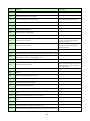
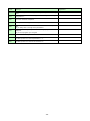
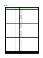
9.1.2.
Popup Message List .................................................................................................................................................. 122
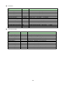
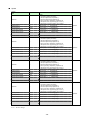
10. Specifications ...................................................... 125
Appendix A CSV File ............................................... 127
1. User Program File Configuration ........................................................................................................................ 127
1.1 【MD5130D】 ................................................................................................................................................................... 127
1.2 【MD5230D】 ................................................................................................................................................................... 129
2. Configuration Block [Configuration] .................................................................................................................... 133
3. Program Block [Program] .................................................................................................................................... 137
Appendix B User program....................................... 138
1. Example of continuous interpolation ................................................................................................................... 138
1.1 Continuous interpolation user program combined linear and circular ...........................................................................138
2. Example of circular interpolation ......................................................................................................................... 140
2.1 Circular interpolation user program ................................................................................................................................... 140
- vii -
1. Outline
MD5130D is 1-axis and MD5230D is 2-axis 5-phase stepper motor unit with bipolar pentagon drive, equipped with high
functions. A built-in EEPROM can program driving parameter values and the user program of up to 1000 steps for each axis.
The software “MD51_52 Operation Tool” is attached which can edit and register configuration data and a user program.
■ Integrated Motion Controller and Driver
MD5130D and MD5230D are the integrated motion controller with motion control function and microstep driver for 5-phase
stepper motor.
The user can easily set configuration and operations using the attached software.
■ Various Operations
Positioning, continuous driving, automatic home search and user program operations can be performed by using the attached
software from PC or parallel control signals.
■ User Program Function
The user can register various driving parameters and the user program of up to 1000 steps by 27 kinds of commands for
MD5130D and 36 kinds for MD5230D. Thereby the complex operation can easily be performed by registering them in advance.
■ Various Acceleration / Deceleration Drive Mode
There is various acceleration/deceleration driving: constant speed, trapezoidal acceleration/deceleration (symmetry/
non-symmetry) and S-curve acceleration/deceleration driving. In addition, a simple mode is available that does not require a
start speed setting.
■ Step Out Detection Function
If the differential between real position and logical position by an encoder signal is more than a specified value, it detects a step
out error.
■ Microstep
Microstep resolution is available 16 different resolutions, divided from 1 to 250.
■ Low Vibration Drive
Microstep driver with low vibration function achieves a smooth drive in low-speed driving.
Even when the setting value of Step Resolution is 16 or less (except 5, 10), this can reduce vibration in low-speed driving and
enables a smooth drive with less vibration.
■ Interpolation Function
Interpolation driving is operation that 2 axes move, interpolating the position every 1 drive pulse.
MD5230D can execute linear and circular interpolation. Linear interpolation is performed by setting the finish potision to the
current coordinates, and then writing the linear interpolation command according to the axis number. Circular interpolation is
performed by setting the center coordinates to the current coordinates (start point) and the finish coodinates, and then writing
CW or CCW circular interpolation command.
■ Continuous Interpolation
Continuous interpolation can also be executed that performs a series of interpolation processes such as linear interpolation →
circular interpolation → linear interpolation → ··· without stopping. It can be performed by continuously writing the
interpolation commands in user program.
-1-
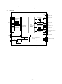
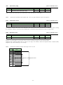
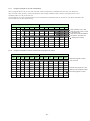
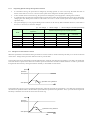
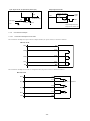
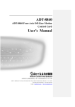
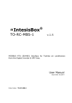
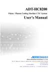
1.1. Basic Circuit Block Diagram
The follows show the MD5130D and MD5230D basic circuit block diagrams.
1.1.1.
MD5130D
CN4
5VEX
CN3
RESET
HOME
START
STOP
X
Y
Parallel
PSL0~5
Control
MODE0,1
Photo Coupler
High speed
Photo Coupler
XECA
TLP118
Encoder A-phase
XECB
Encoder B-phase
Photo Coupler
TLP291
XECZ
TLP291
XDRIVE Output Buffer
YDRIVE
DTC023YEB
XERROR
YERROR (Open collector)
Single Chip
Microcomputer
H8SX/1655
Motion
Control IC
MCX501
Photo Coupler
TLP291
XHOME
XLMT+
XLMTEMG
XIN0,1
Output Buffer
DTC023YEB
VEX
External Power
Output (+5V)
CN5
XOUT0,1
XSPLT
VEX
USB
Encoder Z-phase
Home
+Direction Limit
-Direction Limit
Emergency Stop
General Input 2 signals
General Output 2 signals
Split Pulse
External Power
Output (+24)
CN2
Motor Driving Circuit
CN1
Power Input
DC24V
FUSE
Power
Circuit
EEPROM
BR24T256-W
Microstep
Bipolar Pentagon Drive System
5A
VEX
MD5130D Circuit Block Diagram
-2-
5-phase Motor Output
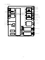
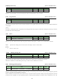
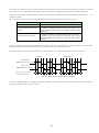
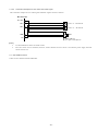
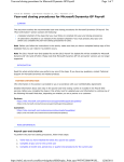
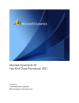
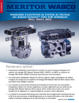
1.1.2.
MD5230D
X-axis sensor
CN3
Parallel
Control
RESET
HOME
START
STOP
X
Y
High speed
Photo Coupler
TLP118
Photo Coupler
5VEX
Photo Coupler
TLP291
MODE0,1
XDRIVE
Output Buffer
XERROR
Single Chip
Microcomputer
Motion
Control IC
H8SX/1655
MCX514
Photo Coupler
TLP291
DTC023YEB
YDRIVE
YERROR (Open collector)
YERROR
Encoder A-phase
XECB
Encoder B-phase
XECZ
XHOME
XLMT+
XLMTEMG
XIN0,1
Output Buffer
DTC023YEB
VEX
XOUT0,1
XSPLT
VEX
CN5
External Power
Output (+5V)
XECA
TLP291
PSL0~5
CN4
Encoder Z-phase
Home
+Direction Limit
-Direction Limit
Emergency Stop
General Input 2 signals
General Output 2 signals
Split Pulse
External Power
Output (+24)
Y-axis sensor
CN7
USB
CN1
Power Input
DC24V
FUSE
(same as X-axis)
Power
Circuit
Y-axis I/O signal
8A
VEX
CN2
X-axis Motor Driving Circuit
Microstep
X-axis
5-phase Motor Output
Bipolar Pentagon Drive System
SRAM
256KX16bit
CN6
Y-axis Motor Driving Circuit
(same as X-axis)
EEPROM
256Kbit
MD5230D Circuit Block Diagram
-3-
Y-axis
5-phase Motor Output
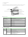
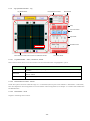
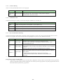
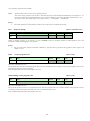
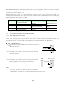
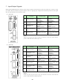
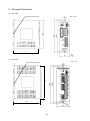
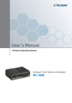
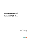
1.2. Part Name and Function
1.2.1.
MD5130D
The following shows the appearance of the MD5130D, its package dimensions are 108mm (H)×34mm (W)×95.5mm (D).
Input/output connectors are placed on the front panel and the rear panel is equipped with DIN rail installing hook.
Power LED
ID Setting Switch
Drive/Error LED
CN5 USB Connector
CN3: Parallel Control Connector
CN4 Axis Sensor Input/Output
Signal Connector
108mm
DIN Lever
CN2 Motor Connector
CN1 Power Connector DC24V
95mm
34mm
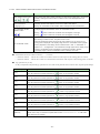
■ Connector / LED
Name
Contents
Power LED (Green)
Lights up during power-on.
Drive/Error LED (Red)
Lights up during motor rotation. When driving end pulse is enabled, it lights
up from a start of motor rotation until driving end pulse is OFF.
Please refer to Drive/Error LED DIsplay below.
ID Setting Switch
Set the unit ID number 0~F when two or more products are connected to one
PC.
(Factory default: 0)
CN1 Power Connector
Connected to 24V power source.
(Please refer to 7.1)
CN2 5-Phase Stepper Motor Connector
Connect a motor.
(Please refer to 7.2)
CN3 Parallel Control Connector
Connect a parallel control signal.
(Please refer to 7.3)
CN4 Sensor Connector
Connect a limit sensor signal, an encoder signal.
(Please refer to 7.4)
CN5 USB Connector
Connected to PC with USB cable.
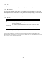
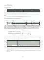
■ Drive/Error LED Display
State
During motor
rotation
LED
ON
Blinks at 1-second
intervals
Error
Blinks at 0.2-second
intervals
Contents
・Lights up during motor rotation.
*When driving end pulse is enabled, it lights up from a start of motor rotation
until driving end pulse is OFF.
・User program error from Host PC occurs.
・Parallel user program error occurs.
・Hard / Software limit error occurs.
・Error by emergency stop signal (EMG) occurs.
・Step out error occurs.
・Automatic home search error occurs.
・EEPROM access error occurs.
-4-
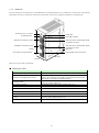
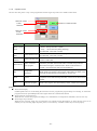
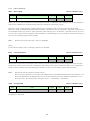
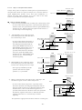
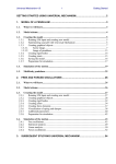
1.2.2.
MD5230D
The following shows the appearance of the MD5230D, its package dimensions are 130mm (H)×46.5mm (W)×98.5mm (D).
Input/output connectors are placed on the front panel and the rear panel is equipped with DIN rail installing hook.
Drive/error LED(X,Y axis)
Power LED
ID Setting Switch
CN5 USB connector
CN2 Motor Connector (X axis)
CN4 Axis Sensor Input/Output Signal
Connector (X axis)r
CN6 Motor Connector(Y axis)
CN7 Axis Sensor Input/Output Signal
Connector (Y axis)r
130mm
DIN Lever
CN3 Parallel Control Connector
CN1 Power Connector DC24V
98.5mm
46.5mm
Heat sink can optionally be mounted.
■ Connector / LED
Name
Contents
Power LED (Green)
Lights up during power-on.
Drive/Error LED (Red) (X and Y-axis)
Lights up during motor rotation. When driving end pulse is enabled, it
lights up from a start of motor rotation until driving end pulse is OFF.
Please refer to Drive/Error LED DIsplay below.
ID Setting Switch
Set the unit ID number 0~F when two or more products are connected
to one PC. (Factory default: 0)
CN1 Power Connector
Connected to 24V power source. (Please refer to 7.1)
CN1 Power Connector (X-axis)
Connected to 24V power source. (Please refer to 7.1)
CN3 Parallel Control Connector
Connect a parallel control signal.(Please refer to 7.3)
CN4 Sensor Connector (X-axis)
Connect a limit sensor signal, an encoder signal. (Please refer to 7.4)
CN5 USB Connector
Connected to PC with USB cable.
CN6 5-Phase Stepper Motor Connector
(Y-axis)
Connect a motor. (Please refer to 7.2)
CN7 Sensor Connector (Y-axis)
Connect a limit sensor signal, an encoder signal. (Please refer to 7.4)
-5-
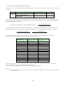
■ Drive/Error LED Display
State
During motor
rotation
LED
ON
Blinks at 1-second
intervals
Error
Blinks at
0.2-second
intervals
Contents
・Lights up during motor rotation.
*When driving end pulse is enabled, it lights up from a start of motor
rotation until driving end pulse is OFF.
・User program error from Host PC occurs.
・Parallel user program error occurs.
・Hard / Software limit error occurs.
・Error by emergency stop signal (EMG) occurs.
・Step out error occurs.
・Automatic home search error occurs.
・EEPROM access error occurs.
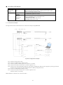
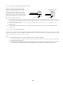
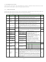
1.3. Connection Example
The figure shown below illustrates the basic connection example using MD5230D.
System Configuration Example
CN1:
CN2:
CN3:
CN4:
CN5:
Connect to 24V power source.
Connect a 5-Phase stepper motor (X-axis).
Connect a parallel control signal such as a PLC or switches.
Connect an encoder, a limit sensor or a home signal (X-xis).
Connect to PC with USB cable and the user can register configuration data and a user program, operate jog feed and
perform a user program using the attached software “MD51_52 Operation Tool”.
CN6: Connect a 5-Phase stepper motor (Y-axis).
CN7: Connect an encoder, a limit sensor or a home signal (X-axis).
Encoder:Connect as necessary
MD5130D has no connector for Y-axis(CN6 and 7).
-6-
1.4. How to start motor control
To start MD5130D and MD5230D motor control, follow the steps below.
(1) MD51_52 Operation Tool and USB Driver Installation
MD51_52 Operation Tool is the software to register configuration data and a user program to the unit. The user can install it
from the attached CD-ROM, or download and install from HP. Please refer to chapter 3 for how to install the software and driver,
and chapter 4 for how to operate MD51_52 Operation Tool.
(2) Configuration and User Program Registration
Connect the unit and PC with USB cable and set configuration data by MD Operation Tool and then create a user program. The
setting data and created program are written into built-in EEPROM of the unit.
(3) Placement and Wiring
Place the unit and connect wires to proper peripheral equipment. For the placement of this product, please refer to chapter 2, and
for the details of each connector and input/output signals, please refer to chapter 7.
(4) Start Motor Control
To start motor control in MD5130D and MD5230D, there are 3 ways as follows.
Control by using MD51_52Operation Tool
Connect the unit and PC with USB cable, and the user can perform manual operations such as jog feed, home search and
program execution.
Control by parallel control signals
Connect a PLC or switches to parallel control connector, and the user can operate it. Please refer to chapter 7 for more
details.
Control by communication command
MD5130D and MD5230D have communication commands. The user can create your own software with these commands and
control a motor.
For more details, please refer to the attached “MD5130D/MD5230D Communication Command User’s Manual”.
-7-
2. Placement
This chapter describes how to place the unit and the location to be placed.
2.1. Installation Place
MD5130D and MD5230D are designed and manufactured for the equipment that is used indoors. Be sure to set up in a proper
location as described below.
Indoor (location out of direct sunlight)
Location with no explosive, flammable and corrosive fluid or gas.
Ventilated location where is not filled with heat.
Location where the temperature is within 0 ~ 40°C (no freezing) and humidity is within 0 ~ 85% (no condensation).
Location where water (water drop), oil (oil drop) and any other liquid is not splashed.
Location with less dust, dirt and any other powder.
Location not exposed to vibration and shock.
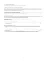
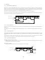
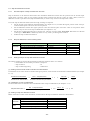
2.2. Installation Interval
When you set up this product, keep the product 20mm or more away from other equipment or structures. Make sure to install it
vertically (in a vertical position), or heat dissipation effect will be reduced. The product is natural convection cooling, so install
it to prevent heat accumulation.
MD5130D/MD5230D
20mm and over
MD5130D
20mm and over
20mm and over
When an optional heat sink is mounted in MD5230D, be sure to space 20mm away from the end of the heat sink.
-8-
2.3. Installation
MD5130D and MD5230D can be installed by using DIN rail or screws.
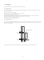
2.3.1.
Installation by DIN rail
Mount the hook on the back of the body to DIN rail and pull down the DIN lever of the body by a slotted screwdriver. And then
pull up the DIN lever, the body will be locked. To release the body, pull down the DIN lever by a slotted screwdriver, the body
will be released and the user can remove the body from DIN rail.
フック
Hook
DINレール
DIN rail
DIN lever
DINレバー
MD5230D installation is the same as MD5130D shown above.
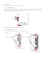
2.3.2.
Installation by screws
Fix the two points as shown below using M4 screws, pushing down DIN lever.
(1)MD5130D
Screwing points
(2)MD5230D
Screwing points
-9-
3. Setup to PC
This chapter describes how to setup to PC. To operate the unit from PC, install “USB driver” and the attached software
“MD51_52 Operation Tool”.
3.1. Operating Systems
MD5130D and MD5230D support the following OS.
・Windows 8.1 (32bit/64bit)
・Windows 7 (32bit/64bit)
・Windows Vista (32bit/64bit)
・Windows XP (32bit/64bit)
[Note]
•
To use “MD51_52 Operation Tool”, Microsoft .NET Framework 3.5 or greater needs to be installed.
3.2. Software Configuration
The software is available from the attached CD-ROM or for download
[USBDriver folder]
USB driver
├[32bit folder] ---------- 32bit OS USB driver
└[64bit folder] ---------- 64bit OS USB driver
[MDOPTOOL folder]
MD51_52 Operation Tool
├[32bit folder] ---------- 32bit OS installer
└[64bit folder] ---------- 64bit OS installer
The latest version is available on our web site: http://www.novaelec.co.jp/eng/index.html
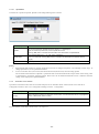
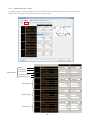
3.3. USB Driver Installation
To install USB driver for connecting the unit and PC, follow the steps below. The screenshots are on Windows 7 (32bit).
(1)
Turn on PC and the unit. DO NOT CONNECT them at this step.
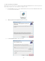
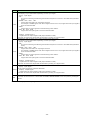
(2)
Make sure the PC is started and the unit is powered on. Then connect them with the attached USB cable.
The message shown below is displayed, then click “Click here for details.”.
- 10 -
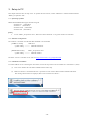
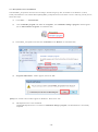
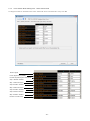
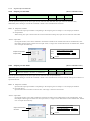
(3)
“Unknown device” is listed under “Other devices” in “Device Manager”, right-click on“Unknown device” and
choose “Update Driver Software…”.
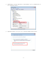
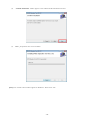
(4)
“Update Driver Software” window appears, then click “Browse my computer for driver software”.
- 11 -
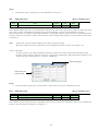
(5)
“Browse for driver software on your computer” window appears, then click “Browse…” button and select one of
the following driver folders.
・32bit OS : ¥USBDriver¥32bit
・64bit OS : ¥USBDriver¥64bit
Confirm the path to the folder you chosen, and then click “Next”.
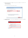
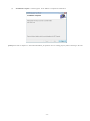
(6)
“Installing driver software…” window is displayed. If “Windows Security” window appears, click “Install this
driver rsoftware anyway”.
- 12 -
(7)
After installation is complete, you will see “Windows has successfully updated your driver software” window
appears. Then “Close” the window.
- 13 -
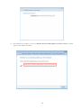
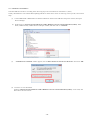
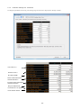
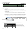
(8)
Check the driver software is successfully installed by the following steps:
Open “Device Manager” and check “NOVA electronics MD Series USB to RS232C Converter Virtual COM Port
(COMx)” is displayed under Ports (COM and LPT) (COMx denotes COM port number). Right-click on its icon or
text and choose “Properties”. If the driver is correctly installed, you can see “This device is working properly” in
the Device status field in “General” tab of “Properties” window.
- 14 -
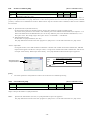
3.4. MD51_52 Operation Tool Installation
MD Operation51_52 Tool is the software to configure and operate MD5130D and MD5230D from PC. Follow the steps below to
install “MD51_52 Operation Tool”. The screenshots are on Windows 7 (32bit).
(1)
Execute SetupMD51_52_vJ5_2_x_xx.msi in MDOPTOOL¥32bit folder (for 64bit OS in MDOPTOOL¥64bit folder)
(* ”n” and ”m” are the release number.)
(2)
“MD51_52 Operation Tool Setup Wizard” appears, click “Next”.
(3)
On “Select Installation Folder” window, click “Next”.
- 15 -
(4)
“Confirm Installation” window appears. Click “Next” and the installation will start.
(5)
MD51_52 Operation Tool is now installed.
[Note] User account control window appears on Windows7. Please click “Yes”.
- 16 -
(5)
“Installation Complete” window appears. Click “Close” to complete the installation.
[Note] Please refer to chapter 4.1 and confirm the MD51_52 Operation Tool is working properly when connecting to the unit.
- 17 -
3.5. USB Driver Uninstallation
Uninstall USB driver from PC according to the following steps. The screenshots are on Windows 7 (32bit).
Usually uninstallation is not needed. When updating USB driver to the latest version or removing it from your PC, follow these
steps.
(1)
(2)
(3)
(4)
Connect MD5130D or MD5230D to be deleted USB driver and PC with USB cable and power on them, then open
Device Manager.
Right-click on “NOVA electronics MD Series USB to RS232C Converter Virtual COM Port(COMx)” under
Ports (COM and LPT) (COMx denotes COM port number) and then click on “Uninstall”.
“Confirm Device Uninstall” window appears, check “Delete the driver software for this device” then click “OK”.
The driver is now uninstalled.
Confirm “NOVA electronics MD Series USB to RS232C Converter Virtual COM Port(COMx)” is not listed, and
then remove the unit from PC.
- 18 -
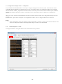
3.6. MD Operation Tool Uninstallation
Uninstall MD51_52 Operation Tool from PC according to the following steps. The screenshots are on Windows 7 (32bit).
Usually uninstallation is not needed. When updating MD51_52 Operation Tool to the latest version or removing it from your PC,
follow these steps.
(1)
(2)
Click “Start” → “Control Panel”
Click “Uninstall a program” link under the “Programs”, and “Uninstall or change a program” window appears.
(Click “Add or Remove Programs” if on Windows XP.)
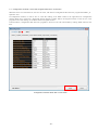
(3)
Select MD51_52 Operation Tool and click “Uninstall” (Click “Remove” if on Windows XP.)
(4)
“Programs and Features” window appears, then click “Yes”.
[Note] User account control window appears on Windows7. Please click “Yes”.
(5)
MD Operation Tool is now uninstalled.
Confirm MD Operation Tool is not listed in “Uninstall or change a program”, and uninstallation is successfully
completed.
- 19 -
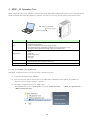
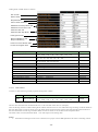
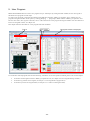
4. MD51_52 Operation Tool
MD51_52 Operation Tool is the software to configure and operate MD5130D and MD5230D from PC. After connecting the unit
and PC with USB cable and starting MD51_52 Operation Tool, the user can easily perform operations described as below.
USB cable (attached)
Window
Operation
Main
・Jog mode (Scan, Continuous, Preset)
・Automatic home search
・Invoking configuration and user program windows
・Download and upload configuration settings and a user program to a unit.
・Save and Load configuration settings and a user program to PC
Configuration
・Mode
・Speed
・Parameter
・Home search mode
・Split pulse
・Unit name
Program
・User program edit, download and upload to the unit, and execution
・Save and Load a user program in a file to PC
Input / Output
・Status display of input signals, setting of output signals
4.1. How to start MD51_52 Operation Tool
Start MD51_52 Operation Tool on your PC according to the following steps.
(1)
Connect the unit and PC with USB cable.
(2)
Turn on both power. If this is the first time to use MD5130D or MD5230D, install USB driver and MD51_52
Operation Tool according to the steps in chapter 3.
(3)
Start MD51_52 Operation Tool from “Start” menu.
On the Start menu, point to “All Programs”, then click “NOVA electronics” → “MD51_52 Operation Tool” →
“MD51_52 Operation Tool”.
- 20 -
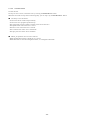
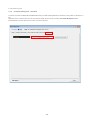
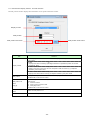
(4)
Select Connection Unit” window appears.
Select the “Unit ID” to connect, and then click “OK”.
* Unit ID is the identification number of each unit when two or more units are connected to PC. The ID number set by setting
switch on the front panel of the unit to being connected to PC is displayed. The default ID is 00.
Unit ID
If the connection is correctly established, all the data registered in the unit (configuration settings and a user program) will
be uploaded onto your PC and main window appears.
If the connection is not established, blank is displayed in Unit pull-down menu and MD Operation Tool is started in
“Unconnected” state.
- 21 -
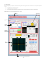
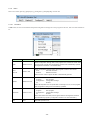
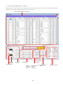
4.2. Main Window
When starting MD51_52 Operation Tool, the following main window appears. In this window, the user can perform operations
as below.
●
Jog mode (Scan, Continuous, Preset)
●
Automatic home search execution
●
Writing and reading configuration settings and a user program to/from the unit and save and load them.
In MD5130D, the axis used in MD Operation Tool is X-axis
Menu
Speed Select
Connection
Status
Position
Status
Automatic
Home Search
Jog
Operation
Window
Error code / message display pane
- 22 -
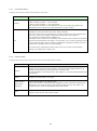
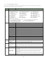
4.2.1.
Connection Status
It displays the connection status with the motion control unit.
Display
Condition
Contents
It displays the connection status with the motion control unit.
・Blue in the left is lighted ●:Unit connected
・Red in the right is lighted ●:Unit unconnected
Even though the connection is not established, the user can create user programs and
read/save files from a hard disc by using Open/Save in Program window.
It displays the unit ID and name of the unit to being connected.
When two or more units are connected to PC, the user can select from Unit pull-down menu
(click on ▼). If the unit is changed, configuration settings and a user program of
the unit to being connected will be uploaded to PC.
When blank in Unit pull-down menu is selected, communication is disconnected and the status
becomes unconnected state. If the status is “unconnected”, try to connect by selecting Unit ID
from Unit pull-down menu. After connection is established, configuration settings and a user
program will be uploaded from the unit automatically.
Unit
The Unit ID can be changed by the rotary switch of the unit. The unit can be named by
inputting in Unit Name tab in chapter 4.3.6.
4.2.2.
Position Status
It displays the current position (logical position) and speed during motor rotation.
Display
Contents
Position
Displays the current position (logical position). The user can set the logical position to an
arbitrary value by directly input, and press Enter in Position field.
This value depends on the scaling function. See chapter 4.3.3.4 Pulse Scale Numeration and
Denomination.
Speed
Displays the current speed in unit of pps.
Logical position
Sets the logical position to an arbitrary value.
Click on the axis button, and button will be highlighted in yellow and Position field becomes
editable state. Then input the value to set the logical position and click “Set” button, and
the logical position will be set and editable state will be cleared.
setting button
[Set] [X] [Y]
Clear
Clears Position field to 0.
However, it does not clear during motor rotation.
- 23 -
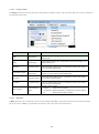
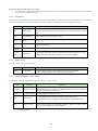
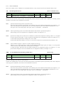
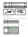
4.2.3.
Speed select
Select the speed to rotate a motor for jog mode. Speed1~4 uses the speed set by Speed Configuration. Speed5 can be freely
changed the speed during jog mode and motor rotation.
The button selected from 1 to 5 is highlighted in yellow.
Speed5 Select
Speed1~4
Speed5 Edit
Speed Parameters
Display
Contents
Selects the speed to rotate a motor for jog mode. Speed1~4 are the speed1~4 set by Speed
Speed1~4
settings tab in Configuration window, chapter 4.3.2.
In Speed Parameters fields, the setting value of selected speed is displayed.
Selects the speed5.
Drive speed for speed5 can be set by Speed5 Edit window in chapter 4.3.2.1.
Acceleration/deceleration mode and start speed use the setting value that is set in the speed1~4
Speed5
just before selecting the speed5.
The speed button just before selected is highlighted.
Speed5 can be changed the speed during driving; however, the speed can not be changed
during acceleration/deceleration when acceleration/deceleration mode is S-curve1 and S-curve
2.
Speed5 Edit
Sets the drive speed for speed5.
After selecting speed5, clicking “Edit” button opens Speed5 Edit window.
Displays each parameter setting for the speed currently selected.
Speed Parameters
When speed5 is selected, the drive speed set in Speed5 Edit window is displayed in “Drive
Speed”, and each parameter value just before selecting speed5 is displayed in “Mode”, “Start
Speed”, “Accel.Time” and “Decel.Time” fields.
- 24 -
4.2.3.1
Speed5Edit
It sets the drive speed for Speed5. Speed5 can be changed during motor rotation.
Display
Speed5
Contents
Set the drive speed for speed5 within the range of 1~500000(pps).
Input the value and press Enter, and the speed will be set.
Clicking (▲▼) button increases and decreases the value based on Speed5 Rate.
Speed5 Rate
Select Speed5 Rate from 1, 10, 100, 1000, 10000(pps).
When 10 is selected, clicking (▲▼) button increases and decreases the Speed5 value by
10(pps).
Close
Closes Speed5 Edit window.
[Note]
•
When Speed5 Edit window is opened, Speed Select can not be changed to Speed1~4 even though a motor stops. To
change Speed Select, close Speed5 Edit window.
As for acceleration time (Accel.Time) and deceleration time (Decel.Time) when selecting Speed5
The acceleration/deceleration of Speed5 is performed with acceleration/deceleration slope based on the setting value
in Speed Select just before selecting Speed5. Please note the acceleration/deceleration time is different from the
setting values displayed in Speed Parameters.
•
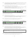
4.2.4.
Automatic Home Search
It performs an automatic home search. The mode and speed for an automatic home search must be set in each tab of
Configuration window, refer to 4.3 Configuration Settings window:Configuration.
Display
Contents
Axis [X]
Selects the axis to perform an automatic home search, the selected axis button is highlighted in
yellow. In MD5130D, select X button.
Run
Clicking the button starts an automatic home search.
Stop
Clicking the button stops an automatic home search.
For more details of Automatic Home Search, see chapter 6.2.
- 25 -
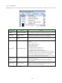
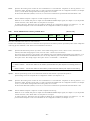
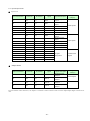
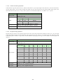
4.2.5.
Jog Operation Window:Jog
Jog Mode Select
Drive Pulse for Preset
Drive Status
Stop
Current Position
Set
Split Pulse
Excitation OFF
XY coordinates
Motor Rotation Start button and XY Coordinates Screen
4.2.5.1
Controller Reset
Jog Mode Select:Scan, Continuous, Preset
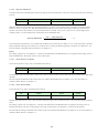
There are three modes can be set in main window. The selected mode button is highlighted in yellow.
Mode
Scan
Continuous
Preset
4.2.5.2
Contents
Rotates a motor only while pressing the motor rotation start button, and stops it after releasing
the button.
Starts a motor rotation when the motor rotation start button is clicked, and keeps it until Stop
button is clicked.
Rotates a motor by Preset value when the motor rotation start button is clicked.
Drive Pulse for Preset:Preset
Set the drive pulses for Preset within the range of 1~2147483646 (when in pulse scale numerator / denominator = 1000/1000)
This value depends on the scaling function. For more details of the scaling function, See chapter 4.3.3.4 Pulse Scale Numeration
and Denomination.
4.2.5.3
Drive Status:Drive
It lights in red during motor rotation.
- 26 -
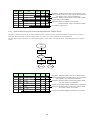
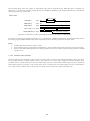
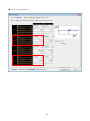
4.2.5.4
Motor Rotation Start button and XY Coordinates Screen
Display
Contents
Motor Rotation Start button
Motor rotation start button starts operations in selected jog mode (Scan / Continuous
/ Preset). Clicking the button starts to rotate a motor in the displayed axis and
direction.
Axis and Direction
It displays the axis and direction of the motor rotation start button.
Clicking XY coordinates screen rotation button changes the axis and direction.
[X] [Y] [+] [-]
XY Coordinates Screen
It changes the axis and direction of the XY coordinates screen.
Rotation button
Clicking
button rotates the coordinate axis 90 degrees to the right.
Clicking
button rotates the coordinate axis 90 degrees to the left.
The current position is displayed as a yellow circle on the XY coordinates screen.
After starting to rotate a motor, the yellow circle moves.
And when Graphics Position Tracing is set (see chapter 4.2.6.2), the locus of a
moving point is displayed. The display range of the XY coordinates screen (logical
XY coordinates screen
position) depends on the setting value of software limit + and - in “Parameter” in
chapter 4.3.3 – “Configuration”. The software limit range equals to the display range
of the XY coordinates screen regardless of software limit enable / disable.
The display range of the XY coordinates screen is always over ±230.
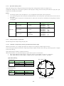
●
Indicate the direction of motor rotation (+/-) and axis.
・+direction rotation A motor axis rotates in clockwise direction with respect to the seating plane of a motor.
・-direction rotation A motor axis rotates in counterclockwise direction with respect to the seating plane of a motor.
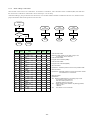
●
Jog operations by 10 key
・10 key on keyboard can perform jog operations as well, which can perform motor rotation start, stop and speed change.
10 key
6 key
4 key
8 key
2 key
Contents
This key performs the same operation as
button in Jog operation window.
This key performs the same operation as
button in Jog operation window.
This key performs the same operation as
button in Jog operation window.
This key performs the same operation as
button in Jog operation window.
9 key
This key performs the same operation as
button in Jog operation window.
This key performs the same operation as
button in Jog operation window.
3 key
1 key
This key performs the same operation as
button in Jog operation window.
This key performs the same operation as
button in Jog operation window.
7 key
0 key
It stops motor rotation.
It switches the speed select button.
Space key
While motor stops, it switches the speed select button 1→2→3→4→5→1→… in order each
time space key is pressed.
- 27 -
4.2.5.5
Stop
Clicking the axis button stops motor rotation.
However, while motor rotation is controlled by parallel control signals, the button in Stop pane does not work to stop
motor rotation.
4.2.5.6
ABS Position Set
The current position displayed in Position Status is set to the selected row of Program window (4.4.1 User Program
Display/Edit area) in the form of ABS command. Click the axis button the user wants to register the current position, and
it will be registered. This button will be enabled after Program window is opened. (4.2.6 Display menu).
Speed is set the speed selected in Speed Select (4.2.3) in Main window. Timer is set to 0 and EndP is set to OFF.
When the current position is set, the row selected in Program window moves to the next row.
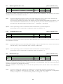
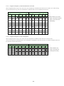
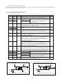
4.2.5.7
Split Pulse
Display
Contents
Select operation of split pulse from Split Pulse 1~4.
No.
As for the setting of split pulse, go to “Configure” menu → “Split Pulse”.
The button to enable split pulse.
When this button is pressed before motor rotation starts, split pulse will output at the start of
Axis button [X/Y]
motor rotation.
When this button is pressed during motor rotation, split pulse starts to output from that time.
While split pulse is enabled, the axis button is highlighted in yellow. When clicked again in an
enabled state, split pulse will be disabled and stop to output split pulses.
For more details of Split Pulse, see chapter 6.3.
4.2.5.8
Excitation OFF:Motor Free
Click the axis button in Motor Free, the excitation of the axis will turn OFF and the button will be highlighted in yellow.
When clicked again, it turns back ON. The excitation can not turn ON and OFF during motor rotation. While the excitation turns
OFF, the operation of motor rotation can not be performed.
- 28 -
4.2.5.9
Controller Reset
It resets the unit.
If a step out error occurs, release the error by clicking “Controller Reset” button.
When the user needs to stop motor rotation urgently, you can stop it by “Controller Reset” button.
■ The body is reset as follows.
・X and Y axes motor rotation stops instantly.
・X and Y axes user program operation stops.
・The logical/real position counters of X and Y axes are cleared to 0.
・The Speed Select of X and Y axes is set to 1.
・The Drive error of X and Y axes is cleared.
・The excitation of X and Y axes is turned ON.
・The split pulse of X and Y axes is disabled.
■ MD51_52 Operation Tool is reset as follows.
・When Speed5 Edit window is displayed, it is closed.
・When Run mode is selected in Program window, it is changed to Edit mode.
- 29 -
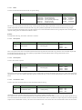
4.2.6.
Menu
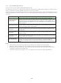
There are 4 menus, [File(F)], [Display(V)], [Configure(C)] and [Help(H)] on menu bar.
4.2.6.1
File Menu
In File menu, the user can download and upload configuration settings and a user program to the unit, and save and load them to
PC.
File menu
Function
Contents
Reads configuration settings and a user program from a saved file. When read
Open
Read from File
out from a file, Program and Configuration windows are automatically opened.
(Configuration window is in minimized state.)
Save
Save As
Save to File
Saves configuration settings and a user program to a file in CSV format.
Save
Overwrite and save
Save As
Rename and save
When saved to a file, Program window is automatically opened.
Reads data from a unit.
Program
User program
Upload
Read from Unit
Configuration
Configuration settings
All
All data
When MD Operation Tool is opened after connecting to a unit, a user program
and configuration settings are automatically uploaded.
Write data to the EEPROM of a unit.
Download
Write into Unit
Program
User program
Configuration
Configuration settings
All
All data
When Download is executed, User Program Edit and Configuration windows
are automatically opened. (Configuration window is in minimized state.)
Exit
Exit
Exits MD Operation Tool.
- 30 -
4.2.6.2
Display Menu
In Display menu, the user can open Program, Input/Output and Encoder Position windows, and change the unit of position.
Display menu
Function
Contents
Opens Program window, the user can edit, register and execute a
Program
Open Program window
Input/Output
Open Input/Output
window
Opens Input/Output window, the user can display input signal status
and operate output signals. See chapter 4.5 Input/Output.
Encoder Position
Open Encoder Position
window
Opens Encoder Position window. See chapter 4.6 Encoder Position.
user program in this window. See chapter 4.4 Program.
Changes the unit of position and moving distance from the following
4 options.
Pulse,mm,um,inch
[Items changed Position Unit]
・Main window:Position
・Main window:Preset
Position Unit
Change Position Unit*1
・Parameter window:Software Limit +
・Parameter window:Software Limit -
・Parameter window:Home Search Offset
Changing Position Unit does not perform the scaling function but
just change the display of unit. The scaling function for parameters
can be configured by the setting of pulse scale in Parameter
window. For more details of the setting of pulse scale, see chapter
4.3.3.4 Pulse Scale Numeration and Denomination.
Graphics Position
Tracing
Display Locus of Moving
Point *1
Graphics Grid
Display Grid Value *1
The moving position by motor rotation is displayed with dots in the
locus of a moving point.
[Note] During high-speed driving, the locus of a moving point
becomes coarse.
The value how many squares (grids) to move in the graphics
window. The moving amount of grids is determined based on the
software limit value in Parameter window.
*1 : A unit needs to be connected..
- 31 -
4.2.6.3
Configure Menu
In Configure menu, the user can open each window that can configure settings. And a unit name and reset to factory setting can
be performed in this menu.
Configure menu
Function
Contents
Mode
Mode setting
Opens Mode tab in Configuration window. See chapter 4.3.1 Mode
Settings tab.
Speed
Speed setting
Opens Speed Settings tab in Configuration window. See chapter 4.3.2
Speed Settings tab.
Parameter
Parameter setting
Opens Parameter Settings tab in Configuration window. See chapter
4.3.3 Parameter Settings tab.
Home Search Mode
Home Search
Mode setting
Opens Home Search Mode Settings tab in Configuration window. See
chapter 4.3.4 Home Search Mode Settings tab.
Split Pulse
Split Pulse setting
Opens Split Pulse Settings tab in Configuration window. See chapter
4.3.5 Split Pulse Settings tab.
Unit Name
Unit Name setting
Opens Unit Name Settings tab in Configuration window. See chapter
4.3.6 Unit Name Settings tab.
Factory setting
Reset to Factory
setting
Resets to factory setting.
Program
Clear all user programs.
Configuration Reset all settings of Configuration to factory setting.
All
4.2.6.4
Reset all data to factory setting.
Help Menu
In Help menu, the user can check the version of a unit firmware and MD51_52 Operation Tool in Version window, the upper
part is the version of MD51_52 Operation Tool and lower part is the version of a unit firmware
- 32 -
4.3. Configuration Settings window:Configuration
To operate MD5130D and MD5230D, it is necessary to configure settings based on the user system. Connect the unit and PC
with USB cable and start MD51_52 Operation Tool, the user can configure settings in Configuration window. From Configure
menu on menu bar of MD51_52 Operation Tool main window, the user can open 5 windows, which are Mode, Speed, Parameter,
Home Search Mode and Split Pulse windows. Each window can be switched by the tab in the upper part of Configuration
window.
When a unit is not connected, Download button works as Save button. This Save button saves configuration settings and a user
program.
For more details, please refert to chapter4.7 for Configuration and Edit / Save User Program When Not in Connection.
[Note]
•
4.3.1.
When configuration settings are changed, writing (download) in the unit is needed. Click Download button in the
bottom of Configuration window, and configuration settings in all tabs will be downloaded.
Mode Settings tab:Mode
It configures modes for driving. Each mode can be selected from a list by click ▼.
- 33 -
Setting items in Mode tab are as follows.
Run Curren
Rest Current
Step Resolution
Auto Current Reduction
Hardware Limit Stop Mode and
Hardware Limit Active Level
Software Limit and
Software Limit Stop Mode
Driving End Pulse
Step Out Detection and
Step Out Detecting
Power On Home Search Start
Power On Program Start
Display
Option
0.35, 0.42, 0.49, 0.56, 0.63,
0.91, 0.98, 1.05, 1.12, 1.19,
25, 30, 35, 40, 45, 50, 55,
65, 70, 75, 80, 85, 90, 95,
1, 2, 4, 5, 8,
10, 16, 20,
25, 40, 50, 80, 100, 125, 200, 250
Disable / Enable
Run Current [A]
Rest Current [%]
Step Resolution
Auto Current Reduction
Default
0.70,
1.26,
60,
100
0.77,
1.33,
0.84,
1.40
0.35[A]
50[%]
20
Enable
Hardware Limit Stop Mode
Instant / Slow
Instant
Hardware Limit Active Level
Low / High
Low
Software Limit
Disable / Enable
Disable
Software Limit Stop Mode
Slow / Instant
Slow
End Pulse
Disable / Enable
Disable
Step Out Detection
Disable / Enable
Disable
Step Out Detecting Timing
Drive End / While Drive
Drive End
Power On Home Search Start
Disable / Enable
Disable
Power On Program Start
Disable / Enable
Disable
* [ ] indicates a unit.
4.3.1.1
Run Current
It selects a value of driving current per phase during motor rotation.
Tab
Mode
Display
Run Current [A]
Option
Default
0.35,
0.42,
0.49,
0.56,
0.63,
0.70,
0.77,
0.84,
0.91,
0.98,
1.05,
1.12,
1.19,
1.26,
1.33,
1.40
0.35[A]
* [ ] indicates a unit.
The user can select one from 16 kinds from 0.35 to 1.40. The unit of the value is A (ampere).
This sets driving current of a motor during motor rotation. Please be sure to set it within the range of rating of a motor based on
the load. The greater a value of current is set, the larger motor torque becomes; however, the heat generation and vibration of
the unit and a motor become large. And the smaller a value of current is set, the more motor torque decreases.
The actual value of current fluctuates about ±5% with respect to the setting value.
[Note]
•
When the user changes a motor to be connected, set a proper value in MD Operation Tool before connecting a motor.
- 34 -
4.3.1.2
Rest Current
It selects a value of current during motor stop for when Auto Current Reduction is enabled.
Tab
Display
Option
Mode
Rest Current[%]
Default
25,
30,
35,
40,
45,
50,
55,
60,
65,
70,
75,
80,
85,
90,
95,
100
50[%]
Specify a value of current during motor stop by percentage to the setting value of Run Current, there are 16 kinds from 25 to
100, can be selected. The smaller a value of current is set, the more motor torque decreases.
4.3.1.3
Step Resolution
It selects a value of Step Resolution.
Tab
Mode
Display
Step Resolution
Option
1,
2,
4,
5,
8,
10,
16,
Default
20,
25, 40, 50, 80, 100, 125, 200, 250
20
Microstep resolution can be selected from 16 resolution settings from 1 to 250. This is the function to divide the basic step angle
of a motor into smaller microsteps. The basic step of 5-phase stepper motor is 500 steps per rotation and the rotation angle is
0.72°per step, so if 20 is set to Step Resolution, steps per rotation is 10000.
[Note]
•
4.3.1.4
Step resolution function is the method of dividing the basic step of motor excitation electrically. It does not assure that
the step angel divided by Step resolution is uniform mechanically.
Auto Current Reduction
It selects either Enable or Disable for Auto Current Reduction.
Tab
Mode
Display
Auto Current Reduction
Option
Disable/Enable
Default
Enable
Auto Current Reduction function suppresses the heat generation of a motor during motor stop by decreasing driving current
automatically while a motor is not rotating. Driving current will be the setting value of Rest Current automatically in 150ms
after motor stop.
[Note]
•
4.3.1.5
As the torque decreases during motor stop, be sure not to fall the object to be conveyed especially in up-and-down
driving, or it may cause damage to the equipment or injury.
Hardware Limit Stop Mode and Active Leve3
It selects a stop mode and logical level for active by a hardware limit signal.
Tab
Mode
Display
Hardware Limit Stop Mode
Hardware Limit Active Level
Option
Instant (Instant stop) / Slow (Deceleration
stop)
Low (GEX Short-circuited) / High (Open)
Default
Instant
Low
Limit input signals (XLMT+/–) for +/– direction are the #9, #10 pins in CN4 connector (see chapter 7.4 CN4 Sensor Connector
for Axis).
Hardware Limit Stop Mode selects either instant stop or deceleration stop for when this limit input signal becomes active.
Hardware Limit Active Level specifies the logical level for active. To make active for when an input signal and GEX are
short-circuited, set Low to Active level and to make active for when it is open, set High to Active level.
When a hardware limit error occurs, the user can escape from the limit area by rotating a motor in the reverse direction. The
- 35 -
hardware limit signal can also be used as the detection signal of automatic home search. See chapter 6.2 for more details of
automatic home search.
4.3.1.6
Software Limit and Stop Mode
It selects either Disable or Enable and a stop mode for Software Limit.
Tab
Display
Software Limit
Mode
Software Limit Stop Mode
Option
Disable / Enable
Default
Disable
Slow (Deceleration stop) / Instant (Instant
stop)
Slow
Software Limit is used to enable or disable the software limit function.
Software Limit Stop Mode selects either deceleration stop or instant stop for when motor rotation stop by the software limit
function.
Software Limit is the over run limit function which can internally set as position data, which differs from hardware limit signal
input such as an external sensor. If the logical position is over the setting value of software limit + during motor rotation in the +
direction, a software limit error occurs and motor rotation stop. Also if over the setting value of software limit– during motor
rotation in the – direction, a software limit error occurs and motor rotation stop.
When a software limit error occurs, the user can escape from the limit area by rotating a motor in the reverse direction.
The value of software limit can be set in “Software Limit +” and “Software Limit –” fields in Parameter tab (See chapter 4.3.3.2
Software Limit +/–).
[Note]
•
Software limit does not function even if enabled while a home search is running.
4.3.1.7
End Pulse
It selects either Enable or Disable to output driving end pulses at the end of driving.
Tab
Mode
Display
End Pulse
Option
Disable / Enable
Default
Enable
XDRIVE/END output signal for End Pulse is #15 pin in CN3 of the parallel control connector (see chapter 7.3).
For more details of Driving End Pulse, see chapter 7.3.1 Parallel Control Signals, the XDRIVE / ENDP in the table.
The value of end pulse width can be set in “End Pulse Width” field in Parameter tab (see chapter 4.3.3.3).
4.3.1.8
Step Out Detection and Detecting Timing
It selects either Enable or Disable of the step out detection function and the timing to detect step out.
Tab
Mode
Display
Option
Default
Step Out Detection
Disable / Enable
Disable
Step Out Detecting Timing
Drive End / While Drive
Drive End
Step Out Detection is used to enable or disable the step out detection function.
Step Out Detecting Timing selects the timing to detect step out. When “Drive End” is selected, and if it detects a position
deviation that is over the setting value of step out differential during motor stop, it becomes a step out error. When “While
Drive” is selected, and if it detects a position deviation that is over the setting value of step out differential during motor
rotation, it becomes a step out error and stops motor rotation immediately.
The value of step out differential can be set in “Step Out Differential” field in Parameter tab (see chapter 4.3.3.6). For more
details of Step Out Detection Function, see chapter 6.4.
- 36 -
4.3.1.9
Power On Home Search Start
It selects either Enable or Disable for automatic home search at power-on.
Tab
Mode
Display
Power On Home Search
Start
Option
Disable / Enable
Default
Disable
Power On Home Search Start is the function to automatically perform a home search when the power is on or the unit is reset by
the external RESET signal (see chapter 7.3) of the parallel control connector (CN3). For more details of Automatic Home
Search, see chapter 6.2.
Power On Home Search Start cannot be canceled during driving. Make sure to first stop driving by clicking “Controller Reset”
button in Main window, and next set to disable in “Power On Home Search Start” field in Mode tab.
[Note]
•
•
•
4.3.1.10
“Controller Reset” button in Main window does not start power on home search automatically.
When using Power On Home Search Start, it recommends to embed home search command into a program rather than
to use power on home search start.
In order to abort the operation by Power On Home Search Start, use “Controller Reset” button in Main window or
STOP signal of the parallel control connector (CN3) (See chapter 7.3).
Power On Program Start
It selects either Enable or Disable for automatic program start at power-on.
Tab
Mode
Display
Power On Program Start
Option
Disable / Enable
Default
Disable
Power On Program Start is the function to automatically perform program driving when the power is on or the unit is reset by
the external RESET signal (see chapter 7.3) of the parallel control connector (CN3).
To perform Power On Program Start, select Enable for power on program start and set MODE1, 0 signals of the parallel control
connector (CN3) to program driving mode (See chapter 7.3) and specify the program label number (see chapter 7.3.2.4) of a
user program to be executed by PSL0~5 signals (See chapter 7.3).
If Power On Home Search Start is also enabled, the program driving will be performed after completion of home search
execution.
Power On Program Start cannot be canceled during driving. Make sure to first stop the program by clicking “Controller Reset”
button in Main window, and next set to disable in “Power On Program Start” field in Mode tab.
[Note]
•
•
•
•
“Controller Reset” button in Main window does not start power on program start automatically.
When using Power On Program Start, write timer command to the first line of a program to be executed in advance, so
as to operate next command after passing the specified period.
In order to abort program driving by Power On Program Start, use “Controller Reset” button in Main window or STOP
signal of the parallel control connector (CN3) (See chapter 7.3).
In case the label number of a user program that is executed by PSL0~5 signals (see chapter 7.3.2.4) is not specified
(all OFF), the program label no.1 (P01) is automatically selected.
- 37 -
4.3.2.
Speed Settings tab:Speed
It configures Speed1~4, and the diagram of acceleration/deceleration mode currently selected is shown in the right of the
window. The setting range of each item is displayed in “Range of Value”
Mode
Start Speed
Speed Setting 1
Drive Speed
Acceleration Time
Deceleration Time
Speed Setting 2
Speed Setting 3
Speed Setting 4
- 38 -
Setting items in Speed tab are as follows in the table.
Display
Option / Range
Mode
Speed1
1 ~ 500000
(Blank)
Drive Speed [pps]
1 ~ 500000
4000
Acceleration Time [msec]
1 ~ 10000
(Blank)
Deceleration Time [msec]
1 ~ 10000
Constant/Trapezoid1/Trapezoid2/
Trapezoid3/S-Curve1/S-Curve2
(Blank)
1 ~ 500000
(Blank)
Drive Speed [pps]
1 ~ 500000
80000
Acceleration Time [msec]
1 ~ 10000
500
Deceleration Time [msec]
1 ~ 10000
Constant/Trapezoid1/Trapezoid2/
Trapezoid3/S-Curve1/S-Curve2
(Blank)
Start Speed [pps]
1 ~ 500000
(Blank)
Drive Speed [pps]
1 ~ 500000
80000
Acceleration Time [msec]
1 ~ 10000
500
Deceleration Time [msec]
1 ~ 10000
Constant/Trapezoid1/Trapezoid2/
Trapezoid3/S-Curve1/S-Curve2
(Blank)
Mode
Speed4
*1
Trapezoid1
Start Speed [pps]
Mode
Speed3
Constant
Start Speed [pps]
Mode
Speed2
Default
Constant/Trapezoid1/Trapezoid2/
Trapezoid3/S-Curve1/S-Curve2
S-Curve1
Trapezoid2
Start Speed [pps]
1 ~ 500000
4000
Drive Speed [pps]
1 ~ 500000
40000
Acceleration Time [msec]
1 ~ 10000
500
Deceleration Time [msec]
1 ~ 10000
(Blank)
*1:Speed4 is also used as the speed for high-speed home search and high-speed offset drive of automatic home search
operation. For more details of automatic home search, see chapter 6.2.
The user can register 4 patterns of the speed setting, Speed1 ~ 4. And each speed setting has the following items: Mode, Start
Speed, Drive Speed, Acceleration /Deceleration Time. Required setting items are different depends on the selecting mode.
The following figures show the acceleration / deceleration curves that the user can select from mode options, and setting items
that are required in each mode. For more details of each setting item, see chapter 6.5.
Speed
(pps)
Speed
(pps)
Drive Speed
Speed
(pps)
Drive Speed
Drive Speed
Start Speed
Time
(ms)
Constant Speed:Constant
Speed
(pps)
Drive Speed
Time
(ms)
Acceleration
Time
Simple Trapezoid:Trapezoid 1
Speed
(pps)
Drive Speed
Acceleration
Time
Time
(ms)
Normal Trapezoid:Trapezoid 2
Drive Speed
Speed
(pps)
Start Speed
Start Speed
Acceleration
Time
Deceleration
Time
Time
(ms)
Non-symmetry Trapezoid:Trapezoid 3
Acceleration
Time
Time
(ms)
Simple S-curve:S-Curve 1
- 39 -
Acceleration
Time
Time
(ms)
Normal S-curve:S-Curve 2
4.3.2.1
Mode
It selects acceleration/deceleration mode for speed setting.
Tab
Speed
Display
Option
Mode
Constant
Trapezoid1
Trapezoid2
Trapezoid3
S-Curve1
S-Curve2
Default
(constant speed)
(simple trapezoid)
(normal trapezoid)
(non-symmetry trapezoid)
(simple S-curve)
(normal S-curve)
Speed1:Constant
Speed2: Trapezoid1
Speed3:S-Curve1
Speed4: Trapezoid2
The user can select mode from the following: constant speed driving, simple trapezoidal acceleration/deceleration driving,
normal trapezoidal acceleration/deceleration driving, non-symmetry trapezoidal acceleration/deceleration driving, simple
S-curve acceleration/deceleration driving and normal S-curve acceleration/deceleration driving. Depend on the selecting mode,
required setting items are different described as below.
[NOTE]
In interpolation driving, the mode is limited to Constant.
4.3.2.2
Start Speed
Tab
Speed
Display
Start Speed
Range
1 ~ 500,000 [pps]
Default
Speed1:
Speed2:
Speed3:
Speed4:
-
-
-
4000
This is the speed at the start of acceleration/deceleration driving and at the end of driving, which is used in normal trapezoidal
acceleration/deceleration driving, non-symmetry trapezoidal acceleration/deceleration driving and normal S-curve
acceleration/deceleration driving.
4.3.2.3
Drive Speed
It sets a value of drive speed.
Tab
Speed
Display
Drive Speed
Range
1 ~ 500,000 [pps]
Default
Speed1:
Speed2:
Speed3:
Speed4:
4000
80000
80000
40000
Drive speed is the speed of constant speed period in constant and acceleration/deceleration driving. Set a value larger than start
speed; however, set a value smaller than start speed in constant driving. In all acceleration/deceleration modes, drive speed must
be set.
4.3.2.4
Acceleration Time
It sets a value of acceleration time for acceleration/deceleration driving.
Tab
Speed
Display
Acceleration Time
Range
1 ~ 10,000 [msec]
Default
Speed1:
Speed2:
Speed3:
Speed4:
-
500
500
500
Acceleration time is the time from start speed to drive speed (constant speed driving).
This must be set in all of acceleration/deceleration modes that perform acceleration/deceleration (except constant speed driving).
In acceleration/deceleration modes whose acceleration and deceleration time is symmetrical (simple trapezoid, normal trapezoid,
simple S-curve and normal S-curve), the value of acceleration time is also used as the value of deceleration time. The unit of the
- 40 -
setting value is milliseconds.
4.3.2.5
Deceleration Time
It sets a value of deceleration time for non-symmetry trapezoidal acceleration/deceleration driving.
Tab
Speed
Display
Deceleration Time
Range
1 ~ 10,000 [msec]
Default
Speed1:
Speed2:
Speed3:
Speed4:
-
-
-
-
Deceleration time is the time from drive speed (constant speed driving) to start speed.
This must be set in non-symmetry trapezoidal acceleration/deceleration driving. The unit of the setting value is milliseconds.
- 41 -
4.3.3.
Parameter Settings tab:Parameter
It configures parameters for driving. The setting range of each item is displayed in “Range of Value”.
Post Timer1~3
Software Limit +/End Pulse Width
Pulse Scale Numeration
and Denomination
Encoder Scale Numeration
and Denomination
Step Out Differential
HomeSearch Low Speed
Home Search Offset
- 42 -
Setting items in Parameter tab are as follows in the table.
Display
Range
Default
Post Timer 1 [msec]
1 ~ 65535
10
Post Timer 2 [msec]
1 ~ 65535
100
Post Timer 3 [msec]
1 ~ 65535
1000
Software Limit+
-2147483648 ~ 2147483647
*1
100000
Software Limit-
-2147483648 ~ 2147483647
*1
-100000
End Pulse Width [msec]
1 ~ 65535
100
Pulse Scale Numeration
1 ~ 65535
1000
Pulse Scale Denomination
1 ~ 65535
1000
Encoder Scale Numeration
1 ~ 65535
1000
Encoder Scale Denomination
1 ~ 65535
200
Step Out Differential
1 ~ 65535
100
Home Search Low Speed [pps]
1 ~ 500000
4000
Home Search Offset
-2147483646 ~ 2147483646
*1
100
*1:When pulse scale denominator = pulse scale numerator. If pulse scale denomination or numeration is changed,
the setting range is changed.
4.3.3.1
Post Timer 1~3
It sets post timer.
Tab
Parameter
Display
Range
Default
Post Timer1
1 ~ 65535 [msec]
10
Post Timer2
1 ~ 65535 [msec]
100
Post Timer3
1 ~ 65535 [msec]
1000
Post timer is the waiting time until next command starts after execution of user program commands such as ABS (Absolute
Position Move), INC (Relative Position Move), SST (Deceleration Stop) and IST (Instant Stop). The unit of the setting value is
milliseconds. Three types of post timer can be registered.
[Note]
•
The accuracy to the setting value of post timer is approximately ±1msec.
4.3.3.2
Software Limit +/-
It sets the value of Software Limit for + and – directions.
Tab
Parameter
Display
Software Limit +
Software Limit -
Range
-2147483648 ~ 2147483647
-2147483648 ~ 2147483647
Default
100000
-100000
Software Limit + is used to specify the value of logical position that functions as the software limit in the + direction. When the
logical position is over the value of software limit + during motor rotation in the + direction, it stops.
Software Limit – is used to specify the value of logical position that functions as the software limit in the – direction. When the
logical position is over the value of software limit – during motor rotation in the – direction, it stops.
To function Software Limit, “Software Limit” must be enabled in mode settings tab and “Software Limit Stop Mode” can be
selected from Slow or Instant in mode settings tab. For more details, see chapter 4.3.1.6 Software Limit and Stop Mode.
The setting values of software limit +/– become the maximum display range of XY coordinates screen in jog operation window
(see chapter 4.2.5).
[Note]
•
The setting of pulse scale is applied to the value of software limit +/–. The above setting range is the range of when
pulse scale numerator = pulse scale denominator. For more details of Pulse Scale Numeration and Denomination, see
- 43 -
chapter 4.3.3.4.
4.3.3.3
End Pulse Width
It sets End Pulse Width.
Tab
Parameter
Display
Range
1 ~ 65535 [msec]
End Pulse Width
Default
100
This sets end pulse width for end pulse output from XDRIVE/ENDP signal (see chapter 7.3) of the parallel control connector
(CN3) at the stop of motor rotation. The unit of the setting value is milliseconds.
To function End Pulse, “End Pulse” must be enabled in mode settings tab. For more details, see chapter 4.3.1.7 End Pulse.
[Note]
•
The accuracy to the setting value of end pulse width is approximately ±1msec.
4.3.3.4
Pulse Scale Numeration and Denomination
It sets the value of Pulse Scale Numeration and Denomination to perform scaling for position data.
Tab
Parameter
Display
Range
Pulse Scale Numeration (numerator)
Pulse Scale Denomination (denominator)
1~65535
1~65535
Default
1000
1000
Scaling function of pulse scale is the function to convert to the pulse value by multiplying all of the input position data by the
specified coefficient. This function allows the user to handle position data in a unit of mm or inch. “Pulse Scale Numeration”
field is to set the value of pulse scale numerator and “Pulse Scale Denomination” field is to set the value of pulse scale
denominator. MD5130D and MD5230D convert to the pulse value by multiplying the input/display position data by the
following coefficient (for more details of Drive Pulse, see chapter 6.1).
Drive Pulse Value =
Input Value ×
Displayed Value = Drive Pulse Value ×
P uls e Sc a le Num e rat o r
Pulse Scale Denominator
Pulse Scale Denominator
P uls e Sc a le Num e rat o r
For example, if 1 pulse of drive pulses is equivalent to 0.01mm of moving distance, to display position data in a unit of mm, set
100/1 to scale numerator/scale denominator. If input value 1(mm) is written, it converts to 100 pulses and 100 pulses are
displayed as 1.00. If calculation result is after the decimal point, it is rounded off up to the valid decimal place for 1 pulse and
then will be displayed. Position data which scaling is performed is as follows.
Window
[Note]
•
•
Position Data Performed Scaling
Main Window
Position display, Preset moving distance
Encoder Position Window
Encoder E-scale P-scale display
Configuration:Parameter Tab
Software Limit +/-,Home Search Offset
Program Window
ABS,INC,ABA,ICA,PJP,POS,WTP commands’ position data
The values of pulse scale numerator and denominator affect all the position data. Configure them at the beginning of
system development based on circumstances such as step resolution or ball screw pitch. Once configure values, do not
change them on the way.
The factory default of pulse scale numerator/denominator is 1000/1000, which indicates input/display equal to drive
pulse value.
- 44 -
4.3.3.5
Encoder Scale Numeration and Denomination
It sets the value of Encoder Scale Numeration and Denomination in order to perform scaling to the value counted by an encoder
input signal.
Tab
Display
Range
Encoder Scale Numeration (numerator)
Parameter
Encoder Scale Denomination
(denominator)
Default
1~65535
1000
1~65535
200
This settings are in order to match to the logical position (in a unit of pulse), where the count value of an encoder input signal
multiplied by the specified coefficient. This obtains the pulse conversion value of real position. For more details of Encoder
Input and count method, see chapter 6.1.
Converted pulses of real position = Encoder signal count value ×
Encoder Scale numerator
Encoder Scale denominator
The relationship between the pulse number of the encoder to be used per rotation and encoder scale numerator /denominator to
match the logical position and real position with respect to the setting value of step resolution can be calculated as follows.
Encoder Scale numerator
Encoder Scale denominator
=
500 × Step Resolution
Pulse Number per Rotation × 4
When the pulse number per rotation of the encoder is 500 pulses, the setting example of encoder scale numerator and
denominator with respect to the setting value of step resolution is as follows.
Encoder Scale
Encoder Scale
Numerator
Denominator
1
1000
4000
2
1000
2000
4
1000
1000
5
1000
800
8
1000
500
10
1000
400
16
1000
250
20
1000
200
25
1000
160
40
1000
100
50
1000
80
80
1000
50
100
1000
40
125
1000
32
200
1000
20
250
1000
16
Step Resolution
The factory default of encoder scale numerator and denominator is 1000/200, so when the pulse number per rotation of the
encoder is 500 pulses, real position counter counts 10000 per rotation.
If step resolution is changed, modify the value of encoder scale setting appropriately.
[Note]
•
When using Step Out Detection of chapter 6.4, be sure to match the logical position and real position by using this
function in advance.
- 45 -
4.3.3.6
Step Out Differential
It sets the limit value of the difference between the logical position and the pulse conversion value of real position for detecting
step out.
Tab
Parameter
Display
Range
Step Out Differential
Default
100
1~65535
When the difference between the logical position and pulse conversion value of real position exceed this value during motor
rotation, it occurs a step out error. Step Out Differential must properly be set based on the pulse number per rotation of the
encoder to be used or step resolution. If step out differential is too small, it may occur a step out error even though a motor
normally rotates. Use the formula below to determine the recommended value.
Step Out Differential ≧
500 × Step Resolution
Pulse Number per Rotation
× 4
To function Step Out Detection, set to enable Step Out Detection in mode tab (see chapter 4.3.1.8). If the user needs to perform
Step Out Detection during motor rotation, set to”While Drive” in Step Out Detecting Timing in mode tab (see chapter 4.3.1.8).
For more details of Step Out Detection Function, see chapter 6.4
[Note]
The setting of pulse scale (see chapter 4.3.3.4 Pulse Scale Numeration and Denomination) is not applied to the setting value of
Step Out Differential. The setting value is a unit of drive pulse.
4.3.3.7
Home Search Low Speed
It sets search speed for step 2, step 3 of automatic home search.
Tab
Parameter
Display
Home Search Low Speed
Range
1 ~ 500000 [pps]
Default
4000
To immediately stop search operation, set the lower value for home search low speed than start speed of home search high speed
(Speed4).
The action mode of automatic home search can be set in Home Search Mode tab (see chapter 4.3.4). For more details of
Automatic Home Search, see chapter 6.2.
4.3.3.8
Home Search Offset
It sets offset drive for step 4 of automatic home search.
Tab
Parameter
Display
Home Search Offset
Range
-2147483646 ~ 2147483646
Default
100
Home Search Offset drives in the + direction when setting a positive value, and drives in the – direction when setting a negative
value.
The setting of pulse scale (see chapter 4.3.3.4 Pulse Scale Numeration and Denomination) is applied to the setting value of
Home Search Offset. The above setting range is the range of when pulse scale numerator = pulse scale denominator.
The action mode setting of automatic home search can be set in Home Search Mode tab (see chapter 4.3.4). For more details of
Automatic Home Search, see chapter 6.2.
- 46 -
4.3.4.
Home Search Mode Settings tab:Home Search Mode
It configures modes for automatic home search. Each mode can be selected from a list by click ▼.
Sensor Signal
Home Signal Level (HOME)
Encoder Z-phase Signal Level (ECZ)
Step 1 Enable / Disable
Step 1 Search Direction
Step 2 Enable / Disable
Step 2 Search Direction
Step 3 Enable / Disable
Step 3 Search Direction
Step 4 Enable / Disable
Position Counter Clear
- 47 -
Setting items in Home Search Mode tab are as follows.
Display
Option
Default
Sensor Signal
Home / Limit
Home
Home Signal Level
Low / High
Low
Z Signal Level
Low / High
Low
Step1 Enable (High Speed Search)
Disable / Enable
Disable
Step1 Direction
+ / -
-
Step2 Enable (Fine Search)
Disable / Enable
Disable
Step2 Direction
+ / -
-
Step3 Enable (Encoder Z Search)
Disable / Enable
Disable
Step3 Direction
+ / -
+
Step4 Enable (Offset Move)
Disable / Enable
Disable
Position Clear
Disable / Enable
Enable
In Home Search Mode tab, the user can set the action mode of automatic home search. For more details of Automatic Home
Search, see chapter 6.2.
4.3.4.1
Sensor Signal
It selects a sensor signal for searching at step1 and 2.
Tab
Home Search
Mode
Display
Sensor Signal
Option
Home / Limit
Default
Home
Sensor Signal can be selected from either Home or Hardware Limit signal (see chapter 7.4).
Home signal is the #8 pin in CN4 connector. Limit signals of the + and – directions are the #9, #10 pins in CN4 connector (see
chapter 7.4 CN4 Sensor Connector for Axis). If Limit signal is selected, the limit signal of the search direction at step1 and 2
becomes the sensor signal.
4.3.4.2
Home Signal Level (HOME)
It selects an active logical level for HOME signal.
Tab
Home Search
Mode
Display
Home Signal Level
Option
Low (GEX Short-circuited)/ High
(Open)
Default
Low
Home signal is the #8 pin in CN4 connector (see chapter 7.4).
When an active logical level is set to Low, detection operation of step 1, 2 starts, and when Home signal becomes
short-circuiting with GEX, the operation takes the signal as active and then it stops. When set to High, and when Home signal
becomes open, the operation takes it as active and then it stops.
4.3.4.3
Encoder Z-phase Signal Level (ECZ)
It sets an active logical level for encoder Z-phase signal (ECZ) detected in step 3.
Tab
Home Search
Mode
Display
Option
Default
Z Signal Level
Low (GEX Short-circuited)/ High (Open)
Low
Encoder Z-phase signal (ECZ) is the #4 pin in CN4 connector (see chapter 7.4).
When an active logical level is set to Low, detection operation of step 3 starts, and when the signal becomes short-circuiting
with GEX, the operation takes the signal as active and then it stops. When set to High, and when the signal becomes open, the
- 48 -
operation takes it as active and then it stops.
4.3.4.4
Step 1~4 Enable / Disable
It sets to execute or not to execute each step of home search operation.
Tab
Home Search Mode
Display
Option
Default
Step1 Enable
Disable (non-execution) / Enable (execution)
Disable
Step2 Enable
Disable (non-execution) / Enable (execution)
Disable
Step3 Enable
Disable (non-execution) / Enable (execution)
Disable
Step4 Enable
Disable (non-execution) / Enable (execution)
Disable
When selecting Disable (non-execution), the step is not executed and proceeds with next step. When selecting Enable
(execution), search operations for each step are executed in the specified direction. See chapter 6.2.1 for more details on each
step.
4.3.4.5
Step 1~3 Search Direction
It selects a search direction for each step of home search operation.
Tab
Home Search Mode
Display
Option
Default
Step1 Direction
+ / -
-
Step2 Direction
+ / -
-
Step3 Direction
+ / -
+
When selecting +, search operation is executed in the + direction. And when selecting –, search operation is executed in the –
direction. The direction of high-speed offset driving at step 4 can be set in “Home Search Offset” field in Parameter settings tab
(see chapter 4.3.3.8).
4.3.4.6
Position Counter Clear
It selects to clear or not to clear the position counter at the end of automatic home search.
Tab
Home Search Mode
Display
Option
Position Clear
Disable (not clear) / Enable (clear)
When enabled, the logical and real positions are cleared to 0 at the normal end of automatic home search.
- 49 -
Default
Enable
4.3.5.
Split Pulse Settings tab:Split Pulse
It configures Split Pulse 1~4. The setting range of each item is displayed in “Range of Value”.
Split Length
Split Pulse
Settings 1
Pulse Width
Pulse Count
Split Pulse
Settings 2
Split Pulse
Settings 3
Split Pulse
Settings 4
- 50 -
Setting items in Split Pulse tab are as follows in the table.
Display
Range
Split Pulse 1
Split Pulse 2
Split Pulse 3
Split Pulse 4
Default
2 ~ 65535
Split length
Split Pulse 1
Pulse width
1 ~ 65534
5
Split pulse number
1~65535 or 0 (infinite)
0
Split length
2 ~ 65535
Split Pulse 2
Pulse width
1 ~ 65534
10
Split pulse number
1~65535 or 0 (infinite)
0
Split length
2 ~ 65535
Split Pulse 3
Pulse width
1 ~ 65534
500
Split pulse number
1~65535 or 0 (infinite)
10
Split length
2 ~ 65535
Split Pulse 4
Pulse width
1 ~ 65534
5000
Split pulse number
1~65535 or 0 (infinite)
10
The user can register 4 split pulse settings 1 ~ 4. Each split pulse setting has items that split length (cycle), pulse width and split
pulse number. For more details of Split Pulse function, see chapter 6.3.
4.3.5.1
Split Length
Tab
Split Pulse
Display
Split Length
Range
Default
Split
Split
Split
Split
2~65535
Pulse
Pulse
Pulse
Pulse
1
2
3
4
:
:
:
:
10
20
1000
10000
Split Length is the intervals from when split pulse is on to when next split pulse is on, and it can be specified by the drive pulse
number. The setting value must be a pulse width < a split length.
4.3.5.2
Pulse Width
It sets the pulse width of a split pulse.
Tab
Split Pulse
Display
Pulse Width
Range
Default
Split
Split
Split
Split
1~65534
Pulse
Pulse
Pulse
Pulse
1
2
3
4
:
:
:
:
5
10
500
5000
Pulse Width is the ON width of one pulse of split pulse output signal, and it can be specified by the drive pulse number.
The setting value must be a pulse width < a split length.
4.3.5.3
Pulse Count
It sets the output pulse number of split pulse.
Tab
Split Pulse
Display
Pulse Count
Range
Default
Split
Split
Split
Split
1~65535
or 0 (infinite)
Pulse
Pulse
Pulse
Pulse
1
2
3
4
:
:
:
:
0
0
10
10
Pulse Count is the number of output split pulse.
When 0 is set, it continues to output split pulses until stopped by jog operation window, split pulse stop command (PST) of a
user program, or motor rotation stops.
[Note]The setting of pulse scale (see chapter 4.3.3.4 Pulse Scale Numeration and Denomination) is not applied to each setting
value of split pulse. Even when setting Pulse Scale Numeration and Denomination, each setting value of split pulse must be set
- 51 -
in a unit of drive pulse.
4.3.6.
Unit Name Settings tab:Unit Name
It sets the unit name of MD5130D and MD5230D. Please use half-width alphanumeric characters and symbols 32 characters or
less.
When the unit is connected, the user can write the unit name into the unit by clicking “Unit Name Download” button.
Download button in other tabs does not work to write into the unit.
- 52 -
4.4. User Program Settings window:Program
Program window is used to display, edit, register and execute a user program. There are two modes: Edit mode that edits and
registers a user program, and Run mode that executes a user program.
User Program Display / Edit Area
Run and Edit Mode
Switching
Displays the file name of Open /
Label for
Moving
Axis selection
Operation
Open / Save
the file
Edit Buttons
Check
: Syntax Check
Download : Writing
Upload
: Reading
- 53 -
Close Program
window
Parameters Pane
4.4.1.
User Program Display / Edit Area
This is used to create and edit a user program. As shown in the table below, the user needs to configure each item. For more
details of User Program and Input / Output Ports, see chapter 5.
Item
Command
Label
Set program label (P01~P63), jump label (J01~J63) or subroutine label (S01~S19)
Cmd
Contents
Select command by click ▼.
ABS:Absolute position move
ICA:Relative position move start
IST:Instant stop
OTP:Output port ON Pulse
JMP:Unconditional jump
JSR:Subroutine jump
RED:Repetition end
WTE:Waiting driving end
SPD:Drive speed
ABA:Absolute position move start
CNT:Continuous move start
HOM:Home search
SSP:Split pulse start
IJP:Input condition jump
RET:Subroutine return
TIM:Timer
END:Program end
POS:Current position
INC:Relative position move
SST:Deceleration stop
OUT:Output port ON/OFF
PST:Split pulse stop
PJP:Position condition jump
REP:Repetition start
WTP:Waiting position passage
PAS:Pause for debug
NOP:No operation
【Commands only for MD5230D】
ABB:2-axis simultaneous absolute position move
ICB:2-axis simultaneous relative position move
HMB:2-axis simultaneous home search
LNI:2-axis linear interpolation move
CEN:Circular interpolation center setting
.
CWI:CW circular interpolation move
CCW:CCW circular interpolation move
Data
Speed
ABS, ABA, ABB
Absolute position move
INC, ICA, ICB
Relative position move
CNT
Direction(+/-)
LNI
X/Y linear interpolation finish position(Relative pulse number)
CWI, CCW
X/Y circular interpolation finish position(Relative pulse number)
CEN
X/Y circular center position(Relative pulse number)
OUT
Output port number ; Output state (ON / OFF)
OTP
Output port number ; Pulse width (1~65535msec)
SSP
Split pulse settings number (1~4)
JMP
Jump destination label
IJP
Input port number ; Signal level (Hi / Low) ; Jump destination label
PJP
Absolute position ; Jump destination label
JSR
Subroutine label
REP
Repetition number (1~255)
TIM
Waiting time (1~65535msec)
WTP, POS
Absolute position
SPD
Drive speed (1~500000)
Other Commands
Non-required
ABS, ABA, INC, ICA,
Select drive speed1~4 (see chapter 4.3.2). When inputting a selected command to the
CNTABB, ICB, LNI,
current line, it sets the same value as Speed value that the command is first found in the
CWI, CCW
upper than the current line. If not found, Speed:1 is set.
Other Commands
Non-required
Select post timer 1~3 (see chapter 4.3.3.1.). If not needed, select 0.
Timer
ABS, INC, SST, IST
When inputting a selected command to the current line, it sets the same value as Timer
ABB, ICB
value that the command is first found in the upper than the current line. If not found, Timer:0
is set.
Other Commands
Non-required
Select On to output end pulse and select Off not to output end pulse after the completion of
the command.
ABS, INC, HOM
EndP
ABB, ICB, HMB
When inputting a selected command to the current line, it sets the same value as EndP
value that the command is first found in the upper than the current line. If not found,
EndP:Off is set.
Note: When selecting On, End Pulse must be enabled in mode settings tab in Configuration
window.
Other Commands
Non-required
- 54 -
[Note] Handling of blank lines in a program
•
The blank line in a program is deleted and shifted up, and written into the unit at download. If the user keeps a blank
line, set NOP command to that line.
4.4.2.
Edit Buttons
The user can cut, copy and paste by these buttons in user program display / edit area. Also, the same operation can be performed
from right-click menu on user program display / edit area. These are available in Edit mode in Program window
Item
Function
Contents
Copies the selection to the clipboard and removes the selection from the display
Cut
Cut Selection
area. The selection should be a single cell or row, or continuous blocks of cells or
rows.
Copy
Copy Selection
Copies the selection to the clipboard. The selection should be a single cell or
row, or continuous blocks of cells or rows.
Paste
Paste
Pastes the contents of the clipboard to the selected cell below in the display
area.
Undo
Undo
Undoes the last action.
Delete Row
Deletes a selected row, the row of an active cell or continuous blocks of rows.
Insert Row
Inserts blank lines of the number of selected lines before the active row or cell.
Multiple lines can be inserted. The lines over 1000 will be deleted.
Line-Del
(Delete)
Line-Ins
(Insert)
4.4.3.
Syntax Check
It checks syntax error in a user program
Item
Check
4.4.4.
Function
Syntax Check
Contents
Performs syntax check in a user program. If syntax error is detected,
the error message appears and moves the focus to that line.
Download / Upload / Open / Save
It downloads to the unit / uploads from the unit and opens / saves in a file.
Item
Function
Contents
A user program in the edit area is written into the unit, which must be written
Download
Write into the unit
before execution of the program. For MD5130D, blank lines in the program are
deleted and shifted up at download. *1
Upload
Read from the unit
A user program is read from the unit.
Open
Open the file
A user program and configuration settings are load from the file.
When the file is open, configuration settings window automatically opens.
*1
Save
Save in the file
Saves a user program and configuration settings in the file. The file is saved in
CSV format. See Appendix for more details. *1
*1:It cannot operate them during jog operation, motor rotation by parallel control signals (see chapter 7.3.2) and
program execution.
- 55 -
4.4.5.
Label for Moving
It moves to the specified labeled line in a user program.
Item
X and Y-axis
Label
4.4.6.
Function
Move to the label
Contents
Moves to a specified labeled line.
When clicking on ▼, the list of labels currently used is displayed.
For MD5130D, Y-axis side is invalid.
Parameters Pane
It displays the settings of speed, post timer and end pulse width that are currently set.
Item
4.4.7.
Contents
Speed
Displays the setting values of drive speed1~4 (see chapter 4.3.2).
Timer
Displays the setting values of post timer 1~3 (see chapter 4.3.3.1.).
EndP
Displays the setting value of end pulse width (see chapter 4.3.3.3).
Run and Edit Mode Switching
It switches Run mode and Edit mode in Program window. Edit mode is used to edit a user program and Run mode is used to
execute a user program. The mode currently selected is highlighted in yellow. Factory default is Edit mode.
Item
Run
Edit
Function
Switch to Run
Switch to Edit
Contents
Switches to Run mode that can execute a registered program.
To switch to Run mode after a user program is edited or opened, it must
be downloaded to the unit.
Switches to Edit mode that can edit or register a program.
In this mode, the user can edit a user program, download to the unit and save
in the file.
However, it cannot switch to Edit mode while executing a program.
During Excitation OFF (Motor Free), a registered user program shifts to Run
mode. In Run mode, the user can check user program operation etc. without
Test Run *1
Switch to Test
motor rotation.
Run
・Disable the Step Out Detection to prevent from functioning.
・A motor does not rotate, but OUT command or other operations are
performed.
*1:Test Run mode is the mode only for MD5230D.
[Note] Notes on Run and Edit mode
•
In Run mode, a user program cannot be edited and configuration settings cannot be downloaded. And jog operation
cannot be performed in Main window. When the user needs to perform jog operation, stop the program and switch to
Edit mode and then perform the jog operation.
- 56 -
4.4.8.
Operation Pane
The user can start, pause or stop a user program and execute single step. There are available in Run mode.
Status of X-axis
X-axis
Selection
Start / Continue button
Status of X-axis
Y-axis
Selection
Item
Function
Contents
Displays the status of a user program.
・Red ●:During execution or pause
・Gray ●:Not in execution (during stopping)
Status of X and
Y-axis
For MD5130D, Y-axis side is invalid.
X and Y-axis
Label
X and Y-axis
Selection
Label selection move
Select execution axis
Moves to the specified label in a user program.
For MD5130D, Y-axis side is invalid.
Selects the execution axis for a user program / priority axis for a trace.
Invalid for MD5130D.
When Start button is clicked, it starts execution of code from the line
Start/Continue
Start / Continue a
selected by the label. When Pause button is clicked during execution,
user program
Start button changes to Continue button. When Continue button is
clicked, it re-executes the code from the paused line.
Step
Single Step
Execution
The user can execute single step at a specific line in a user program.
While stopping or pausing a user program, if Step button is clicked, it only
executes the selected line and suspends on the next line.
Pause
Pause
Pauses a running program. When Pause button is clicked, after the
completion of the code currently executed, it moves to the next line and
pauses.
Stop
Stop user program
Ends a user program. And while rotating a motor, it stops motor rotation.
[Note]
●
●
●
About status display
If MD Operation Tool is closed during the execution of a user program, the program keeps on executing. To release the
program execution, Open MD Operation Tool again and click Contoller Reset button.
About selection of execution axis
When the user executes the program including 2-axis simultaneous or interpolation commands, select X-axis only.
About single step execution
When the user executes single step at an arbitrary line without pressing Start button, or when the user moves to an
arbitrary line by executing single step after pause, re-execution by “Continue” button may not work properly.
- 57 -
4.5. Input / Output window:Input/Output
Input/Output window displays the current state of input/output signals in CN3, 4 connectors. Output signals can be controlled
the output state for testing. For more details of CN3, 4 connectors, see chapter 7.3 and 7.4.
- 58 -
Item
X-Axis
Y-Axis
Control
LED
Contents
Displays the state of sensor input / output signals for the axis in CN4.
The display of input state differs depending on each input signal.
[Input]:Input Signal
●ZP
This is the internal signal indicating the excitation sequence of a motor is the initial state (excitation
home).
●HOME,ECZ,LMT+,LMTIt lights when the state of an input signal is active.
For example in HOME signal, when Home Signal Level is set to Low, it lights when the input signal is
short-circuited with GEX.
●EMG
It lights when an input signal is turned ON during motor rotation.
●IN0,IN1,ECA,ECB
It lights when the input signal is short-circuited with GEX.
[Output]:Output Signal *1
It lights when the output signal is ON (output transistor is ON).
The user can switch the output state ON and OFF by clicking on a signal button.
Displays the state of sensor input / output signals for the axis in CN7.
The display of input state differs depending on each input signal.
[Input]:Input Signal
●ZP
This is the internal signal indicating the excitation sequence of a motor is the initial state (excitation
home).
●HOME,ECZ,LMT+,LMTIt lights when the state of an input signal is active.
For example in HOME signal, when Home Signal Level is set to Low, it lights when the input signal is
short-circuited with GEX.
●EMG
It lights when an input signal is turned ON during motor rotation.
●IN0,IN1,ECA,ECB
It lights when the input signal is short-circuited with GEX.
[Output]:Output Signal *1
It lights when the output signal is ON (output transistor is ON).
The user can switch the output state ON and OFF by clicking on a signal button.
Displays the state of the parallel control signals in CN3.
[Input]:Input Signal
X and Y-axis signals are invalid for MD5130D.
[Output]:Output Signal
It lights when the output signal is ON (output transistor is ON).
The user can switch the output state ON and OFF by clicking on a signal button.
Displays the LED lighting state of the unit..
The user can test to turn on / off the LED of POWER, XDRIVE/ERROR on the front panel by clicking the
button.
*1
It does not display SPLT output signal in CN4/7.
- 59 -
4.6. Real Position Display window:Encoder Position
Encoder position window displays the information of real position from the encoder.
Display Format
Real position
Real position set button
Real position clear button
Item
Contents
Selects display format for encoder count values displayed in real position field “Position”
from 3 types.
Display Format
Encoder
… (1)
Displays the value counted by quad edge evaluation of quadrature pulses of encoder
signal ECA, ECB.
Encoder * Enc.Scale
… (2)
Displays the pulse conversion value of real position that the value of (1) multiplied /
divided by the encoder scale.
Encoder * Enc.Scale * Pul.Scale … (3)
Displays the value that the value (2) multiplied / divided by the pulse scale.
Real position
Real position set
button
[Set] [X]
Real position clear
button
OK
Displays the real position in a format selected in Display Format.
For MD5130D, Y-axis side is invalid.
Sets the real position to an arbitrary value.
<How to set>
① Click Axis button.
② Input a value in Position field.
③ Click [Set] button.
For MD5130D, Y-axis side is invalid.
Clears the real position to 0.
Close the Encoder position window.
- 60 -
4.7. Configuration and Edit / Save User Program When Not in Connection
When the unit is not connected to PC, the user can create, edit and save configuration data and a user program from MD51_52
Operation Tool.
In Configuration window, in order to save in a file after editing, click “Save” button in the right bottom of Configuration
window (When not in connection, “Download” button changes to “Save” button). In Program window, in order to save a user
program in a file after editing, click “Save” button in Program window.
In both windows, configuration data and a user program are saved in a file with CSV format by clicking “Save” button at one
time.
Configuration Window When Not in Connection
- 61 -
5. User Program
MD5130D and MD5230D can create a user program of up to 1000 steps. By setting the label number, the user can register a
maximum of 63 programs in 1000 steps.
To create a user program, connect the unit and PC with USB cable and start “MD51_52 Operation Tool”, and the user can
program in Program window which opens by clicking [Display] → [Program] in Main window of MD51_52 Operation Tool.
The user can create, edit, register to the unit, save in a file and execute a user program in Program window. For more details of
how to use Program window, see chapter 4.4.
This chapter describes the label for a user program and each command.
① Click
Row number
②Program window is displayed.
To execute the created program, there are the following 3 methods. As for each operation method, please refer to each chapter.
•
•
•
Execution from Program window in MD51_52 Operation Tool (see chapter 4.4 User Program Settings window).
Execution by parallel control signals (see chapter 7.3.2.4 Program Driving Operation).
Execution by Power On Program Start (see chapter 4.3.1.10 Power On Program Start).
- 62 -
5.1. Label
MD5130D and MD5230D Program window have 3 types of labels: Program Label, Jump Label and Subroutine Label. Program
label is the label that identifies multiple programs, and jump label is the label that indicates the jump destination of a program or
in a subroutine, and subroutine label is the label that identifies the subroutine called from a program or subroutine.
Label
5.1.1.
Label Number
Program Label
P01~P63
Jump Label
J01~J63
Subroutine Label
S01~S19
Program Label (P Label)
Program label is the label that identifies multiple programs. User program can register multiple programs, which can be each
identified by a program label. 63 Program labels are available from P01 to P63. When executing a program from MD51_52
Operation Tool, select a registered label number and click “Start” button. Or, specify a program number by parallel control
signals, and the user can execute a program. For more details of execution by parallel control signals, see chapter 7.3.2.4
Program Driving Operation.
[Note]
•
•
5.1.2.
Program label must be written in the first line ofX-axis..
One program must have one or more END command in it. For more details of commands, see chapter 5.2 and after,
User Program Commands.
Jump Label (J Label)
Jump label is the label that indicates the jump destination of program commands (JMP, IJP, PJP) in a user program. 63 Jump
labels are available from J01 to J63. The jump destination specified by a jump label must be within the range of a jump source
program or subroutine. For more details of commands, see chapter 5.2 and after, User Program Commands.
5.1.3.
Subroutine Label (S Label)
User program can describe subroutines. Multiple subroutines can be registered and identified by a subroutine label. 19
Subroutine labels are available from S01 to S19. The user can call a subroutine from a program or other subroutines by
subroutine jump command (JSR). Calling from a subroutine to another subroutine can be performed up to 3 levels deep. When
describing a subroutine, S label must be written in the head line of a subroutine. In addition, in order to terminate S label
subroutine, be sure to write subroutine return command (RET) that indicates the return from a subroutine.
[Note]
•
•
•
•
•
A subroutine cannot be described in the line number 1.
Be sure to describe a subroutine outside a P label program.
In order to jump to the head line of a subroutine, write NOP command in the head line, then write a jump label (J
label) in the next line.
The user cannot execute a program by specifying a subroutine label.
A subroutine cannot call itself from a subroutine. For example, subroutine jump command (JSR) in S01 label cannot
call S01 itself.
Please refer to chapter 5.4 for examples of program description.
- 63 -
5.2. User Program Commands
36 user program commands are prepared as follows:
Command Type
Code
ABS
ABB
Drive Commands
Interpolation Drive
commands
Contents
Absolute position move
2-axis simultaneous absolute
position move
Available unit
MD51/MD52
MD52
ABA
Absolute position move start
MD51/MD52
INC
Relative position move
MD51/MD52
ICB
2-axis simultaneous relative
position move
MD52
ICA
Relative position move start
MD51/MD52
CNT
Continuous move start
MD51/MD52
SST
Deceleration stop
MD51/MD52
IST
Instant stop
MD51/MD52
HOM
Home search
MD51/MD52
HMB
2-axis simultaneous home search
MD52
LNI
2-axis linear interpolation move
MD52
CEN
Circular interpolation center
setting
MD52
CWI
CW circular interpolation move
CCW
CCW circular interpolation move
OUT
Output port ON/OFF
MD51/MD52
Signal Output
OTP
Output port ON Pulse
MD51/MD52
Commands
SSP
Split pulse start
MD51/MD52
PST
Split pulse stop
MD51/MD52
IJP
Input condition jump
MD51/MD52
PJP
Position condition jump
MD51/MD52
JMP
Unconditional Jump
MD51/MD52
JSR
Subroutine jump
MD51/MD52
RET
Subroutine return
MD51/MD52
REP
Repetition start
MD51/MD52
Program Control
RED
Repetition end
MD51/MD52
Commands
END
Program end
MD51/MD52
TIM
Timer
MD51/MD52
WTE
Waiting driving end
MD51/MD52
WTP
Waiting position passage
MD51/MD52
PAS
Pause for debug
MD51/MD52
RNY
Y-axis program start
MD52
WTY
Waiting Y-axis program end
MD52
Other commands
MD52
MD52
SPD
Drive speed
MD51/MD52
POS
Current position
MD51/MD52
NOP
No operation
MD51/MD52
[Note]
Each command takes execution time about 2~5msec.
- 64 -
5.2.1.
Drive Commands
There are two kinds of drive commands: the commands that start or stop a motor and execute an automatic home search.
AB
Absolute position move
Cmd
ABS
[MD5130D/MD5230D]
Data
Speed
Absolute Position(-2147483646 ~ +2147483646)
1~4
Timer
0~3
EndP
Off/On
The axis moves from the current position to the absolute position specified by Data. After completion of moving by this
command, it will shift to next command line execution.
Data:
Specifies the destination position by absolute value.
This value can be placed in a unit of mm or inch when the pulse scale numeration/denomination (see chapter 4.3.3.4
Pulse Scale Numeration and Denomination) are set. Factory default is pulse scale numerator=denominator, so it is
drive pulse value. The setting range in drive pulse value is -2147483646 ~ +2147483646.
Speed: Selects speed settings (such as acceleration/deceleration mode and drive speed) from Speed1~4.
Speed settings can be set in Speed tab in Configuration window (see chapter 4.3.2).
Timer: Specifies the waiting time of until the next command is executed after completion of moving. When 1~3 is assigned
to Timer, the time of post timer 1~3 that is registered in Parameter tab in Configuration window (see chapter 4.3.3.1),
is used. When setting without the waiting time, set 0 to Timer.
In the line that End Pulse (EndP) is set to On, it will wait for an amount of specified time after End Pulse is On.
EndP:
ABB
Selects whether end pulse is output or not after completion of moving.
When On is set in EndP, end pulse is output from the XDRIVE/ENDP output signal (see chapter 7.3) of the parallel
control connector (CN3). When Off is set, end pulse is not output.
To output end pulse, End Pulse must be enabled in Mode tab in Configuration window (see chapter 4.3.1.7). The
pulse width of end pulse can be set in Parameter tab in Configuration window (see chapter 4.3.3.3).
2-axis simultaneous absolute position move
[MD5230D]
Cmd
Data
Speed
Timer
EndP
ABB
Absolute Position(-2147483646 ~ +2147483646)
1~4
0~3
Off/On
Write this command in the same line of X and Y-axis.
X and Y-axis simultaneously start to move from the current position to the absolute position specified by Data. After completion
of moving by this command, it will shift to next command line execution.
Data:
Specifies the destination position by absolute value.
This value can be placed in a unit of mm or inch when the pulse scale numeration/denomination (see chapter 4.3.3.4
Pulse Scale Numeration and Denomination) are set. Factory default is pulse scale numerator=denominator, so it is
drive pulse value. The setting range in drive pulse value is -2147483646 ~ +2147483646.
Speed: Selects speed settings (such as acceleration/deceleration mode and drive speed) from Speed1~4.
Speed settings can be set in Speed tab in Configuration window (see chapter 4.3.2).
- 65 -
Timer: Specifies the waiting time of until the next command is executed after completion of moving. When 1~3 is assigned
to Timer, the time of post timer 1~3 that is registered in Parameter tab in Configuration window (see chapter 4.3.3.1),
is used. When setting without the waiting time, set 0 to Timer.
In the line that End Pulse (EndP) is set to On, it will wait for an amount of specified time after End Pulse is On.
EndP:
ABA
Selects whether end pulse is output or not after completion of moving.
When On is set in EndP, end pulse is output from the XDRIVE/ENDP output signal (see chapter 7.3) of the parallel
control connector (CN3). When Off is set, end pulse is not output.
To output end pulse, End Pulse must be enabled in Mode tab in Configuration window (see chapter 4.3.1.7). The
pulse width of end pulse can be set in Parameter tab in Configuration window (see chapter 4.3.3.3).
Absolute position move start
[MD5130D/MD5230D]
Cmd
Data
Speed
Timer
EndP
ABA
Absolute Position(-2147483646 ~ +2147483646)
1~4
-
-
The axis moves from the current position to the absolute position specified by Data. Immediately after starting to move by this
command, it shifts to next command line execution.
Data:
Specifies the destination position by absolute value.
This value can be placed in a unit of mm or inch when the pulse scale numeration/denomination (see chapter 4.3.3.4
Pulse Scale Numeration and Denomination) are set. Factory default is pulse scale numerator=denominator, so it is
drive pulse value. The setting range in drive pulse value is -2147483646 ~ +2147483646.
Speed: Selects speed settings (such as acceleration/deceleration mode and drive speed) from Speed1~4.
Speed settings can be set in Speed tab in Configuration window (see chapter 4.3.2).
INC
Relative position move
Cmd
[MD5130D/MD5230D]
Data
Speed
Relative Position(-2147483646 ~ +2147483646)
INC
1~4
Timer
0~3
EndP
Off/On
The axis moves from the current position to the relative position specified by Data. After completion of moving by this
command, it will shift to next command line execution.
Data:
Specifies the destination position by relative value. When setting positive value, it moves in the + direction (CW
rotation) and when setting negative value, it moves in the – direction (CCW rotation).
This value can be placed in a unit of mm or inch when the pulse scale numeration/denomination (see chapter 4.3.3.4
Pulse Scale Numeration and Denomination) are set. Factory default is pulse scale numerator=denominator, so it is
drive pulse value. The setting range in drive pulse value is -2147483646 ~ +2147483646.
■ Direction of motor axis rotation
・+direction rotation: A motor axis rotates in CW rotation (clockwise direction) with respect to the seating plane of a
motor.
・-direction rotation: A motor axis rotates in CCW rotation (counterclockwise direction) with respect to the seating plane
Speed: Selects speed settings (such as acceleration/deceleration mode and drive speed) from Speed1~4.
Speed settings can be set in Speed tab in Configuration window (see chapter 4.3.2).
- 66 -
Timer:
Specifies the waiting time of until the next command line is executed after completion of moving. When 1~3 is
assigned to Timer, the time of post timer 1~3 that is registered in Parameter tab in Configuration window (see chapter
4.3.3.1), is used. When setting without the waiting time, set 0 to Timer.
In the line that End Pulse (EndP) is set to On, it will wait for an amount of specified time after End Pulse is On.
EndP:
Selects whether end pulse is output or not after completion of moving.
When On is set in EndP, end pulse is output from the XDRIVE/ENDP output signal (see chapter 7.3) of the parallel
control connector (CN3). When Off is set, end pulse is not output.
To output end pulse, End Pulse must be enabled in Mode tab in Configuration window (see chapter 4.3.1.7). The
pulse width of end pulse can be set in Parameter tab in Configuration window (see chapter 4.3.3.3).
ICB
2-axis simultaneous relative position move
[MD5230D]
Cmd
Data
Speed
Timer
EndP
ICB
Relative Position(-2147483646 ~ +2147483646)
1~4
0~3
Off/On
Write this command in the same line of X and Y-axis.
X and Y-axis simultaneously start to move from the current position to the relative position specified by Data. After completion
of moving by this command, it will shift to next command line execution.
Data:
Specifies the destination position by relative value. When setting positive value, it moves in the + direction (CW
rotation) and when setting negative value, it moves in the – direction (CCW rotation).
This value can be placed in a unit of mm or inch when the pulse scale numeration/denomination (see chapter 4.3.3.4
Pulse Scale Numeration and Denomination) are set. Factory default is pulse scale numerator=denominator, so it is
drive pulse value. The setting range in drive pulse value is -2147483646 ~ +2147483646.
■ Direction of motor axis rotation
・+direction rotation: A motor axis rotates in CW rotation (clockwise direction) with respect to the seating plane of a
motor.
・-direction rotation: A motor axis rotates in CCW rotation (counterclockwise direction) with respect to the seating
Speed: Selects speed settings (such as acceleration/deceleration mode and drive speed) from Speed1~4.
Speed settings can be set in Speed tab in Configuration window (see chapter 4.3.2).
Timer:
Specifies the waiting time of until the next command line is executed after completion of moving. When 1~3 is
assigned to Timer, the time of post timer 1~3 that is registered in Parameter tab in Configuration window (see chapter
4.3.3.1), is used. When setting without the waiting time, set 0 to Timer.
In the line that End Pulse (EndP) is set to On, it will wait for an amount of specified time after End Pulse is On.
EndP:
Selects whether end pulse is output or not after completion of moving.
When On is set in EndP, end pulse is output from the XDRIVE/ENDP output signal (see chapter 7.3) of the parallel
control connector (CN3). When Off is set, end pulse is not output.
To output end pulse, End Pulse must be enabled in Mode tab in Configuration window (see chapter 4.3.1.7). The
pulse width of end pulse can be set in Parameter tab in Configuration window (see chapter 4.3.3.3).
- 67 -
ICA
Relative position move start
Cmd
ICA
[MD5130D/MD5230D]
Data
Speed
Relative Position(-2147483646 ~ +2147483646)
1~4
Timer
-
EndP
-
The axis moves from the current position to the relative position specified by Data. Immediately after starting to move by this
command, it shifts to next command line execution.
Data:
Specifies the destination position by relative value. When setting positive value, it moves in the + direction (CW
rotation) and when setting negative value, it moves in the – direction (CCW rotation).
This value can be placed in a unit of mm or inch when the pulse scale numeration/denomination (see chapter 4.3.3.4
Pulse Scale Numeration and Denomination) are set. Factory default is pulse scale numerator=denominator, so it is
drive pulse value. The setting range in drive pulse value is -2147483646 ~ +2147483646.
Speed: Selects speed settings (such as acceleration/deceleration mode and drive speed) from Speed1~4.
Speed settings can be set in Speed tab in Configuration window (see chapter 4.3.2).
CNT
Continuous move start
Cmd
CNT
[MD5130D/MD5230D]
Data
Speed
+ / -(Moving Direction)
1~4
Timer
-
EndP
-
The axis moves continuously in the direction specified by Data. Immediately after starting to move by this command, it shifts to
next command line execution.
Data:
Specifies the direction to move continuously. When setting +, it moves continuously in the + direction (CW rotation)
and when setting -, it moves continuously in the – direction (CCW rotation).
Speed: Selects speed settings (such as acceleration/deceleration mode and drive speed) from Speed1~4.
Speed settings can be set in Speed tab in Configuration window (see chapter 4.3.2).
SST
Deceleration stop
Cmd
SST
[MD5130D/MD5230D]
Data
Speed
-
-
Timer
0~3
EndP
-
The axis driving decelerates and stops according to the acceleration/deceleration mode of axis to perform decelerating stop.
However, if acceleration/deceleration mode is constant speed driving, it stops immediately. After stop of axis driving by this
command, it will shift to next command line execution.
When this command is executed during stop, it waits the time specified by Timer and then shifts to next command line
execution.
Timer:
Specifies the waiting time of until the next command line is executed after completion of decelerating stop.
When 1~3 is assigned to Timer, the time of post timer 1~3 that is registered in Parameter tab in Configuration
window (see chapter 4.3.3.1), is used. When setting without the waiting time, set 0 to Timer.
- 68 -
IST
Instant stop
[MD5130D/MD5230D]
Cmd
Data
Speed
Timer
EndP
IST
-
-
0~3
-
The axis driving stops immediately. After stop of axis driving by this command, it will shift to next command line execution.
When this command is executed during stop, it waits the time specified by Timer and then shifts to next command line
execution.
Timer:
Specifies the waiting time of until the next command line is executed after instant stop.
When 1~3 is assigned to Timer, the time of post timer 1~3 that is registered in Parameter tab in Configuration
window (see chapter 4.3.3.1), is used. When setting without the waiting time, set 0 to Timer.
HOM
Home search
Cmd
HOM
[MD5130D/MD5230D]
Data
Speed
-
-
Timer
-
EndP
Off/On
Execute a home search according to the procedures set by home search mode (see chapter 4.3.4). After home search is finished,
it will shift to next command line execution. For more details of Automatic Home Search, see chapter 6.2.
EndP:
Selects whether end pulse is output or not after home search is finished.
When On is set in EndP, end pulse is output from the XDRIVE/ENDP output signal (see chapter 7.3) of the parallel
control connector (CN3). When Off is set, end pulse is not output.
To output end pulse, End Pulse must be enabled in Mode tab in Configuration window (see chapter 4.3.1.7). The
pulse width of end pulse can be set in Parameter tab in Configuration window (see chapter 4.3.3.3).
HMB
2-axis simultaneous home search
[MD5230D]
Cmd
Data
Speed
Timer
EndP
HMB
-
-
-
Off/On
Write this command in the same line of X and Y-axis.
Execute a home search for the both axes according to the procedures set by home search mode (see chapter 4.3.4). After home
search is finished, it will shift to next command line execution. For more details of Automatic Home Search, see chapter 6.2.
EndP:
Selects whether end pulse is output or not after home search is finished.
When On is set in EndP, end pulse is output from the XDRIVE/ENDP output signal (see chapter 7.3) of the parallel
control connector (CN3). When Off is set, end pulse is not output.
To output end pulse, End Pulse must be enabled in Mode tab in Configuration window (see chapter 4.3.1.7). The
pulse width of end pulse can be set in Parameter tab in Configuration window (see chapter 4.3.3.3).
- 69 -
5.2.2.
Interpolation commands
Linear interpolation, circular interpolation and circular interpolation center setting commands are available as interpolation
commands. The interpolation command must be written in the same line of interpolation axes X and Y.
The user can perform continuous interpolation driving by continuously writng interpolation commands. Be sure to take 3msec or
more for driving time of one interpolation. If the command other than interpolation commands is used during continuous
interpolation commands, continuity of interpolation is not guaranteed.
See chapter 5.5.6 for the program example using interpolation commands, and Appendix B for the program example of
continuous interpolation.
LNI
Cmd
LNI
2-axis linear interpolation move
[MD5230D]
Data
Speed
Finish position
X-axis:1~4
X-axis: -134217728 ~ +134217728
Y-axis:Not
Y-axis: -134217728 ~ +134217728
selected.
Timer
EndP
-
-
Write this command in the same line of X and Y-axis.
It drives X and Y axes by linear interpolation from the current position to the relative position specified by Data. It starts 2-axis
linear interpolation driving from the current position to the finish position, and then immediately shifts to next command line
execution.
If using this command singly (discontinuous interpolation), acceleration / deceleration driving in Trapezoid mode is available.
Data:
Specifies the destination position by relative value. When setting positive value, it moves in the + direction (CW
rotation) and when setting negative value, it moves in the – direction (CCW rotation).
This value can be placed in a unit of mm or inch when the pulse scale numeration/denomination (see chapter 4.3.3.4
Pulse Scale Numeration and Denomination) are set. Factory default is pulse scale numerator=denominator, so it is
drive pulse value. The setting range in drive pulse value is -134217728 ~ +134217728.
Speed: X-axis:Selects speed settings (such as acceleration/deceleration mode and drive speed) from Speed1~4.
Speed settings can be set in Speed tab in Configuration window (see chapter 4.3.2).
Y-axis:Not selected.
[Note]
・S-curve(S-Curve1/S-Curve2) mode cannot be selected in Speed setting
・In continuous interpolation driving, be sure to set the mode to Constant, other modes except Constant cannot be used.
・Speed of interpolation commands is only valid for X axis, and invalid for Y axis.
CEN
Cmd
Circular interpolation center setting
[MD5230D]
Data
Speed
Timer
EndP
-
-
-
Circular center point
CEN
X-axis: -268435455 ~ +268435455
Y-axis:-268435455 ~ +268435455
Write this command in the same line of X and Y-axis.
Specifies the circular center point by the relative position to the current position, and then immediately shifts to next command
line execution.
Data:
Specifies the relative position to the current position X and Y-axis. This value can be placed in a unit of mm or inch
when the pulse scale numeration/denomination (see chapter 4.3.3.4 Pulse Scale Numeration and Denomination) are
set. Factory default is pulse scale numerator=denominator, so it is drive pulse value. The setting range in drive pulse
value is -268435455 ~ +268435455.
- 70 -
CWI
Cmd
CWI
CW circular interpolation move
[MD5230D]
Data
Speed
Finish position
X-axis:1~4
X-axis: -268435455 ~ +268435455
Y-axis:Not
Y-axis: -268435455 ~ +268435455
selected.
Timer
EndP
-
-
Write this command in the same line of X and Y-axis.
It drives X and Y axes by circular interpolation from the current position to the relative position specified by Data in the
clockwise direction (CW), centering the position specified by Circular interpolation center setting. It starts circular interpolation
driving from the current position to the finish position in the CW direction, and then immediately shifts to next command line
execution.
Data:
Specifies the relative position(finish position) to the current position X and Y-axis. When the finish position is set to
(0,0), a full circle will come out. This value can be placed in a unit of mm or inch when the pulse scale
numeration/denomination (see chapter 4.3.3.4 Pulse Scale Numeration and Denomination) are set. Factory default is
pulse scale numerator=denominator, so it is drive pulse value. The setting range in drive pulse value is -268435455
~ +268435455.
Speed: X-axis:Selects speed settings (such as acceleration/deceleration mode and drive speed) from Speed1~4.
Speed settings can be set in Speed tab in Configuration window (see chapter 4.3.2).
Y-axis:Not selected.
[Note]
● Be sure to set the mode to Constant, other modes except Constant cannot be used.
● Speed of interpolation commands is only valid for X-axis, and invalid for Y axis.
● When the start and finish points of a circular arc are not on the X or Y-axis, the finish points of both axes may deviate by
±1 pulse. When both are on the X or Y-axis, this deviation does not occur.
CCW
Cmd
CCW circular interpolation move
[MD5230D]
Data
Speed
Finish position
CCW
X-axis:1~4
X-axis: -268435455 ~ +268435455
Y-axis:Not selected
Y-axis: -268435455 ~ +268435455
Timer
EndP
-
-
Write this command in the same line of X and Y-axis.
It drives X and Y axes by circular interpolation from the current position to the relative position specified by Data in the counter
clockwise direction (CCW), centering the position specified by Circular interpolation center setting. It starts circular
interpolation driving from the current position to the finish position in the CCW direction, and then immediately shifts to next
command line execution.
Data:
Specifies the relative position(finish position) to the current position X and Y-axis. When the finish position is set to
(0,0), a full circle will come out. This value can be placed in a unit of mm or inch when the pulse scale
numeration/denomination (see chapter 4.3.3.4 Pulse Scale Numeration and Denomination) are set. Factory default is
pulse scale numerator=denominator, so it is drive pulse value. The setting range in drive pulse value is -268435455
~ +268435455.
Speed: X-axis:Selects speed settings (such as acceleration/deceleration mode and drive speed) from Speed1~4.
Speed settings can be set in Speed tab in Configuration window (see chapter 4.3.2).
Y-axis:Not selected.
[Note]
● Be sure to set the mode to Constant, other modes except Constant cannot be used.
- 71 -
●
●
Speed of interpolation commands is only valid for X-axis, and invalid for Y axis.
When the start and finish points of a circular arc are not on the X or Y-axis, the finish points of both axes may deviate by
±1 pulse. When both are on the X or Y-axis, this deviation does not occur.
5.2.2.1
Limitation on the coding with interpolation
When the commands in the table below is written in the next line to the interpolation command, the command error will occur.
Command Type
Code
Command Type
Code
Y-axis program start
RNY
Deceleration stop
SST
WTY
Instant stop
IST
ABS
Home search
HOM
Waiting Y-axis program
end
Absolute position move
2-axis simultaneous
absolute position move
Relative position move
2-axis simultaneous
relative position move
Absolute position move
start
Relative position move
start
Continuous move start
2-axis simultaneous home
ABB
search
HMB
INC
Drive speed
SPD
ICB
Current position
POS
ABA
Split pulse start
SSP
ICA
Split pulse stop
PST
CNT
- 72 -
5.2.3.
Signal Output Commands
OUT
Output port ON/OFF
Cmd
OUT
[MD5130D/MD5230D]
Data
Speed
-
Output Port Number ; Output Status(Off / On)
Timer
-
EndP
-
Turn the specified output port ON (turn open collector transistor ON) and OFF (turn open collector transistor OFF).
Immediately after starting to execute this command, it shifts to next command line execution.
Data:● Output Port Number
Specifies the output port number corresponding to the output signal. See chapter 5.3 for output port numbers.
● Output Status
When setting On, open collector transistor turns ON and when setting Off, open collector transistor turns OFF.
<How to input Data>
In Program window, select OUT command in Cmd field or double click on Data field in OUT command line, OUT
Data Input window appears and the user can input values, or single click on Data field in OUT command line, and the
user can input values directly.
Output Port Number
Output Status
※
OTP
:Space
Output port ON Pulse
Cmd
OTP
Form of direct input in Data
Data
Output Port Number ; Off/On
Cmd
OUT
[MD5130D/MD5230D]
Data
Speed
Output Port Number ; ON Time(0~65535msec)
-
Timer
-
EndP
-
Turn the specified output port ON (turn open collector transistor ON) for specified time.
Immediately after starting to execute this command, it shifts to next command line execution without waiting for an amount of
specified ON time.
Data:● Output Port Number
Specifies the output port number corresponding to the output signal. See chapter 5.3 for output port numbers.
● ON Time (msec)
Specifies the time to turn ON in a unit of msec. The range is from 0 to 65535 msec.
<How to input Data>
In Program window, select OTP command in Cmd field or double click on Data field in OTP command line, OTP
Data Input window appears and the user can input values, or single click on Data field in OTP command line, and the
user can input values directly.
Cmd
OTP
Output Port Number
ON Time
※
- 73 -
Form of direct input in Data
Data
Output Port Number ; ON Time
:Space
[Note]
•
The ON time range of output pulse by OTP command has ±1msec error.
SSP
Split pulse start
Cmd
SSP
[MD5130D/MD5230D]
Data
Speed
-
Split pulse setting number (1~4)
Timer
-
EndP
-
This command outputs split pulses. If executed before starting motor rotation, the split pulse is output from the timing of the
start of motor rotation. Immediately after starting to execute this command, it shifts to next command line execution.
While the split pulse is in operation, when SSP command is executed that specifies another split pulse setting number differs
from the current one, the operation pattern of the split pulse can be changed during operation. For more details of Split Pulse,
see chapter 6.3.
Data:
Specifies the split pulse setting number for the setting of split pulse output.
Split pulse settings must be set in Split Pulse tab in Configuration window in advance (see chapter 4.3.5).
<How to input Data>
In Program window, select SSP command in Cmd field or double click on Data field in SSP command line, SSP
Selection window appears and the user can select, or single click on Data field in SSP command line, and the user can
input the split pulse setting number (1~4) directly in Data field.
Split pulse settings
Select Split pulse
setting number
[Note]
•
PST
The actual output of split pulses is delayed about 2~4msec due to the time for command processing.
Split pulse stop
Cmd
PST
[MD5130D/MD5230D]
Data
Speed
-
-
Timer
-
EndP
-
This command stops to output split pulses. Immediately after starting to execute this command, it shifts to next command line
execution. For more details of Split Pulse, see chapter 6.3.
- 74 -
5.2.4.
Program Control Commands
IJP
Input condition jump
Cmd
[MD5130D/MD5230D]
Data
Speed
Input port number ; Signal level (Low/Hi) ; Jump destination label
(J01~J63)
IJP
-
Timer
-
EndP
-
If input port is the specified input state, it jumps to the specified label of a jump destination. If input port is not the specified
input state, it shifts to next command line execution.
Data:● Input Port Number
Specifies the input port number corresponding to the input signal. See chapter 5.3 for input port numbers.
● Signal Level
When setting Low and if input port is Low level (GEX Short-circuited), it jumps. When setting High and if input port
is High level (Open), it jumps.
● Jump Destination Label
Set the label of a jump destination (J01~J63).
The jump destination must be in the same program as a jump source or in the same subroutine as a jump source.
<How to input Data>
In Program window, select IJP command in Cmd field or double click on Data field in IJP command line, IJP Data
Input window appears and the user can input values, or single click on Data field in IJP command line, and the user
can input values directly. When input values directly, J of a jump destination label must be input in uppercase.
Cmd
IJP
Label
Input Port Number
Signal Level
Jump Destination Label
※
Form of direct input in Data
Data
Input Port Number ; Signal Level ; Jump Destination
:Space
■ Example for waiting for input signal by IJP command (waiting for IN0 signal Low)
Label
Cmd
Data
Speed
Timer
EndP
:
J01
J02
Process before waiting for input signal
IJP
01 ; Low ; J02
JMP
J01
Jump to J02 if X:IN0 signal is Low (ON)
Jump to J01 if X:IN0 signal is not Low (ON)
Repeat until X:IN0 signal becomes Low (ON)
:
Process after input signal condition is established
:
[Note]
•
The actual operation is delayed about 2~5msec due to the time for command processing.
- 75 -
PJP
Position condition jump
Cmd
PJP
[MD5130D/MD5230D]
Data
Speed
Absolute position (-2147483648 ~ +2147483647) ; Jump
destination Label (J01~J63)
-
Timer
-
EndP
-
If the current position exceeds the specified position (absolute position) with respect to the rotating direction of a motor, it
jumps to the specified label of a jump destination. If the current position does not exceed the specified position (absolute
position), it shifts to next command line execution. When a motor stops at execution of this command, it shifts to next command
line execution.
Data:● Specified Position (Absolute Position)
Set the specified position by absolute position, which is the condition of position condition jump.
This value can be placed in a unit of mm or inch when the pulse scale numeration/denomination (see chapter 4.3.3.4
Pulse Scale Numeration and Denomination) are set. Factory default is pulse scale numerator=denominator, so it is
drive pulse value. The setting range in drive pulse value is -2147483648 ~ +2147483647.
● Jump Destination Label
Set the label of a jump destination (J01~J63).
The jump destination must be in the same program as a jump source or in the same subroutine as a jump source.
<How to input Data>
In Program window, select PJP command in Cmd field or double click on Data field in PJP command line, PJP Data
Input window appears and the user can input values, or single click on Data field in PJP command line, and the user
can input values directly. When input values directly, J of a jump destination label must be input in uppercase.
Cmd
PJP
Specified Position
Jump Destination Label
※
[Note]
•
JMP
Cmd
JMP
Form of direct input in Data
Data
Specified Position ; Jump Destination Label
:Space
The actual operation is delayed about 2~5msec due to the time for command processing.
Unconditional jump
[MD5130D/MD5230D]
Data
Speed
-
Jump destination label number(J01~J63)
Timer
-
EndP
-
Jumps to the specified label of a jump destination.
Data:
Specifies the label number (J01~J63) to a jump destination. Input J in uppercase.
The jump destination must be in the same program as a jump source or in the same subroutine as a jump source.
- 76 -
JSR
Subroutine jump
Cmd
[MD5130D/MD5230D]
Data
JSR
Speed
-
Subroutine Label number (S01~S19)
Timer
-
EndP
-
Jumps to the specified subroutine label. Subroutines can be nested up to 3 levels deep.
Data:
RET
Specifies the subroutine label number (S01~S19) to a jump destination. Input S in uppercase.
Subroutine return
Cmd
[MD5130D/MD5230D]
Data
Speed
-
RET
-
Timer
-
EndP
-
Terminates a subroutine and returns to the subroutine caller, which must be described at the end of a subroutine. After executing
this command, it shifts to execute the next command line in subroutine jump command line (JSR) of a jump source.
REP
Repetition start
Cmd
[MD5130D/MD5230D]
Data
REP
Speed
-
Repetition Number (1~255)
Timer
-
EndP
-
Repeats a specified number of times from next line of this command to Repetition End command (RED).
Repetition End command (RED) must be placed (in the larger line number) under this Repetition Start command (REP).
Repetition loop can be nested up to 3 levels deep.
Data:
Specifies the repetition number. The range is from 1 to 255.
Cmd
REP
Data
5
:
REP
10
:
REP
:
3
Repeat 3 times.
Repeat 10 times.Repeat 5 times.
RED
:
RED
:
RED
- 77 -
RED Repetition end
Cmd
RED
[MD5130D/MD5230D]
Data
Speed
-
-
Timer
-
EndP
-
Repeats a specified number of times from Repetition Start command (REP) to this command.
END
Program end
Cmd
END
[MD5130D/MD5230D]
Data
Speed
-
-
Timer
-
EndP
-
Terminates the program. Write at least one END command in one program. Or the user can write two or more END commands in
one program.
[Note]
If a motor is rotating, the motor is stopped by decelerating and then the program is terminated. And Speed selection goes back to
just before the start of the program.
TIM
Timer
Cmd
TIM
[MD5130D/MD5230D]
Data
Speed
-
Waiting time (1~65535msec)
Timer
-
EndP
-
Waits for a specific amount of time. After the specific amount of time passes, it shifts to next command line execution.
Data:
[Note]
•
WTE
Specifies the waiting time in a unit of msec. The range is from 1 to 65535 msec.
There is ±1msec error.
Waiting driving end
[MD5130D/MD5230D]
Cmd
Data
Speed
Timer
EndP
WTE
-
-
-
-
Waits for the stop of motor rotation. After motor rotation stop, it shifts to next command line execution.
When this command is executed during motor stop, it shifts to next command line execution.
WTP
Cmd
WTP
Waiting position passage
[MD5130D/MD5230D]
Data
Speed
Absolute position(-2147483648 ~ +2147483647)
-
Timer
-
EndP
-
Waits for passing through the specified position (absolute position) during motor rotation. After passing through the specified
position, it shifts to next command line execution.
If this command is executed while motor rotation stop, or if motor rotation stop while waiting for passing through the specified
position by this command, or if the specified position is already passed through at execution of this command, an error will
- 78 -
occur and the program will be finished.
Data:
[Note]
•
PAS
Specifies the position to wait for by absolute position.
This value can be placed in a unit of mm or inch when the pulse scale numeration/denomination (see chapter 4.3.3.4
Pulse Scale Numeration and Denomination) are set. Factory default is pulse scale numerator=denominator, so it is
drive pulse value. The setting range in drive pulse value is -2147483648 ~ +2147483647.
The actual operation is delayed about 2~5msec due to the time for command processing.
Pause for debug
[MD5130D/MD5230D]
Cmd
Data
Speed
Timer
EndP
PAS
-
-
-
-
Pauses a running program. To re-executes it, click “Continue” button in Program window in MD Operation Tool. This
command is useful for debugging a user program.
[Note]
•
RNY
Do not execute the program with PAS command by program driving operation using parallel control signals (see
chapter 7.3.2.4).
Y-axis program start
[MD5230D]
Cmd
Data
Speed
Timer
EndP
RNY
P label(P01~P63)
-
-
-
Write this command in X-axis.
The program starts from the specified program label of Y-axis. Immediately after starting to execute the program of Y-axis, the
program execution of X-axis is continued.
This command cannot be used in the program of Y-axis.
WTYWaiting Y-axis program end
[MD5230D]
Cmd
Data
Speed
Timer
EndP
WTY
-
-
-
-
Write this command in X-axis.
The program execution of X axis is stopped temporarily until the program of Y axis is finished (END). If the program of Y axis
is already finished, the program execution of X axis is continued from next line.
This command cannot be used in the program of Y-axis.
- 79 -
5.2.5.
Other Commands
SPD
Drive speed
Cmd
SPD
[MD5130D/MD5230D]
Data
Speed
-
Drive speed(1~500000 pps)
Timer
-
EndP
-
Changes drive speed if this command is executed during motor rotation. Immediately after starting to execute this command, it
shifts to next command line execution without waiting for reaching the specified drive speed.
When drive speed is changed during constant speed driving, it immediately shifts to the drive speed specified by Data.
When drive speed is changed during trapezoidal acceleration / deceleration driving (Trapezoid1, Trapezoid2, Trapezoid3), it
accelerates/decelerates up to the drive speed specified by Data. During S-curve acceleration / deceleration driving (S-curve1,
S-curve2), drive speed cannot be changed. If SPD command is executed during S-curve acceleration / deceleration driving, an
error will occur and the program will be finished.
Data:
Specifies drive speed. The range is from 1 to 500000pps.
[Note]
It cannot be used while a motor is rotating by ABA or ICA command.
POS
Current position
Cmd
POS
[MD5130D/MD5230D]
Data
Speed
Absolute position(-2147483648 ~ +2147483647)
-
Timer
-
EndP
-
Rewrites the current position to an arbitrary value, which is set to the logical and real positions (application value of encoder
signal count×encoder scale×pulse scale). Immediately after starting to execute this command, it shifts to next command line
execution. If this command is executed during motor rotation, an error will occur and the program will be finished.
Data:
NOP
Specifies the current position by absolute position.
This value can be placed in a unit of mm or inch when the pulse scale numeration/denomination (see chapter 4.3.3.4
Pulse Scale Numeration and Denomination) are set. Factory default is pulse scale numerator=denominator, so it is
drive pulse value. The setting range in drive pulse value is -2147483648 ~ +2147483647.
No operation
Cmd
NOP
[MD5130D/MD5230D]
Data
Speed
-
-
No operation is performed.
- 80 -
Timer
-
EndP
-
5.3. Input/Output Ports
■
Input Ports
Input Port Number
■
Connector
Pin Number
Signal
Signal Description
Signal
Category
General Purpose
01
CN4
12
XIN0
02
CN4
13
XIN1
03
CN4
2
XECA
Encoder A-phase
04
CN4
3
XECB
Encoder B-phase
05
CN4
4
XECZ
Encoder Z-phase
06
CN4
8
XHOME
Input 0
General Purpose
Input 1
X-axis Signals
Home
General Purpose
11
CN7
12
YIN0
12
CN7
13
YIN1
13
CN7
2
YECA
14
CN7
3
YECB
Encoder B-phase
15
CN7
4
YECZ
Encoder Z-phase
16
CN7
8
YHOME
Home
21
CN3
7
PSL0
22
CN3
8
PSL1
23
CN3
9
PSL2
Program
Parallel Control
Designation
Signals
24
CN3
10
PSL3
25
CN3
11
PSL4
26
CN3
12
PSL5
Input 0
General Purpose
Input 1
Encoder A-phase
Y-axis Signals
Output Ports
Output Port Number
Connector
Pin Number
Signal
01
CN4
14
XOUT0
02
CN4
15
XOUT1
11
CN7
14
YOUT0
12
CN7
15
YOUT1
Signal Description
Signal
Category
General Purpose
Output 0
General Purpose
X-axis Signals
Output 1
General Purpose
Output 0
General Purpose
Output 1
For more details of the connectors, see chapter 7.3 Parallel Control Connector and 7.4 Sensor Input/Output Signal Connector for
Axis.
- 81 -
5.4. User Program Creation and Execution Rules
・Program label must be written in the first line of X axis.
・One program must have one or more END command in it.
・In a program using 2 axes simultaneously and interpolation command, X axis must be the main of the program. (If Y axis is the
main, it cannot work.)
・In a program using 2 axes simultaneously and interpolation command, a program label (P label) must be registered to only X
axis.
・In a program using 2 axes simultaneously and interpolation command, it is not necessary to write END command in Y axis.
・In a program using 2 axes simultaneously and interpolation command, a single command for Y axis is ignored.
・When the user executes a single command for Y axis in a program using 2 axes simultaneously and interpolation command,
write a program label to Y axis, and start Y axis by RNY command from X axis. (See Program Example 0.)
・When the user executes a program using 2 axes simultaneously and interpolation command, be sure to execute only X axis.
- 82 -
5.5. Program Example using Label
The program example using labels is shown below. For more details of each user program command, see chapter 5.2 and after
5.5.1.
When making a jump to the head of a program
In the first line of a program, a program label number must be written, so a jump label number cannot be written there. In order
to jump to the head of a program, write a program label number and NOP command in the first line, and then write actual
operation and a jump label number in the second line.
It is the same as above when making a jump to the head of a subroutine in the subroutine.
START
P01
J01
Operation1
Branch
END
Label
Cmd
Data
Speed
Timer
EndP
Write P label number and NOP command in the first line.
P01
NOP
J01
INC
10000
TIM
2000
IJP
01 ; Low ; J01
1
Off
0
Operation1: Write J label number. Relative position move to the
position +10000, Wait for the timer for 2 seconds.
Branch: If XIN0 signal is Low (ON), jump to J01.
End the program.
END
5.5.2.
When writing the process of after condition branch to outside of normal operation (after END)
The process after condition branch can be written in the line after END command. The line after the END command line which
is written a jump label number belongs in the program label number before END command. And until another program label
number or subroutine label number is written, the same program label number is used.
It is the same as above when the user write the process after condition branch to outside of normal operation (after RET) in the
subroutine.
START
P01
Operation1
J01
Branch
J02
Operation2
END
- 83 -
Operation3
Label
P01
J01
Cmd
Data
INC
1000
IJP
02 ; Low ; J02
INC
20000
Speed
Timer
EndP
1
0
Off
2
0
Off
Operation1: Relative position move to the position +1000
Branch:If XIN1 signal is Low (ON), jump to J02 (Operation3)
If Hi (Open), to the next line (Operation2)
Operation2: Relative position move to the position +20000
END
J02
5.5.3.
Program end command (END)
TIM
200
INC
-20000
JMP
J01
2
0
Operation3: Wait for the timer for 0.2 seconds
Relative position move to the position -20000
Off
Unconditional Jump to J01
When finishing the program at the jump destination after condition branch
In order to finish the program at the jump destination after condition branch, operation and END command can be written in
each jump destination after condition branch, in this case, there are 2 END commands in one program label.
It is the same as above when the user wants the program to return (RET command) from the jump destination after condition
branch.
START
P01
Operation1
Branch
J01
Label
P01
Cmd
Data
ABS
5000
IJP
01 ; Low ; J01
ABS
12500
OTP
01 ; 500
Operation2
Operation3
END
END
Speed
Timer
EndP
1
0
Off
2
0
Off
2
0
Off
END
J01
Operation1: Absolute position move to the position 5000
Branch:If XIN0 signal is Low (ON), jump to J01 (Operation3
If Hi (Open), to the next line (Operation2)
Operation2: Absolute position move to the position 12500
Turn XOUT0 ON for 0.5 seconds.
Program end command (END) at the branch to operation2
ABS
50000
OTP
02 ; 500
END
Operation3: Absolute position move to the position 50000
Turn XOUT1 ON for 0.5 seconds
Program end command (END) at the branch to operation3
- 84 -
5.5.4.
When calling a subroutine
Write S label in the first line of a subroutine. To terminate a subroutine, write subroutine return command (RET) that indicates
the return from a subroutine. Subroutines can be nested up to 3 levels deep.
And when making a jump to the head of a subroutine, write S label number and NOP command in the first line, and then write a
jump label number and actual operation in the next line.
START
P01
S01
S01
Subroutine
S02
Subroutine
S03
Subroutine
Branch
Operation1
Operation2
Operation3
RET
RET
RET
J01
Label
P01
S02
S03
END
END
Cmd
Data
Speed
Timer
EndP
JSR
S01
Call subroutine S01
IJP
01 ; Low ; J01
JSR
S02
Branch:If XIN0 signal is Low (ON), jump to J01
If Hi (Open), to the next line
Call subroutine S02
Program end command (END)
END
J01
JSR
S03
Call subroutine S03
Program end command (END)
END
S01
ABS
5000
1
0
Off
S02
S01 subroutine
Operation1: Absolute position move to the position 5000
RET
ABS
12500
OTP
01 ; 500
2
0
Off
Operation2: Absolute position move to the position 12500
Turn XOUT0 for 0.5 seconds.
RET
S03
NOP
J02
IJP
01 ; Low ; J04
POS
0
ICA
-9000
J03
PJP
-1000 ; J02
JMP
J03
J04
OTP
02 ; 500
S02 subroutine
S03 subroutine
Operation3:
J02 Branch:If XIN0 signal is Low (ON), jump to J04
If Hi (Open), to the next line
Set the current position to 0.
Relative position move start
J03
When checking the condition of passing position,
Jump to J02
JMP J03
J04
Turn XOUT1 for 0.5 seconds
2
RET
- 85 -
5.5.5.
Program Example by 2-Axis Simultaneous Command
Write a program label to only X axis, and write 2-axis simultaneous command in the same line of X and Y axes. After waiting
for the end of both driving, the 2-axis simultaneous command shifts to next command line execution.
X-Axis
Labe
l
P01
Y-Axis
Cmd
Spee
Data
d
Timer
End
Labe
Cm
P
l
d
Data
Spee
Time
End
d
r
P
Write P label to only X-axis
NOP
ABB
ABB
6000
4
0
0
0
AB
Off
B
AB
2
0
Off
1
0
Off
ICB
2
0
Off
ICB
B
Off
60000
2
0
0
4
0
Off
2
0
Off
1
0
Off
Write in the same line (Each
value is set in each axis
individually)
END
P02
ICB
ICB
1000
0
1000
0
-2000
0
-2000
0
END
5.5.6.
Program Example of Linear Interpolation
Write a program label to only X axis, and write linear interpolation command in the same line of X and Y axes.
As linear interpolation command shifts to next command line immediately after the execution, write WTE command in the next
line and waits for the end of driving.
X-Axis
Y-Axis
Label
Cmd
P01
NOP
LNI
Data
Speed
Timer
EndP
Label
Cmd
Data
Speed
Timer
EndP
Write P label to only
10000
1
0
Off
LNI
WTE
5000
Write in the same line
Waiting drive ending.
END
- 86 -
5.5.7.
Program Example of Circular Interpolation
Write a program label to only X axis, and write each circular interpolation command in the same line of X and Y axes.
Write a circular center point by circular interpolation center setting command (CEN), and write interpolation move start
command (CWI or CCW) in the next line.
As interpolation move start command shifts to next command line immediately after the execution, write WTE command in the
next line and waits for the end of driving.
X-Axis
Y-Axis
Label
Cmd
P01
NOP
Data
CEN
0
CWI
0
Speed
Timer
EndP
Label
1
Cmd
Data
CEN
-10000
CWI
0
CEN
-10000
CCW
0
Speed
Timer
EndP
Write P label to only X-axis
Write the center point of circle
in the same line.
Write the circular interpolation
command in the same line.
WTE
CEN
0
CCW
0
1
Waiting drive ending.
WTE
END
5.5.8.
Program Example to execute Y axis from the program of X axis
X-Axis
Y-Axis
Label
Cmd
P01
NOP
Data
Speed
Timer
EndP
Label
Cmd
Data
Speed
Timer
EndP
Write the program of which
main is X-axis.
CEN
0
CWI
0
1
CEN
-10000
CWI
0
WTE
RNY
Activate the program of Y-axis.
P01
Waiting Y-axis program ending.
WTY
END
P01
ABS
5000
3
0
OFF
ABS
0
3
0
OFF
END
- 87 -
Write the program of Y-axis.
6. Additional Information on Function
6.1. Drive Pulse and Encoder Input
MD5130D and MD5230D treat the moving distance of an object by the unit of drive pulse.When the drive command such as
move commands is issued to acceleration/deceleration pulse oscillator in the unit, the pulse oscillator sends the drive pulse to
microstep drive circuit. In the microstep drive circuit, a motor is rotated based on the specified step resolution that divides the
basic step angle of 5-Phase stepper motor into smaller microsteps.
The connected 5-Phase stepper motor counts one rotation of a motor by 500 drive pulses when the setting value of step
resolution is 1. Namely, the step angle of motor rotation is 0.72° per drive pulse. The greater the step resolution, smaller the step
angle of motor rotation per drive pulse.
The rotation angle of a motor to the specified moving distance (drive pulse number) can be calculated as follows.
Motor Rotation Angle (Degree) =
[Note]
•
0.72
× Drive Pulse Number
Step Resolution
Step resolution function is the method of dividing the basic step of motor excitation electrically. It does not assure that
the step angel divided by Step resolution is uniform mechanically.
Acceleration/Deceleration
Pulse Oscillator
Drive Pulse
Drive Command V
5-phase Motor
Microstep Drive Circuit
Basic Step 0.72°
Division Number
Moving Distance
(pulses)
Motor Rotation Angle
(degree)
T
Pulse Scaling
Logical Position Counter
Nlp
Nls = Cpn × Nlp
Cpd
Nls
Current Logical Position Display
Position Difference Detection
Nlp
Yes
Nrs Nlp - Nrs ≧S ?
Difference of Step Out Detection
Encoder Input
EC-A
CN4/2
CN4/3
EC-B
Step Out Error
S
Real Position Counter
Current Real Position Display
Nre
Counted by Quad
edge evaluation
Encoder Value
Encoder Scaling
Nrs = Cen × Nre
Ced
Cpn
Cpd
Cen
Ced
S
:
:
:
:
:
Pulse Scale Numerator
Pulse Scale Denominator
Encoder Scale Numerator
Encoder Scale Denominator
Difference of Step Out Detection
Nrs
Conversion Value of Real Position
Pulse Scaling
Nrp = Cpn × Nrs
Cpd
Nrp
Drive Pulse and Encoder Input
- 88 -
Encoder/Pulse Scaling Value
Drive pulses are input to the logical position counter in the unit and the current position of a moving object is always controlled.
The current position is multiplied and divided by a specified coefficient using pulse scaling function, and then displayed.
The encoder input signal is taken into the real position counter that is counted by quad edge evaluation (counted at all ↑↓ of
A/B-phase signals).
The value of the real position counter can be displayed, choosing from the following 3 operation values.
Display Options
Contents
Encoder value
Displays the value of real position counter.
To obtain consistency between the logical position counter and
the pulse, it displays the value that the real position count
value multiplied and divided by a specified encoder scaling
coefficient.
When using the pulse scaling to the logical position, to obtain
consistency between the logical position and the moving unit,
it displays the value that pulse conversion value of real
position multiplied and divided by a specified pulse scaling
coefficient.
Pulse conversion value of real
position
Encoder/ Pulse scaling value
The step out detection function obtains the difference between the value of logical position counter and pulse conversion value
of real position, and if its absolute amount is over a specified value, it will be a step out error.
The relation between encoder input signals ECA , ECB (see chapter 7.4.1) and the real position counter is as follows.
Up Count
Down Count
OFF(Hi Open)
ECA(2) ON(Low
GEX Short-circuited)
OFF(Hi Open)
ECB(3) ON(Low
GEX Short-circuited)
Real Position Counter
Increase/Decrease
+1
+1
+1
+1
+1
+1
+1
+1
-1
-1
-1
-1
-1
-1
-1
-1
Encoder Input Signal and Real Position Count
As encoder quadrature pulse is counted by quad edge evaluation, when the pulse number is 500 per rotation of an encoder, the
real position counter counts 2000 per rotation.
- 89 -
6.2. Automatic Home Search
Automatic home search is the function that automatically returns to a home position.
MD5130D/MD5230D automatic home search performs in order from step1 to step4 shown in the table below once started. For
each step, it can be configurable for execution/non-execution, a search direction, input signal for searching and the logical level
of signals to be detected (see chapter 4.3.4).
In step1 and 4, search operation is performed using Speed4 set in speed settings tab (see chapter 4.3.2) as the speed of
high-speed home search. In step2 and 3, search operation is performed using the speed of low-speed home search set in
parameter settings tab (see chapter 4.3.3). The position counter is reset to 0 (can be enabled/disabled) at the end of automatic
home search and home search operation is finished.
For more details of detection signals, see chapter 7.4 CN4 Sensor Connector for Axis.
Step Number
Operation
High-speed home search
Step 2
Low-speed home search
Home search low speed
Step 3
Low-speed encoder Z-phase
search
Step 4
6.2.1.
Search Speed
Home search high speed
(Speed4)
Step 1
High-speed offset drive
Detection Signal
Select XHOME or Limit
Home search low speed
XECZ
Home search high speed
(Speed4)
-
The Description of Automatic Home Search Operation
6.2.1.1
Step 1 High-speed Home Search
In step1, drive pulses are output in a specified direction at the speed set in home search high speed (Speed4 in chapter 4.3.4)
until the detection signal (see chapter 4.3.4.1) becomes active, then it will decelerate and stop. To perform
acceleration/deceleration driving, set a higher value for the home search high speed (Speed4) than the start speed.
■
Step 1: Irregular operation
① A specified detection signal (HOME/Limit) is already active before Step 1
starts.
→ Proceeds with Step 2.
Detection Signal
Normal Operation
Active
Section
Specified
Search Direction
② When HOME is set as a detection signal and a limit signal in the search
direction is already active before Step 1 starts.
→ Proceeds with Step 2.
Irregular ①
③ When HOME is set as a detection signal and a limit signal in the search
direction becomes activated during execution of step1.
→ Driving decelerates and stops, and proceeds with Step 2.
[Note]
•
HOME
Active
Section
Over Run Limit in the
Search Direction
Active
Section
Irregular ③
Irregular ②
Since Step 1 performs a high-speed search, if the user specifies a
limit signal as a detection signal, the limit stop mode must be set to deceleration stop. For more details of the setting
of limit stop mode, see chapter 4.3.1.5 Hardware Limit Stop Mode and Active Level.
- 90 -
6.2.1.2
Step 2: Low-speed home search
Detection Signal
Normal Operation
In step2, Drive pulses are output at constant speed in a specified direction
using the home search low speed (see chapter 4.3.3) until the detection
signal (HOME/Limit) becomes active, then stops immediately. To
perform low-speed search operation, set a lower value for the home
search low speed than the start speed of Speed4.
Active
Section
Specified search direction
Detection Signal
■
①
②
Active
Section
Step 2: Irregular operation
A detection signal (HOME/Limit) is already active before Step 2 starts.
→It drives in the direction opposite to a specified search direction at
the home search low speed until the detection signal (HOME/Limit)
becomes inactive. When the detection signal becomes inactive, it
executes Step 2 from the beginning.
When HOME is set as a detection signal
and a limit signal in the search direction is
active before Step 2 starts.
→It drives in the direction opposite to a
specified search direction at the home
search high speed (Speed4) until the
home signal (HOME) becomes active.
When HOME signal becomes active, it
drives in the direction opposite to a
specified search direction at the home
search low speed until HOME signal
becomes inactive. When HOME signal
becomes inactive, it executes Step 2
from the beginning.
Exit in the
opposite direction
Irregular ①
Search in the
specified direction
HOME
Over Run Limit in the
Search Directionc
Active
Section
Active
Section
Detect Home at high-speed
in the opposite direction
Irregular ②
Exit in the opposite
direction
Search in the
specified direction
HOME
Irregular ③
Over Run Limit in the
Search Direction
Active
Section
Active
Section
Limit signal is detected
③
When HOME is set as a detection signal
and a limit signal in the search direction
becomes active during execution of step2.
→Driving stops immediately and the
operation described in Irregular
operation ② is performed.
Detect Home at high-speed
in the opposite direction
Exit in the opposite
direction
Search in the
specified direction
Detection Signal
④
When a search direction is the same as Step 1 and Step 2, and
the detection signal is inactive before Step 2 starts.
→It drives in the direction opposite to a specified search
direction at the home search high speed (Speed4) until the
detection signal becomes active. When the detection signal
becomes active, it drives in the direction opposite to a
specified search direction at the home search low speed until
the detection signal becomes inactive. When the detection
signal becomes inactive, it executes Step 2 from the
beginning.
This operation is appropriate to the home search for a rotating axis.
- 91 -
Active
Section
Step1
Detect specified signal
at high-speed in the
opposite direction
Step2
Exit in the opposite
direction
Search in the
specified direction
Irregular ④
6.2.1.3
Step 3: Low-speed Encoder Z-phase Search
In step3, Drive pulses are output at constant
speed in a specified direction using the home
search low speed (see chapter 4.3.3) until the
encoder Z-phase signal (ECZ) becomes active,
then stops immediately. To perform low-speed
search operation, set a lower value for the home
search low speed than the start speed of Speed4.
■
ECZ
Normal Operation
Active
Section
Over Run Limit in the
Search Directionc
Error ③
Active
Section
Specified search
direction
Error ①
Error ②
Step 3: Irregular operation
① If encoder Z-phase signal (ECZ) is already active at the start of Step 3, an error (Home search error) occurs and home
search operation ends. Therefore, adjust the mechanical system for step 3 to always start from inactive state with a stable
encoder Z-phase signal (ECZ).
② If the limit signal in the search direction is already active before Step 3 starts, a limit error occurs and home search
operation ends.
③ If the limit signal in the search direction is activated during execution of step3, a limit error occurs and home search
operation ends.
6.2.1.4
Step 4: High-speed Offset Drive
In step4, at the speed of home search high speed (Speed4 in speed settings tab, see chapter 4.3.2), drive pulses set in home
search offset (see chapter 4.3.3.8) are output in the specified direction. This is used when the user wants to move the axis from
mechanical home position to operational home position.
[Note]
•
•
•
While automatic home search is running, software limit is invalid even though set.
The settings of Speed4 is also applied to the acceleration/deceleration mode, start speed and acceleration/deceleration
time of home search high speed.
As the home search low speed must be lower than the start speed of Speed4, acceleration/deceleration mode of Speed4
is recommended the normal trapezoidal acceleration/deceleration (Trapezoid2) due to settable the start speed.
- 92 -
6.2.2.
The Setting Items for Automatic Home Search
The settings for automatic home search can be configured by each settings tab. In Home Search Mode settings tab (see chapter
4.3.4), Sensor Signal, Home Signal Level, ECZ Signal Level, Step1~4 Operation and Position Clear can be set. In Speed
Settings tab (see chapter 4.3.2), the speed of home search high speed can be set in Speed4. In Parameter Settings tab (see
chapter 4.3.3), the speed of home search low speed and moving distance of home search offset can be set.
And when a limit signal is used as a sensor signal, limit stop mode and active level must be set in Mode Settings tab (see chapter
4.3.1).
Display
Tab
Home Search
Mode
Mode
Speed
[Speed4]
Option / Range
*1
Default
Sensor Signal
Home / Limit
Home Signal Level
Low (GEX Short-circuited) / High (Open)
Low
Z Signal Level
Low (GEX Short-circuited) / High (Open)
Low
Step1~4 Enable
Disable (non-execution) / Enable (execution)
Disable
Step1~3 Direction
+ / -
Step1,2 :Step 3 : +
Position Clear
Disable / Enable
Enable
Hardware Limit Stop Mode
Instant / Slow
Instant
Hardware Limit Active Level
Low (GEX Short-circuited)/ High (Open)
Low
Mode
Constant / Trapezoid1 / Trapezoid2 / Trapezoid3
/ S-Curve1 / S-Curve2
Trapezoid2
Start Speed
1 ~ 500000 [pps]
4000
Drive Speed
1 ~ 500000 [pps]
40000
Acceleration Time
1 ~ 10000 [msec]
500
Deceleration Time
1 ~ 10000 [msec]
(Blank)
Home Search Low Speed
1 ~ 500000 [pps]
4000
Home Search Offset
-2147483646 ~ 2147483646
100
*2
Home
Parameter
*1:When Limit signal is selected, the limit signal in the search direction of each step at step1, 2 will be a sensor signal.
*2:When Limit signal is selected, set to Slow.
- 93 -
6.2.3.
Automatic Home Search Operation and Setting Example
6.2.3.1
Example of Home search using a home signal
This is the example to perform a home search by setting Home signal to the detection signal for high-speed and low-speed home
search.
[Operation Example]
Input signal and Signal level
Step1
Step2
HOME signal,Low (GEX
Short-circuited)
HOME signal,Low (GEX
Short-circuited)
Step3
Non-execution
Step4
3500 pulses Offset driving in+
direction
Search
direction
-
direction
-
direction
40,000pps
+
direction
40,000pps
4,000pps
As shown in the table above, set the same signal level and search
direction to step 1 and step 2.
In Step1, it drives up to the home at high-speed (40,000pps) in the –
direction. When the home signal becomes active, it performs
decelerating stop.
In Step2, if the stop position is within the home signal active section,
it escapes from the home signal active section in the opposite
direction, and then detects a home signal and stops.
In Step4, it performs offset driving in the + direction and then a
home search is finished.
[Note]
•
•
MD5130D
Search
speed
LMTHOME
Step1
Search
Direction
Step2
Search
Direction
LMT-
HOME
HOME
Over Run Limit in
the Search Direction
Active
Section
Active
Section
Make sure to set an over run limit ahead of detection direction and connect the signal to the limit input (LMT+/-).
Set the same search direction to step 1 and step 2 because the same signal is used.
Follow the settings below to perform the operation above.
Tab
Item
Setting
Remark
Value
Sensor Signal
Home Search
Mode
Sensor signal for searching
Home
Home Signal Level
Active logical level for HOME
Low
GEX Short-circuited
Z Signal Level
Active logical level for encoder
Z-phase (ECZ)
Low
Not used
Step1 Enable
Step1 non-execution / execution
Enable
Execution
Step1 Direction
Step1 search direction
-
-direction
Step2 Enable
Step2 non-execution / execution
Enable
Execution
Step2 Direction
Step2 search direction
-
-direction
Step3 Enable
Step3 non-execution / execution
Disable
Not used
Step3 Direction
Step3 search direction
-
Step4 Enable
Step4 non-execution / execution
Enable
Execution
Position counter clear
Position Clear
Position counter clear
Enable
Mode
Acceleration /deceleration mode
trapezoidal
2
Start Speed
Start speed
4,000
Drive Speed
Acceleration Time
Drive speed
Acceleration time
40,000
500
after finishing home
search.
- 94 -
Mode can specify start
speed.
Start speed for
trapezoidal driving.
Home search high speed
Home Search Low
Speed
Speed at home search low
speed
4,000
Home Search Offset
Moving distance of home search
offset
3,500
Parameter
Example of Home search using a limit signal
For a simple home search, the limit signal of one side is used as an
alternative to a home signal. However, the following two conditions must be
applied.
①
②
When high-speed search operation is performed, decelerating stop
can sufficiently be performed within the distance from limit signal
activation position to mechanical limit position.
Home search position is not beyond the limit signal active section
in the search direction
MD5130D
LMTLMT-
[Operation Example]
Input signal and Signal level
Step1
Step2
Limit signal,Low (GEX
Short-circuited)
Limit signal,Low (GEX
Short-circuited)
Step3
Non-execution
Step4
500 pulses offset driving in+direction
Search
direction
-
direction
-
direction
Search
speed
10,000pps
+
direction
10,000pps
Step1
200pps
Step2
Step4
Over Run Limit in
the Search Direction
LMTActive
Section
Search
Direction
Search
Direction
Mechanical Over Run Limit
6.2.3.2
Set the smaller value than
start speed
Positive value drives in +
direction and negative
value drives in – direction
As shown in the table above, set the same signal level and search direction to step 1 and step 2.
In Step1, it drives up to the limit at high-speed (10,000pps) in the – direction, and when the -limit signal becomes active, it
performs decelerating stop.
In Step2, if the stop position is within the home signal active section, it escapes from the limit active section in the opposite
direction, and then detects a limit signal and stops.
In Step4, it performs offset driving in the + direction and then a home search is finished.
[Note]
•
•
•
•
Set the same search direction to step 1 and step 2.
Step 4 must be enabled. Perform offset driving in the opposite direction of step 1, 2, and escape the limit, and then
finish a home search.
When executing Step 3, set the search direction to the opposite direction of step 1, 2.
Set the limit stop mode to decelerating stop.
- 95 -
Tab
Item
Setting
Remark
Value
Sensor Signal
Home Signal Level
Step1 Enable
Mode
Speed
[Speed4]
Active logical level for HOME
Low
Not used
Low
Not used
Enable
Execution
Step1 Direction
Step1 search direction
-
-direction
Step2 Enable
Step2 non-execution /
execution
Enable
Execution
Step2 Direction
Step2 search direction
-
-direction
Step3 Enable
Step3 non-execution /
execution
Disable
Non-Execution
Step3 Direction
Step3 search direction
-
Step4 Enable
Step4 non-execution /
execution
Enable
Position Clear
Position counter clear
Enable
Hardware Limit Stop Mode
Stop mode by hardware limit
signal.
Slow
Hardware Limit Active
Level
Logical level for active
Low
Mode
Acceleration /deceleration
mode
trapezoidal 2
Start Speed
Start speed
200
Drive Speed
Drive speed
10,000
Acceleration Time
Acceleration time
500
Home Search Low Speed
Speed at home search low
speed
200
Home Search Offset
Moving distance of home
search offset
500
Parameter
6.2.3.3
Limit
Active logical level for encoder
Z-phase (ECZ)
Step1 non-execution /
execution
Z Signal Level
Home Search
Mode
Sensor signal for searching
Example of Home search using an encoder Z-phase signal
This is the example to perform a home search with high accuracy using an
encoder Z-phase signal. Adjust the mechanical system for step 3 to always
start from inactive state with a stable encoder Z-phase signal (ECZ).
Execution (Escape from
the limit)
Position counter clear after
finishing home search.
Selects a decelerating
stop.
GEX Short-circuited
Home search high speed
Set the smaller value than
start speed
Positive value drives in +
direction and negative
value drives in – direction
MD5130D
ECZ
ECZ
HOME
Step1
Step2
Step3
Step4
HOME signal,Low (GEX
Short-circuited)
HOME signal,Low (GEX
Short-circuited)
ECZ signal,Low (GEX
Short-circuited)
500 pulses Offset driving in+direction
HOME
Over Run Limit in
[Operation Example]
Input signal and Signal level
Mode can specify start
speed.
Start speed for trapezoidal
driving.
Search
direction
-
direction
-
direction
-
direction
+
direction
Search
speed
Encoder Z-phase
Section
Step1
Search
Direction
500pps
Step2
Search
Direction
500pps
Step3
20,000pps
Step4
20,000pps
HOME
the Search Direction
Active Section Active Section
As for operations at step 1 and step 2, it is the same as those in chapter
6.2.3.1 Example of Home search using a home signal. In step3, search of an encoder Z-phase signal (ECZ) is performed at home
- 96 -
search low speed in the – direction, and when detected, the operation stops immediately.
In Step4, it performs offset driving in the + direction and then a home search is finished.
[Note]
•
When a limit signal is used as a detection signal of step 1 and 2, set the search direction of step 3 (encoder Z-phase
search) must be set in the opposite direction of step 1 and 2.
Tab
Item
Setting
Remark
Value
Sensor Signal
Home Search
Mode
Sensor signal for searching
Home
Home Signal Level
Active logical level for HOME
Low
GEX Short-circuited
Z Signal Level
Active logical level for encoder
Z-phase (ECZ)
Low
Not used
Step1 Enable
Step1 non-execution / execution
Enable
Execution
Step1 Direction
Step1 search direction
-
-direction
Step2 Enable
Step2 non-execution / execution
Enable
Execution
Step2 Direction
Step2 search direction
-
-direction
Step3 Enable
Step3 non-execution / execution
Enable
Execution
Step3 Direction
Step3 search direction
-
-direction
Step4 Enable
Step4 non-execution / execution
Enable
Position Clear
Speed
[Speed4]
Position counter clear
Enable
Mode
Acceleration /deceleration mode
trapezoidal
2
Start Speed
Start speed
500
Drive Speed
Drive speed
20,000
Acceleration Time
Acceleration time
500
Home Search Low
Speed
Speed at home search low
speed
500
Home Search Offset
Moving distance of home search
offset
3500
Parameter
- 97 -
Execution
Position counter clear after
finishing home search.
Mode can specify start
speed.
Start speed for trapezoidal
driving.
Home search high speed
Set the smaller value than
start speed
Positive value drives in +
direction and negative
value drives in – direction
6.3. Split Pulse
6.3.1.
The Description of Split Pulse
Split pulse is a function that outputs pulses which is synchronized with drive pulses (see chapter 6.1) during operation of a
motor. This is useful for when the user wants to perform the other operations at regular pulse intervals, synchronizing with
rotation of a motor and axis driving. In MD5130D and MD5230D, the user can register 4 patterns of the split pulse setting, the
pulse width of a split pulse, split length (cycle) and split pulse number (see chapter 4.3.5).
Split pulses are output from SPLTP (#16 pin in CN4 connector, see chapter 7.4) of a sensor connector.
As the split pulse is output in synchronization with the drive pulse, the user can output the pulse at regular intervals with respect
to the position even during acceleration / deceleration driving.
Drive Pulse
Split Pulse
(OFF)
(ON)
Pulse
width = 5
Split length = 12
Split pulse number = 3
6.3.1.1
Start of Split Pulse
Split pulse is started by Jog operation window (see chapter 4.2.5) in MD Operation Tool or Split pulse start command (SSP, see
chapter 5.2.2).
If the start of split pulse is commanded before starting the drive, it starts to output the split pulse together with the start of
driving.
6.3.1.2
Stop of Split Pulse
After the split pulse completes to output the number of pulse count specified by Split pulse settings tab, it is stopped. Also it can
be stopped by Jog operation window (see chapter 4.2.5) in MD Operation Tool or Split pulse stop command (PST, see chapter
5.2.2).
As the split pulse is output together with the drive pulse, when driving stops, the split pulse is also stopped. If driving is stopped
during execution of a user program, it cannot resume to output from where the split pulse was stopped.
6.3.1.3
Stop Timing of Split Pulse
When Split pulse stop command is issued:
When the split pulse is ON at the issue of stop command, the split pulse is stopped after completing to output the ON width
of pulse width specified in Split pulse settings tab.
When driving is stopped:
The split pulse becomes OFF on the way at the timing that driving is stopped.
Drive Stop
Drive Pulse
Split Pulse
(OFF)
(ON)
The last split pulse is shorter
than the specified pulse width.
- 98 -
6.3.2.
Split Pulse Setting Items
Split pulse settings can be configured in Split pulse settings tab in Configuration window (see chapter 4.3.5).
In Split pulse settings tab, it can register 4 patterns of the split pulse setting; each can set the pulse width of a split pulse, split
length (cycle) and split pulse number.
[Note]
•
•
The setting of pulse scale (see chapter 4.3.3.4) is not applied to each setting value of split pulse.
Even when setting Pulse Scale Numeration and Denomination, each setting value of split pulse must be set in a unit of
drive pulse.
The actual output of split pulses is delayed about 2~4msec due to the time for command processing during execution
of a program.
•
Tab
Display
Split Pulse
6.3.3.
Range
Split Length
2~65535
Pulse Width
1~65534
Pulse Count
1~65535
or 0 (infinite)
Default
Split
Split
Split
Split
Split
Split
Split
Split
Split
Split
Split
Split
Pulse
Pulse
Pulse
Pulse
Pulse
Pulse
Pulse
Pulse
Pulse
Pulse
Pulse
Pulse
1
2
3
4
1
2
3
4
1
2
3
4
:
:
:
:
:
:
:
:
:
:
:
:
10
20
1000
10000
5
10
500
5000
0
0
10
10
Setting Example of Split Pulse
The following are the example using the split pulse.
6.3.3.1
Example of output split pulses by predetermined rotation angle
When step resolution is 20, it outputs split pulses of 9 degrees every 45 degrees rotation angle of an axis.
It uses user program function and starts to output the split pulse together with the start of driving, and the split pulse is stopped
by the stop of driving.
Split length and pulse width are calculated as follows.
When step resolution is 20, the rotation angle per pulse of drive pulse is 0.72/20=0.036°.
•
Split length: When the rotation angle is 45 degrees, the drive pulse number is 45/0.036 = 1250 pulses.
•
Pulse width: When the rotation angle is 9 degrees, the drive pulse number is 9/0.036 = 250 pulses.
[Split Pulse Setting]
Set Split Pulse1.
Setting Item
Tab
Split Pulse
Split pulse ON
45°
Value
Split Length
1250
Pulse Width
250
Pulse Count
0 (infinite)
9°
[Speed Setting]
Set Speed1.
Tab
Speed
Setting Item
Mode
Drive Speed
Value
Constant
2000
Setting Example of Split Pulse
- 99 -
[User Program]
Label
P01
Cmd
Data
Speed
Timer
EndP
Remark
Before starting the drive,
split pulse start command is issued.
SSP
1
INC
10000
1
0
OFF
Driving starts.
→ Split pulse is started.
END
6.3.3.2
Example of output split pulses by predetermined axis driving
When the lead of a ball screw is 2mm, with the setting of step resolution: 20, split pulses are output for the time of 1mm axis
driving every 10mm. Using the user program function, it starts to output the split pulse together with the start of driving.
And it stops driving and outputting the split pulse at the 100mm of axis driving.
Split length and pulse width are calculated as follows.
When step resolution is 20 and the lead of a ball screw is 2mm, the moving distance of 1 pulse of drive pulse is
2/500/20=0.0002mm.
•
Split length: The drive pulse number of 10mm of axis driving is 10/0.0002 = 50000 pulses.
•
Pulse width: The drive pulse number of 1mm of axis driving is 1/0.0002 = 5000 pulses.
10mm
1mm
・・・・・・
Split pulse output →
[Split Pulse Setting]
Set Split Pulse2.
Setting Item
Tab
Split Length
Pulse Width
Pulse Count
Split Pulse
Value
50000
5000
0 (infinite)
[Speed Setting]
Set Speed2.
Setting Item
Tab
Speed
Value
Mode
Constant
Drive Speed
3000
[User Program]
Label
P01
Cmd
Data
SSP
2
INC
500000
Speed
Timer
EndP
Remark
Before starting the drive,
split pulse start command is issued.
2
0
OFF
END
- 100 -
Driving starts.
→ Split pulse is started.
6.4. Step Out Detection Function
6.4.1
The Description of Step Out Detection Function
Step out detection is the function that monitors the information difference between the real position from an encoder input
signal (pulse conversion value of real position) and the logical position from the drive pulse to rotate a motor, and if its
difference exceeds a specified value (Step Out Differential), it will be a step out error and stop motor rotation.
To use the step out detection function, the following 4 settings are required.
•
Set the encoder scale numerator and denominator (see chapter 4.3.3.5) to match the logical position count value per
rotation and the pulse conversion value of real position.
•
Set the difference between the logical position count value and the pulse conversion value of real position which
detects a step out error as the step out differential (see chapter 4.3.3.6).
•
Set the step out detecting timing for a step out error. The user can select either “Drive End” that detects it at the end
of driving or “While Drive” that always detects it every 10ms cycle during motor rotation.
•
Enable the step out detection function.
6.4.2
Step Out Detection Function Setting Items
Tab
Parameter
Mode
6.4.3
Display
Step Out Differential
Encoder Scale Numeration (numerator)
Encoder Scale Denomination (denominator)
Option / Range
1~65535
1~65535
1~65535
Default
100
1000
200
Step Out Detection
Disable / Enable
Disable
Step Out Detecting Timing
Drive End / While Drive
Drive End
Setting Example of Step Out Detection Function
The setting example of step out detection function under the conditions below is as follows.
・Pulse number of an encoder per rotation : 500 pulses
・Step resolution
: 20
・Step out detecting timing
: While Drive
(1) Setting of the encoder scale numerator and denominator
To match the two of count values an encoder and logical position, set the encoder scale numerator and denominator (see chapter
4.3.3.5).
500 × Step Resolution
Encoder Scale Numerator
Encoder Scale Denominator
10000
500×20
× 4
=
=
=
Encoder Pulse Number per Rotation
500×4
2000
(2) Calculation of step out differential
Use the formula below to determine the recommended value of step out differential (see chapter 4.3.3.6).
Step Out Differential ≧
500 × Step Resolution
× 4 ≧
500 × 20
Encoder Pulse Number per Rotation
× 4 ≧
80
500
(3) Setting of step out detection function
Based on the above results of the calculation, set each item for the step out detection function as shown below.
Tab
Parameter
Mode
Display
Value
Step Out Differential
Encoder Scale Numeration (numerator)
Encoder Scale Denomination (denominator)
80
10000
2000
Step Out Detection
Enable
Step Out Detecting Timing
While Drive
- 101 -
6.4.1.
How to Release Step Out Error
If a step out error occurs, release the MD5130D/5230D error state.
To release the error state, click “Controller Reset” button in the right bottom of Main window in MD51_52 Operation Tool or
input Low (GEX Short-circuited) to RESET signal of the #1 pin in CN3 connector.
After the step out error is released and step out factor is cleared, perform the operation to return from abnormal state, such as
execution of automatic home search. If the step out error occurs frequently after returning from the error, check the items in the
table below.
Item
Is the encoder scale
setting correct?
When the setting value of step resolution differs from the value counted by quad edge
evaluation of the pulse number per rotation, set the encoder scale settings correctly, and the
position deviation can be properly detected for step out detection. For more details of the
encoder scale settings, see chapter 4.3.3.5. If the encoder scale is not correctly set, the step
out error will occur.
Is the value of step out
differential too small?
When the value of step out differential is too small, the step out error occurs. In case of the
encoder of which the pulse number per rotation is 500, it is recommended to set the value 4
times or more than the value of step resolution.
Is the speed setting
appropriate?
When the rotating speed is too fast or the speed rapidly changed, the stepper motor causes
step out. Confirm the value of drive speed, start speed and acceleration/ deceleration time
are appropriate.
Is the motor current
appropriate?
When the motor current (Run current) is too small, the torque decreases and it causes step
out. The value of Run current (see chapter 4.3.1.1) must be set appropriately within the range
of rating of a motor
Is the load to the axis
appropriate?
When the load to the motor axis is too large, the stepper motor causes step out. Confirm the
load to the motor axis is appropriate.
Are the encoder and
motor axis fixed firmly?
[Note]
•
•
•
•
Contents
If the encoder is not fixed firmly to the motor axis, such the case that the coupling of the rotary
encoder to be fixed to the motor axis is loose, the deviation is generated between the
information of a specified position and real position from the encoder, and a step out error
occurs.
While automatic home search is executed, step out detection does not function even when enabled.
When step resolution is changed, be sure to modify the value of the encoder scale setting appropriately.
When a step out error already occurs, motor rotation (driving) and automatic home search cannot be started and
configuration settings cannot be downloaded.
The setting of pulse scale (see chapter 4.3.3.4) is not applied to the setting value of Step Out Differential.
- 102 -
6.5. Speed Setting
MD5130D and MD5230D can perform constant speed driving, trapezoidal acceleration/deceleration driving, non-symmetry
trapezoidal acceleration/deceleration driving and S-curve acceleration/deceleration driving. In addition, for trapezoidal and
S-curve acceleration/deceleration driving, a simple mode is available that does not require a start speed setting, where the start
speed is automatically calculated.
The user can register 4 patterns of the speed setting.
6.5.1.
Constant Speed Driving
Constant speed driving outputs drive pulses at a specified speed from the start to the end of driving without
acceleration/deceleration.
Speed
(pps)
Drive Speed
Time
(ms)
Constant Speed Driving
The settings to perform constant speed driving are as follows.
Display
6.5.2.
Option / Range
Contents
Mode
Constant
Select [Constant].
Drive Speed
1 ~ 500,000 [pps]
Set drive speed.
Trapezoidal Acceleration/Deceleration Driving (Trapezoid1, Trapezoid2, Trapezoid3)
3 types of trapezoidal acceleration/deceleration driving are provided: Trapezoid1 is simple trapezoidal acceleration/deceleration
driving that does not require a start speed setting, Trapezoid2 is normal trapezoidal acceleration/deceleration driving and
Trapezoid3 is non-symmetry trapezoidal acceleration/deceleration driving. Trapezoid1 and Trapezoid2 accelerate up to a
specified drive speed at a specified acceleration time and decelerate at the same time. Trapezoid3 can use different time from
the acceleration time as the deceleration time at deceleration.
In trapezoidal acceleration/deceleration driving, when the specified moving distance does not reach the drive speed, the triangle
form prevention function (see chapter 6.6) works to prevent the speed from rapidly changing from acceleration to deceleration.
- 103 -
6.5.2.1
Simple Trapezoidal Acceleration/Deceleration Driving (Trapezoid1)
Simple trapezoidal acceleration/deceleration driving is trapezoidal acceleration/deceleration driving where the acceleration and
deceleration time is equal. The setting of start speed is not required but automatically calculated.
This accelerates from the start of driving to the drive speed at a specified acceleration time and decelerates at the same time,
then stops.
Speed
(pps)
Drive Speed
Time
(ms)
Accel.Time
Simple Trapezoidal Acceleration/Deceleration Driving (Trapezoid1)
The settings to perform simple trapezoidal acceleration/deceleration driving are as follows.
Display
Mode
Drive Speed
Acceleration Time
6.5.2.2
Option / Range
Trapezoid1
1 ~ 500,000 [pps]
1 ~ 10,000 [msec]
Contents
Select [Trapezoid1].
Set drive speed.
Set acceleration time.
Normal Trapezoidal Acceleration/Deceleration Driving (Trapezoid2)
Normal trapezoidal acceleration/deceleration driving is trapezoidal acceleration/deceleration driving needs to set a start speed,
where the acceleration and deceleration time is equal.
Speed
(pps)
Drive Speed
Start Speed
Time
(ms)
Accel.Time
Normal Trapezoidal Acceleration/Deceleration Driving (Trapezoid2)
The settings to perform normal trapezoidal acceleration/deceleration driving are as follows.
Display
Mode
Start Speed
Drive Speed
Acceleration Time
Option / Range
Trapezoid2
1 ~ 500,000 [pps]
1 ~ 500,000 [pps]
1 ~ 10,000 [msec]
Contents
Select [Trapezoid2].
Set start speed.
Set drive speed.
Set acceleration time.
- 104 -
6.5.2.3
Non-symmetry Trapezoidal Acceleration/Deceleration Driving (Trapezoid3)
Non-symmetry trapezoidal acceleration/deceleration driving is trapezoidal acceleration/deceleration driving that the
acceleration and deceleration time is different. For example, this mode is useful such as when the user needs to change
acceleration and deceleration of up-and down movement because gravity acceleration is applied to the object in the operation of
vertical direction.
Speed
(pps)
Speed
(pps)
Drive Speed
Drive Speed
Start Speed
Start Speed
Decel.Time
Accel.Time
Time
(ms)
Accel.Time
Decel.Time
Time
(ms)
Non-Symmetry Trapezoidal Acceleration/Deceleration Driving (Trapezoid3)
The settings to perform non-symmetry trapezoidal acceleration/deceleration driving are as follows.
Display
Mode
Start Speed
Drive Speed
Acceleration Time
Deceleration Time
[Note]
•
Option / Range
Trapezoid3
1 ~ 500,000 [pps]
1 ~ 500,000 [pps]
1 ~ 10,000 [msec]
1 ~ 10,000 [msec]
In non-symmetry linear acceleration/deceleration driving, when acceleration time < deceleration time, the following
condition is applied to the ratio of acceleration time and deceleration time.
td < ta ×
•
6.5.3.
Contents
Select [Trapezoid3].
Set start speed.
Set drive speed.
Set acceleration time.
Set deceleration time.
8 × 10 6
DV
td:Deceleration time (msec)
ta:Acceleration time (msec)
DV:Drive speed (pps)
For example, when the drive speed is 100kpps, deceleration time must be smaller value than 80 times of acceleration
time, and cannot be larger than 80 times.
In non-symmetry linear acceleration/deceleration driving, when acceleration time > deceleration time, the greater the
ratio of acceleration time to deceleration time becomes, the greater the creep phenomenon becomes. (the maximum of
about 10 pulses when deceleration time / acceleration time = 10 times.) If the creep phenomenon becomes the problem,
please handle it by such as increasing the start speed which suppresses the creep.
S-curve Acceleration/Deceleration Driving (S-curve1, S-curve2)
2 types of S-curve acceleration/deceleration driving are provided: S-curve1 is simple S-curve acceleration/deceleration driving
that does not require a start speed setting and S-curve2 is normal S-curve acceleration/deceleration driving. S-curve1 and
S-curve2 accelerate up to a specified drive speed with a smooth curve that forms a secondary parabolic curve at a specified
acceleration time and decelerates with the same curve at the same time, then stops.
In positioning driving of S-curve acceleration/deceleration, when the specified moving distance does not reach the drive speed
or when decelerating stop is performed during S-curve acceleration, the triangle form prevention function (see chapter 6.6)
works to prevent the speed from rapidly changing from acceleration to deceleration.
- 105 -
6.5.3.1
Simple S-curve Acceleration/Deceleration Driving (S-curve1)
Simple S-curve acceleration/deceleration driving is S-curve acceleration/deceleration driving that does not require a start speed
setting, which is automatically calculated.
Speed
(pps)
Drive Speed
Time
(ms)
Accel.Time
Simple S-Curve Acceleration/Deceleration Driving (S-Curve1)
The settings to perform simple S-curve acceleration/deceleration driving are as follows.
Display
Mode
Drive Speed
Acceleration Time
Option / Range
Contents
S-Curve1
1 ~ 500,000 [pps]
1 ~ 10,000 [msec]
Select [S-curve1].
Set drive speed.
Set acceleration time.
Normal S-curve Acceleration/Deceleration Driving (S-curve2)
Normal S-curve acceleration/deceleration driving is S-curve acceleration/deceleration driving needs to set a start speed.
Speed
(pps)
Drive Speed
Start Speed
Time
(ms)
Accel.Time
Normal S-Curve Acceleration/Deceleration Driving (S-Curve2)
The settings to perform normal S-curve acceleration/deceleration driving are as follows.
Display
Option / Range
Contents
Mode
S-Curve2
Select [S-curve2].
Start Speed
1 ~ 500,000 [pps]
Set start speed.
Drive Speed
1 ~ 500,000 [pps]
Set drive speed.
Acceleration Time
1 ~ 10,000 [msec]
Set acceleration time.
- 106 -
6.5.4.
Setting Items for Speed Control
The speed setting can be registered up to 4 patterns, which can be set in Speed settings tab (see chapter 4.3.2) in Configuration
window. The user selects acceleration/deceleration mode to each Speed1~4, and sets necessary parameters.
constant
speed
simple
trapezoid
(Trapezoid1)
normal
trapezoid
(Trapezoid2)
non-symmetry
trapezoid
(Trapezoid3)
simple
S-curve
(S-Curve1)
normal
S-curve
(S-Curve2)
Constant
Trapezoid1
Trapezoid2
Trapezoid3
S-Curve1
S-Curve2
-
-
○
○
-
○
Drive Speed
○
○
○
○
○
○
Acceleration Time
-
○
○
○
○
○
Deceleration Time
-
-
-
○
-
-
Speed Settings
Mode
acceleration/deceleration
mode
Start Speed
* ○:Required,
6.5.5.
-:Not required
Motor Rotation Speed
The unit of speed is PPS (drive pulse per second) based on drive pulses sent from the MD5130D and MD5230D. To express as
motor rotation speed Vr (rpm, rotation number per minute), use the following formula.
Vr(rpm) =
0.12
Dms
×
Vd
Vd :Drive speed (PPS)
Dms:Step resolution
Step resolution is set to 20 by factory default, so when the drive speed is set to 10kpps, the motor rotates by 60rpm.
6.5.6.
•
•
•
Notes on Speed Settings
When the speed or acceleration of motor rotation is too high with respect to motor performance or load, it may cause
step out. So the speed and acceleration time must be set to the appropriate value the system can handle.
In S-curve acceleration/deceleration driving, when the acceleration time is lower than 43msec and if the drive speed is
too high, the acceleration time may be adjusted forcibly.
In simple trapezoidal acceleration/deceleration driving (Trapezoid1) and simple S-curve acceleration/deceleration
driving (S-curve1) that automatically set a start speed, the acceleration time may differ from the setting value of
acceleration time. To surely set the acceleration time, use the mode that can set the start speed.
- 107 -
6.5.7.
•
•
•
•
Regarding Speed Change during Motor Rotation
In Continuous driving, the speed can be changed by selecting Speed1~4, in this case, keep the mode the same as
before. If the mode is S-Curve1 or S-Curve2, the speed can be changed at constant speed area only.
At the constant mode in Preset driving, the speed can be changed by selecting Speed1~4 during motor rotation.
In Continuous driving and at the constant mode in Preset driving when selecting Speed5, the speed can be changed by
changing the value during motor rotation. If the mode is S-Curve1 or S-Curve2, the speed can be changed at constant
speed area only.
The speed change by a user program during motor rotation can be done by SPD command. However, if the mode is
S-Curve1 or S-Curve2, it cannot be changed.
(○:can change, ×:cannot change, △:cannot change at constant speed area)
Speed Change during Jog
Speed Change during User Program Operation
Operation
Mode
Continuous
Preset
CNT drive
ABA, ICA
Other drive
commands
commands
Constant
○
○
○
○
×
Trapezoid1
○
×
○
×
×
Trapezoid2
○
×
○
×
×
Trapezoid3
○
×
○
×
×
S-Curve1
△
×
△
×
×
S-Curve2
△
×
△
×
×
6.6. Triangle Form Prevention Function
When the speed shifts to deceleration during acceleration of motor rotation, vibration and step out likely to occur due to the load
on the motor. Triangle form prevention function works to prevent them.
In positioning driving of trapezoidal acceleration/deceleration, when the specified moving distance is too small, the speed does
not reach the drive speed, and it makes the constant speed area between acceleration and deceleration in order to prevent the
triangle form that caused by starting deceleration instantly in the middle of acceleration.
Speed
Specified
drive speed
Specified moving distance
Start Speed
Time
In positioning driving of S-curve acceleration/deceleration, when the specified moving distance is too small, the speed does not
reach the drive speed and reduces the maximum speed within the specified moving distance. Thus, it prevents the triangle form
and keeps a smooth S-curve from the start to the end of driving.
Speed
Specified
drive speed
Specified moving distance
Start Speed
- 108 -
Time
7. Input/Output Signals
MD5130D and MD5230D each connector position and pin number are shown below. Please be careful not to connect a wrong
pin number. Reverse connection of power connector (CN1) or supplying any voltage/current other than specified to each signal
may cause the destruction of the internal circuit.
(1)MD5130D
Connector
1 2
1 2
CN1
Power Connector
CN2
Motor Output
Connector
CN3
Parallel Control
Connector
CN4
Sensor Input/Output
Signal Connector for
Axis
XW4A-03B1-H1
(OMRON)
or equivalent
XW4A-05B1-H1
(OMRON)
or equivalent
20P MIL Standard
2.54mm
Ribbon Connector
16P MIL Standard
2.54mm
Ribbon Connector
CN5
USB Connector
USB Mini B Connector
15 16
19 20
Connector Type
Other Side Connector Type
XW4B-03B1-H1
(OMRON)
or equivalent
XW4B-05B1-H1
(OMRON)
or equivalent
20P MIL Standard
2.54mm
Ribbon Connector
16P MIL Standard
2.54mm
Ribbon Connector
Other side of the
accessory cable: USB A
Connector
[Note]
When you turn the power ON or plug the connector in and out, ensure that the
power is OFF and Power indicator goes out.
1
2
3
(2)MD5230D
Connector
1 2
15 16
CN1
Power Connector
CN2
X-axis Motor Output
Connector
CN3
Parallel Control
Connector
CN4
X-axis Sensor
Input/Output Signal
Connector for Axis
XW4A-03B1-H1
(OMRON)
or equivalent
XW4A-05B1-H1
(OMRON)
or equivalent
20P MIL Standard
2.54mm
Ribbon Connector
16P MIL Standard
2.54mm
Ribbon Connector
USB Connector
USB Mini B Connector
1 2
USB
(CN5)
15 16
CN6
Y-axis Motor Output
Connector
CN7
Y-axis Sensor
Input/Output Signal
Connector for Axis
1 2
1
2
3
19 20
Connector Type
XW4A-05B1-H1
(OMRON)
or equivalent
16P MIL Standard
2.54mm
Ribbon Connector
Other Side Connector Type
XW4B-03B1-H1
(OMRON)
or equivalent
XW4B-05B1-H1
(OMRON)
or equivalent
20P MIL Standard
2.54mm
Ribbon Connector
16P MIL Standard
2.54mm
Ribbon Connector
Other side of the
accessory cable: USB A
Connector
XW4B-05B1-H1
(OMRON)
or equivalent
16P MIL Standard
2.54mm
Ribbon Connector
[Note]
When you turn the power ON or plug the connector in and out, ensure that the
power is OFF and Power indicator goes out.
- 109 -
7.1. CN1 Power Connector
Connect DC24V power supply.
Pin Number
[Note]
•
Signal
1
+24V
2
GEX (0V)
3
FG
Contents
The maximum current consumption of the power depend on the
setting of motor driving current.
It is about Phase current×2+0.2 (A).
Ground it as necessary.
Connect to the terminal in accordance with the polarity.
7.2. CN2 Motor Connector
This is the connector to 5-phase stepper motor.
The motor with 5 or 10 leads such as Tamagawa Seiki or Orientalmotor can be applied. Please connect to CN2 connector
according to the lead color as shown in the table below.
CN2 Pin Number
Motor lead color with 5 leads
Motor lead color with 10 leads
1
Blue
Blue・Black
2
Red
Red・Brown
3
Orange
Orange・Purple
4
Green
Yellow・Green
5
Black
Gray・White
Blue
CN2
CN2
Black
Red
1
Blue
1
2
Red
2
3
Orange
3
Purple
4
Green
4
Green
5
Black
5
Yellow
Brown
Motor
Orange
Motor
White
Gray
5 leads Motor Connection Diagram
10 leads Motor Connection Diagram
[Note]
•
•
•
•
Ensure that motor leads are correctly connected. Otherwise it may cause damage of the motor and product.
Wiring from the motor to CN2, twist 5 leads and separate it from other wiring.
Apparatus or components that easily affected by EMI such as a magnetic sensor must be kept away from motor wiring.
Shield the motor wiring as necessary.
- 110 -
7.3. CN3 Parallel Control Connector
Connect the parallel control signal to a PLC (Programmable Logic Controller) or mechanical contacts, then the user can control
motor rotation by external signals or operate a user program registered in the unit.
7.3.1.
Parallel Control Signals
Turning an input signal ON means the signal is short-circuited with GEX by a mechanical contact or open collector output. And
turning an output signal ON means the output transistor of an open collector turns ON.
※1:As MD5130D is only for X axis, it is not necessary axis assignment, and there are not signals for Y axis.
Pin No.
Signal
I/O
Contents
Circuit
Reset:
1
RESET
Input
All the internal operations are reset. It can also be used as an
A1
emergency stop signal. Turns ON for 10msec or more.
2
HOME
Input
3
START
Input
4
STOP ( HOFF )
Input
5
X
Input
6
Y
7
PSL0 / RUN+ /
SCAN+
8
PSL1 / RUN- /
SCAN-
9
PSL2
10
PSL3
11
PSL4 / SPD0
12
PSL5 / SPD1
Input
Automatic home search start strobe:
Turning on starts automatic home search. Turns ON for 10msec or more.
Program drive start strobe:
In program drive mode, select a program label number and turn this
signal ON, and driving starts. Turns ON for 10msec or more.
Motor stop / Program stop (Excitation OFF):
Turning this signal on during motor rotation or program operation stops
a motor and program driving. Turns ON for 10msec or more.
If this signal is turned ON for 3sec or more while stopping a motor and
program, motor excitation will be released and keep its state until turned
OFF.
Axis assignment (※1)
Select the axis when using HOME, START and STOP signals output or
specifying a program label number. Turning ON this signal selects the
axis.
・Program driving mode:
Program 0
Select label number of the program to be
/ Run+ / Scan+
executed by PSL0~PSL5 signal.
Program 1
・Continuous driving mode:
/ Run- / Scan-
When RUN+ signal is turned ON, a motor
Program 2
rotates in + direction and when RUN- signal
is turned ON, it rotates in - direction.
Program 3
・Scan driving mode:
While SCAN+ signal is turning ON, the
Program 4
motor rotates in + direction and While
/ Drive speed 0
SCAN- signal is turning ON, it rotates in direction.
Program 5
・In Continuous and Scan driving, drive speed
/ Drive speed 1
can be set by SPD0,1 signals.
Selects the driving mode.
13
MODE0
Driving mode 0
Input
14
15
MODE1
MODE0
A1
-
-
A1
Driving mode
OFF
OFF
-
OFF
ON
Scan driving
ON
OFF
Continuous driving
ON
ON
Program driving
Driving mode 1
XDRIVE /
ENDP
XDRIVE / ENDP :X axis driving / Driving end pulse:
When End pulse is disabled (see chapter 4.3.1.7), it turns ON during
motor rotation and turns OFF during motor stop. And turns ON while
running automatic home search or a program and turns OFF after the
operation is finished.
When End pulse is enabled and after a motor stops, it turns ON for the
time specified in end pulse width. Also, after automatic home search is
finished, it turns ON for the time specified in end pulse width. While
running a user program, it turns ON after the command that enables End
pulse is finished.
- 111 -
A1
A1
MODE1
Output
A1
B1
16
-
-
-
X axis Error:
Turns ON when the following error occurs.
・User program operation error
・Hard/Software limit error / EMG signal error
・Step out error / automatic home search error
This signal can be turned OFF by Reset signal.
-
17
XERROR
B1
18
-
19
GEX
Ground
20
-
VEX
24V Power output (DC24V, under 150mA)
-
Output
-
-
Output Signal Circuit B1(CN3 control output signal)
Input Signal Circuit A1(CN3 control input signal)
+24V
-
+3.3V
KA4F3P (Renesas)
10K
From
internal circuit
To internal circuit
3.9K
GEX
10K
Input signal
GEX
Output
signal
2.2K
TLP291 or equivalent
output voltage: 30V max.
ON when the input signal is short- circuited with GEX.
7.3.2.
output current: 60mA max.
Operation by Parallel Control Signals
7.3.2.1
Starting Automatic Home Search
In operation by parallel control signals, turning HOME (#2 pin) input signal ON for 10msec or more start automatic home
search. Before starting automatic home search, the settings for automatic home search must be configured in MD Operation Tool.
For more details of Automatic Home Search, see chapter 6.2.
Setting Item
Input Signal
Driving mode
None (MODE1, 0 regardless of signal designation)
Start signal
HOME (2) = ON:automatic home search start
7.3.2.2
Scan Driving Operation
Scan driving is the function to rotate a motor in the + direction while SCAN+ (#7 pin) input signal is ON and in the – direction
while SCAN– (#8 pin) input signal is ON. Drive speed can be selected from Speed1~4 by SPD0, 1 (#11, 12 pins).
Setting Item
Driving mode
Speed
Input Signal Setting
MODE0 (13) = ON
MODE1 (14) = OFF
Select by SPD0,1 (11,12)
SPD1
SPD0 (11)
(12)
OFF
OFF
OFF
ON
ON
OFF
ON
ON
Speed
Speed1
Speed2
Speed3
Speed4
Motor rotation for +
SCAN+ (7) = ON:Rotation, OFF:Stop
Motor rotation for -
SCAN- (8) = ON:Rotation, OFF:Stop
- 112 -
7.3.2.3
Continuous Driving Operation
Continuous driving rotate a motor in the + direction while RUN+ (#7 pin) input signal is ON and in the – direction while RUN–
(#8 pin) input signal is ON. It keeps rotating until STOP (#4 pin) input signal turns ON. (When LIMIT input signal in the
current direction becomes active, it stops.) Drive speed can be selected from Speed1~4 by SPD0, 1 (#11, 12 pins).
Setting Item
Driving mode
Speed
Start signal
Stop signal
7.3.2.4
Input Signal Setting
MODE0 (13) = OFF
MODE1 (14) = ON
Select by SPD0, 1 (11, 12)
SPD1 (12) SPD0 (11)
Speed
OFF
OFF
Speed1
OFF
ON
Speed2
ON
OFF
Speed3
ON
ON
Speed4
RUN+ (7) = ON:Start motor rotation in + direction
RUN- (8) = ON:Start motor rotation in - direction
STOP(4) = ON
Program Driving Operation
Program driving execute a user program registered in the unit. Select the program label number by PSL0~5(#7~12 pins) input
signals and then turn START (#3 pin) signal ON, and program driving start. To stop it, turn STOP signal ON. When Stop signal
is ON during motor rotation, it stops motor rotation and then stops program driving. For more details of User Program, see
chapter 5.
Setting Item
Driving mode
Label number
Input Signal Setting
MODE0 (13) = ON
MODE1 (14) = ON
Select program number by PSL0~5 (7~12)
PSL5
PSL4
PSL3
Label number
(12)
(11)
(10)
P01
OFF
OFF
OFF
P01
OFF
OFF
OFF
P02
OFF
OFF
OFF
P03
OFF
OFF
OFF
:
:
:
:
P14
OFF
OFF
ON
P15
OFF
OFF
ON
P16
OFF
ON
OFF
P17
OFF
ON
OFF
:
:
:
:
P61
ON
ON
ON
P62
ON
ON
ON
P63
ON
ON
ON
Start signal
START (3) = ON:Program driving start
Stop signal
STOP (4) = ON:Program driving stop
- 113 -
PSL2
(9)
OFF
OFF
OFF
OFF
:
ON
ON
OFF
OFF
:
ON
ON
ON
PSL1
(8)
OFF
OFF
ON
ON
:
ON
ON
OFF
OFF
:
OFF
ON
ON
PSL0
(7)
OFF
ON
OFF
ON
:
OFF
ON
OFF
ON
:
ON
OFF
ON
The following figure shows the example of input/output signal state in program driving. When End pulse is disabled (see
chapter 4.3.1.7) in mode tab, and after program driving start, XDRIVE/ENDP (#15 pin) output signal turns ON. And after the
end of program driving, it turns OFF.
【MD5230D】
10msec and over
START(CN3/3)
Input OFF
MODE0(CN3/13)
Input ON
MODE1(CN3/14)
Input ON
PSL0~5(CN3/7~12) Input
ON
setting value
XDRIVE/ENDP(CN3/15) Output OFF
ON (Program Drive Start)
(There are not X(CN3/5), Y(CN3/6) and YDRIVE/END(CN3/16) signals for MD5130D.)
In mode tab, if End pulse is enabled (see chapter 4.3.1.7), and when the command is finished the line that enables End pulse of
the running program, XDRIVE/END output signal outputs ON pulses for the time specified in end pulse width.
[Note]
•
•
•
7.3.2.5
START signal must be ON for 10msec or more.
When program driving is interrupted by STOP signal, it cannot resume from the line where the program was stopped.
Please avoid starting MD Operation Tool during program driving. First stop the program driving, and then start MD
Operation Tool.
Excitation OFF Operation
Excitation OFF operation breaks the supply current to a motor, which is useful such as when adjusting the position of a motor
axis by manual operation. If STOP signal (#4 pin) is turned ON for 3sec or more while stopping a motor and program, motor
excitation will be released and keep its state until STOP signal (#4 pin) is turned OFF. If STOP signal (#4 pin) is turned ON
while running a motor or program, it will work to stop a motor or program, and even if STOP signal (#4 pin) is turned ON for
3sec or more, motor excitation will not be released. To release motor excitation, turn STOP signal OFF once.
- 114 -
7.4. CN4, CN7 Sensor Connector for Axis
The sensor connector for axis has inputs around the sensor, output of split pulse and general purpose input/output signals.
CN4 isInput signal for X-axis CN5 is for Y-axis.
7.4.1. CN4,CN7 Sensor Connector Signals
(’n’ in the table below indicates X or Y-axis.)
Pin No.
Signal
I/O
-
Contents
Circuit
5V Power output (DC5V, under 200mA):
+5V power output for power sources of encoder, limit sensor, etc.
The input signal of encoder quadrature pulses
Encoder A-phase
to count the real position. The encoder can be
-
1
5VEX
2
nECA
3
nECB
Encoder B-phase
4
nECZ
Encoder Z-phase:
Uses for automatic home search. The encoder can be connected to
open collector output or line-driver output.
A4
5
GEX
6
GEX
-
Ground
-
7
VEX
-
24V Power output (DC24V, under 150mA):
+24V power output for power sources of encoder and limit/home
Input
Input
connected to open collector output or
A3
line-driver output.
sensor.
8
nHOME
9
Input
nLMT+
Input
10
nLMT-
11
EMG
12
nIN0
13
nIN1
14
nOUT0
Input
Home:
Home signal for automatic home search.
A2
Over limit in the + direction:
Over limit signal in the + direction. When this signal is activated during
motor rotation in the + direction, driving stops by decelerating or
instantly. After stop, even though this signal is active, motor rotation in
the opposite direction can be performed.
Over limit in the - direction:
Over limit in the - direction. When this signal is activated during motor
rotation in the - direction, driving stops by decelerating or instantly.
After stop, even though this signal is active, motor rotation in the
opposite direction can be performed.
Emergency stop:
Turning this signal ON stops motor rotation immediately. This signal
cannot select the logical level. If the signal changes from OFF (normal
A2
A2
state) to ON (GEX Short-circuited), it performs the emergency stop.
Input
15
nOUT1
16
nSPLT
General input 0
General input 1
General output 0
Output
Output
General output 1
Available general input signals in a user
program, which are used by IJP command.
A2
Available general output signals that can
control ON/OFF in a user program, which are
used by OUT and OTP commands.
B1
Split pulse:
Outputs pulses synchronizing with motor rotation.
Input Signal Circuit A2
+24V
Input Signal Circuit A3 (Encoder A/B- phase input)
+3.3V
+5V
330
470
2.2K
To internal circuit
To internal circuit
Input signal
Input signal
GEX
+3.3V
330
10K
3.9K
B1
TLP118
TLP291 or equivalent
GEX
ON when the input signal is short- circuited with GEX.
ON when the input signal is short- circuited with GEX.
- 115 -
Output Signal Circuit B1
Input Signal Circuit A4 (Encoder Z-phase input)
+3.3V
5V
KA4F3P (Renesas)
10K
Output
signal
2.2K
From
internal circuit
To internal circuit
620
GEX
10K
Input signal
TLP291or equivalent
GEX
output voltage: 30V max.
output current: 60mA max.
7.4.2.
7.4.2.1
Connection Example
Connection Example for Encoder
The connection example for open collector output encoder (5V power source) is shown as follows:
MD5130D/5230D
5VEX
XECA
XECB
XECZ
GEX
1
+5V
2
EC-A
3
EC-B
4
EC-Z
5
GND
Encoder
The connection example for line-driver output encoder (5V power source) is shown as follows:
MD5130D/5230D
5VEX
XECA
XECB
XECZ
GEX
+5V
1
Encoder
EC-A
2
AM26C31 or equivalent
EC-B
3
EC-Z
4
5
GND
- 116 -
7.4.2.2
Connection Example for Over Limit and Home signal
The connection example for over limit signals and home signal is shown as follows:
MD5130D/5230D
VEX(+24V)
XLMT+
[Note]
•
•
7
9
XLMT-
10
XHOME
8
GEX
6
Limit in +direction
Limit in -direction
+
L
OUT
-
Home
EE-SX670 (Omron)
ON at light interception
Use the mechanical contact for small current.
Two-wire sensor can be connected; however, ensure that the two-wire sensor is for DC24V power supply and leak
current 1mA or less.
7.5. CN5 USB Connector
Connect to PC with the attached USB cable.
- 117 -
8. Package Dimensions
8.1. MD5130D
35mm DIN rail groove
Unit:mm
95
8.2. MD5230D
Unit:mm
35mm DIN rail groove
130
98.5
- 118 -
8.3. Heat sink (Optional accessory for MD5230D)
- 119 -
9. Message
9.1. Error Message
9.1.1.
Error Code List
The following is the list of error code displayed in Error code / message display pane in the bottom of Main window.
Error
code
Message
Supplement
2
Operation rejected because of program stop.
4
Operation rejected because of motor rotation.
5
Operation rejected because of waiting for motor stop.
7
Operation rejected because of motor stop.
8
Operation rejected because of program execution.
11
EEPROM read error while uploading.
If occurs again after restart, it may be a unit
failure. Please contact the maker.
13
Communication time out error while uploading.
Check the USB cable connection.
15
Motor excitation off.
16
Step out error. Click "Controller Reset". Set proper value.
17
Cannot "WTP" because motor stop.
19
Program stop by STOP signal.
20
User Program Command rejected for motor rotation.
23
User Program Command rejected for motor stop.
27
EEPROM read error while user program running.
28
Over three nested loops of "JSR" or "REP-RED".
31
Program execution failed.
32
Software (+) limit error.
33
Software (-) limit error.
34
Hardware (+) limit error.
35
Hardware (-) limit error.
37
Emergency error.
38
Home search error.
39
Motor excitation off.
Cause of step out may be as follows:
・Motor load is too large.
・Motor driving current is insufficient.
・Motor rotation speed (or acceleration) is too
high.
・Step Out Differential is too small.
If occurs again after restart, it may be a unit
failure. Please contact the maker.
Check the logic of a user program.
See chapter 6.2.1.3 Step 3: Low-speed
Encoder Z-phase Search.
- 120 -
Error
code
Message
Supplement
41
Continuos interpolation data writing error.
42
Continuous interpolation error.
43
Motor excitation off.
48
Communication time out error while downloading.
49
Cannot "SPD" while S-curve driving.
50
Cannot "WTP" because passed through specified position.
53
Motor stop by STOP signal.
54
Limit error occurred at the beginning of step 3 stage.
64
Program label not found.
67/83
Constant speed is not selected in speed setting
Set to constant speed.
68/84
Drive speed is over in interpolation driving.
Set to 500Kpps or less.
70/85
Cannot use S-curve in interpolation driving.
Set to constant speed.
80
Command rejected while Step out error occurring.
Solve the step out error.
81
Command rejected while STOP signal inputting.
201
Program get failed.
202
Program set failed.
203
Configuration get failed.
204
Configuration set failed.
- 121 -
9.1.2. Popup Message List
Message is displayed in a popup window.
Code
Message
Supplement
502/504
Bad input.
Input the appropriate value.
503
Out of range.
505
Out of range. Maximum:*****
506
Selection error.
507
Input from {0} to {1}.
508
Select axis.
509
Out of range. Maximum:*****
511
Speed1 "X"(Y)Acceleration Time changed to **ms
511
Speed1 "X"(Y)Deceleration Time changed to **ms
511
Speed2 "X"(Y)Acceleration Time changed to **ms
511
Speed2 "X"(Y)Deceleration Time changed to **ms
511
Speed3 "X"(Y)Acceleration Time changed to **ms
511
Speed3 "X"(Y)Deceleration Time changed to **ms
511
Speed4 "X"(Y)Acceleration Time changed to **ms
511
Speed4 "X"(Y)Deceleration Time changed to **ms
512
Input smaller value into deceleration Time.
521
Cannot start from subroutine.
531
Program is editing. Do you save the program?
550
No command set.
551
Input from 'P01' to 'P63' for program label.
552
Input from 'S01' to 'S19' for subroutine label.
553
Input from 'J01' to 'J63' for jump label.
554
Top line of the program must have a program label.
555
No END command in program.
557
No assigned jump label.
558
No assigned subroutine label.
559
Label is duplicate.
560
END command exsists in subroutine.
Check the Speed, Timer and EndP
parameters in Program window.
Select the axis, then operate again.
- 122 -
Write program label in top line of
program.
Code
Message
Supplement
561
Write RET command at end line of subroutine.
562
Jump label is set out of this program.
563
Subroutine nested loop is three or less.
Correct the program description.
564
REP command nested loop is three or less.
Correct the program description.
566
Input jump label only.
567
Input subroutine label only.
568
Bad composition of "REP-RED".
572
Program check OK
591
Timeout error for sending.
Connect USB cable again and restart
the unit. If not recovered, please
contact the maker.
Connect USB cable again and restart
592
the unit. If not recovered, please
Timeout error for receiving.
contact the maker.
800
Cannot download while Run mode.
801
Download configuration data because configuration parameters changed.
802
Program in unit is unmatched.
Main Screen → File(F) → Download(D) → All
803
Error occurred while downloading.
The unit is in operation.
Wait for program stop or motor stop by
parallel operation. To stop it forcibly,
click Reset button.
804
Unit cannot accept download.
805
Error occurred while downloading.
806
Changed configuration data will disappear. Are you sure you want to
upload?
807
Cannot download while motor rotating.
808
Program empty.
809
Configuration download completed.
810
Program download completed.
811
Factory setting completed.
812
Program and configuration will become factory setting. Are you sure you
want?
813
Program will be deleted. Are you sure you want?
814
Program and configuration will become factory setting. Are you sure you
want?
815
Input unit name.
816
Invalid String Value. Use half-size character only.
817
Changed program will disappear. Are you sure you want to change Unit?
- 123 -
Code
Message
818
Changed configuration will disappear. Are you sure you want to change
Unit?
819
Changed configuration will be disappear if close. Do you save changed
configuration?
820
Unit name download completed.
821
Drive speed must be higher than start speed.
822
823
828
829
830
Supplement
Pulse Scale Numerator and Pulse Scale Denominator affect all position
data.
Do you really want to change those parameters?
Programs were changed. If you download, changed programs would
disappear.
Do you save programs you changed?
Cannot simultaneously execute X and Y-axis.
Cannot exit MD operation tool while Speed Select 5.
Exit MD operation tool while Speed Select 1 ~ 4.
Cannot exit MD operation tool while motor excitation off.
Exit MD operation tool while motor excitation on.
- 124 -
10. Specifications
Specification
Control Axis
MD5130D
MD5230D
2 axes
1 axis
(Inedependently programmable for each axis.)
■ Drive function
Drivable Motor
Driving Current
Driving System
Microstep
Divisions
Auto Current
Reduction
5-phase stepper motor with 5 leads or 10 leads
0.35A ~ 1.40A / phase
(selectable from 16 kinds)
Bipolar pentagon drive system
Microstep drive
1,2,4,5,8,10,16,20,25,40,50,80,100,125,200,250 (16 kinds)
It sets rest current to run current by percentage, selectable from 16 kinds, 25% to 100%.
■ Control Function
Speed Setting
Driving Mode
Automatic Home
Search
・Speed setting number :4 (Mode, Start speed, Drive speed, Acceleration Time, Deceleration Time)
・Mode:Constant, linear acceleration/deceleration (Trapezoid) (with / without Start speed),
non-symmetry linear acceleration/deceleration, S-curve acceleration/deceleration
(with / without Start speed)
・Drive speed, Start speed:Setting range 1pps ~ 500kpps
・Acceleration Time, Deceleration Time:Setting range 1 ~ 65535msec
Automatic home search, Scan driving, Continuous driving, Preset driving, Program driving
・Automatically executes High-speed home search (Step 1) → Low-speed home search (Step 2)
→ Low-speed encoder Z-phase search (Step 3) → High-speed offset drive (Step 4)
・Each step of search direction and enable/disable can be specified.
・Memory media
EEPROM
・Steps
1000
・Commands
36 commands
Command Type
Drive
Commands
Program
Function
Code
Contents
Available unit
ABS
Absolute position move
ABB
2-axis simultaneous absolute position move
MD51/MD52
ABA
Absolute position move start
MD51/MD52
INC
Relative position move
MD51/MD52
ICB
2-axis simultaneous relative position move
ICA
Relative position move start
MD51/MD52
CNT
Continuous move start
MD51/MD52
SST
Deceleration stop
MD51/MD52
IST
Instant stop
MD51/MD52
HOM
Home search
MD51/MD52
HMB
2-axis simultaneous home search
Interpolation
LNI
2-axis linear interpolation move
MD52
Drive commands
CEN
Circular interpolation center setting
MD52
CWI
CW circular interpolation move
MD52
MD52
MD52
MD52
CCW
CCW circular interpolation move
Signal Output
OUT
Output port ON/OFF
MD51/MD52
Commands
OTP
Output port ON Pulse
MD51/MD52
SSP
Split pulse start
MD51/MD52
PST
Split pulse stop
MD51/MD52
Program Control
IJP
Input condition jump
MD51/MD52
Commands
PJP
Position condition jump
MD51/MD52
JMP
Unconditional Jump
MD51/MD52
JSR
Subroutine jump
MD51/MD52
RET
Subroutine return
MD51/MD52
REP
Repetition start
MD51/MD52
RED
Repetition end
MD51/MD52
END
Program end
MD51/MD52
TIM
Timer
MD51/MD52
- 125 -
MD52
Other
Commands
WTE
Waiting driving end
MD51/MD52
WTP
Waiting position passage
MD51/MD52
PAS
Pause for debug
MD51/MD52
RNY
Y-axis program start
MD52
WTY
Waiting Y-axis program end
MD52
SPD
Drive speed
MD51/MD52
POS
Current position
MD51/MD52
NOP
No operation
MD51/MD52
・Power On Program Start Function
・Linear interpolation
Interpolation
Function
Step Out
Detection
Function
Encoder Scaling
Function
Pulse Scaling
Function
Hardware Limit
・Circular interpolation
-
・Continuous interpolation
・Monitors the position difference between the logical and real positions, and if detects the abnormal
difference, motor rotation stops.
・Step Out Differential can be set.
・Function to set the scale in order to match the count value of logical and real positions for motor
rotation.
・Function to set the scale in order to input and display the specified position and logical position
according to the actual moving distance (mm).
・Number of input signals 2/each axis (each 1 for + and – direction)
・Stop signal active level can be set.
・Stop mode Instant / Slow is selectable.
・Stop mode Instant / Slow is selectable.
・Encoder A / B phase input
High speed photo coupler input (5V) Quadrature pulse input the maximum 400 kHz
・Encoder Z phase input
Photo coupler input (5V) Input width 500usec or more
・Home signal, Limit signals (each 1 for + and – direction), Emergency stop signal,
General input : 2 signals
Input Signal
Photo coupler input (24V) Two-wire sensor supported, Turned ON when input signal is
short-circuited with GEX.
・External reset signal input, Automatic home search start input, Program driving start input,
Program designation 0~5 input, Driving mode designation 0, 1 input
Photo coupler input (24V), Turned ON when input signal is short-circuited with GEX.
・Split pulse output, General output 2 signals, Output during driving / End pulse, Error output
Output Signal
Open collector output, DC30V or less and 60mA or less
・Parallel control I/F
Control Interface ・USB (USB standard V2.0 compliant)
The maximum of 16 units can be connected to one PC with USB cable.
Software Limit
■ Others
Input Power
Supply
Ambient
Temperature
Ambient
Humidity
DC 24V (3A MAX.)
DC 24V (6A MAX.)
0 ~ 40°
0 ~ 85%RH (No Condensation)
Mass
245 g
429 g
Package
Dimensions
108mm (Height) × 34mm (Width) × 95mm
130mm (Height) × 46.5mm (Width) × 98.5mm (Depth)
(Depth) (except projecting part)
(except projecting part)
Accessory
Optional
Accessory
・CN1:XW4B-03B1-H1 (Omron) or equivalent 1 ・CN1 :XW4B-03B1-H1 (Omron) or equivalent 1
・CN2 :XW4B-05B1-H1 (Omron) or equivalent 1 ・CN2,6 :XW4B-05B1-H1 (Omron) or equivalent 2
・CN3 :20P MIL standard 2.54mm connector
1 ・CN3 : 20P MIL standard 2.54mm connector
1
・CN4 :16P MIL standard 2.54mm connector
1 ・CN4,7 : 16P MIL standard 2.54mm connector 2
・USB cable (1.5m)
1 ・USB cable (1.5m)
1
-
Heat sink
System
Requirements for Windows 8.1(32/64bit),Windows 7(32/64bit),Vista(32/64bit),XP(32/64bit)
the Software
- 126 -
Appendix A
CSV File
MD5130D and MD5230D user program file is saved in the format of CSV file. The user can edit a user program file by using
spreadsheet software applications in addition to MD Operation Tool. For more details of Save and Open a user program file,
refer to Program window (see chapter 4.4.4 Download / Upload / Open / Save).
[Note]
•
When the user directly edits a CSV file, do not change the user program file configuration.
1. User Program File Configuration
The program file is composed of Configuration block [Configuration] (data of Mode / Speed / Parameter / Home Search Mode /
Split Pulse in Configuration window) and Program block [Program].
1.1
【MD5130D】
[Configuration]
Mode
RunCurrentX
RestCurrentX
StepResolutionX
AutoCurrentReductionX
HardwareLimitStopModeX
HardwareLimitActiveLevelX
SoftwareLimitEnableX
SoftwareLimitStopModeX
EndPulseEanbleX
PowerOnHomeSearchStartX
PowerOnProgramStartX
StepOutDetectionX
StepOutDetectingTimingX
0
5
6
1
0
0
1
0
0
0
0
0
1
PostTimer1X
PostTimer2X
PostTimer3X
HomeSearchOffsetX
HomeSearchLowSpeedX
SoftwareLimitPlusX
SoftwareLimitMinusX
EndPulseWidthX
PulseScaleNumerationX
PulseScaleDenominationX
EncoderScaleNumerationX
EncoderScaleDenominationX
StepOutDifferentialX
10
100
1000
10000
6000
8000000
-8000000
100
1000
1000
1000
200
100
SensorSignalX
HomeSignalLevelX
ZSignalLevelX
Step1EnableX
Step1DirectionX
Step2EnableX
Step2DirectionX
Step3EnableX
Step3DirectionX
Step4EnableX
PositionClearX
0
0
0
1
0
1
1
0
1
1
1
Mode1X
StartSpeed1X
DriveSpeed1X
AccelerationTime1X
DecelerationTime1X
AccelerationRate1X
DecelerationRate1X
AccelerationIncrease1X
1
4000
4000
1
1
1
1
1
Mode2X
StartSpeed2X
DriveSpeed2X
AccelerationTime2X
2
400
80000
500
Parameter
Home Seach Mode
Speed
- 127 -
DecelerationTime2X
AccelerationRate2X
DecelerationRate2X
AccelerationIncrease2X
1
160000
1
1
Mode3X
StartSpeed3X
DriveSpeed3X
AccelerationTime3X
DecelerationTime3X
AccelerationRate3X
DecelerationRate3X
AccelerationIncrease3X
6
8000
100000
2000
1
536870911
1
92000
Mode4X
StartSpeed4X
DriveSpeed4X
AccelerationTime4X
DecelerationTime4X
AccelerationRate4X
DecelerationRate4X
AccelerationIncrease4X
3
1000
50000
100
1
490000
1
1
SplitLength1X
PulseWidth1X
PulseCount1X
SplitLength2X
PulseWidth2X
PulseCount2X
SplitLength3X
PulseWidth3X
PulseCount3X
SplitLength4X
PulseWidth4X
PulseCount4X
10
5
0
20
10
0
2000
1000
0
10000
5000
10
Split Pulse
[Program]
P01
P01
P01
P01
P01
P01
P01
P01
P01
P01
P01
J01
P01
P01
P01
P01
P01
P01
P01
P01
P01
J02
P01
S01
S01
S01
S01
S01
S01
S01
S01
S01
S01
CMD
NOP
HOM
ABS
ABA
WTE
INC
ICA
WTP
IJP
IST
JMP
WTE
JSR
OTP
OUT
PJP
POS
SSP
PST
SPD
TIM
NOP
END
NOP
REP
CNT
TIM
SST
CNT
TIM
SST
RED
RET
DATA
SPEED
TIMER
ENDP
1000000
-1000000
2
2
0
0
0
1000000
-2000000
-10000
01 ; Hi
3
4
0
0
;
J01
0
J02
S01
01 ; 1000
02 ; On
100000 ; J02
20000
1
Maximum
1000 lines
30000
10000
2
1000
1
0
+
1000
1
0
:indicates a space.
- 128 -
1.2
【MD5230D】
[ConfigurationY]
Mode
RunCurrentY
RestCurrentY
StepResolutionY
AutoCurrentReductionY
HardwareLimitStopModeY
HardwareLimitActiveLevelY
SoftwareLimitEnableY
SoftwareLimitStopModeY
EndPulseEanbleY
PowerOnHomeSearchStartY
PowerOnProgramStartY
StepOutDetectionY
StepOutDetectingTimingY
0
5
6
1
0
0
1
0
0
0
0
0
1
PostTimer1Y
PostTimer2Y
PostTimer3Y
HomeSearchOffsetY
HomeSearchLowSpeedY
SoftwareLimitPlusY
SoftwareLimitMinusY
EndPulseWidthY
PulseScaleNumerationY
PulseScaleDenominationY
EncoderScaleNumerationY
EncoderScaleDenominationY
StepOutDifferentialY
10
100
1000
10000
6000
8000000
-8000000
100
1000
1000
1000
200
100
SensorSignalY
HomeSignalLevelY
ZSignalLevelY
Step1EnableX
Step1DirectionY
Step2EnableY
Step2DirectionY
Step3EnableY
Step3DirectionY
Step4EnableY
PositionClearY
0
0
0
1
0
1
1
0
1
1
1
Mode1Y
StartSpeed1Y
DriveSpeed1Y
AccelerationTime1Y
DecelerationTime1Y
AccelerationRate1Y
DecelerationRate1Y
AccelerationIncrease1Y
1
4000
4000
1
1
1
1
1
Mode2Y
StartSpeed2Y
DriveSpeed2Y
AccelerationTime2Y
DecelerationTime2Y
AccelerationRate2Y
DecelerationRate2Y
AccelerationIncrease2Y
2
400
80000
500
1
160000
1
1
Mode3Y
StartSpeed3Y
DriveSpeed3Y
AccelerationTime3Y
DecelerationTime3Y
AccelerationRate3Y
DecelerationRate3Y
AccelerationIncrease3Y
6
8000
100000
2000
1
536870911
1
92000
Mode4Y
StartSpeed4Y
3
1000
Parameter
Home Seach Mode
Speed
- 129 -
DriveSpeed4Y
AccelerationTime4Y
DecelerationTime4Y
AccelerationRate4Y
DecelerationRate4Y
AccelerationIncrease4Y
50000
100
1
490000
1
1
SplitLength1Y
PulseWidth1Y
PulseCount1Y
SplitLength2Y
PulseWidth2Y
PulseCount2Y
SplitLength3Y
PulseWidth3Y
PulseCount3Y
SplitLength4Y
PulseWidth4Y
PulseCount4Y
10
5
0
20
10
0
2000
1000
0
10000
5000
10
Split Pulse
[ProgramY]
CMD
HMB
NOP
ABB
END
LNI
WTE
END
NOP
CEN
CCW
WTE
END
NOP
LNI
WTE
END
NOP
CEN
CCW
WTE
END
DATA
156260
1
TIMER
0
ENDP
0
37500
0
0
Maximum
1000 lines
-37500
0
0
[Configuration]
Mode
RunCurrentX
RestCurrentX
StepResolutionX
AutoCurrentReductionX
HardwareLimitStopModeX
HardwareLimitActiveLevelX
SoftwareLimitEnableX
SoftwareLimitStopModeX
EndPulseEanbleX
PowerOnHomeSearchStartX
PowerOnProgramStartX
StepOutDetectionX
StepOutDetectingTimingX
SPEED
0
5
6
1
0
0
1
0
0
0
0
0
1
- 130 -
Parameter
PostTimer1X
PostTimer2X
PostTimer3X
HomeSearchOffsetX
HomeSearchLowSpeedX
SoftwareLimitPlusX
SoftwareLimitMinusX
EndPulseWidthX
PulseScaleNumerationX
PulseScaleDenominationX
EncoderScaleNumerationX
EncoderScaleDenominationX
StepOutDifferentialX
10
100
1000
10000
6000
8000000
-8000000
100
1000
1000
1000
200
100
SensorSignalX
HomeSignalLevelX
ZSignalLevelX
Step1EnableX
Step1DirectionX
Step2EnableX
Step2DirectionX
Step3EnableX
Step3DirectionX
Step4EnableX
PositionClearX
0
0
0
1
0
1
1
0
1
1
1
Mode1X
StartSpeed1X
DriveSpeed1X
AccelerationTime1X
DecelerationTime1X
AccelerationRate1X
DecelerationRate1X
AccelerationIncrease1X
1
4000
4000
1
1
1
1
1
Mode2X
StartSpeed2X
DriveSpeed2X
AccelerationTime2X
DecelerationTime2X
AccelerationRate2X
DecelerationRate2X
AccelerationIncrease2X
2
400
80000
500
1
160000
1
1
Mode3X
StartSpeed3X
DriveSpeed3X
AccelerationTime3X
DecelerationTime3X
AccelerationRate3X
DecelerationRate3X
AccelerationIncrease3X
6
8000
100000
2000
1
536870911
1
92000
Mode4X
StartSpeed4X
DriveSpeed4X
AccelerationTime4X
DecelerationTime4X
AccelerationRate4X
DecelerationRate4X
AccelerationIncrease4X
3
1000
50000
100
1
490000
1
1
SplitLength1X
PulseWidth1X
PulseCount1X
SplitLength2X
PulseWidth2X
PulseCount2X
SplitLength3X
PulseWidth3X
PulseCount3X
SplitLength4X
PulseWidth4X
PulseCount4X
10
5
0
20
10
0
2000
1000
0
10000
5000
10
Home Seach Mode
Speed
Split Pulse
- 131 -
[Program]
P01
P01
P01
P01
P01
P02
P02
P02
P02
P03
P03
P03
P03
P03
P03
P04
P04
P04
P04
P04
P05
P05
P05
P05
P05
CMD
HMB
OUT
ABB
END
DATA
SPEED
01 ; Off
-125000
LNI
WTE
END
NOP
CEN
CCW
WTE
END
0
-125000
-250000
NOP
LNI
WTE
END
NOP
CEN
CCW
WTE
END
0
125000
250000
:indicates a space.
- 132 -
TIMER
ENDP
2.
■
Configuration Block [Configuration]
Mode
Mode
Item
RunCurrentX(Y)
Default
Details
0
Run current
0: 0.35[A]
1: 0.42[A]
2: 0.49[A]
3: 0.56[A]
4: 0.63[A]
5: 0.70[A]
6: 0.77[A]
7: 0.84[A]
8: 0.91[A]
9: 0.98[A]
10: 1.05[A]
11: 1.12[A]
12: 1.19[A]
13: 1.26[A]
14: 1.33[A]
RestCurrentX(Y)
5
15: 1.40[A]
Rest current
0: 25[%]
1: 30[%]
2: 35[%]
3: 40[%]
4: 45[%]
5: 50[%]
6: 55[%]
7: 60[%]
8: 65[%]
9: 70[%]
10: 75[%]
11: 80[%]
12: 85[%]
13: 90[%]
14: 95[%]
StepResolutionX(Y)
6
15: 100[%]
Step resolution
0:
1
1:
2
2:
4
3:
5
4:
8
5:
10
6:
20
7:
40
8:
80
9:
16
10:
25
11:
50
12: 100
13: 125
14: 200
15: 250
AutoCurrentReductionX(Y)
1
Auto current reduction: 1(Enable)/0(Disable)
HardwareLimitStopModeX(Y)
0
Hardware Limit Stop Mode: 0(Instant)/1(Slow)
- 133 -
HardwareLimitActiveLevelX(Y)
0
Hardware Limit Active Level: 1(High)/0(Low)
SoftwareLimitEnableX(Y)
0
Software Limit: 1(Enable)/0(Disable)
SoftwareLimitStopModeX(Y)
0
Software Limit Stop Mode: 0(Slow)/1(Instant)
EndPulseEanbleX(Y)
0
Driving End Pulse: 1(Enable)/0(Disable)
PowerOnHomeSearchStartX(Y)
0
Power on home search start: 1(Enable)/0(Disable)
PowerOnProgramStartX(Y)
0
Power on program start: 1(Enable)/0(Disable)
StepOutDetectionX(Y)
0
Step out detection: 1(Enable)/0(Disable)
StepOutDetectingTimingX(Y)
0
Step out detecting timing: 1(Drive End)/0(While Drive)
- 134 -
■
■
Parameter
Parameter
Item
Default
PostTimer1X(Y)
10
Post Timer1: 1 ~ 65535 [msec]
PostTimer2X(Y)
100
Post Timer2: 1 ~ 65535 [msec]
PostTimer3X(Y)
1000
Post Timer3: 1 ~ 65535 [msec]
HomeSearchOffsetX(Y)
100
Home Search Offset: -2147483646 ~ 2147483646
HomeSearchLowSpeedX(Y)
4000
Home Search Low Speed: 1 ~ 500000 [pps]
SoftwareLimitPlusX(Y)
2147483647
Software Limit +: -2147483648 ~ 2147483647
SoftwareLimitMinusX(Y)
-2147483648
Software Limit -: -2147483648 ~ 2147483647
EndPulseWidthX(Y)
100
End Pulse Width: 1 ~ 65535 [msec]
PulseScaleNumerationX(Y)
1000
Pulse Scale Numeration(numerator):
PulseScaleDenominationX(Y)
1000
Pulse Scale Denomination(denominator): 1~65535
EncoderScaleNumerationX(Y)
1000
Encoder Scale Numeration(numerator):
EncoderScaleDenominationX(Y)
200
Encoder Scale Denomination(denominator): 1~65535
StepOutDifferentialX(Y)
100
Step Out Differential: 1~65535
Details
1~65535
Home Seach Mode
Home Seach Mode
Default
Details
SensorSignalX(Y)
0
Sensor Signal: 0(Home)/1(Limit)
HomeSignalLevelX(Y)
0
Home Signal Level: 1(High)/0(Low)
ZSignalLevelX(Y)
0
Z Phase Signal(ECZ) Level: 1(High)/0(Low)
Step1EnableX(Y)
0
Step1 Enable: 1(execution)/0(non-execution)
Step1DirectionX(Y)
1
Step1 Direction: 1('+')/0('-')
Step2EnableX(Y)
0
Step2 Enable: 1(execution)/0(non-execution)
Step2DirectionX(Y)
1
Step2 Direction: 1('+')/0('-')
Step3EnableX(Y)
0
Step3 Enable: 1(execution)/0(non-execution)
Step3DirectionX(Y)
0
Step3 Direction: 1('+')/0('-')
Step4EnableX(Y)
0
Step4 Enable: 1(execution)/0(non-execution)
PositionClearX(Y)
1
Position Clear: 1(Enable)/0(Disable)
Item
- 135 -
1~65535
■
Speed
Speed
Item
Default
Details
Mode1X
1
Mode
1: Constant speed (Constant)
2: Simple trapezoid (Trapezoid 1)
3: Normal trapezoid (Trapezoid 2)
4: Non-symmetry trapezoid (Trapezoid 3)
5: Simple S-curve (symmetry) (S-curve 1)
6: Normal S-curve (symmetry) (S-curve 2)
StartSpeed1X
0
Start Speed: 1 ~ 500000[pps]
DriveSpeed1X
4000
Drive Speed: 1 ~ 500000[pps]
AccelerationTime1X
0
Acceleration: 1 ~ 10000[msec]
DecelerationTime1X
0
Deceleration: 1 ~ 10000[msec]
AccelerationRate1X
DecelerationRate1X
AccelerationIncrease1X
1
1
1
Mode2X
2
used in MD Operation Tool. *Note1
used in MD Operation Tool. *Note1
used in MD Operation Tool. *Note1
Mode
1: Constant speed (Constant)
2: Simple trapezoid (Trapezoid 1)
3: Normal trapezoid (Trapezoid 2)
4: Non-symmetry trapezoid (Trapezoid 3)
5: Simple S-curve (symmetry) (S-curve 1)
6: Normal S-curve (symmetry) (S-curve 2)
StartSpeed2X
0
Start Speed: 1 ~ 500000[pps]
DriveSpeed2X
80000
Drive Speed: 1 ~ 500000[pps]
AccelerationTime2X
500
Acceleration: 1 ~ 10000[msec]
DecelerationTime2X
0
Deceleration: 1 ~ 10000[msec]
AccelerationRate2X
DecelerationRate2X
AccelerationIncrease2X
160000
1
1
Mode3X
5
used in MD Operation Tool. *Note1
used in MD Operation Tool. *Note1
used in MD Operation Tool. *Note1
Mode
1: Constant speed (Constant)
2: Simple trapezoid (Trapezoid 1)
3: Normal trapezoid (Trapezoid 2)
4: Non-symmetry trapezoid (Trapezoid 3)
5: Simple S-curve (symmetry) (S-curve 1)
6: Normal S-curve (symmetry) (S-curve 2)
StartSpeed3X
0
Start Speed: 1 ~ 500000[pps]
DriveSpeed3X
80000
Drive Speed: 1 ~ 500000[pps]
AccelerationTime3X
500
Acceleration: 1 ~ 10000[msec]
DecelerationTime3X
0
Deceleration: 1 ~ 10000[msec]
AccelerationRate3X
DecelerationRate3X
AccelerationIncrease3X
536870911
1
92000
Mode4X
3
used in MD Operation Tool. *Note1
used in MD Operation Tool. *Note1
used in MD Operation Tool. *Note1
Mode
1: Constant speed (Constant)
2: Simple trapezoid (Trapezoid 1)
3: Normal trapezoid (Trapezoid 2)
4: Non-symmetry trapezoid (Trapezoid 3)
5: Simple S-curve (symmetry) (S-curve 1)
6: Normal S-curve (symmetry) (S-curve 2)
StartSpeed4X
4000
Start Speed: 1 ~ 500000[pps]
DriveSpeed4X
40000
Drive Speed: 1 ~ 500000[pps]
AccelerationTime4X
500
Acceleration: 1 ~ 10000[msec]
DecelerationTime4X
0
Deceleration: 1 ~ 10000[msec]
AccelerationRate4X
DecelerationRate4X
AccelerationIncrease4X
490000
1
1
used in MD Operation Tool.
used in MD Operation Tool.
used in MD Operation Tool.
Note1 :Do not change.
- 136 -
*Note1
*Note1
*Note1
Speed 1
Speed 2
Speed 3
Speed 4
■
Split Pulse
Split Pulse
Item
3.
Default
Details
SplitLength1X
10
Split length: 2~65535
PulseWidth1X
5
Pulse width: 1~65534
PulseCount1X
0
Split pulse number: 1~65535/0(infinite)
SplitLength2X
20
Split length: 2~65535
PulseWidth2X
10
Pulse width: 1~65534
PulseCount2X
0
Split pulse number: 1~65535/0(infinite)
SplitLength3X
1000
Split length: 2~65535
PulseWidth3X
500
Pulse width: 1~65534
PulseCount3X
10
Split pulse number: 1~65535/0(infinite)
SplitLength4X
10000
Split length: 2~65535
PulseWidth4X
5000
Pulse width: 1~65534
PulseCount4X
10
Split pulse number: 1~65535/0(infinite)
Split Pulse
1
Split Pulse
2
Split Pulse
3
Split Pulse
4
Program Block [Program]
[Program]
CMD
Label
Pxx/Sxx/Jxx
Command
Code
P01~P63
J01~J63
S01~S19
(See 5.1. Label.)
See 5.2. User
Program
Commands.
DATA
SPEED
SPEED
options
(1~4)
Data
See 4.4.1 User Program
Display / Edit Area.
See 5.2.1 Drive
Commands.
- 137 -
1: Speed1
2: Speed2
3: Speed3
4: Speed4
(See 4.3.2
Speed
Settings
tab:Speed.)
TIMER
ENDP
TIMER options
(0~3)
END Pulse
Output
(On/Off)
0: -
1: Post Timer 1
2: Post Timer 2
3: Post Timer 3
(See 4.3.3.1 Post
Timer 1~3.)
Outputs
driving end
pulses at the
end of driving
1: On
0: Off
Appendix B
1.
User program
Example of continuous interpolation
When performing linear or circular continuous interpolation, be sure to set all Speed settings for the interpolation command to
be used to Constant mode. Do not select other modes except Constant.
1.1
Continuous interpolation user program combined linear and circular
MD5230D_P25_continuous interpolation user program sample.csv
X-Axis
Label
P25
Seg1→
Seg2→
Seg3→
Seg4→
Seg5→
Seg6→
Seg7→
Seg8→
Seg9→
Seg10→
Seg11→
Seg12→
Seg13→
Seg14→
Seg15→
Seg16→
Seg17→
Seg18→
Seg19→
Seg20→
Seg21→
J01
Cmd
NOP
ABB
LNI
CEN
CCW
CEN
CWI
LNI
CEN
CWI
CEN
CCW
LNI
CEN
CWI
LNI
CEN
CWI
LNI
CEN
CCW
CEN
CWI
LNI
CEN
CWI
CEN
CCW
LNI
CEN
CWI
LNI
CEN
CWI
LNI
JMP
END
Data
0
3000
0
500
500
500
2000
0
500
500
500
1000
0
1000
0
-1000
-1000
-3000
0
-500
-500
-500
-4000
0
-500
-500
-500
-1000
0
-1000
0
1000
1000
2000
J01
Speed
4
1
Y-Axis
Timer
0
Endp
Label
On
Cmd
ABB
LNI
CEN
CCW
CEN
CWI
LNI
CEN
CWI
CEN
CCW
LNI
CEN
CWI
LNI
CEN
CWI
LNI
CEN
CCW
CEN
CWI
LNI
CEN
CWI
CEN
CCW
LNI
CEN
CWI
LNI
CEN
CWI
LNI
1
1
1
1
1
1
1
1
1
1
1
1
1
1
1
1
1
1
1
1
- 138 -
Data
6000
0
500
500
0
500
0
-500
-500
0
-500
0
-1000
-1000
-2000
0
-1000
0
-500
-500
0
-500
0
500
500
0
500
0
1000
1000
2000
0
1000
0
Speed
4
Timer
0
Endp
On
● User Program Operation Locus of Linear / Ciucular Continuous Interpolation
Seg4
Seg3
Seg5
Seg1
Seg21
Seg7
Seg2
Seg6
Seg8
Seg20
Seg9
Seg19
Seg10
Seg17
Seg12
Seg18
Seg11
Seg16
Seg13
Seg15
Seg14
- 139 -
2.
2.1
Example of circular interpolation
Circular interpolation user program
MD5230D_P15_circular interpolation user program sample.csv
X-Axis
Label
P15
Cmd
Y-Axis
Data
Speed
Timer
Endp
ABB
0
4
0
Off
CEN
0
CWI
0
Label
Cmd
Data
Speed
Timer
Endp
ABB
0
4
0
Off
CEN
1000000
CWI
0
CEN
-1000000
CCW
0
NOP
2
WTE
CEN
0
CCW
0
4
WTE
END
●User Program Operation Locus Ciucular Interpolation
- 140 -
●
Speed select Speed2/Speed4
- 141 -