1
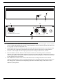
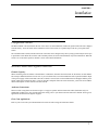
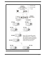
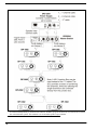
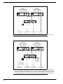
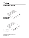
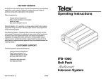
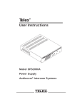
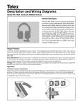
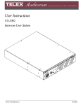
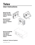
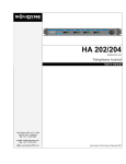
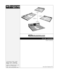
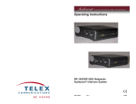
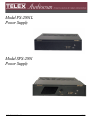
Model PS-2001L
Power Supply
Model SPS-2001
Power Supply
9350-7699-000 Rev E
9/2009
PROPRIETARY NOTICE
The product information and design disclosed herein were originated by and are
the property of Bosch Security Systems, Inc. Bosch reserves all patent, proprietary design, manufacturing, reproduction, use and sales rights thereto, and to any
article disclosed therein, except to the extent rights are expressly granted to others.
COPYRIGHT NOTICE
Copyright 2009 by Bosch Security Systems, Inc. All rights reserved. Reproduction, in whole or in part, without prior written permission from Bosch is prohibited.
WARRANTY NOTICE
See the enclosed warranty card for further details.
SHIPPING TO THE MANUFACTURER
All shipments of product should be made via UPS Ground, prepaid (you may
request from Factory Service a different shipment method). Any shipment
upgrades will be paid by the customer. The equipment should be shipped in the
original packing carton. If the original carton is not available, use any suitable
container that is rigid and of adequate size. If a substitute container is used, the
equipment should be wrapped in paper and surrounded with at least four (4)
inches of excelsior or similar shock-absorbing material. All shipments must be
sent to the following address and must include the Proof of Purchase for warranty
repair. Upon completion of any repair the equipment will be returned via United
Parcel Service or specified shipper, collect.
Factory Service Department
Bosch Security Systems, Inc.
8601 East Cornhusker Hwy.
Lincoln, NE 68507 U.S.A.
Attn: Service
CUSTOMER SUPPORT
Technical questions should be directed to:
Customer Service Department
Bosch Security Systems, Inc.
12000 Portland Avenue South
Burnsville, MN 55337 USA
Telephone: 1-877-863-4169
Fax: 800-323-0498
Factory Service: 800-553-5992 (Lincoln, NE)
This package should include the following:
PS-2001L
Qty.
Description
RETURN SHIPPING INSTRUCTIONS
Customer Service Department
Bosch Security Systems, Inc. (Lincoln, NE)
Telephone: 402-467-5321
Fax: 402-467-3279
Factory Service: 800-553-5992
1
PS-2001L Final Assembly
Please include a note in the box which supplies the company name, address,
phone number, a person to contact regarding the repair, the type and quantity of
Part No.
9010769-000 (US)
or
90107699001 (EU)
equipment, a description of the problem and the serial number(s).
1
User Manual
9350-7699-000
1
Warranty Statement
38110-390
4
Rubber Feet
56471-001
1
Power Cord, Black
2504-0003-00
1
Int’l Cordsets, if applicable
550024000
1
Statement of Conformity
38109-675
SPS-2001
9010-7699-000 (US)
1
SPS-2001 Final Assembly
or
1
User Manual
9350-7699-000
1
Warranty Statement
38110-390
4
Rubber Feet
56471-001
1
Power Cord, Black
2504-0003-00
1
Int’l Cordsets, if applicable
550024000
1
Patch Cord
50628-003
1
Statement of Conformity
38109-675
90107699-001 (EU)
THE LIGHTNING
FLASH AND
ARROWHEAD
WITHIN THE
TRIANGLE IS A
WARNING SIGN
ALERTING YOU OF
“DANGEROUS
VOLTAGE” INSIDE
THE PRODUCT.
CAUTION: TO REDUCE THE
RISK OF ELECTRIC SHOCK,
DO NOT REMOVE COVER.
NO USER-SERVICABLE
PARTS INSIDE. REFER
SERVICING TO QUALIFIED
SERVICE PERSONNEL.
THE
EXCLAMATION
POINT WITHIN
THE TRIANGLE IS
A WARNING SIGN
ALERTING YOU
OF IMPORTANT
INSTRUCTIONS
ACCOMPANYING
THE PRODUCT
SEE MARKING ON BOTTOM/BACK OF PRODUCT
WARNING: APPARATUS SHALL NOT BE EXPOSED TO DRIPPING OR
SPLASHING AND NO OBJECTS FILLED WITH LIQUIDS, SUCH AS VASES,
SHALL BE PLACED ON THE APPARATUS.
WARNING: THE MAIN POWER PLUG MUST REMAIN READILY OPERABLE
CAUTION: TO REDUCE THE RISK OF ELECTRIC SHOCK, GROUNDING OF
THE CENTER PIN OF THIS PLUG MUST BE MAINTAINED.
WARNING: TO REDUCE THE RISK OF FIRE OR ELECTRIC SHOCK, DO NOT
EXPOSE THIS APPRATUS TO RAIN OR MOISTURE.
WARNING: TO PREVENT INJURY, THIS APPARATUS MUST BE SECURELY
ATTACHED TO THE FLOOR/WALL/RACK IN ACCORDANCE WITH THE
INSTALLATION INSTRUCTIONS.
This product is AC only.
FCC STATEMENT
This equipment uses, and can radiate radio frequency energy that may cause interference to radio communications if not installed in accordance with this manual.
The equipment has been tested and found to comply with the limits of a Class A
computing device pursuant to Subpart J, Part 15 of FCC Rules which are designed
to provide reasonable protection against such interference when operated in a commercial environment. Operation of this equipment in a residential area may cause
interference which the user (at his own expense) will be required to correct.
Important Safety Instructions
1. Read these instructions.
2. Keep these instructions.
3. Heed all warnings.
4. Follow all instructions.
5. Do not use this apparatus near water.
6. Clean only with dry cloth.
7. Do not block any ventilation openings. Install in accordance with the
manufacturer’s instructions.
8. Do not install near any heat sources such as radiators, heat registers, stoves, or
other apparatus (including amplifiers) that produce heat.
9. Do not defeat the safety purpose of the polarized or grounding-type plug. A
polarized plug has two blades with one wider than the other. A grounding type
plug has two blades and a third grounding prong. The wide blade or the third
prong are provided for your safety. If the provided plug does not fit into your
outlet, consult an electrician for replacement of the obsolete outlet.
10.Protect the power cord from being walked on or pinched particularly at plugs,
convenience receptacles, and the point where they exit from the apparatus.
11.Only use attachments/accessories specified by the manufacturer.
12.Use only with the cart, stand, tripod, bracket, or table specified by the
manufacturer, or sold with the apparatus. When a cart is used, use caution when
moving the cart/apparatus combination to avoid injury from tip-over.
13.Unplug this apparatus during lightning storms or when unused for long periods
of time.
14.Refer all servicing to qualified service personnel. Servicing is required when the
apparatus has been damaged in any way, such as power-supply cord or plug is
damaged, liquid has been spilled or objects have fallen into the apparatus, the
apparatus has been exposed to rain or moisture, does not operate normally, or
has been dropped.
Table
of
Contents
IMPORTANT SAFETY INSTRUCTIONS ..........................................................................................................................................III
INTRODUCTION ........................................................................................................................................ 3
Description ................................................................................................................................................................3
INSTALLATION .......................................................................................................................................... 7
Configuration Switches .............................................................................................................................................7
Intercom Channel and Program Connections ...........................................................................................................7
CHANNEL CAPACITY: ................................................................................................................................................................7
AUDIOCOM CONNECTIONS: ......................................................................................................................................................7
CLEAR-COM APPLICATIONS: .....................................................................................................................................................7
Desktop or Rackmount Installation ...........................................................................................................................8
Power-Up Check .....................................................................................................................................................13
Specifications ...........................................................................................................................................................13
CHAPTER 1
Introduction
Description
The PS-2001L and SPS-2001 are versatile power supplies that can be used in a variety of Audiocom intercom system
applications. They both directly accept any AC input power from 100 to 240 VAC, 50/60 Hz and can be configured to power
two separate intercom channels or one large intercom channel with twice the intercom station capacity. Additionally, the units
can be configured for compatibility with Clear-Com Intercom Systems. The units may be rack mounted or used on a desktop.
For rack mounting, optional hardware is required. For desktop use, four non-marring rubber feet are supplied. The SPS-2001
also provides a speaker with two mixed inputs making it ideal for situations calling for a master station with a microphone/
speaker combination.
3
PS-2001L
®
1
Combine
Isolate
2
1
3
4
CH 1
100-240 VAC 60/50 HZ
TELEX COMMUNICATIONS, INC. MADE IN USA
2
CH 2
UNBAL
BAL
CLASS 2 WIRING 1.5A 24VDC
5
FIGURE 1.
4
PS-2001L Front and Rear Panel Features
1.
Combine/Isolate Switch: When in the Combine position, the unit will combine the audio signals of the two channels
to create a single audio channel where all users can intercommunicate. When in the Isolate position, the unit will create two groups of completely independent users.
2.
Channel Status Indicators: The indicators are green for normal operation and red when there is an overload or short
circuit. The circuitry in the unit will automatically reset when the overload or short circuit is located and fixed.
3.
Universal AC Power Input: The unit accepts any input power in the range of 100-240 VAC, 50/60 Hz.
4.
Intercom Channel Connectors: When the Combine/Isolate switch is set to the Isolate position, each channel
connector is powered separately and has completely separate intercom audio. When the Combine/Isolate switch is set
to the Combine position, each channel is still powered separately, but the audio signals are combined so that all users
on both channels can intercommunicate.
5.
BAL/UNBAL Selector Switch: This selector switch allows the user to configure the unit for use in either an
Audicom® (BALANCED) or Clear-Com (UNBALANCED) system. Compatibility includes channel connector pinouts, channel power requirements, and call signaling requirements. The default setting for this switch is in the
Audiocom® (BAL) position.
SPS-2001
®
1
Combine
Isolate
2
Volume
1
3
2
4
5
CH 1
INPUT 1
CH 2
SPEAKERS
LINE LEVEL
1VRMS
100-240 VAC 60/50 HZ
TELEX COMMUNICATIONS, INC. MADE IN USA
INPUT 2
UNBAL
BAL
CLASS 2 WIRING 1.5A 24VDC
6
FIGURE 2.
SPS-2001 Front and Rear Panel Features
1.
Speaker, Inputs, and Volume Control: Two audio inputs are provided. The inputs are combined internally and set as a
monaural signal to the internal speaker amplifier. The Volume control adjusts the level to the front panel speaker.
Typically, these inputs are used with the speaker outputs of a master station when the master station is set for use with
a panel microphone and speaker instead of a headset.
2.
Combine/Isolate Switch: When in the Combine position, the unit will combine the audio signals of the two channels
to create a single audio channel where all users can intercommunicate. When in the Isolate position, the unit will
create two groups of completely independent users.
3.
Channel Status Indicators: The indicators are green for normal operation and red when there is an overload or short
circuit. The circuitry in the unit will automatically reset when the overload or short circuit is located and fixed.
4.
Universal AC Power Input: The unit accepts any input power in the range of 100-240 VAC, 50/60 Hz.
5.
Intercom Channel Connectors: When the Combine/Isolate switch is set to the Isolate position, each channel connector
is powered separately and has completely separate intercom audio. When the Combine/Isolate switch is set to the
Combine position, each channel is still powered separately, but the audio signals are combined so that all users on
both channels can intercommunicate.
6.
BAL/UNBAL Selector Switch: This selector switch allows the user to configure the unit for use in either an
Audiocom® (BALANCED) or Clear-Com (UNBALANCED) system. Compatibility includes channel connector pinouts, channel power requirements, and call signaling requirements. The default setting for this switch is in the
Audiocom® (BAL) position.
5
6
CHAPTER 2
Installation
Configuration Switches
The BAL/UNBAL switch (located on the rear of the unit) is set to the Balanced (Audiocom) position when the unit is shipped
from the factory. To set the switch to the Unbalanced (Clear-Com) mode, use a pointed object such as a pen to push in the
switch.
The Combine/Isolate switch (located on the front of the unit) can be changed at any time by using a pointed object such as pen
to push in the switch. When the switch is in the Combine position, all users on both channels may intercommunicate. When the
switch is set to the Isolate position, channels 1 and 2 cannot intercommunicate.
Intercom Channel and Program Connections
Channel Capacity:
When connecting intercom stations to the PS-2001L or SPS-2001, determine the total current for all stations on each channel.
The total per channel should not exceed 1.0A. If you exceed this limit, an overload indication will be provided and the output
of the power supply will be turned OFF. Once the overload is corrected, the overload indications will disappear and the power
supply output will be turned ON. Note, if you are using DC wallpacks with some intercom stations, you do not need to add the
current consumption of those station to the total current.
Audiocom Connections:
Intercom cable wiring details are shown in Figure 3 on page 8. Speaker and interconnection cables (SPS-2001 Only) are
standard RCA phono types. For program input cable wiring, refer to your master intercom station user manual. Some typical
applications are shown in the figures on page 9.
Clear-Com Applications:
Refer to your Clear-Com system documentation for intercom cable wiring and connection details.
7
Desktop or Rackmount Installation
For desktop use, install the four supplied rubber feet to the bottom of the unit. Do not obstruct the cooling vents when using
the unit on a desktop. For rack mounting, use an optional Audiocom Rackmount Kit. Several kits are available to meet the
requirements of your particular system. Follow the assembly instructions supplied with the rack mount kit.
TYPICAL 1-CHANNEL CABLE WIRING
3
2
Pair 1
3
2
1
Pair 2
1 (Both wires)
Shield
Shield
Cable Type: 22AWG Stranded, 2-Pair Twisted-wire, with Shield
Connector Type: 3-Pin XLR Audio (Neutrik or Switchcraft)*
Pin 1: Common
Denotes twisted pair.
Pin 2: Channel Audio / Power
Pin 3: Channel Audio / Power
Denotes shield.
Shield: Earth ground
TYPICAL 2-CHANNEL CABLE WIRING
4
3
6
5
4
3
6
5
Pair 1
Pair 2
1
1 (Both wires)
Pair 3
Shield
Shield
Cable Type: 22AWG Stranded, 3-Pair Twisted-wire, with Shield
Connector Type: 6-Pin XLR Audio (Neutrik only, not compatible with 6-pin Switchcraft)*
Pin 1: Channel 1 & 2 Common
Pin 2: No connection
Denotes twisted pair.
Pin 3: Channel 1 Audio / Power
Pin 4: Channel 1 Audio / Power
Denotes shield.
Pin 5: Channel 2 Audio / Power
Pin 6: Channel 2 Audio / Power
Shield: Earth ground
3
Ch1 2
1
Case
“Y” CABLE WIRING
Pair 1
Pair 2
3
Ch2 2
1
Shield
Pair 3
4
3
6
5
1 (Both wires)
Shield
Use second drain wire if available, or add an extra section of wire.
*
FIGURE 3.
8
Standard cables are generally constructed using a male connector at one end and a
female connector at the other end. This allows several cables to be interconnected to
create longer cable runs. Audiocom master stations, speaker stations and belt packs
also typically provide both a male and female Neutrik connector for each intercom
channel. This permits loop-through connection of several intercom stations using the
standard cables. Audiocom power supplies use a 3-pin male Neutrik connector for
each channel. Audiocom wallplates use male Neutrik connectors.
Cable Wiring Diagrams for Audiocom Applications
FIGURE 4.
Typical connections using a single PS-2001L Power Supply to power two channels.
9
Typical connections using on SPS-2001 Power Supply for two intercom channels. The two program sources
are monitored independently by their intercom channels. All audio (program and intercom) is monitored as a monaural
mix in the SPS-2001 speaker. The US2000A is set for monaural speaker output (default).
FIGURE 5.
10
The two program sources are monitored independently by the intercom channels. The SPS-2001 monitors
intercom channel 1 and program 1. The SPK-1000 monitors intercom channel 2 and program 2. The US2000A is sent
for binaural speaker output as described in the US2000A User Manual.
FIGURE 6.
11
PS-2001L
Channel 1 Power
Combine / Isolate Switch
set to Combine
PS-2001L
Channel 2 Power
Combine / Isolate Switch
set to Combine
CH 2
CH 1
CH 2
CH 1
100-240 VAC 60/50 HZ
100-240 VAC 60/50 HZ
TELEX COMMUNICATIONS, INC.
MADE IN USA
TELEX COMMUNICATIONS, INC.
BAL
UNBAL
MADE IN USA
BAL
UNBAL
CLASS 2 WIRING 1.5A 24VDC
CLASS 2 WIRING 1.5A 24VDC
1
1
PUSH
PUSH
PROGRAM
INPUTS
+
1
SPEAKERS
LINE LEVEL
1 VRMS
-
VOL
PGM 1
VOL
PGM 2
2
P.A.
12-15 VDC
EXP
OUT
BAL - OUT
UNBAL - IN
CHN 2
CHN 1
PS-L
(Optional)
1
1
To ½ of stations
on channel 1
1
To ½ of stations
on channel 1
1
To ½ of stations
on channel 2
To ½ of stations
on channel 2
Using two PS-2001L Power Supplies to provide a greater capacity on each channel.
FIGURE 7.
SPS-2001
Channel 1 Power
Combine / Isolate Switch
set to Combine
SPS-2001
Channel 2 Power
Combine / Isolate Switch
set to Combine
CH 2
CH 1
SPEAKER
INPUT 1
INPUT 1
INPUT 2
100-240 VAC 60/50 HZ
TELEX COMMUNICATIONS, INC.
MADE IN USA
LINE LEVEL
1 VRMS
CH 2
CH 1
SPEAKER
INPUT 2
100-240 VAC 60/50 HZ
TELEX COMMUNICATIONS, INC.
BAL
UNBAL
MADE IN USA
LINE LEVEL
1 VRMS
CLASS 2 WIRING 1.5A 24VDC
BAL
UNBAL
CLASS 2 WIRING 1.5A 24VDC
1
4
4
1
PUSH
PUSH
PROGRAM
INPUTS
+
SPEAKERS
LINE LEVEL
1 VRMS
-
1
VOL
PGM 1
VOL
PGM 2
2
P.A.
12-15 VDC
EXP
OUT
BAL - OUT
UNBAL - IN
CHN 2
CHN 1
US2000A
Internal DIP
switches set
for binaural
operation
PS-L
(Optional)
1
Program input
cable. From 2
audio sources
To ½ of stations
on channel 1
1
To ½ of stations
on channel 1
1
To ½ of stations
on channel 2
1
To ½ of stations
on channel 2
Using two SPS-2001 Power Supplies to provide a greater capacity on each channel.
Using two SPS-2001 Power Supplies also lets you independently monitor and adjust volume for
both intercom channels without the need for a separate powered loudspeaker. In this application,
the US-2000A should be set for binaural speaker output as described in the US2000A manual.
FIGURE 8.
12
Power-Up Check
1.
Plug in any DC wallpacks that are being using with
individual intercom stations.
Specifications
General
Input Power Requirements
100 to 240 VAC, 50/60 Hz
NOTE: If you plug in DC wallpacks after applying power to
the PS2001L or SPS-2001, you may get an overload
indication. This is because the stations that are being
powered by wallpacks will draw current from the units until
their own DC wallpack supplies are connected. To correct
the problem, plug in the DC wallpacks.
Current Draw
750mA maximum (SPS-2001)
700mA maximum (PS-2001L)
Output Power (each channel)
24 ±1 VDC, 1 Amp per channel
Dimensions
2.
3.
Plug in the AC power cords for any connected PS2001L or SPS-2001 Power Supplies. The channel
status indicators should be green.
If a channel status indicator turns red during
operation, locate the short or overload that is
causing the problem. Once the short or overload is
corrected, the Power Supply should reset itself and
the overload indication should go away.
1.75” (44.5 mm) high x 8.25” (209.5mm) wide x 10.31” (261.9mm) deep
Weight
approximately 2.5 lb. (1.13 kg.)
Environmental Requirements
Storage:
-20° C to 80° C, 0% to 95% humidity, non-condensing
Operating:
0° C to 50° C, 0% to 95% humidity, non-condensing
Intercom Channels (General)
Connector Type:
One XLR-3M audio connector for each channel. Pin-out depends on setting
of BAL/UNBAL switch for balanced or unbalanced operation as defined
below:
Balanced Mode (set to BAL position)
Line Terminating Impedance: 300 ohms ±10%
Connector Pinout
Pin 1
Common (audio and DC return)
Pin 2
Full-duplex, balanced intercom audio and +24 VDC output
Pin 3
Full-duplex, balanced intercom audio and +24 VDC output
Unbalanced Mode (set to UNBAL position)
Line Terminating Impedance: 200 ohms ±10%
Connector Pin-out:
Pin 1
Common (audio and DC return)
Pin 2
+30VDC ±1VDC
Pin 3
Full-duplex, unbalanced intercom audio high
Speaker Inputs (SPS-2001 only)
Type:
RCA Phone Jack
Tip:
Speaker + Input
Sleeve:
Speaker - Input
Approvals
UL, CUL, CE
13