1
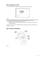
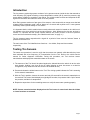
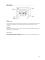
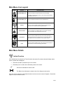
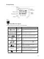
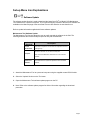
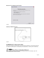
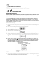
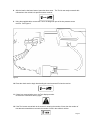
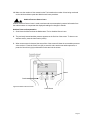
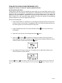
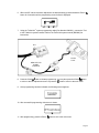
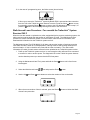
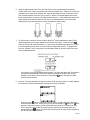
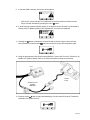
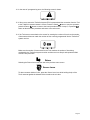
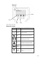
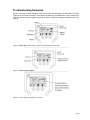
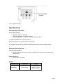
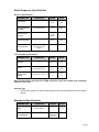
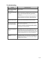
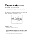
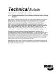
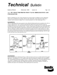
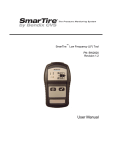
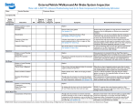
® SmarTire® TPMS Maintenance Hand Tool Revision 1.04 User Manual Page 2 Table of Contents FCC Compliance Label .................................................................................................................4 User Interface Illustration .............................................................................................................4 Introduction ...................................................................................................................................5 Testing Tire Sensors ....................................................................................................................5 Main Menu......................................................................................................................................6 Main Menu Icon Legend ...............................................................................................................7 Main Menu Details .........................................................................................................................7 Initiate Function ........................................................................................................................................7 Example Display ......................................................................................................................................8 Set-up Menu Icon Explanations...................................................................................................9 Maintenance Tool Software Update .....................................................................................................9 Maintenance Tool software update program ......................................................................................10 Updating Maintenance Tool ...............................................................................................................10 psi/BAR/kPa/C/F - Measurement Units ..................................................................................................10 Walk-Around Learn ................................................................................................................................11 Walk-Around Learn Procedure ...........................................................................................................11 Ambient Pressure Sensor Learn ............................................................................................................13 Ambient Pressure Compensation ......................................................................................................13 TRAILER CIP .........................................................................................................................................14 Walk-Around Learn Procedure – For use with the TrailerLink™ System Receiver ONLY.......................16 Sensor Learn .........................................................................................................................................19 Execution Icons...........................................................................................................................20 Troubleshooting Examples ........................................................................................................21 Specifications ..............................................................................................................................22 Hardware Specifications ........................................................................................................................22 General Specifications .......................................................................................................................22 Electrical Specifications .........................................................................................................................22 Communication Interfaces .................................................................................................................22 System Resources .............................................................................................................................22 Power .....................................................................................................................................................22 Radio Frequency Specifications .............................................................................................................23 Receiver Specifications ......................................................................................................................23 LF Transmitter Specifications .............................................................................................................23 Antenna Type .....................................................................................................................................23 Mechanical Specifications ......................................................................................................................23 Troubleshooting ..........................................................................................................................24 Page 3 FCC Compliance Label The FCC compliance label is located on the back of the Tool as shown in Figure 1. Figure 1 This device complies with part 15 of the U.S. Federal Communications Commission (FCC) Rules and with RSS-210 of Industry Canada. Operation is subject to the following two conditions: (1) this device may not cause harmful interference, and (2) this device must accept any interference received, including interference that may cause undesired operation. The term "IC:" before the radio certification number only signifies that Industry Canada technical specifications were met. User Interface Illustration Figure 2 Page 4 Introduction The tire pressure monitoring system consists of a tire pressure sensor inside the tire that transmits a radio frequency (RF) signal containing a unique identification number (ID #), actual tire pressure, and sensor battery condition to a module in the vehicle. The vehicle module receives and interprets the RF signal from the sensor and warns the driver of low tire pressure. Note: Early systems used one of two types of tire sensors: a tire sensor with an orange cover that had a battery-saving “stationary mode”; and an “always on” tire sensor with a yellow cover. Later systems exclusively use the yellow “always on” tire sensor. It is important that the vehicle module knows exactly where each sensor is located on the vehicle so it can indicate to the driver which tire has incorrect pressure. Note: Whenever the tires are serviced or rotated, it is important that the vehicle module relearns the current position of each tire pressure sensor and tire and wheel assembly. (See "Walk-Around Learn" on page 11.) The tire pressure sensor responds with a signal for a period of time once the "activate" button is pressed on the hand Tool. The main menu of the Tool identifies three functions — the Initiate, Setup and Learn modes respectively. Testing Tire Sensors The sensor test procedure is used to verify that the sensors can transmit valid data after they have been activated with a low frequency (LF) transmission from the Tool. Refer to the vehicle service manual for further diagnostic information. During this procedure, the Tool receives sensor transmissions and displays the transmission data on the screen. 1. The antenna of the Tool should be placed against the sidewall above the wheel rim at the valve stem location. Holding it too close to the rim (while initiating an inner tire sensor on a dual tire configuration, may cause the outer tire sensor to be initiated as well). 2. Press and release the Initiate button on the Tool. The circling symbol indicates the Tool is scanning for the sensor's transmission. 3. With the Tool in position, observe the screen and wait 3-5 seconds for the sensor's transmission to be received. The screen should display an eight-digit ID number, tire pressure within 2 psi of actual tire pressure, and the tire’s temperature. 4. Repeat the steps above for the remaining sensors to verify all sensors are operating properly. NOTE: Sensor transmission data displayed on the Tool screen is erased each time the Initiate or Learn functions are selected. Page 5 Main Menu Figure 3 Initiate Function If the Initiate button is pressed, the Tool retrieves the sensor ID, pressure data and battery status from the sensor which is displayed. Review the Application section of this guide (page 21) for more information. Setup Menu If the Setup button is pressed, the Tool enters the Setup mode. Review the Application section of this guide (page 21) for more information. Learn Function If the Learn button is pressed, the Tool learns/displays the sensor ID. Review the Application section of this guide (page 21) for more information. Page 6 Main Menu Icon Legend ICON STATE DESCRIPTION Handheld Battery Life These icons indicate the battery life of the handheld device at startup. This icon is located in the lower left area of the Tool display. To continue, press the Check mark. To turn off the Tool and replace the batteries, press the X. Handheld Battery Life This icon indicates the battery life of the handheld device. Initiation This icon is used to indicate initiation. When the Initiate button is selected, this icon starts to blink during transmission. Initiation Failure This icon indicates Tool initiation failure. This could be caused by either a low battery in the wheel sensor or the Tool. Set-up Menu This icon is used to indicate the set-up menu. When this button is selected and held for 2 seconds the set-up menu appears. Refer to Menu Options for more information to set-up specific options. Learn This icon is used to indicate sensor Learn. When the Learn button is selected this icon starts to blink during transmission. Main Menu Details Initiate Function If the Initiate button is pressed, the Tool will retrieve the sensor ID, pressure data and battery status from the sensor that is displayed The button should be pressed only once to activate. The battery icon is used to show the battery status of the sensor. Check icons indicates the sensor is OK. The Wrench icon indicates the sensor is due for a change at next service. If an error occurs, such as no information has been received, an error screen will appear. Should this happen, retry the Initiate Function. Page 7 Example Display Figure 4 Set-up Menu Icon Legend Selecting the Setup button commands the Tool into Setup mode. ICON psi/BAR/kPa/C/F STATE DESCRIPTION Software Update This icon indicates the software update option which allows the user to download the latest software from a personal computer. Measurement Units This option allows the user to change the units of the parameters displayed. See page 10. Stored Sensor Information Retrieval This option allows the user to refer to sensor information stored in memory. Up to 100 sensors can be stored. Delete Sensors in Memory This option allows the user to delete all sensors stored in memory. This option is used for the Walk-Around Learn process. Walk-Around Learn TRAILER CIP When Walk-Around Learn is initiated the icon may appear indicating a low battery in either the wheel sensor or the Tool. Ambient Sensor Learn This option is used to activate and store pressure information from the ambient sensor to adjust the displayed readings for changes in altitude. Program CIP Values This function is used to program the cold inflation pressures ™ in the TrailerLink system by Bendix CVS. Each axle can be programmed with a different Cold Inflation Pressure (CIP) value. Five (5) Axles are supported. Return This option allows the user to return to the main window. Page 8 Set-up Menu Icon Explanations Software Update The software update function is used to download the latest SmarTire® by Bendix CVS Maintenance Tool software from a personal computer. The current and legacy versions of the SmarTire software are available on the Manuals page of the www.SmarTire.com site and also on www.bendix.com. Refer to update information supplied with future software updates. Maintenance Tool Software Update The Maintenance Tool function allows the user to easily upgrade the software in the field. The following describes the items and steps required to carry out the download. Item Required Custom RS-232 Cable Description This cable is required to connect from the computer to the Tool (see Figure 6). ® ® Microsoft Windows 95, 98, 2000, XP Required Computer Update Tool Software Refer to the User Manual for instructions on how to use this software. The software that is required to update the Tool to the latest features. 1. Attach the Maintenance Tool to a personal computer using the supplied custom RS-232 cable. 2. Select the "update" function on the Tool menu. 3. Open the Maintenance Tool software update program on the PC. 4. Note: Refer to the software update program for further information regarding the download procedure. Page 9 Maintenance Tool Software Update Program Figure 5 Updating The Maintenance Tool Figure 6 psi/BAR/kPa/C/F - Measurement Units This function changes the measurement units of the parameters displayed: psi (pounds [pound-force] per square inch), BAR (equal to 100 kilopascals), kPa (kilopascals), C (Celcius), and F (Fahrenheit). Stored Sensor Information Retrieval This function allows the user to refer to sensor information stored in the Tool memory. Up to 100 sensor readings can be stored & retrieved. Page 10 Delete Sensors in Memory This function is used to delete all sensor data stored in the Tool memory. Walk-Around Learn Walk-Around Learn Procedure When the tires are rotated or replaced on a vehicle with a tire pressure monitoring system, the vehicle must re-learn the position of each tire. The Walk-Around Learn procedure is used to activate each sensor in its new location, store the sensor information, and download to the vehicle’s tire pressure sensor receiver. The unit will learn and store the location of each sensor as the user walks around the vehicle in a Ushaped pattern, starting at the left side (looking forward) front-most tire location. If this is a dual tire axle, start with the inner tire location. The new location information (tire IDs) for each sensor collected is then uploaded to the receiver in the vehicle. Perform the following steps: 1. Power up the vehicle’s tire pressure sensor receiver (see vehicle's service information for specific details). 2. Press and hold the Setup button until a list of menu items appear. 3. Select the Walk-Around Learn icon. 4. Select the number of tires on the vehicle. 5. Activate each of the vehicle's wheel sensors in the proper order (counter-clockwise and inner tire to outer tire, starting from the front left tire). See the "Walk-Around Learn" card included with the Tool. 6. Hold the SmarTire® system Tool’s antenna against the tire’s upper sidewall in line with the valve stem. Press the Learn button. The Tool is able to receive signals from an inner tire on a dual tire configuration as well. Just hold the Tool in line with the circumferential position of the valve stem of the inner wheel, as indicated in Figure 7. Figure 7 7. Once the Tool has learned the tire sensor ID for the given position, it automatically switches to the next tire position. Repeat until all the tires have been learned. Page 11 8. After the last tire has been learned, press the down arrow. The Tool is now ready to transmit this information to the vehicle’s tire pressure sensor receiver. 9. Using the supplied cable, connect the Tool to the diagnostic port of the tire pressure sensor receiver. See Figure 8. Figure 8 10. Press the check mark to begin downloading the new tire sensor IDs into the receiver. 11. If there is a communication error, the Tool displays an alert. Check all the connections and try again. 12. If the Tool screen reverts back to the screen for entering the number of tires, then the number of tires that was entered does not match the number of tires in the vehicle’s receiver. Page 12 13. Make sure the number of tires entered on the Tool matches the number of tires being monitored on the vehicle and then repeat the Walk-Around Learn procedure. Ambient Pressure Sensor Learn Ambient Pressure Sensor Learn is used to activate and store atmospheric pressure information from the ambient sensor to compensate the displayed readings for changes in altitude. Ambient Pressure Compensation 1. Scroll down the Menu and set the Maintenance Tool to Ambient Sensor Learn. 2. The previously learned ambient pressure appears on the first line of the screen. To learn a new ambient sensor, press the learn button (center). 3. When a new sensor is detected, the second line of the screen will show the new ambient pressure value received. Press the Check icon (left) to save this value as the new ambient pressure, or press the Cancel icon (right) to discard this value and exit the screen. Cancel Good Figure 9 Ambient Pressure Screen Learn Button Page 13 TRAILER COLD INFLATION PRESSURES (CIP) Program CIP of Axles in TrailerLink™ System by Bendix CVS ECU CIP Programming Procedure TPMS pressure warning levels are calculated as a percentage of a tire’s cold inflation pressure (CIP). The default levels are 15% below the CIP (temperature compensated) for the first alert level, and 20% below the CIP (non-temperature compensated) for the second warning level. The default CIP programmed into the TrailerLink™ system ECU is 100psi for all axles. Each axle can be configured to have a unique CIP. If the case arises where different CIP values are required, the programming procedure detailed on the next two pages should be used. Perform the following steps: 1. Power-up the TrailerLink™ system ECU. In most cases the trailer will need to be connected to a tractor in order to receive power. The diagnostic LED on the TrailerLink system harness can be viewed at power-up to ensure that the ECU has power. 2. Using the Maintenance Hand Tool, press and hold the Setup items appear. 3. Select the Trailer CIP menu item and press the Return button until a list of menu button. 4. Use the Up and Down arrow buttons to configure the system for the total number of axles installed on the trailer. A maximum of five (5) axles can be configured. When the correct number of axles is selected, press the Return button. 5. Next, adjust the CIP value for each axle. The default value of 100psi will be shown on the screen (if imperial units are selected). Use the Up and Down arrow buttons to adjust the value of the CIP. Holding down the arrow buttons will cause the values to increment at an increasing rate. Press the Return/Right button to advance to the next axle. Page 14 6. When the CIP values have been adjusted to the desired setting, press and hold the Return button for 3 seconds until the programming screen bellow is displayed. 7. Using the TrailerLink™ system programming cable (Part Number K092501), connect the Tool to the TrailerLink system harness. Refer to the TrailerLink system manual (BW2920) for instructions. ECU HAND TOOL REMOVE LED INSERT HARNESS 8. Press the Check button to initiate programming. You may also press the Return button to return to the CIP adjustment screen or press the button to return to the main menu. 9. Once programming has been initiated, the following screen appears. 10. After successful programming, this screen is shown. 11. After programming, press the Return button to exit to the main menu. Page 15 12. In the case of a programming error, the failure screen (shown below). If this occurs, ensure the TrailerLink™ system by Bendix ECU is powered and the connection from the Tool to the TrailerLink system harness is correct. Press the Check button to retry the operation; press the Return button to return to the CIP adjustment screen in step 5; or press the button to abort the programming and return to the main menu. Walk-Around Learn Procedure – For use with the TrailerLink™ System Receiver ONLY When the tires are rotated or replaced on a trailer equipped with a tire pressure monitoring system, the trailer receiver must be taught the new position of each sensor ID code. The Walk-Around Learn procedure is used to activate each sensor in its new location, store the sensor information, and download this information into the TrailerLink system receiver. The Maintenance Hand Tool (P/N 090.0011) will learn and store the location of each sensor as the user walks around the trailer in a U-Shaped pattern, starting at the left side (looking forward) frontmost tire location. If this is a dual-tire axle, start with the inner tire location. The new location information (ID codes) for each sensor collected is then uploaded to the TrailerLink system receiver. 1. Power up the TrailerLink system receiver. In most cases the trailer will need to be connected to a tractor in order to receive power. The diagnostic LED on the TrailerLink system harness can be viewed at power up to ensure that the ECU has power. 2. Using the Maintenance Hand Tool, press and hold the Setup items appear. 3. Select the Walk-Around Learn 4. Use the Up and Down icon and press the Return button until a list of menu button. arrow buttons to select the number of tires on the trailer. 5. When the correct number of tires is selected, press the Return Around Learn procedure. button to initiate the Walk- Page 16 6. Using the Maintenance Hand Tool, go to the first tire to be programmed and proceed to activate each of the trailer’s tire pressure sensors in the proper order. Starting on the left side (road side) of the trailer at the forward axle, begin by activating the inner tire and proceed to work counterclockwise from inner to the outer tire. Work in a U-shaped pattern around the trailer ending with the right side (curb side) forward outer tire. If using wide-based single tires, simply start at the forward left side tire and work in a U-Shaped pattern around the trailer ending with the right side forward tire. Some examples are shown below: 7. To activate the tire pressure sensor, hold the SmarTire® system Maintenance Hand Tool’s antenna against the tire’s upper sidewall in-line with the valve stem. Press the Learn button to learn the ID code of the sensor. In most cases, the Maintenance Hand Tool is able to receive signals from the inner tire on the dual tire configuration as well. To program the inner tire, hold the Tool in line with the circumferential position of the valve stem of the inner wheel, as indicated below: If the sensor is not programmed from this position, you many also place the Tool between the dual tire assemblies and activate the sensor by placing the antenna near the tire sidewall, in-line with the inner valve stem. Pressing the button will abort the WalkAround Learn procedure. 8. Once the Tool has learned the tire pressure sensor ID for the given position, it briefly displays the received ID code and automatically switches to the next tire position. Press the Learn button to initiate the next tire sensor. Repeat until all the tires have been learned into the Tool. At this point you may also press the Up and Down arrow buttons to select and view any previously learned wheel positions. If needed, you may also re-program a tire position by simply selecting a previously learned position and pressing the Learn button. Any previously learned sensor ID codes will be replaced by the new ID code for that position. Page 17 9. If a sensor failed to activate, this screen will be appear: If this occurs, ensure that the Tool is placed at the correct position around the tire and retry the sensor activation by pressing the Learn button. 10. If, while learning a particular wheel position, a tire pressure sensor ID code is received that is already used in a different position, this "Duplicate ID" error screen is displayed: 11. Pressing the button will delete the received ID and the screen will go to the previously learned position. Press the Learn button to learn the tire sensor into the position again. 12. Using the programming cable (Part Number K092501), connect the Tool to the TrailerLink™ by Bendix CVS system harness. Refer to the TrailerLink system manual for instructions. ECU HAND TOOL REMOVE LED INSERT HARNESS 13. Press the Check button to begin downloading the new tire sensor IDs into the TrailerLink™ by Bendix CVS system receiver. Page 18 14. In the case of a programming error, the following screen is shown. 15. If this occurs, ensure the TrailerLink system ECU is powered and the connection from the Tool to the TrailerLink system harness is correct. Press the Check button to retry the operation; press the Return button to return to the learn procedure screen in step 5; or press the button to abort the learn procedure and return to the main menu. 16. If the Tool screen reverts back to the screen for entering the number of tires, then the number of tires entered does not match the number of tires currently programmed into the TrailerLink™ system receiver. Make sure the number of tires entered on the Tool matches the number of tires being monitored by the TrailerLink system receiver and then return to Step 4 and repeat the WalkAround Learn procedure. Return Selecting the Return icon moves the user to the previous menu screen. Sensor Learn To detect a sensor inside of a tire, press the Sensor Learn icon while holding the tip of the Tool’s antenna against the sidewall of the tire above the air valve. Page 19 Battery Initiate Set Up Figure 10 Sensor Learn Screen Execution Icons ICON STATE DESCRIPTION Confirm Good X Cancel Cancels current action. Back Back, Select, Enter, Return to main menu. Scroll Scroll displayed data or selection. Sensor information was not received. Alert If in Walk-Around Learn mode, the sensor ID has already been designated to a tire location. Sensor Maintenance The battery of the tire pressure sensor may be low. Data Not Received Battery information not received by the Tool. Try again. Page 20 Troubleshooting Examples Figures 11 through 14 show examples of potential screens after activating a sensor (within LF sensor range) using the Initiate command. The received information by the Maintenance Tool is stored in the Tool memory and can be recalled by selecting the Sensor Information Storage command in the menu settings. Figure 11 Sensor OK: Sensor name, tire pressure & temperature, battery OK Figure 12 Sensor with low battery Figure 13 Sensor battery information not received Page 21 Figure 14 Sensor not found Specifications Hardware Specifications General Specifications Handheld 125 kHz LF generator. (To provide activation of SmarTire® sensors) Requires replaceable “C” cell batteries (either Alkaline or NiMH) The battery compartment is in the rear of the unit. Battery life expectancy is approximately 300+ activations. A Tool battery level indicator is located in the lower left hand corner of the main display screen. Electrical Specifications Communication Interfaces RS-232 (diagnostic interface port): Used for updating the Tool and for communicating with J1939 receiver. System Resources 100 sensor memory space. Power PARAMETERS Supply Voltage CONDITION VALUE (Alkaline or NiMH) Three (3) “C” Cell Batteries, or equivalent NiMH rechargeable. Page 22 Radio Frequency Specifications Receiver Specifications PARAMETERS CONDITION VALUE UNITS - 433.92 MHz Direct Measurement -95 dBm - OOK (On-Off Keying) - 400 KHz CONDITION VALUE UNITS - 118 to 130 KHz To SmarTire sensor 22 ± 1 Inches Distance of 7 inches 1.5 ± 0.1 1.9 mA/m nT RF Frequency Receiver Sensitivity (2E-3 BER) Modulation Type (Receiver) Receiver Bandwidth Receiver Distance Compatible with LF transmitter operation distance LF Transmitter Specifications PARAMETERS Frequency Distance Magnetic Field Strength ® Note: Communication with a SmarTire TPMS system tire sensor will operate up to a maximum distance of 22 inches. Antenna Type The SmarTire system Tool has an internal antenna for communicating with SmarTire system sensors. Mechanical Specifications PARAMETERS Weight Housing Material CONDITION VALUE UNITS Without batteries 2 Lbs - Injection molded plastic enclosure Page 23 Troubleshooting Problem Potential Solution The Tool does not power up or turns off when the Initiate button is pressed. Replace batteries. No tire pressure sensor data is received. Make sure the antenna is held within 22 inches of the tire pressure sensor in position before the Initiate button is momentarily selected. The Tool should be held in that position for at least 3.5 to 5 seconds. If still unsuccessful, try to activate and receive tire pressure sensor data from another tire pressure sensor. If the other sensor is received successfully, you may need to replace the first sensor. Setup menu button does not work. Be sure to press and hold the button for at least 2 seconds. The Tool does not receive a sensor transmission after a sensor has been activated. Make sure the Tool's antenna is held within 22 inches of the sensor when activating a sensor. Wrong sensor initiated (dual tire only). When initiating a sensor in a dual tire configuration the ID codes received are the same for both the inner and outer tires. The antenna of the Tool should be moved within 22 inches of the target tire pressure sensor (the antenna should be held against the outer tire when activating the inner tire on a dual tire configuration). LCD Backlight is off during operation. If the Battery Indicator on the bottom left corner of the display is showing that the battery level is low (the icon mostly empty), the backlight will automatically turn off to conserve power. Replace the batteries when convenient. This process may need to be repeated up to 3 times. If a sensor continues to not respond, refer to the vehicle service manual for further diagnostic or repair information. Page 24 Duplication of this document in whole or in part for any purposes other than those for which it was originally intended, without the written approval of Bendix Commercial Vehicle Systems LLC is strictly prohibited. The information provided in this manual is for informational purposes only and is subject to change without notice and should not be construed as a commitment by Bendix. Bendix assumes no responsibility or liability for any errors or inaccuracies that may appear in this publication. Trademarks ® ™ The SMARTIRE and TRAILERLINK trademarks are owned by Bendix Commercial Vehicle Systems LLC. Any references in this catalog to MICROSOFT, WINDOWS and any other company or trademark are solely for identification purposes. The trademarks are the property of their respective companies and are not affiliated with or endorsing Bendix Commercial Vehicle Systems LLC. Bendix Commercial Vehicle Systems LLC does not represent any parts shown as products manufactured or remanufactured by the companies so named herein. ® 901 Cleveland Street • Elyria, Ohio 44035 • www.bendix.com • 1-800-AIR-BRAKE (1-800-247-2725) BW2809 ©2013 Bendix Commercial Vehicle Systems LLC, a member of the Knorr-Bremse Group • 2/13 • All Rights Reserved Page 25