1
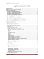
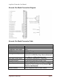
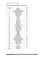
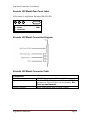
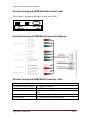
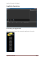
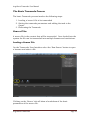
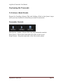
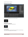
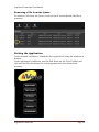
ArgoNavis Transcoder User Manual
ArgoNavis
Transcoder
Installation
and
User Guide
Version 10.0.5.x
ArgoNavis Transcoder
Page 1
ArgoNavis Transcoder User Manual
ArgoNavis Encoder User Guide
Introduction .................................................................................................................... 3
Special Notes on the Touch Screen ......................................................................... 3
Physical Connections ................................................................................................... 3
Encoder Pro Model Rear Panel label .............................................................................. 3
Encoder Pro Model Connection Diagram ....................................................................... 4
Encoder Pro Model Connector Table ............................................................................. 4
Encoder Pro Model Breakout Cable Pinout. ................................................................... 5
Encoder SDI Model Rear Panel Label ............................................................................ 6
Encoder SDI Model Connection Diagram ...................................................................... 6
Encoder SDI Model Connector Table............................................................................. 6
Encoder Analog and HDMI Model Rear Panel Label .................................................... 7
Encoder Analog and HDMI Model Connection Diagram .............................................. 7
Encoder Analog and HDMI Model Connector Table ..................................................... 7
System Specifications .................................................................................................. 8
ArgoNavis Operations .................................................................................................. 9
Launching the Application ..................................................................................... 9
The Basic Transcode Process .............................................................................. 10
Source Files............................................................................................................... 10
Loading a Source File ........................................................................................ 10
Adding a New Task to the Queue....................................................................... 11
Setting Transcoder Parameter Values .......................................................... 11
Format .................................................................................................................... 12
Mux .......................................................................................................................... 12
Mux Rate (kbps)................................................................................................... 12
Video ........................................................................................................................ 13
Audio ....................................................................................................................... 13
Audio Bitrate......................................................................................................... 13
GOP Parameters for MPEG-2 .......................................................................... 13
GOP Parameters for H.264 .............................................................................. 14
GOP Parameters for Windows Media Format ............................................ 14
Scaling the Video Output ................................................................................. 15
Cropping the Video Output.............................................................................. 15
Filename and Path .............................................................................................. 15
Templates............................................................................................................... 15
Add Task to Queue ............................................................................................. 15
Performing the Transcode .................................................................................... 16
To Perform a Batch Encode ............................................................................. 16
Transcoder Controls ........................................................................................... 16
Starting the Transcoder .................................................................................... 17
Stopping the Transcoder .................................................................................. 17
Current Queue ..................................................................................................... 17
Removing a File from the Queue .................................................................... 18
Exiting the Application .......................................................................................... 18
ArgoNavis Transcoder
Page 2
ArgoNavis Transcoder User Manual
Introduction
Vela Research is pleased to introduce the ArgoNavis System. The
ArgoNavis provides advanced, multiformat encoding, decoding, and
transcoding capabilities with flexible software and hardware module
options.
Special Notes on the Touch Screen
If equipped with a Touch Screen, after unit power up, please allow
several seconds for the Touch Screen drivers to load prior to ‘touching’
the Touch Screen.
The Touch Screen is controlled via USB. Included with the Touch Screen
is a USB cable. Connect the USB cable from the Touch Screen to any
available USB connector on the ArgoNavis unit.
Physical Connections
Note that the ArgoNavis platform can be configured as an encoder,
decoder, and/or transcoder and the inputs and outputs will be
enabled/disabled based upon the configuration of the unit. For example,
an encoder only unit will have only the inputs enabled. Likewise, the
decoder only configuration will have only the outputs enabled. Finally, a
transcoder only unit will have no physical audio and video inputs and
outputs. Note that the transcoder is typically packaged with an encoder
or decoder module.
The ArgoNavis Input system comes in three different input/output
configurations:
Encoder Pro Model Rear Panel label
4000-xxxx-3 ArgoNavis Encoder Pro
A
B
A – HD/SD SDI IN
B – HD/SD SDI OUT
HDMI IN
ArgoNavis Transcoder
MULTI I/O
PORT
HDMI OUT
Page 3
ArgoNavis Transcoder User Manual
Encoder Pro Model Connection Diagram
Encoder Pro Model Connector Table
Connectors
SDI Video Input
Component Video Input
Composite Video Input
S-Video Input
HDMI Video Input
Analog Audio Input
AES/EBU Audio Input
SDI Audio Input
HDMI Audio Input
Sync Input
Device Control
ArgoNavis Transcoder
HD/SD Switchable 75 ohm BNC
Y, Pb, Pr on 3 BNC
BNC
S-Video Connector
HDMI type A Connector
4 Channels via ¼” jack connectors. Jack
connector is TRS (Tip, Ring, Sleeve) Balanced
110 ohm at +4 dBm reference level.
2 Channels Unbalanced 75 ohm BNC
8 Channels Embedded in HD or SD
2 Channels Embedded in HD or SD
75 ohm BNC. Blackburst in PAL and NTSC
formats or Tri Level Sync in any format. Not
Used on the Encoder.
Sony compatible RS422 deck control.
Page 4
ArgoNavis Transcoder User Manual
Encoder Pro Model Breakout Cable Pinout.
ArgoNavis Transcoder
Page 5
ArgoNavis Transcoder User Manual
Encoder SDI Model Rear Panel Label
4000-xxxx-2 ArgoNavis Encoder HD/SD SDI
A
B
C
A – GEN LOCK IN
B – SD SDI
C – HD/SD SDI
MULTI I/O
PORT
Encoder SDI Model Connection Diagram
Encoder SDI Model Connector Table
Connectors
SDI Video Input
Sync Input
Device Control
ArgoNavis Transcoder
HD/SD Switchable 75 ohm BNC
75 ohm BNC. Blackburst in PAL and NTSC
formats or Tri Level Sync in any format. Not
Used on the Encoder.
Sony compatible RS422 deck control.
Page 6
ArgoNavis Transcoder User Manual
Encoder Analog and HDMI Model Rear Panel Label
4000-xxxx-1 ArgoNavis Encoder Analog and HDMI
A
B
A – HDMI IN
B – HDMI OUT
MULTI I/O
PORT
Encoder Analog and HDMI Model Connection Diagram
Encoder Analog and HDMI Model Connector Table
Connectors
Component Video Input
Composite Video Input
Analog Audio Input
HDMI Video
HDMI Audio
ArgoNavis Transcoder
3 x RCA Connector
1 x RCA Connector
2 x Unbalanced RCA Connector. 1 Stereo
Pair
1 x HDMI Type A Connector
2 Channels Embedded in HDMI
Page 7
ArgoNavis Transcoder User Manual
System Specifications
Chassis
Model: 4000-2187-x (1.5 U Rackmount)
Dimensions: (WxHxD) 16.8 x 2.6 x 13 in. (427 x 66 x 330 mm)
Weight
Gross Weight: 19.6 lbs. (8.9 kg.)
System Input Requirements
AC Input Voltage: 100-240V AC auto-range
Rated Input Current: 5A max
Rated Input Frequency: 50 to 60 Hz
Power Supply
Rated Output Power: 220W
Rated Output Voltages: +3.3V (0 to 10A), +5V (12A), +12V (16A), -12V
(0.3A), +5Vsb (0 to 2A), +5V and +3V total 80W max.
Operating Environment
Operating Temperature: 10° to 35° C (50° to 95° F)
Non-operating Temperature: -40° to 70° C (-40° to 158° F)
Operating Relative Humidity: 8% to 90% (non-condensing)
Non-operating Relative Humidity: 5 to 95% (non-condensing)
Drive Bays
2 x 3.5” Internal SATA drive bays
Note: The following items are subject to change based on configuration,
part availability/obsolescence, and technological advances.
Motherboard
MSI Model: H67MA-E45
Processor (s)
1 Intel i5 2400 3.1 GHz Quad Core Processor
Memory
4 GB DDR3 1333 PC10600 RAM
HDD
1 x 1 TB 3.5” 7200 RPM SATA
OS
Windows 7 Professional 32 Bit
ArgoNavis Transcoder
Page 8
ArgoNavis Transcoder User Manual
ArgoNavis Operations
Launching the Application
The easiest way to launch the transcoder application is from the
ArgoNavis Toolbar.
ArgoNavis Transcoder
Page 9
ArgoNavis Transcoder User Manual
The Basic Transcode Process
The basic Transcode process involves the following steps:
1. Loading a ‘source’ file to be transcoded
2. Setting the transcode parameters and adding the task to the
Queue
3. Performing the Transcode
Source Files
A source file is the content that will be transcoded. Once loaded into the
system the file can be transcoded into multiple formats and resolutions.
Loading a Source File
On the Transcoder User Interface select the ‘New Source’ button to open
a browser and select a file.
Clicking on the ‘Source’ tab will show a breakdown of the basic
parameters of the source file.
ArgoNavis Transcoder
Page 10
ArgoNavis Transcoder User Manual
Adding a New Task to the Queue
Once a source file has been loaded the transcoding parameters must be
set. These parameters determine what the output file will be.
Setting Transcoder Parameter Values
To set the parameters select the ‘Add New Task’ tab
ArgoNavis Transcoder
Page 11
ArgoNavis Transcoder User Manual
Format
Sets the type of file to be created. Possible Selections are:
MPEG-2
H.264 (MPEG-4 Part 10 AVC)
Windows Media
Use HD Pro Config
Available when the Format is MPEG-2.
When this checkbox is ‘checked’ the transcoder will output an MPEG-2
Transport Stream that is compatible with the Vela CineView HD Pro
decoder and Vela HDPro Blade devices. These decoders and blades are
used extensively in broadcast and ad distribution applications.
Mux
Sets the multiplexer (wrapper) to be used for the stream. Possible
Selections are:
When Format = MPEG-2
MPEG-2 TS (Transport Stream)
MPEG-2 PS (Program Stream)
When Format = H.264
MPEG-2 TS (Transport Stream)
When Format = Windows Format
WMF (Windows Media Format
Mux Rate (kbps)
When the Mux Type is MPEG-2 TS:
Sets the aggregate bitrate including video, audio, and overhead.
When the Mux type is MPEG-2 PS or WMF:
Sets the video bitrate (audio bitrate and overhead will be added on top of
this bitrate)
ArgoNavis Transcoder
Page 12
ArgoNavis Transcoder User Manual
Possible values are:
When Format = MPEG-2
3000 kbps to 40000 kbps
When Format = H.264 or WMF
500 kbps to 20000 kbps
Video
Indicates the video codec used which is set by the Format type selected.
Possible values are:
MPEG-2
H.264
WMV (Windows Media Video)
Audio
Sets the Audio codec to be used. Possible Selections are:
MPEG1 Layer 2 (typically used with MPEG-2 video)
AAC (typically used with H.264 video)
WMA (used exclusively with Windows Media Format)
Audio Bitrate
Sets the bitrate of the Audio. Possible values range from:
64 kbps to 384 kbps
192 kbps is typical for broadcast MPEG1 Layer 2 Standard Definition
384 kbps is typical for broadcast MPEG1 Layer 2 High Definition
128 kbps is typical for AAC and WMA applications
GOP Parameters for MPEG-2
Sets the size of the Group of Pictures to be encoded.
GOP Size: sets the distance between I Frames (anchor frames). Possible
values are:
1 to 30
ArgoNavis Transcoder
Page 13
ArgoNavis Transcoder User Manual
IP Frame Distance: determines the number of ‘B’ frames where n - 1 =
number of ‘B’ frames. A value of 3 will result in 2 ‘B’ frames between
each ‘I’ and ‘P’ frame. Possible values are:
1 to 3
Typical broadcast values are
GOP Size: 15
IP Frame Distance: 3
This will yield an IBBP15 GOP
GOP Parameters for H.264
Sets the size of the Group of Pictures to be encoded.
I Frame Interval: sets the distance between I Frames (anchor frames).
Possible values are:
1 to 200
Num B Frames: determines the number of ‘B’ frames. Possible values
are:
0 to 2
Typical broadcast values are
GOP Size: 15
IP Frame Distance: 2
This will yield an IBBP15 GOP
Coding Scheme: sets whether to use CABAC (harder to encode…easier
to decode) or CAVLC (easier to encode…harder to decode). Which format
to use depends upon the capabilities of the target device. Typically,
CABAC is used. Possible values are:
CABAC or CAVLC
GOP Parameters for Windows Media Format
GOPs are dynamically set depending on the content. No user settings
are provided.
ArgoNavis Transcoder
Page 14
ArgoNavis Transcoder User Manual
Scaling the Video Output
The video can be scaled to one the values listed in the drop box. Check
the ‘Scale Video’ checkbox to enable scaling. Possible values are:
1920 x 1080
1280 x 720
720 x 480
640 x 480
544 x 480
320 x 240
Cropping the Video Output
The video can be cropped using x and y co-ordinates during transcoding.
To crop the video check the ‘Crop Video’ checkbox and set the Left and
Right x pixel values and the Top and Bottom y pixel values.
Filename and Path
Auto Name: Names the output file as a combination of the source
filename and the transcode parameters.
Filename: Sets the name of the output file (not used when Auto Name is
‘checked’)
Path: Sets the path the output file is saved to.
Templates
Settings that are routinely used can be saved and recalled in the form of
a template.
To save the current settings as a template select ‘Save As Template’.
To recall saved setting from a template select ‘Open Template’
Add Task to Queue
Select this button to add the source file with the current settings to the
queue for transcoding.
ArgoNavis Transcoder
Page 15
ArgoNavis Transcoder User Manual
Performing the Transcode
To Perform a Batch Encode
Repeat the ‘Loading a Source File’ and ‘Adding a Task to the Queue’ steps
until you have loaded all of the files you wish to transcode.
Transcoder Controls
New Source: Loads a ‘Source File’ into the transcoder module
Start Queue: Starts the transcode of the files in the queue
Stop Process: Stop the transcode of the files in the queue
ArgoNavis Transcoder
Page 16
ArgoNavis Transcoder User Manual
Starting the Transcoder
To start the transcode process select ‘Start Queue’
Stopping the Transcoder
To stop the transcoder select ‘Stop Process’
Current Queue
The ‘Current Queue’ provides indications of what file is currently being
transcoded and the progress of the transcode.
ArgoNavis Transcoder
Page 17
ArgoNavis Transcoder User Manual
Removing a File from the Queue
To remove a file from the Queue click on the X button beside the file in
question
Exiting the Application
Under normal conditions, shutdown the application using the windows x
button.
Under abnormal conditions, use the Soft Reset on the Vela Toolbar and
this will forcibly shutdown the vela programs and clear them from
memory.
ArgoNavis Transcoder
Page 18
ArgoNavis Transcoder User Manual
www.vela.com
5540 Rio Vista Drive
Clearwater, FL 33760-3107
727 507 5300
Copyright 2012 Vela Research LP. All rights reserved.
Vela and ArgoNavis are trademarks or registered
trademarks of Vela Research LP.
ArgoNavis Transcoder
Page 19