1
Datalogic™ OPOS
Service Objects
User Manual
Datalogic ADC, Inc.
959 Terry Street
Eugene, OR 97402
USA
Telephone: (541) 683-5700
Fax: (541) 345-7140
©2008-2015 Datalogic ADC, Inc.
An Unpublished Work - All rights reserved. No part of the contents of this documentation
or the procedures described therein may be reproduced or transmitted in any form or by
any means without prior written permission of Datalogic ADC, Inc. or its subsidiaries or
affiliates ("Datalogic" or “Datalogic ADC”). Owners of Datalogic products are hereby granted
a non-exclusive, revocable license to reproduce and transmit this documentation for the
purchaser's own internal business purposes. Purchaser shall not remove or alter any proprietary notices, including copyright notices, contained in this documentation and shall
ensure that all notices appear on any reproductions of the documentation.
Should future revisions of this manual be published, you can acquire printed versions by
contacting your Datalogic representative. Electronic versions may either be downloadable
from the Datalogic website (www.datalogic.com) or provided on appropriate media. If you
visit our website and would like to make comments or suggestions about this or other
Datalogic publications, please let us know via the "Contact Datalogic" page.
Disclaimer
Datalogic has taken reasonable measures to provide information in this manual that is
complete and accurate, however, Datalogic reserves the right to change any specification
at any time without prior notice.
Datalogic and the Datalogic logo are registered trademarks of Datalogic S.p.A. in many
countries, including the U.S.A. and the E.U. All other brand and product names may be
trademarks of their respective owners.
Table of Contents
DATALOGIC™ OPOS SERVICE OBJECTS.............................................................................................................. 1
Introduction .................................................................................................................................................................. 1
Document Conventions ....................................................................................................................................... 1
About the Datalogic OPOS Service Objects ........................................................................................................ 1
Datalogic Products Supported ..................................................................................................................... 2
Installation .................................................................................................................................................................... 3
Running the Install ............................................................................................................................................... 3
GUI Installation .............................................................................................................................................. 3
Silent Install from Command Prompt ......................................................................................................... 4
Utilities .......................................................................................................................................................................... 5
DualTest Utility ...................................................................................................................................................... 5
Scanner with DualTest .................................................................................................................................. 5
Firmware Update with DualTest .................................................................................................................. 9
Firmware Update from the Command Line .............................................................................................. 13
Scale with DualTest ..................................................................................................................................... 14
Live Weight Display ..................................................................................................................................... 17
Registry ....................................................................................................................................................................... 21
Windows Management Instrumentation (WMI) Compatible ........................................................................ 21
OPOS Registry ..................................................................................................................................................... 21
Scanner ......................................................................................................................................................... 22
Scale .............................................................................................................................................................. 26
Logging ......................................................................................................................................................... 28
Levels ............................................................................................................................................................ 28
Registry Service Properties ........................................................................................................................ 29
Additional Logging ....................................................................................................................................... 30
Developers Guide ....................................................................................................................................................... 31
Scanner Properties ............................................................................................................................................. 31
Common Properties .................................................................................................................................... 31
Device Specific Properties .......................................................................................................................... 33
Scanner Methods ................................................................................................................................................ 34
Common Methods ....................................................................................................................................... 34
Device Specific Methods ............................................................................................................................. 35
Scanner Events ................................................................................................................................................... 36
Common Event ............................................................................................................................................ 36
Scale Properties .................................................................................................................................................. 36
Common Properties .................................................................................................................................... 36
Device Specific Properties .......................................................................................................................... 38
Scale Methods ..................................................................................................................................................... 40
Common Methods ....................................................................................................................................... 40
Device Specific Methods ............................................................................................................................. 42
Scale Events ........................................................................................................................................................ 43
Common Event ............................................................................................................................................ 43
Device Specific Events ................................................................................................................................. 43
Overview ..................................................................................................................................................................... 45
Operation .................................................................................................................................................................... 45
Examples of Command Line Entries: ................................................................................................................ 49
USE: Retrieving Scanner ID. ........................................................................................................................ 49
USE: Retrieving Scanner ID at 115200. ...................................................................................................... 49
User Manual
i
Contents
USE: Scanner Firmware Update. ................................................................................................................ 49
USE: Scanner Firmware Update with Model Number Validation. .......................................................... 49
USE: Scanner Firmware Update with Short Model Number Validation. ............................................... 50
USE: Scanner Firmware Update with KeepConfig at two baud rates. ................................................... 50
Real World Batch file .................................................................................................................................. 51
Unsupported Features ............................................................................................................................... 53
ii
Datalogic™ OPOS Service Objects
Datalogic™ OPOS Service Objects
Introduction
Document Conventions
Formatting conventions are used throughout this guide to provide a consistent method for representing screen shots and command entries.
Notes contain additional information of interest to the user.
NOTE
CAUTION
The CAUTION symbol advises you of actions that could damage
equipment or property.
Keystrokes: Filenames, paths, field selections, and
data or keystrokes entered by the user are shown in
this monospaced typeface.
About the Datalogic OPOS Service Objects
Service Objects are packaged with the current OPOS control objects. They
are fully compatible with the Unified POS Retail Peripheral Architecture and
the OPOS appendix to that spec. To view the current version of the document, go online to the National Retail Federation at www.nrf-arts.org/
download. The Service Objects support four types of DATALOGIC interfaces: RS232 Standard (also called Dual Cable), RS232 Single Cable, USBCOM, and OEM USB.
User Manual
1
Introduction
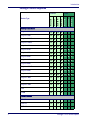
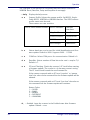
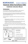
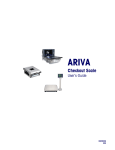
Datalogic Products Supported
.
Scanner
RS232 Std
RS232 SC
USB-COM
OEM USB
RS232 Std
RS232 SC
OEM USB
Device Type
Scale
Magellan 3200
Magellan 3300
Magellan 2200VS
Magellan 2300HS
Magellan 800i
Magellan 8100
Magellan 8200
Magellan 8300
Magellan 8400
Magellan 8500
Magellan 8500xT
Magellan 9500
Magellan 9800
Magellan 1000i
Magellan 1100i
Magellan 1400i
Duet
VS800
Table Top Scanner/Scales
Handheld Scanners
2
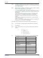
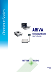
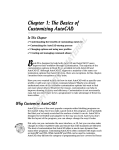
GD41XX
GM41XX
GBT41XX
Datalogic™ OPOS Service Objects
Installation
GBT44XX
GM44XX
QS6000+
QS2500
QS6500
QS6500BT
QD23XX
QD21XX
PD71XX
OEM USB
RS232 SC
RS232 Std
GD44XX
RS232 SC
OEM USB
Scale
USB-COM
Device Type
RS232 Std
Scanner
Handheld Scanners (continued)
Installation
Running the Install
Uninstall any previous DATALOGIC or PSC OPOS scanner/scale service
objects before proceeding with the installation of the DATALOGIC
OPOS Service Objects.
NOTE
DATALOGIC Service Objects are compatible with OPOS Common Control
Objects included in this package.
Installation can be performed in either of two ways: using a standard GUI
installation, or as a silent install from the Command Prompt.
GUI Installation
To install, please perform the following steps:
1.
User Manual
Download the most current install file for the DATALOGIC OPOS service
objects from the Datalogic website (www.datalogic.com).
3
Installation
2.
Double-click DatalogicOPOS.msi to run the install program.
3.
Follow the on-screen instructions to complete the installation.
Version and date fields will be different depending on the version of
the downloaded file.
NOTE
Silent Install from Command Prompt
To perform a “silent install,” open a command window and cd to the directory containing the DatalogicOPOS.msi file. Type the following command to execute the install process:
> DatalogicOPOS.msi /quiet
Silent Install mode does not install Common Control Objects.
NOTE
To install control objects during a silent install, type the following command:
> DatalogicOPOS.msi /quiet INSTALLCONTROLOBJECTS=1
4
Datalogic™ OPOS Service Objects
Utilities
Utilities
DualTest Utility
The Datalogic OPOS package contains a utility called DualTest that provides
customers with the ability to quickly connect and test the operation of a
Datalogic scanner/scale with the Datalogic service objects. Simple OPOS
operations such as Open, Claim, Enable, Read Weights, bar code scanning,
bar code type, Release, and Close can be exercised with this utility. DualTest
is a fully operational OPOS application which exercises the connection and
data path through the Common Controls and Service Objects to the physical
device.
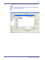
Scanner with DualTest
To connect to a Scanner, follow these steps after installing the OPOS package from Datalogic:
1.
User Manual
Select device:
5
Utilities
6
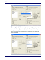
2.
Open Scanner:
3.
Claim:
Datalogic™ OPOS Service Objects
Utilities
User Manual
4.
Select Power Notify:
5.
Enable:
7
Utilities
8
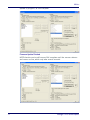
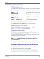
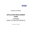
6.
Click the “DataEventEnable” button and check the “AutoDataEventEnable” box, and scan a bar code. The bar code data and
type will be displayed as shown here:
7.
Unplug the Scanner from the system. Power Status will show the new
scanner power state.
Datalogic™ OPOS Service Objects
Utilities
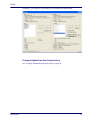
8.
Plug the scanner back into the system. Power Status will update again
with the new scanner power state.
Firmware Update with DualTest
The Datalogic OPOS Scanner Service Object supports the ability to update
firmware on select scanners in accordance with the UPOS Specification (version 1.9 and above). The user’s application may be written to take advantage of this capability in the service (see the UPOS specification for details).
In addition, the DualTest application bundled with Datalogic’s services supports this capability and may be used to upgrade firmware on select scanners. The following screen shots represent the steps used to upgrade
firmware on a scanner that supports this ability using DualTest.
IMPORTANT NOTE to OPOS programmers:
CAUTION
Prior to performing a firmware update on a scanner, the Scale Service Object should be closed. Failure to follow this step could lead to
firmware update failure and an inoperative scanner.
To perform the firmware update, start DualTest and follow the steps in the
previous section to Open and Claim the scanner. Then perform the following steps.
User Manual
9
Utilities
1.
OpenFile: Locate the firmware file on your machine or network.
Firmware files are interface and scanner specific and may be obtained
from Datalogic Tech Support.
NOTE
10
Datalogic™ OPOS Service Objects
Utilities
2.
Confirm Update Firmware:
Firmware Update Started
The Status field will update at every 1% of the upload. Depending on the
scanner interface and parameters such as baud rate, the update may take
from approximately 7 minutes to 40 minutes.
DO NOT disconnect the interface cable or power cable from the scanner
during the update!
User Manual
11
Utilities
Update in progress, at 62% complete:
Firmware Update Finished
NOTE that the service will stop at 99% complete until the scanner reboots
and comes on line, which may take several seconds.
12
Datalogic™ OPOS Service Objects
Utilities
Finalized: The scanner is now back on line and fully operational.
Firmware Update from the Command Line
See "Datalogic Remote Management Utility" on page 45.
User Manual
13
Utilities
Scale with DualTest
To connect to a Scale, follow these steps after installing the OPOS package
from Datalogic:
14
1.
Select Device:
2.
Open Scale:
Datalogic™ OPOS Service Objects
Utilities
User Manual
3.
Claim:
4.
Enable:
15
Utilities
5.
16
Read a weight:
Datalogic™ OPOS Service Objects
Utilities
Live Weight Display
The Datalogic OPOS Scale Service Object supports the ability to provide Live
Weight Display functionality in accordance with the UPOS Specification (version 1.9 and above). The user’s application may be written to take advantage of this capability in the service (see the UPOS specification for details).
In addition, the DualTest application bundled with Datalogic’s services supports this capability and may be used to demonstrate Live Weight Display
function with a Datalogic scanner/scale. The following screen shots represent the steps used to activate Live Weight Display with a scale using DualTest.
IMPORTANT NOTE to OPOS Programmers:
NOTE
PIDXScal_StatusNotify must be set TRUE while the scale is NOT
Enabled. As per the UPOS specification, setting PIDXScal_StatusNotify
TRUE after the scale has been Enabled will not activate the Live Weight Display
function in the scale service object.
To demonstrate Live Weight Display, start DualTest and follow the steps to
Open and Claim the scale, as described in the previous section. Then perform the following steps:
1.
User Manual
Set Status Notify True: Click the “Status Notify” check box.
17
Utilities
18
2.
Enable: (Live Weight Begins immediately / Zero Weight)
3.
Underweight: An under zero condition has occurred.
Datalogic™ OPOS Service Objects
Utilities
User Manual
4.
In motion: The scale is in motion and has not stabilized.
5.
Overweight: The scale’s weight capacity has been exceeded.
19
Utilities
20
6.
Stable Large Weight:
7.
Stable Small Weight:
Datalogic™ OPOS Service Objects
Registry
Registry
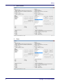
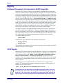
Windows Management Instrumentation (WMI) Compatible
Datalogic OPOS Service Objects provide WMI compatible Remote Management for certain scanners when properly configured. For scanners that support this data gathering capability, the Service Objects must be configured
via registry settings to provide scanner data to the WMI data store. There are
two registry settings that must be active to pull data from the scanner and
provide it to the WMI data store: “CheckIHSOnClaim” and “WMIOnClaim”
must both be set = 1. When these settings are active, each time the scanner
is “claimed” by an OPOS application, the service will query the scanner and
send the information to the WMI data store. Any WMI-data gathering application will then have access to the data. As noted in the registry section
below, these settings are defaulted to “active” upon installation. Note that
this process may have a small impact upon system performance.
The data provided to the WMI database follows the format as specified in
the UPOS specification, Appendix I, “Systems Management Information”,
which is modeled on the Common Information Model (CIM) from the DMTF.
This standard provides a means of Remote Management of Datalogic scanner/scales under the Windows Management Instrumentation process.
The default WMI repository:
root\CIMV2
contains two class definitions for statistics information:
• UPOS_Scanner
• UPOS_Scale
There will be one instance of each class per unique serial number identified
scanner used by an OPOS object.
OPOS Registry
Datalogic OPOS Service Objects use the Windows registry for configuration
of the OPOS software. When the OPOS package is installed, the installer creates registry entries under HKEY_LOCAL_MACHINE\SOFTWARE\OLEforRetail\ServiceOPOS; Scale and Scanner. Under each UPOS
category, there are named entries for each device. Under each name, there
are some user-configurable entries that control the operation of the OPOS
Service Objects.
The registry system on Windows 64 bit machines has changed where
'default' 32 bit application registry settings are stored. In the registry, all
settings will be found under:
[HKEY_LOCAL_MACHINE\SOFTWARE\WOW6432NODE\....]
NOTE
User Manual
Changing items in the registry does not change corresponding items in the scanner. For example, baud rate can be changed in the RS232Scanner registry, but the
baud rate in the scanner must be changed via programming label to match the
registry entry, or the Service Object will be unable to communicate to the scanner.
21
Registry
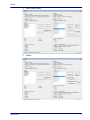
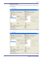
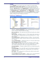
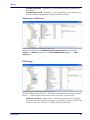
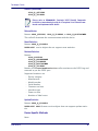
Scanner
Under SCANNER in the registry, there are a number of named entities:
HandScanner, MagellanSC, QS6000, and so forth. Note that some of
these are duplicates that have been maintained for legacy purposes: for
example, “HandScanner” and “USBHHScanner” refer to the same device (a
handheld scanner running OEM USB interface); “MagellanSC” is the same
as “SCRS232Scanner”; “TableScanner” and “USBScanner” are equivalent; QS6000 and RS232Scanner are equivalent, QSLScanner is a unique
entry. The following screen shots cover the important user-configurable
registry settings for each category of scanner.
HandScanner = USBHHScanner:
•
•
•
•
•
•
•
•
•
•
22
(Default) = DLOPOS.DLScanner – this is the default name used by the
service. The user should not edit this entry.
AbstractDevice – this represents the GUID and should not be edited
by the user.
Add01ToRSS – defaulted to active (1), if the scanner does not return a
“01” at the start of a Databar label, the service will add the “01” if this
item is active.
CheckIHSOnClaim – defaulted to active (1). When 1, the service will
request information-health-statistics data from the scanner each time
it is “claimed”.
ConvertBCDtoASCII – defaulted to active (1), the service will convert
any label sent in BCD format to ASCII.
DeviceNameOverride – this is the name reported by OPOS as the
“device name” in the OPOS object. If the user’s application is coded to
use a certain specific name, the user can insert that name here.
FirmwareUpdate – Firmware endpoint GUID, user should not modify
this entry.
FirmwareUsage – this is the USB “usage” for the firmware endpoint, in
decimal (the USB spec defines this in hexadecimal). User should not
modify this entry.
Pollrate – this is the period, in milliseconds, that the service polls
the scanner for connection.
ScanDataEqualScanDataLabel – default is off. This will make the
ScanData property always equal the ScanDataLabel property.
Datalogic™ OPOS Service Objects
Registry
•
•
•
•
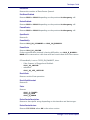
UPCEANCheckDigitCalc – defaulted to active, the service will calcu-
late the check digit for a UPC/EAN label if it is not present on the scanner interface, and append this to the data in the ScanDataLabel
property.
Usage – this is the USB “usage” for the scanner device. (The USB spec
defines this in hexadecimal). User should not modify this entry.
USBMonitor – defaulted to active, the service will periodically ensure
that the scanner and host “enable” state is the same.
WMIOnClaim – defaulted to active, the service will compile WMI data
upon “claim” of the device. This may slow down the claim process
slightly.
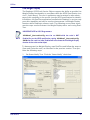
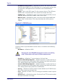
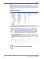
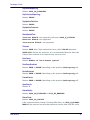
MagellanSC = SCRS232Scanner
Common fields as per Handheld scanner above; in addition the following
fields are:
•
BaudRate – default to 9600.
Changing this value REQUIRES changing the scanner to a matching
value – failure to do so will result in failure to communicate!
CAUTION
•
•
•
•
•
•
User Manual
DataBits – default to 7, same caveat as for baud rate.
OverrideUPCASuplimental – default not active; can be used in cer-
tain circumstances to differentiate label+addon from label only packet.
This setting would rarely need user modification.
OverrideUPCESuplimental – default not active; can be used in certain circumstances to differentiate label+addon from label only packet.
This setting would rarely need user modification.
Parity – defaults to Odd to match scanner default on SC RS232 interface, same caveat as for baud rate.
Port – defaults to COM1. User can change as needed to match system
com port.
RTSControl – defaulted to active. Service will set CTS line active at the
host port and leave it set high.
23
Registry
•
StopBits – defaulted to 1, same caveat as for baud rate.
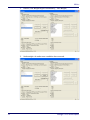
RS232Scanner = QS6000
Common fields as above; in addition the following field is:
•
IncludeCR – This will add a {0x0D} to the end of barcodes. Default
•
TransmitUnknown - when set to 0, the service will not send barcodes
to the application if the symbology is unknown. When set to 1, all barcode data will be sent to the application, regardless of the value of
ScanDataLabel (symbology type). Default is 0.
WarholParsing – defaults to not active. When using a QD21xx,
QD23xx, PD71xx, or GD41xx handheld scanner, the user should set
this to active and select the “RS232 OPOS” interface in the scanner
programming guide. This setting enables correct identification of Label
Ids from the scanner through the Service Object.
•
off.
QSLScanner
There are no unique fields for this scanner, but some of the settings default
to different values because of limited capabilities:
24
Datalogic™ OPOS Service Objects
Registry
•
•
FirmwareUpdate – defaults to 0; this device cannot be updated by
the service.
CheckIHSOnClaim – defaults to 0; this device does not support commands needed to determine scanner health and status.
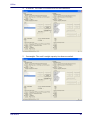
TableScanner = USBScanner
Settings are identical to USBHHScanner/HandScanner, except that
Usage = 18944 (4A00 hex), and DeviceNameOverride = “…USB
Scanner”.
RS232Imager
The RS232Imager utilizes a 115,200 baud rate and enhanced parsing capabilities. These registry items are turned on for this scanner type.
•
User Manual
UseVirtualPort – when set to 1, the service will look for a virtual
com port and ignore the Port number if it finds a virtual port (USB COM
device). If set to 0, the Port = COMn setting will be used.
25
Registry
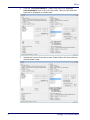
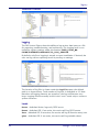
Scale
Under the SCALE in the registry, there are five named entities. Some are
redundant and have been maintained for legacy applications. The following
screen shots cover the important user-configurable settings for each category of scale.
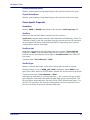
MagellanSC = SCRS232Scale
NOTE
•
•
•
IMPORTANT NOTE: COM port settings for this scale device are identical to the corresponding scanner names; this is because the two
devices share the same COM port and must use the same communication parameters. The same caveats apply to changing these values in the registry and scanner/scale – the settings must match.
CapStatusUpdate – defaulted to 1, this indicates that the scale service is capable of supplying Status Update events as per the UPOS
Live Weight Display description in the scale section of the UPOS
spec.
CapZeroScale – defaulted to not active. The Single Cable scale does
not support host zeroing of the scale.
LiveWeightInterval – default to 500; this is the poll rate in milliseconds that the scale service polls the scale for weight in the case of
Live Weight Display enabled.
The user should never set this value below 250 msec.
NOTE
26
Datalogic™ OPOS Service Objects
Registry
•
Metric – defaulted to 0. This setting controls the type of Weight
Request sent to the scale by the service; the default is English Weight
Request. The user can set this to 1 to obtain Metric weights.
The scanner/scale must be programmed to the same data type or
weight requests will fail.
CAUTION
•
ZeroValid – defaulted to Active. When active, the service will deliver a
stable zero weight as a valid weight to the host. When set to 0, the service will follow the pre-1.13 UPOS specification and not deliver zero as
a valid weight (this setting is used by some customers to maintain a
live weight display outside of the UPOS specification).
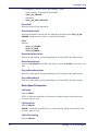
RS232Scale
•
•
CapZeroScale – defaulted to Active, the scale service can zero the
scale through the interface.
Port – defaulted to COM2. The user can select the desired COM port
for their system.
This MUST be a different COM port than the associated Scanner port.
NOTE
•
•
•
•
User Manual
BaudRate – defaulted to 9600. The user should not change this setting, as the scale baud rate is NOT configurable.
DataBits – set to 7. The user should not change this setting, as the
scale data bits are NOT configurable.
Parity – set to Even. The user should not change this setting, as the
scale parity is NOT configurable.
StopBits – set to 2. The user should not change this setting, as the
scale stop bits are NOT configurable.
27
Registry
TableScale = USBScale
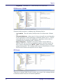
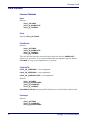
Logging
The DLS Service Objects have the ability to log various data items to a file
for reporting, troubleshooting, and monitoring. The logging level is controlled by registry settings under the location: HKEY_LOCAL_MACHINE\SOFTWARE\DATALOGIC\DL_OPOS_SERVICE.
By default, only Error logging is turned on upon installation. If desired, the
user can log various reporting levels by turning on settings.
The location of log files is shown under the LogFile name; the default
path is as shown above. Total number of log files is defaulted to 10. Note
that when all logging features are turned on, the logs will become very
large. Logging should normally be left in the “error” mode only to conserve
system resources.
Levels
Error – defaulted Active; logs only OPOS errors.
Event – defaulted Off; if set active, the service will log OPOS events.
Func – defaulted Off; if set active, the service will log all function entry/exit.
gVar – defaulted Off; if set active, the service will log variable values.
28
Datalogic™ OPOS Service Objects
Registry
Registry Service Properties
•
•
•
•
•
•
•
•
•
•
User Manual
CompanyName: Value is the name displayed in the Service Object.
This value should not be changed.
DeviceName: Value is the name displayed in the Service Object. This
value should not be changed.
LogFile: Contains the location where the log files are written.
Changing this value may cause logging failures under Windows 7 and
newer operating systems.
MSDELAY: Contains the global lock feedback timeout. This value
should not be changed.
NumberofFirmwareRetries: Value is the number of times to retry
connecting to the scanner after firmware update. This value should not
be changed.
ServiceName: Value contains the name displayed in the Service
Object. This value should not be changed.
SingleCableSplitter: Contains the location of the RS232 Splitter
program. This value should not be changed.
StatsFile: Contains the directory to store the .PRF file. Changing
this value may cause logging failures under Windows 7 and newer
operating systems.
TotalFiles: Controls how many log files to maintain before rolling
over. It is recommended not to change this value.
UpdateStatsEveryMinutes: Controls how many minutes between
updates of the StatsFile and WMI store. If set to a non-zero value, the
OPOS Service Object will query the scanner for statistical information
every N minutes, where N is the value of this control, and update the
stats file and WMI store.
29
Registry
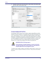
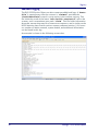
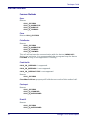
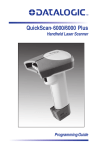
Additional Logging
The DLS OPOS Service Object can also create two additional logs. A “StatsFile” is created every time the scanner is “claimed”, provided the
“CheckIHSOnClaim” control is set to active in the scanner registry. This
file holds the result of the latest “info-health-statistics” call to the
scanner, and is overwritten upon each “claim”. This file holds information
about the scanner that may be of interest to customers, and is similar to the
UPOS Statistics data. Entries such as scanner software revision, S/N, hourson, number of labels scanned, system health, and additional information
can be found in this log.
An example is shown in the following screen shot:
30
Datalogic™ OPOS Service Objects
Developers Guide
Developers Guide
OPOS service objects export a uniform interface; however there may be
slight differences between the same types of devices from different vendors
and models. Queries of OPOS properties reveal these differences. Below
listed properties, methods, and events are DATALOGIC device specific
return values. Other DATALOGIC service objects with different interfaces
may produce slightly different results. Developers are advised to consider
all error conditions in designing an application.
Scanner Properties
Common Properties
AutoDisable:
Returns TRUE or FALSE depending on the previous SetProperty call.
BinaryConversion:
Returns TRUE or FALSE depending on the previous SetProperty call.
CapCompareFirmwareVersion:
Returns TRUE (also depends on the firmware and model of the scanner).
CapPowerReporting:
Returns OPOS_PR_STANDARD
CapStatisticsReporting:
Returns TRUE (also depends on the firmware and the model of the scanner).
CapUpdateFirmware:
Returns TRUE (also depends on the firmware and model of the scanner).
CapUpdateStatistics:
Returns FALSE.
CheckHealthText:
Internal HCheck: will return health string
External HCheck: not supported
Interactive HCheck: not supported
This property is empty before the first call to the CheckHealth method.
Claimed:
Returns TRUE after Claim method has been called. FALSE otherwise.
DATALOGIC devices are exclusive. It is recommended that a program keep
the device Claimed as long as the application is running.
User Manual
31
Developers Guide
DataCount:
Returns the number of Data Events Queued.
DataEventEnabled:
Returns TRUE or FALSE depending on the previous SetProperty call.
DeviceEnabled:
Returns TRUE or FALSE depending on the previous SetProperty call.
FreezeEvents:
Returns TRUE or FALSE depending on the previous SetProperty call.
OpenResult:
Returns 0.
PowerNotify:
Returns OPOS_PN_DISABLED or OPOS_PN_ENABLED.
PowerState:
Returns OPOS_PS_ONLINE.
If the communication channel is having difficulties, an OPOS_E_NOHARDWARE will be returned on calls that send and receive data from the scanner.
If PowerNotify is set to "OPOS_PN_ENABLED", then:
•
If the Scanner is Plugged and Enabled:
•
otherwise:
OPOS_PS_ONLINE
OPOS_PS_OFF_OFFLINE
ResultCode:
Returns result of last operation.
ResultCodeExtended:
Returns 0
State:
Returns
OPOS_S_CLOSED
OPOS_S_IDLE
OPOS_S_ERROR
DeviceServiceDescription:
Returns a descriptive string depending on the interface and device type.
DeviceServiceVersion:
Returns 101200XX. where XX is the minor version.
32
Datalogic™ OPOS Service Objects
Developers Guide
PhysicalDeviceDescription:
Returns a descriptive string depending on the interface and device type.
PhysicalDeviceName:
Returns a descriptive string depending on the interface and device type.
Device Specific Properties
DecodeData:
Returns TRUE or FALSE depending on the previous SetProperty call.
ScanData:
Holds the raw scanned data received from the scanner.
ScanData property always has bar code data when a DataEvent is fired. For
Tabletop scanners, the bar code data may be sent across the USB interface
as uncompressed Binary Coded Decimal (BCD), depending upon scanner
configuration and bar code type.
ScanDataLabel:
Holds the scanned and decoded data from the scanner if DecodeData
property is TRUE. If the decoded data did not contain a check digit, the
scanner service will add the check digit to ScanDataLabel for EAN/UPC
bar codes.
Contains data if DecodeData is TRUE.
ScanDataType:
Returns scanned data type of the most recent label from the scanner.
Returned value is one of SCAN_SDT_XXXX constants, where XXXX is the
type of the label. Refer to OPOS Scanner header file for the numerical values.
Contains label type if DecodeData is TRUE.
Label type as reported on scanner interface — the scanner assigns a label
type identifier and sends this with the label data across the interface. The
Service Object translates this into one of the OPOS defined label types. For
the RS-232 interface, the scanner configuration must be correctly set for
the Service Object to properly identify label type.
User Manual
33
Developers Guide
Scanner Methods
Common Methods
Open:
Returns
OPOS_SUCCESS
OPOS_E_NOSERVICE
OPOS_E_NOEXIST
OPOS_E_ILLEGAL
Close:
Returns OPOS_SUCCESS
ClaimDevice:
Returns
OPOS_SUCCESS
OPOS_E_NOSERVICE
OPOS_E_ILLEGAL
OPOS_E_CLAIMED
This call will activate the communication with the device. DATALOGIC
devices are exclusive. It is recommended that a program keep the device
Claimed as long as the application is running.
CheckHealth:
OPOS_CH_INTERNAL is supported.
OPOS_CH_EXTERNAL is not supported.
OPOS_CH_INTERACTIVE is not supported.
Returns
OPOS_SUCCESS
CheckHealthText property will hold the text result of this method call.
ClearInput:
Returns
OPOS_SUCCESS
OPOS_E_DISABLED
OPOS_E_NOTCLAIMED
DirectIO:
Returns
OPOS_SUCCESS
OPOS_E_NOTCLAIMED
34
Datalogic™ OPOS Service Objects
Developers Guide
DirectIO: (continued)
OPOS_E_OFFLINE
OPOS_E_ILLEGAL
Please refer to DR90000351, Datalogic UPOS DirectIO Commands
(available at www.datalogic.com) for a complete list of DirectIO commands and implementation details.
NOTE
ReleaseDevice:
Returns OPOS_SUCCESS, OPOS_E_ILLEGAL, or OPOS_E_NOTCLAIMED.
This call will deactivate the communication with the device.
ResetStatistics:
Returns OPOS_E_ILLEGAL
DATALOGIC service objects do not support reset statistics.
RetrieveStatistics:
Returns
OPOS_SUCCESS
OPOS_E_NOHARDWARE
OPOS_E_DISABLED
OPOS_E_NOTCLAIMED
OPOS_E_ILLEGAL
Results of the RetrieveStatistics call are written to the OPOS Log and
returned as per the OPOS spec.
Supported statistics are:
•
•
•
•
•
•
•
•
Device category
Manufacturer
Model number
Serial Number
Firmware revision
Interface type
Power on time
Number of label scans
UpdateStatistics:
Returns OPOS_E_ILLEGAL
DATALOGIC OPOS Scanner service object does not support update statistics.
Device Specific Methods
None.
User Manual
35
Developers Guide
Scanner Events
Common Event
DataEvent:
This event fires when a label is forwarded from scanner.
DirectIOEvent:
Not supported.
ErrorEvent:
Not used.
StatusUpdateEvent:
During the Firmware Update Process the following Status Update Events will
be delivered:
OPOS_SUE_UF_PROGRESS
OPOS_SUE_UF_COMPLETE
OPOS_SUE_UF_COMPLETE_DEV_NOT_RESTORED
OPOS_SUE_UF_FAILED_DEV_OK
OPOS_SUE_UF_FAILED_DEV_UNRECOVERABLE
OPOS_SUE_UF_FAILED_DEV_NEEDS_FIRMWARE
OPOS_SUE_UF_FAILED_DEV_UNKNOWN
If PowerNotify is set to OPOS_PN_ENABLED when the scanner is claimed:
•
On Enable and/or If the current Power State Changes:
OPOS_SUE_POWER_ONLINE
OPOS_SUE_POWER_OFF_OFFLINE
Device Specific Events:
None.
Scale Properties
Common Properties
AutoDisable:
Returns TRUE or FALSE depending on the previous SetProperty call.
BinaryConversion:
Returns TRUE or FALSE depending on the previous SetProperty call.
CapCompareFirmwareVersion:
Returns FALSE.
36
Datalogic™ OPOS Service Objects
Developers Guide
CapPowerReporting:
Returns OPOS_PR_STANDARD.
CapStatisticsReporting:
Returns FALSE.
CapUpdateStatistics:
Returns FALSE.
CapUpdateFirmware:
Returns FALSE.
CheckHealthText:
Internal HCheck: not supported, will return OPOS_E_ILLEGAL.
External HCheck: not supported.
Interactive HCheck: not supported.
Claimed:
Returns TRUE after Claim method has been called. FALSE otherwise.
DATALOGIC devices are exclusive. It is recommended that the device be
claimed and continue to be claimed thru-out a session.
DataCount:
Returns Number of Data Events Queued.
DataEventEnabled:
Returns TRUE or FALSE depending on the previous SetProperty call.
DeviceEnabled:
Returns TRUE or FALSE depending on the previous SetProperty call.
FreezeEvents:
Returns TRUE or FALSE depending on the previous SetProperty call.
OpenResult:
Returns 0.
PowerNotify:
Returns OPOS_PN_DISABLED or OPOS_PN_ENABLED.
PowerState:
Returns OPOS_PS_ONLINE.
If the communication channel if having difficulties, an OPOS_E_NOHARDWARE will be returned on calls that send and receive data from the scale.
User Manual
37
Developers Guide
If PowerNotify is set to "OPOS_PN_ENABLED", then:
•
If the Scanner is Plugged and Enabled:
•
otherwise:
OPOS_PS_ONLINE
OPOS_PS_OFF_OFFLINE
ResultCode:
Returns result of last operation.
ResultCodeExtended:
Returns extended result if the last operation produced an OPOS_E_EXTENDED. Otherwise this value is considered invalid.
State:
Returns
OPOS_S_CLOSED
OPOS_S_IDLE
OPOS_S_ERROR
DeviceServiceDescription:
Returns a descriptive string depending on the interface and device type.
DeviceServiceVersion:
Returns 10YY0XXX where YY is the major version and XXX is the minor version.
PhysicalDeviceDescription:
Returns a descriptive string depending on the interface and device type.
PhysicalDeviceName:
Returns a descriptive string depending on the interface and device type.
Device Specific Properties
CapDisplay:
Returns TRUE.
TRUE is returned regardless of a remote display being connected to the
scanner/scale or not.
CapDisplayText:
Returns FALSE.
FALSE is returned regardless of a remote display being connected to the
scanner/scale or not.
CapPriceCalculating:
Returns FALSE.
38
Datalogic™ OPOS Service Objects
Developers Guide
CapStatusUpdate:
Returns TRUE.
CapTareWeight:
Returns FALSE.
CapZeroScale:
Returns TRUE.
AsyncMode:
Returns TRUE or FALSE depending on the previous SetProperty call.
MaxDisplayTextChars:
Returns 0.
MaximumWeight:
Returns 15000 in metric mode.
Returns 30000 in pound mode.
ScaleLiveWeight:
Updated if LiveWeight is enabled.
StatusNotify:
If CapStatusUpdate is TRUE, the application can set StatusNotify to
either SCAL_SN_DISABLED or SCAL_SN_ENABLED.
SalesPrice:
Returns 0 currency.
TareWeight:
Returns 0.
UnitPrice:
Returns 0 currency.
WeightUnit:
Returns SCAL_WU_KILOGRAM in metric mode.
Returns SCAL_WU_POUND in pound mode.
User Manual
39
Developers Guide
Scale Methods
Common Methods
Open:
Returns
OPOS_SUCCESS
OPOS_E_NOSERVICE
OPOS_E_ILLEGAL
Close:
Returns OPOS_SUCCESS.
ClaimDevice:
Returns
OPOS_SUCCESS
OPOS_E_NOSERVICE
OPOS_E_ILLEGAL
OPOS_E_CLAIMED
This call will activate the communication with the device. DATALOGIC
devices are exclusive. It is recommended that a program keep the device
Claimed as long as the application is running.
CheckHealth:
OPOS_CH_INTERNAL is not supported.
OPOS_CH_EXTERNAL is not supported.
OPOS_CH_INTERACTIVE is not supported.
Returns
OPOS_SUCCESS
OPOS_E_NOTCLAIMED
OPOS_E_DISABLED
OPOS_E_ILLEGAL
CheckHealthText property will hold the text result of this method call.
ClearInput:
Returns
OPOS_SUCCESS
OPOS_E_DISABLED
OPOS_E_NOTCLAIMED
40
Datalogic™ OPOS Service Objects
Developers Guide
DirectIO:
Returns
OPOS_E_NOTCLAIMED
OPOS_E_OFFLINE
OPOS_E_ILLEGAL
Please refer to DR90000351, Datalogic UPOS DirectIO Commands
(available at www.datalogic.com) for a complete list of DirectIO commands and implementation details.
NOTE
ReleaseDevice:
Returns OPOS_SUCCESS.
OPOS_E_ILLEGAL if the device has not been claimed.
This call will deactivate the communication with the device. It is recommended that a program keep the device Claimed until an application quits.
ResetStatistics:
Returns OPOS_E_ILLEGAL
DATALOGIC OPOS Scale service objects do not support reset statistics.
UpdateStatistics:
Returns OPOS_E_ILLEGAL.
DATALOGIC OPOS Scale service objects do not support update statistics.
User Manual
41
Developers Guide
Device Specific Methods
GetSalesPrice:
Returns 0
Not implemented
GetUnitPrice:
Returns 0
Not implemented
SetUnitPrice:
Returns OPOS_E_ILLEGAL
Not implemented
DisplayText:
Returns OPOS_E_ILLEGAL
ReadWeight:
Returns
OPOS_SUCCESS
OPOS_E_EXTENDED
OPOS_E_TIMEOUT
CANCELLED
OPOS_E_NOTCLAIMED
OPOS_E_DISABLED
OPOS_E_OFFLINE
OPOS_E_ILLEGAL
OPOS_E_FAILURE
OPOS_E_BUSY
OPOS_E_NOHARDWARE
If the result is OPOS_SUCCESS valid weight is returned.
If the result is OPOS_E_EXTENDED extended status will return either
OPOS_ESCAL_OVERWEIGHT or OPOS_ESCAL_UNDER_ZERO in result code
extended.
If the result is OPOS_E_TIMEOUT there was not valid settled weight on the
platter before the timeout. Weight and the ExtendedStatus values are
invalid.
The Weight Unit entry in the Registry must match the Scale configuration (Metric or English). See the Registry Description section starting
on page 21.
NOTE
ZeroScale:
Returns
OPOS_SUCCESS
OPOS_E_NOHARDWARE
OPOS_E_OFFLINE
OPOS_E_DISABLED
OPOS_E_NOTCLAIMED
42
Datalogic™ OPOS Service Objects
Developers Guide
Scale Events
Common Event
DataEvent:
Used for asynchronous weight requests
DirectIOEvent:
Not supported
ErrorEvent:
Used if a cancel weight is called during an asynchronous weight request
StatusUpdateEvent:
Supported as per LiveWeightDisplay as documented in the UPOS specification.
If PowerNotify is set to OPOS_PN_ENABLED when the scanner is claimed:
•
On Enable and/or If the current Power State Changes:
OPOS_SUE_POWER_ONLINE
OPOS_SUE_POWER_OFF_OFFLINE
Device Specific Events
None
User Manual
43
Developers Guide
NOTES
44
Datalogic™ OPOS Service Objects
Appendix A
Datalogic Remote Management Utility
Overview
Datalogic Remote Management Utility (DLRMU) is a command line-driven
program that uses the Datalogic OPOS drivers to perform firmware/configuration updates. The command line-driven interface provides an easy way to
perform updates via batch files.
This document will provide information on operation, command line options as
well as command line and batch file examples.
Operation
DLRMU supports the following interfaces: Standard RS232, Single-Cable
RS232,USBCOM and USBOEM.
Operating System Requirements: Windows XP (.NET Version 3.5 and up),
Windows 7 (32,64 bit), Windows 8
If DLRMU is run from the command line without any command line options it
will return the Help file contents to the screen.
Each command line execution will return a status. A zero status indicates a
successful operation and non-zero status indicates an error.
The program creates a log (dlslog.txt) that is located in the same folder
as the DLRMU program. This log is appended with each execution.
DLRMU also creates a scanner information file (.prf) that contains all the
information gathered during the last query. This file is overwritten each time
the scanner is queried so that it only contains the most current information.
This file is used for remote management data collection. This file is located
in C:\ProgramData\Datalogic\Logs. The file name will be the same as
the OPOS profile called on the command line, such as “USBHHScanner.prf”.
The new firmware/configuration files that are going to be downloaded into
the scanner should be in the same folder as DLRMU. If a different location is
chosen, the full path to the file must be entered on the command line.
All options not defined in the command line use the default values:
COM 0, Baud 9600, Data Bits 7, Parity Odd, Stop Bits 1
User Manual
45
Operation
If a COM port is not specified it is assumed that the scanner interface is
USBOEM. Baud, Data bits, Parity and Stop Bits do not apply.
--help
Display the help screen.
-a x
Scanner Profile. Selects the scanner profile: Std RS232, SingleCable RS232, USBCOM or USBOEM interface. The OPOS scanner
profile name must be used.
These names are case sensitive.
List of OPOS Scanner Profiles:
RS232 Interfaces
USBOEM
Interfaces
MagellanSC
HandScanner
SCRS232Scanner
TableScanner
RS232Scanner
USBHHScanner
RS232Imager
USBScanner
-b x
Selects baud rate x to be used for initial identification and firmware update. Default is 9600. Supports 2400 – 115200
-c x
COM Port. Selects COM port x for communication. Default is 0.
-d x
Data Bits. Selects number of Data bits to be used. x may be 7,8
Default is 7.
-e x
EC Level Checking. Checks the scanner’s EC Level before starting
a firmware update. The x value is a 4 character numeric string.
The EC Level should match the new firmware file.
If the scanner responds with an EC Level “equal to” or “greater
than” the value on the command line the firmware update will be
aborted.
If the scanner responds with an EC Level “less than” the value on
the command line the firmware update will continue.
Return Codes:
1 = OLDER
2 = SAME
3 = NEWER
4 = DIFFERENT
5 = UNKNOWN
-E, --Enabled. Leave the scanner in the Enabled state after firmware
update. Default = true.
46
Datalogic™ OPOS Service Objects
Operation
-f x
File Name. Update the scanner with the firmware or config file x.
The scanner's ID, health, and status is recorded before and after
the firmware update.
-F x
Model Number Validation. Validate the scanner’s model number
before performing firmware/config update.
x = scanner model number. The model number entered on the
command line is compared to the model number extracted from
the scanner.
If the model numbers match the firmware/config update will
proceed, if not, no firmware/config update is performed.
This option is only used when performing a firmware/config
update. If this switch is not present, no comparison is performed and
update will proceed.
If the "-r" short model number option is used the command line
must have one of the models listed above.
***The short model numbers must be quoted on the command line***
-l x
Log File Name. x sets the log file name. Default is dlslog.txt.
-O
List Options.
-p x
Parity. Selects parity x to be used for communication with the
scanner.
x may be:
'n'
'o'
'e'
'm'
's'
-r
User Manual
no parity
odd
even parity
mark parity
space parity
Short Model Names. Specifies the use of Short Model Names.
“2200 VS"
"2300 HS"
"8200 SO"
"8200 SS"
"8300 SO"
"8300 SS"
"8400 SO"
"8400 SS"
"8500 SO"
"8500 SS"
"8500XT SO"
"8500XTS SO"
"8500XT SS"
"8500XTS SS"
“9300i SO”
“9300iSS”
"9400i SO"
"9400i SS"
"9500 SO"
"9500 SS"
"9800i SO"
"9800i SS"
SO = Scanner Only
SS = Scanner Scale
47
Operation
-s x
Stop Bits. Selects the number of Stop Bits. x may be 1,2, Default
is 1.
-t x
Selects baud rate x to be used for identification following a
firmware update.
The new firmware and configuration may change the baud
rate of the scanner.)
NOTE
Default is 9600. Supports 2400 – 115200
-v x
48
Timeout Delay. x sets the Timeout Delay in Seconds. Controls
the amount of time the program will wait for the scanner to
come back online after an update. The minimum is 10. Default is
60.
Datalogic™ OPOS Service Objects
Operation
Examples of Command Line Entries:
USE: Retrieving Scanner ID.
The DLRMU program will automatically query the scanner for ID information.
The following examples show how to query the three supported serial interfaces:
DLRMU -c 5 -a
SCRS232Scanner
(Single-Cable RS232 Scanner, COM
5)
DLRMU –c 18 –a
RS232Imager
(USBCOM Scanner, virtual COM 18)
DLRMU -c 1 -a
RS232Scanner –p N -d 8
(RS232 Scanner, COM 1, No Parity,
8 databits)
DLRMU –a USBHHScanner
(USBOEM, Handheld Scanner)
The information gathered will be displayed on screen.
The <scanner profile name>.prf file will also be updated.
USE: Retrieving Scanner ID at 115200.
To query a Single-Cable scanner for ID information at 115200.
DLRMU -c 5-b 115200 –a SCRS232Scanner
USE: Scanner Firmware Update.
The -f option is used to perform a firmware update. The filename of the
firmware update image follows the "-f" option.
For example, to update a Single-Cable RS232 scanner connected to COM2,
the following command may be used:
DLRMU -c 2 -a SCRS232Scanner -f DRxxxxxxxx.s37
DLRMU -c 2 -a SCRS232Scanner -F 868005211-0421000R
-f DRxxxxxxxx.s37
The command above will download the firmware at the default 9600 baud
rate and will take approximately 30 minutes to complete.
USE: Scanner Firmware Update with Model Number Validation.
The -F option validates the scanners model number before updating the
firmware.The long model number follows the -F option.
The -f option is used to perform a firmware update.
The filename of the firmware update image follows the -f option.
For example, to update a scanner with a model number of 8680052110421000R and connected to COM2, the following command may be used:
User Manual
49
Operation
DLRMU -c 2–a SCRS232Scanner -F 868005211-0421000R -f
DRxxxxxxxx.s37
The command above will download the firmware at the default 9600 baud
rate and will take anywhere from 20 minutes to 1hour to complete.
The file size determines the amount of time it takes.
USE: Scanner Firmware Update with Short Model Number
Validation.
The -r option specifies the use of short model numbers.
The -F option validates the scanners model number before updating the
firmware.The short model number follows the "-F" option.
The -f option is used to perform a firmware update. The filename of the
firmware update image follows the "-f" option.
For example, to update a scanner with a short model number of 8500XTS SS
and connected to COM2, the following command may be used:
DLRMU -c 2 -a SCRS232Scanner -r -F "8500XTS SS" -f
DRxxxxxxxx.s37
***The short model numbers must be quoted on the command line***
The command above will download the firmware at the default 9600 baud
rate and will take anywhere from 20 minutes to 1hour to complete. The file
size determines the amount of time it takes.
USE: Scanner Firmware Update with KeepConfig1 at two baud rates.
This example uses two different baud rates to reduce the amount of time it
takes to perform the update. A download at 9600 baud that takes 30 minutes can be reduced to 6-7 minutes at 115200 baud.
The s37 firmware file in this example does not contain a config file. It is
using KeepConfig to maintain all scanner settings. This example uses two
unique .s37 files that contain a single configuration item to change the
scanner’s baud rate. DLRMU must communicate with the scanner at both of
these baud rates so both must be specified on the command line.
The example contains three command line strings, the first queries the
scanner, validates the scanners model and changes the scanner’s baud to
115200.
The second updates the firmware at 115200.
The third returns the scanner to 9600 baud and validates the update was a
success.
String 1:
DLRMU -c 1 -a SCRS232Scanner -b 9600 -t 115200 r -F "8500XTS SS" -f 115200.s37
1. KeepConfig is required when performing host download on the 83/
8400 and 8500Xtscanner/scales.
50
Datalogic™ OPOS Service Objects
Operation
Validates short model name, communicates at 9600 baud for
scanner ID and file download.
Communicates at 115200 for scanner ID and validates baud
change.
String 2:
DLRMU -c 1DLRMU -c 1 -a SCRS232Scanner -b 115200
-t 115200 -f DRxxxxxxxx.s37.
Communicates at 115200 baud for scanner ID and file download.
Communicates at 115200 for scanner ID and to validate firmware update.
String 3:
DLRMU -c 1 -a SCRS232Scanner -b 115200 -t 9600 f 9600.s37
Communicates at 115200 baud for scanner ID and file download.
Communicates at 9600 for scanner ID and to validate baud
change.
These three command strings can be used together in a batch file:
DLRMU -c 1 -a SCRS232Scanner -b 9600 -t 115200 -r F "8500XTS SS" -f 115200.s37
DLRMU -c 1 -a SCRS232Scanner -b 115200 -t 115200 -f
DRxxxxxxxx.s37
DLRMU -c 1 -a SCRS232Scanner -b 115200 -t 9600 -f
9600.s37
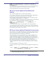
Real World Batch file
The following batch file is an example of how DLRMU can be used to target
specific scanners and perform updates across an enterprise. In this example,
the customer had over 1000 self-checkout lanes which utilized 3 different
Datalogic Scanner/Scales (Mgl9500,Mgl8500Xt, Mgl9800i). Two of the scanners required updating and the third did not. This batch file determines if
the scanner is one of the two needing an update or not, then loads the
appropriate firmware for the scanner found. This batch file combines many
of the DLRMU features to form a very powerful update solution.
•
•
•
•
•
User Manual
Queries the scanner and gathers Information, Health and Statistics.
Validates that the responding scanner is one of the two desired models.
Uses “Short Model Names” and “Model Number Validation.”
Validates the scanner needs updating. Uses the “EC Level Checking.”
Checks command status to make decision on which firmware to load.
Changes baud rate to 115200 to increase the update speed.
51
Operation
•
Changes baud rate back to 9600 for customer’s application (8500Xt
only).
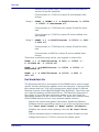
set comport=2
DLRMU -a SCRS232Scanner -c %comport% -b 9600 -r -F
"8500XTS SS" --EC 0939
if "%errorlevel%"=="0" goto download_8500xts
DLRMU -a SCRS232Scanner -c %comport% -b 9600 -r -F
"9800i SS" --EC 0340if "%errorlevel%"=="0" goto
download_9800i
goto exit
:download_8500xts
DLRMU -a SCRS232Scanner -c %comport% -b 9600 -t
115200 -r -F "8500XTS SS" -f8500_115200.s37
DLRMU -a SCRS232Scanner -c %comport% -b 115200 -t
115200 -r -F "8500XTS SS" f8500_9801_SCRS232_ULE.s37
DLRMU -a SCRS232Scanner -c %comport% -b 115200 -t
9600 -r -F "8500XTS SS" -f8500_9600.s37
goto exit
:download_9800i
DLRMU -a SCRS232Scanner -c %comport% -b 9600 -t
115200 -r -F "9800i SS" -f9800i_115200.s37 -v 10
DLRMU -a SCRS232Scanner -c %comport% -b 115200 -t
9600 -r -F "9800i SS" -fMR21_0494_KRSCO.s37 -v 10
goto exit
:exit
52
Datalogic™ OPOS Service Objects
Operation
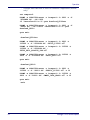
Unsupported Features
These features are planned to be added in the future
-m x
-n x
STX Character. Specifies the start character used in the single-
cable message format. If omitted, the default value matches the
DLS scanner default of 83 (decimal for ASCII 'S'). The value x is
in decimal.
ETX Character. Specifies the end character used in the singlecable message format.
If omitted, the default value matches the DLS scanner default of
13 (decimal for ASCII Carriage Return). The value x is in decimal.
-x
User Manual
BCC Character. Specifies that a BCC is to be used in the singlecable message format. BCC character is calculated and transmitted with the data packets.
53
Operation
NOTES
54
Datalogic™ OPOS Service Objects
www.datalogic.com
©2008-2015 Datalogic ADC, Inc. All rights reserved.
Datalogic and the Datalogic logo are registered trademarks of
Datalogic S.p.A. in many countries, including the U.S.A. and the E.U.
Datalogic ADC, Inc.
959 Terry Street | Eugene |OR 97402 | USA
Telephone: (1) 541-683-5700 | Fax: (1) 541-345-7140
820025614
(Rev K)
September 2015