1
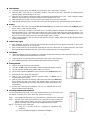
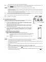
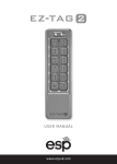
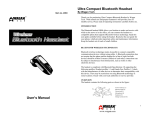
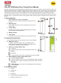
Yale 22116 Wireless Door Contact User Manual The Door Contact monitors the opening/closing of specified devices (e.g. door or window). The Door Contact is fixed to the monitored device frame with an actuating magnet fixed to the device. When the door or window opens, the magnet moves away from the Door Contact, activating an internal magnetic switch causing the Door Contact to transmit an alarm signal to the Central Panel. The device also has the capabilities of communicating signal problems along with low battery situations. The Door Contact design consists of a cover and base. The cover contains all electronics and the base provides a means for fixing the device. An enclosed PCB tamper switch provides tamper protection against unauthorized device opening and/or removal. Parts Identification 1. LED indicator a.k.a. Learn / Test button Press the Test button to transmit learning code or enter test mode for 3 min. 2. Mounting Holes Used to fixed and screw the Door Contact directly onto the Door Frame or Wall. 3. Tamper Switch Provides tamper protection against unauthorized device opening and/or removal from mounting surface. 4. 5. Battery Insulator Fixing Screw Screw used to secure the top and bottom case of the Door Contact. Internal Switch and Terminal White cap Loosen the bottom fixing screw and remove the cover to reveal terminal as shown. 6. Extension Terminal In addition to the built-in magnet switch, an additional 2-pin dry contact terminal is provided for an extension magnet switch or any device with N.C. (Normally Closed) functionality. 7. Supervision Jumper Switch (JP2) Jumper ON White cap - When the jumper is set as ON, the Supervision function is disabled. (Factory Default) Jumper OFF - When the jumper is set as OFF, the Supervision function is enabled. 8. Internal Magnetic Switch Jumper Switch (JP3) Jumper ON (Factory default) - When the jumper is set as ON, the Internal Magnetic Switch is disabled. Only the device connected to Extension Terminal will activate DC-15SL / DCA-15SL Jumper OFF: - When the jumper is set as OFF, the Internal Magnetic Switch is enabled. (Factory Default) Accessories Included a) 1 Magnet b) 2 White Caps c) 2 Screws d) 2 Wall Plugs e) 1 Magnet double-sided adhesive tape pad f) 2 Magnet mounting screws 1 LED Indicator In Normal Operation Mode, the LED will not light when DC-15SL / DCA-15SL is activated. When DC-15SL / DCA-15SL is in Low battery condition, every time the DC-15SL / DCA-15SL is activated (device opened/ closed), the LED will light on for 2 sec. When the cover is opened or the tamper switch is triggered, the LED will light on for 2 sec. When a tamper condition persists, every time the Door Contact is activated, the LED will light on for 2 sec. When DC-15SL / DCA-15SL is in Test mode, the LED will light up every time it is activated. When battery voltage reaches 2.2V, DC-15SL / DCA-15SL will stop all function, the LED will flash every 4 seconds. Battery The DC-15SL / DCA-15SL uses one 1/2 AA, 3V Lithium battery as its power source. Please note: ALWAYS replace battery with the correct size and voltage. DC-15SL / DCA-15SL can detect if the battery is low. Low battery detection operates at a threshold of 2.4V ± 3%.. When the Battery is low, a low battery signal will be sent to the Control Panel along with regular transmission. The LED will light up when DC-15SL / DCA-15SL is activated under low battery status. When battery voltage reaches 2.2V, DC-15SL / DCA-15SL will stop all function, the LED will flash every 4 seconds. When changing batteries, after removing the old batteries, press the Tamper Switch twice to fully discharge before inserting new batteries. Supervisory Signal After installation, DC-15SL / DCA-15SL will automatically transmit Supervisory Signals periodically to the Control Panel at random intervals of 30 ~ 50 minutes. If the Control Panel has not received the signal from the DC-15SL / DCA-15SL for a preset period time, the Control Panel will indicate that particular DC-15SL / DCA-15SL is experiencing an out-of-signal problem. Test Mode Under Normal Mode, press the Test Button to transmit a test signal and learning code to the Control Panel. DC-15SL / DCA-15SL will also enter the Test Mode for 3 minutes. Under Test Mode, the LED will light up whenever DC-15SL / DCA-15SL is activated. Each additional Test Button press will extend Test Mode for another 3 minutes. Getting Started Remove the fixing screw and cover assembly. Insert the “1/2 AA” battery into the battery holder connecting the polarity correctly. The LED indicator will flash briefly, please wait for 10 seconds. Put the Control Panel into (Device +/-) menu and then select (Add Device) menu. Press the DC-15SL / DCA-15SL test button. Refer to your Control Panel operation manual’s section of (Device +/-) to complete the learn-in process. After DC-15SL / DCA-15SL is learned-in, place the Control Panel into (Walk Test) mode, hold the DC-15SL / DCA-15SL in the desired location, and press the Test button, the LED will flash to confirm that this location is within signal range of the Control Panel. Proceed with mounting and installation once you are satisfied that the Door Contact location functions properly. Mounting Methods and Installation It is recommended that DC-15SL / DCA-15SL should be placed on the door frame and the magnet on the door. If DC-15SL / DCA-15SL is placed on the door. Step 1: Find a suitable location close to your door/window to install DC-15SL / DCA-15SL. Step 2: DC-15SL / DCA-15SL has 2 rib-marks on one side (refer to figure), marking the internal magnet switch location. The door contact should be installed either upright or inverted, to ensure that the rib-marked side face the magnet. Step 3: To mount DC-15SL / DCA-15SL: (i) Using the 2 mounting holes as a template for appropriate hole positioning. (ii) Use the provided wall plugs for plaster/brick installation. 2 (iii) Screw DC-15SL / DCA-15SL into the provided wall plugs. Step 4: Fit the magnet on the door using the small piece of double sided adhesive tape or with provided screws. The magnet must align with the marked side of the door contact as shown in figure. < NOTE > The magnet should not be more than 15 mm from the detector when the door is closed. Ensure the tamper switch spring is positioned so that it makes contact with the mounting surface through the tamper switch aperture. Windows can be protected similar to door installations. When fitting to a window fix the magnet to the moving window part and the door switch to the stationary frame. Step 5: Put the Control Panel into (Walk Test) Mode, and press the Test Button on DC-15SL / DCA-15SL. This enables the LED indicator to flash every time the DC-15SL / DCA-15SL is activated. Step 6: Fit the white caps to the two mounting holes of DC-15SL / DCA-15SL. Step 7: Installation is now complete. Using the Extension Terminal. The DC-15SL / DCA-15SL has an Extension Terminal providing enhanced installation flexibility. The Extension terminal may be useful for the following: If t DC-15SL / DCA-15SL cannot be mounted on the door frame, you can connect an additional extension magnet switch to the Extension Terminal, mounting DC-15SL / DCA-15SL remotely. More than one window and door can be protected by a Door Contact using the additional magnet and extension magnet switch. The switches must be wired to the Extension Terminal as shown: Any dry contact device with N.C. (Normally Closed), such as a Broken Glass detector, Smoke Sensor, Gas detector, Water Sensor etc, can be connected to the Extension Terminal. Allowing DC-15SL / DCA-15SL to serve as an Universal Transmitter. CONNECTION TO EXTENSION TERMINAL: Step 1: Open DC-15SL / DCA-15SL by loosening the fixing screw. Step 2: The upper end of the front case has a thinner plastic knockout. Break through the knockout creating a hole for the wiring connection to the Extension Terminal. Step 3: Connect the external device(s) to the Extension Terminal as shown in the diagram. <NOTE> The Extension Terminal forms a closed loop with the device connected to it. When the Loop is opened (the device is triggered), DC-15SL / DCA-15SL is activated. The device connected to the Extension Terminal is in series with the internal magnet Switch. Meaning both can work together simultaneously. You can choose to use the Extension Terminal alone with the internal magnet switch bypassed or to use both together. If both the Internal Magnet Switch and Extension Terminal operate together, then: When the protected door is opened/closed or the external device is triggered, the Door Contact activates and transmits a signal immediately . However, the Door contact will only transmit a Door Closed or Restored signal after both the door and the external device are restored for 3 sec. 3 FCC Statement This device complies with Part 15 of the FCC Rules. Operation is subject to the following two conditions: (1) This device may not cause harmful interference, and (2) This device must accept any interference received, including interference that may cause undesired operation. FCC Caution: To assure continued compliance, any changes or modifications not expressly approved by the party responsible for compliance may void the user's authority to operate this equipment. (Example - use only shielded interface cables when connecting to computer or peripheral devices). 4