1
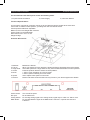
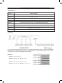
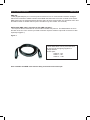
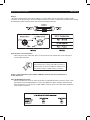
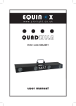
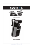
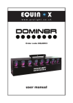
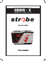
www.prolight.co.uk
Order code: STRO07
User manual
Equinox Strobe Command
Safety
WARNING
FOR YOUR OWN SAFETY, PLEASE READ THIS USER MANUAL CAREFULLY
BEFORE YOUR INITIAL START-UP!
CAUTION!
Keep this equipment away from rain,
moisture and liquids.
SAFETY INSTRUCTIONS
Every person involved with the installation, operation & maintenance of this
equipment should:
-
Be competent
-
Follow the instructions of this manual
CAUTION! TAKE CARE USING THIS EQUIPMENT!
HIGH VOLTAGE-RISK OF ELECTRIC SHOCK!!
Before your initial start-up, please make sure that there is no damage caused during
transportation. Should there be any, consult your dealer and do not use the
equipment.
To maintain the equipment in good working condition and to ensure safe operation, it is necessary
for the user to follow the safety instructions and warning notes written in this manual.
Please note that damages caused by user modifications to this equipment are not
subject to warranty.
Equinox Strobe Command
Safety
IMPORTANT:
The manufacturer will not accept liability for any resulting damages caused
by the non-observance of this manual or any unauthorised modification to the
equipment.
• Never let the power-cable come into contact with other cables. Handle the power-cable
and all mains voltage connections with particular caution!
• Never remove warning or informative labels from the equipment.
• Do not open the equipment and do not modify the equipment.
• Do not connect this equipment to a dimmer-pack.
• Do not switch the equipment on and off in short intervals, as this will reduce the
system’s life.
• Only use the equipment indoors.
• Do not expose to flammable sources, liquids or gases.
• Always disconnect the power from the mains when equipment is not in use or before
cleaning! Only handle the power-cable by the plug. Never pull out the plug by pulling the
power-cable.
• Make sure that the available voltage is between 220v/240v.
• Make sure that the power-cable is never crimped or damaged. Check the equipment and
the power-cable periodically.
• If the equipment is dropped or damaged, disconnect the mains power supply immediately.
Have a qualified engineer inspect the equipment before operating again.
• If the equipment has been exposed to drastic temperature fluctuation (e.g. after
transportation), do not switch it on immediately. The arising condensation might damage
the equipment. Leave the equipment switched off until it has reached room temperature.
• If your product fails to function correctly, discontinue use immediately. Pack the unit
securely (preferably in the original packing material), and return it to your Prolight dealer
for service.
• Only use fuses of same type and rating.
• Repairs, servicing and power connection must only be carried out by a qualified
technician. THIS UNIT CONTAINS NO USER SERVICEABLE PARTS.
• WARRANTY; One year from date of purchase.
OPERATING DETERMINATIONS
If this equipment is operated in any other way, than those described in this manual,
the product may suffer damage and the warranty becomes void.
Incorrect operation may lead to danger e.g.: short-circuit, burns, electric shocks,
lamp failure etc.
Do not endanger your own safety and the safety of others!
Incorrect installation or use can cause serious damage to people and property.
Equinox Strobe Command
Technical specifications
You should find inside the Equinox carton the following items:
1, Equinox Strobe Command
Technical Specifications:
2, Power Supply
3, Instruction Manual
An innovative, user friendly controller controls up to four DMX and analog strobes at the same time.
Comes with 10 different chase patterns, providing both Auto and Sound modes.
Chase Speed and Dimmer adjustable.
Blackout, Full on and Single flash functions.
Power supply: DC 9V 500mA Min.
Dimensions: 210 x 133 x 77 mm
Weight: 0.8Kgs
Overview & Functions
1. Blackout:
2. Full On:
3. Single flash:
4. Chase:
5. Mode:
6. Speed:
7. Dimmer:
Power Switch:
DC Input:
Analog Strobe:
DMX Strobe:
Blackout the fixtures.
When you press the Full On button the strobe will flash at full brightness and fast speed.
This button produces a single flash but only when the Blackout button has been pressed.
Press the up/down button to select 10 chase patterns.
1. LED in green indicating it’s in Sound mode.
2. LED in yellow indicating it’s in Auto mode.
Use to adjust chase speed in auto mode.
Please note that the Dimmer slider will only function if your strobe supports this feature.
Turn On/Off the power.
DC 9V 500mA min.
For sending analog signal to the analog strobe, signal output +12DC 1/4” Stereo Jack.
For sending DMX512 signal to the DMX strobe. Channel 1 is speed and channel 2
is dimmer.
Equinox Strobe Command
Overview
Chase Patterns
Pattern 0
Random pattern
Pattern 1
1234 Full on
Pattern 2
1-2-3-4 ― 4-3-2-1
Pattern 3
1-2-3-4-3-2-1
Pattern 4
12-34 ― 24-13 ― 23-14
Pattern 5
1-12-123-1234-123-12-1-stop ―4-43-432-4321-432-43-4-stop
Pattern 6
1-12-123-1234-234-34-4-stop―4-43-432-4321-321-21-1-stop
Pattern 7
1-3-2-4-3-1-4-2
Pattern 8
12-23-34-41 ― 43-32-21-14
Pattern 9
12-123-12-1234―43-432-43-4321
Connection
If you use the Strobe Command to control 4 x 2 channels DMX strobes, firstly you have to set the DMX
addresses of the strobes (a sample of how to set DMX address by dip switches is given below) so that
every strobe can receive its signal and work correctly.
Examples:
Channel 1 : dip / on : #1 ( 1 )
Channel 3 : dip / on : #1, #2 ( 1 + 2 = 3)
Channel 5 : dip / on : #1, #3 ( 1 + 4 = 5 )
Channel 7 : dip / on : #1, #2, #3 ( 1 + 2 + 4 = 7 )
Equinox Strobe Command
DMX Set up
DMX-512:
• DMX (Digital Multiplex) is a universal protocol used as a form of communication between intelligent
fixtures and controllers. A DMX controller sends DMX data instructions form the controller to the fixture.
DMX data is sent as serial data that travels from fixture to fixture via the DATA “IN” and DATA “OUT” XLR
terminals located on all DMX fixtures (most controllers only have a data “out” terminal).
DATA Cable (DMX cable) requirements (for DMX operation):
• The Equinox Strobe Command can be controlled via DMX-512 protocol. The DMX address is set on
the back of the unit. Your unit and your DMX controller require a standard 3-pin XLR connector for data
input/output (figure 1).
Figure 1
Further DMX cables can be purchased from
all good sound and lighting suppliers or
Prolight dealers.
Please quote:
CABL10 – 2M
CABL11 – 5M
CABL12 – 10M
Also remember that DMX cable must be daisy chained and cannot be split.
Equinox Strobe Command
DMX Set up
Notice:
• Be sure to follow figures 2 & 3 when making your own cables. Do not connect the cable’s shield
conductor to the ground lug or allow the shield conductor to come in contact with the XLR’s outer casing.
Grounding the shield could cause a short circuit and erratic behaviour.
Special Note: Line termination:
• When longer runs of cable are used, you may need to use a terminator on the last unit to
avoid erratic behaviour.
Termination reduces signal transmission problems
and interferance. it is always advisable to connect a
DMX terminal, (resistance 120 Ohm 1/4 W) between
pin 2 (DMX-) and pin 3 (DMX+) of the last fixture.
Using a cable terminator (part number CABL90) will decrease the possibilities of
erratic behaviour.
5-Pin XLR DMX Connectors:
• Some manufactures use 5-pin XLR connectors for data transmission in place of 3-pin. 5-Pin
XLR fixtures may be implemented in a 3-pin XLR DMX line. When inserting standard 5-pin
XLR connectors in to a 3-pin line a cable adaptor must be used. The Chart below details the
correct cable conversion.