1
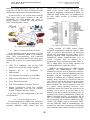
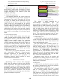
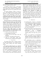
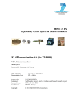
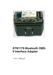
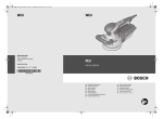
Iraq J. Electrical and Electronic Engineering Vol.10 No.2 , 2014 اﻟﻤﺠﻠﺔ اﻟﻌﺮاﻗﻴﺔ ﻟﻠﻬﻨﺪﺳﺔ اﻟﻜﻬﺮﺑﺎﺋﻴﺔ واﻻﻟﻜﺘﺮوﻧﻴﺔ 2014 ، 2 اﻟﻌﺪد، 10 ﻡﺠﻠﺪ Vehicle Remote Support and Surveillance System Ahmed J. Abid Electronic Eng. Dept., Foundation of Technical Education, Baghdad, Iraq [email protected] Ramzy S. Ali Elec. Eng. Dept., Collage of Engineering, University of Basrah, Iraq [email protected] Rafah A. Saheb Electronic Eng. Dept., Foundation of Technical Education, Baghdad, Iraq Abstract—the proposed design offers a complete solution to support and surveillance vehicles remotely. The offered algorithm allows a monitoring center to track vehicles; diagnoses fault remotely, control the traffic and control CO emission. The system is programmed to scan the on-board diagnostic OBD periodically or based on request to check if there are any faults and read all the available sensors, then make an early fault prediction based on the sensor readings, an experience with the vehicle type and fault history. It is so useful for people who are not familiar with fault diagnosis as well as the maintenance center. The system offers tracking the vehicle remotely, which protects it against theft and warn the driver if it exceeds the speed limit according to its location. Finally, it allows the user to report any traffic congestion and allows a vehicle navigator to be up to date with the traffic condition based on the other system’s user feedback. Keywords; accident reporting; emissions-related diagnostics; fault remotely diagnostic; traffic control; vehicle tracking. I. The system uses the location data to warn the drivers about speed limit on the current location, the traffic condition and to find the nearest maintenance or rescue center in case of help required. INTRODUCTION The proposed design offers a complete electronic and communication solution to deal with the new vehicle generation and the difficulties that we face every day. The MC uses all the available data about vehicles location, speed, and the feedback from the other users system to translate these data into a useful traffic map which will use to update the vehicles’ navigator and traffic condition. The design presents a remote fault diagnosis, an OBDII to USB adaptor which is used to read all the fault codes, sensors readings and the Vehicle Identification Number (VIN). The used microcontroller (18F4550) is USB compatible, so it is read the OBD and forwards the data as required via GSM modem. This option will be useful for people who are not familiar with fault diagnosis. The maintenance center will receive a report from the MC about the vehicle status and if it can be maintained locally or if it needs to be loaded. One of the important issues of this research is the driver safety. The design takes into consideration most of the problems that could face the driver. The system is periodically checking the airbag sensor and informs the monitoring center (MC) if any accident happens. MC had used the GSM modem in the system to try calling the driver before sending help. The early report about any accident could save the driver’s life and save the rescue time since the system will report the accurate vehicle location. There are many researchers who adopted other useful strategies to scan On-Board Diagnostic (OBD) [1], [2] and [3], but OBD should scan when the vehicle stopped as recommended. Other researchers offer added extra sensors like seat belt, alcohol sensor and eye sensor [4] to make the driving is more safe. The VIN will be used for security reason, since every car has a unique number, so it will be easy to track any car based on its VIN or to identify the vehicle owner according to the central database. The system also presents a real time vehicle tracking that can locate the vehicle in case of stolen or help required. The tracking strategy is based on fetching the location, time, date and speed from the GPS card and forwarding them on the GSM card. Many researches discussed localization of the vehicle based on GPS, GSM and GIS units [5], [6], [7] and [8]. Environmentally, the system reads periodically the oxygen sensor and warns the driver until specific level, but if the level exceeds then alarm the MC. One of the standardization of the 55 Iraq J. Electrical and Electronic Engineering Vol.10 No.2 , 2014 اﻟﻤﺠﻠﺔ اﻟﻌﺮاﻗﻴﺔ ﻟﻠﻬﻨﺪﺳﺔ اﻟﻜﻬﺮﺑﺎﺋﻴﺔ واﻻﻟﻜﺘﺮوﻧﻴﺔ 2014 ، 2 اﻟﻌﺪد، 10 ﻡﺠﻠﺪ emissions-related diagnostic services and the oxygen level is BS ISO 15031-5:2006 by ISO (the International Organization for Standardization). vehicle owner or repair technician access to the status of the various vehicle sub-systems. The amount of diagnostic information available via OBD has varied widely since its introduction in the early 1980s' versions of on-board vehicle computers. As shown in Fig. 1, the vehicle always read the GPS signal and reports location to the MC periodically via GSM modem. MC center is already having a secured line with the rescue office and maintenance center. Fig. 2 Microcontroller Pins Configurations Fig. 1 Signal propagation diagram II. Early versions of OBD would simply illuminate a malfunction indicator light or "idiot light" if a problem was detected, but would not provide any information as to the nature of the problem. Modern OBD implementations use a standardized digital communications port to provide real-time data in addition to a standardized series of diagnostic trouble codes, or DTCs, which allow one to rapidly identify and remedy malfunctions within the vehicle. MICROCONTROLLER BASED SYSTEM As an embedded system, this system is used an 18F4550 microcontroller which is an enhanced flash, USB microcontrollers with nanoWatt technology. This microcontroller has many good features that required for system implementation, like: USB V2.0 compliant with on-chip USB transceiver with on-chip voltage regulator Supports up bidirectional). Two External Clock modes, up to 48 MHz. High-Current Sink/Source: 25 mA/25 mA. Three External Interrupts. Four Timer modules (Timer0 to Timer3). Master Synchronous Serial Port (MSSP) module supporting 3-wire SPI (all 4 modes) and I2C™ Master and Slave modes to 32 Endpoints OBD-II is an improvement over OBD-I in both capability and standardization. The OBD-II standard specifies the type of diagnostic connector and its pin out, the electrical signalling protocols available, and the messaging format. It also provides a candidate list of vehicle parameters to monitor along with how to encode the data for each. There is a pin in the connector that provides power for the scan tool from the vehicle battery, which eliminates the need to connect a scan tool to a power source separately. However, some technicians might still connect the scan tool to an auxiliary power source to protect data in the unusual event that a vehicle experiences a loss of electrical power due to a malfunction. Finally, the OBD-II standard provides an extensible list of DTCs. As a result of this standardization, a single device can query the on-board computer(s) in any vehicle. This OBD-II came in two models OBDIIA and OBD-IIB. OBD-II standardization was prompted by emissions requirements, and though only emission-related codes and data are required (16 Fig.2 shows the pins configuration of the used microcontroller. III. ON-BOARD DIAGNOSTICS On-board diagnostics (OBD) is an automotive term referring to a vehicle's self-diagnostic and reporting capability. OBD systems give the 56 Iraq J. Electrical and Electronic Engineering Vol.10 No.2 , 2014 اﻟﻤﺠﻠﺔ اﻟﻌﺮاﻗﻴﺔ ﻟﻠﻬﻨﺪﺳﺔ اﻟﻜﻬﺮﺑﺎﺋﻴﺔ واﻻﻟﻜﺘﺮوﻧﻴﺔ 2014 ، 2 اﻟﻌﺪد، 10 ﻡﺠﻠﺪ to be transmitted through it, most manufacturers have made the OBD-II Data Link Connector the only one in the vehicle through which all systems are diagnosed and programmed. OBD-II Diagnostic Trouble Codes are 4-digit, preceded by a letter: P for engine and transmission (Powertrain), B for body, C for the chassis, and U for the network. Fig. 3 shows the pin configuration of OBD connector and Table. I is the description of these pins. IV. SYSTEM FEATURES The system has many combined features that make the driving safer, maintenance faster, avoid stealing of a vehicle, and eases the reaching of the destination which will save fuel and time. Fig. 4 briefly shows these features. Early Warning Remote Fault Diagnosis Vehicle Tracking Traffic Control Safety vehicle ID verification Environme nt friendly Fig. 3 OBD Connector Shape Fig. 4. System Features For example, if the vehicle has pin numbers 2, 4, 5, 10, and 14 populated, then the vehicle will be using the SAE-J1850 protocol (and this vehicle was made by Ford). Early Warning The system has the ability to display and send an early warning message to the driver and the monitoring center. According to the sensor’s measurement some faults can be predicted by the system based on car history and experience data base. A. As a ―rule of thumb‖, Ford vehicles use the SAE-J1850 PWM protocol, Japanese vehicles use ISO 14230, Chrysler and other foreign vehicles use ISO 9141, and GM uses SAE-J1850 VPW. The exception to this are vehicles that are year 2005 (some not all vehicles 2005-2008) or newer (2008 and newer for certain as CAN bus was mandated in 2008) as these vehicles all use the CAN bus. However, even if a vehicle uses the CAN bus, there are multiple CAN bus protocols. To determine exactly which CAN bus protocol the STN1110 is using, you will have to rely on the software running on the master device reporting then protocol being used [9]. Vehicle Tracking The system uses a GPS card to find the vehicle’s location and speed. This information will be used by the system for tracking the vehicle for many reasons. The first is to track the vehicle in case the car got stolen and the second is to find the nearest maintenance center in case help was needed. B. Remote Fault Diagnosis Fault codes and sensor’s measurement are read as required by the system via the OBD connector. These codes and sensor readings are sent to the monitoring center if required to evaluate the vehicle status and make a decision if the vehicle can be fixed on location and what spare parts are required or if it needs to be loaded to the nearest maintenance center. C. Table I OBD-II Pin Configuration Pin Number 1 2 3 4 5 6 7 8 9 10 11 12 13 14 15 16 Function Single-Wire CAN, J2411 Bus + of SAE-J1850 PWM or VPW Not used on adapter Chassis Ground Signal Ground CAN High, ISO 15765-4, SAE-J2284 K-line of ISO 9141-2 and ISO 14230-4 Not Used Not Used Bus – of SAE-J1850 only Not used on adapter Not Used Not Used CAN Low, ISO 15765-4 and SAE-J2284 L-line of ISO 9141-2 and ISO 14230-4 Battery Positive Safety One of the most important sensors that need to be read periodically by the system is the airbag’s sensor. The system will send a high priority warning message to the monitoring center that includes the vehicle’s location if the vehicle’s airbag is activated. The monitoring center employer can use the system GSM modem to make a call to the driver and checks if the driver can answer or not before sending help. D. 57 Iraq J. Electrical and Electronic Engineering Vol.10 No.2 , 2014 Traffic control Monitoring center can avoid heavy traffic paths location. Monitoring center weight according to the update its traffic map. اﻟﻤﺠﻠﺔ اﻟﻌﺮاﻗﻴﺔ ﻟﻠﻬﻨﺪﺳﺔ اﻟﻜﻬﺮﺑﺎﺋﻴﺔ واﻻﻟﻜﺘﺮوﻧﻴﺔ 2014 ، 2 اﻟﻌﺪد، 10 ﻡﺠﻠﺪ E. advise the driver to according to his/her can predict the traffic vehicle’s speed and Vehicle ID verification VIN helpfully identifies the vehicle, since the VIN is a unique for every car and it specifies the fingerprint of the vehicle. Typically, the VIN can be found by looking at the dashboard near the windshield on the driver’s side of the vehicle (refer to the car’s user manual for the specific location). The system is designed to fetch the VIN from the OBD. By using the VIN, it is possible to remotely identify the vehicle owner at the checkpoint by the police who can easily identify the overspeed cars since the system can report the over speed car according to its location speed limit. Environment friendly In the United States, many states now use OBD-II testing instead of tailpipe testing in OBDII compliant vehicles (1996 and newer). Since OBD-II stores trouble codes for emissions equipment, the testing computer can query the vehicle's onboard computer and verify if there are no emission related trouble codes and that the vehicle is in compliance with emission standards for the model year it was manufactured. In the Netherlands, 2006 and later vehicles get a yearly EOBD emission check. ISO 15031 [10] specifies diagnostic services and functionally addressed request/response messages required to be supported by motor vehicles and external test equipment for diagnostic purposes which pertain to motor vehicle emission-related data. V. MONITORING CENTER Monitoring center receives short messages SMS from all registered vehicles with different levels of priorities. The system sends data to the monitoring system on different saved number according to its priority. Fig. 5 shows the levels of the priority as proposed by the design but priority levels are a matter of discussion. The received data classified at the monitoring center into three groups according to its priority. 58 • Safety • Remote Fault Diagnosis Medium Priority • Early Warning • Vehicle Tracking • Vehicle ID verification Low Priority F. G. High Priority • Traffic control • Environment Sensor Report Fig. 5 Levels of Priorities VI. SYSTEM ARCHITECTURE The system is totally managed by a microcontroller PIC18F4550 type. The microcontroller periodically reads the vehicle diagnosis data via OBD connector to predict any expected fault, but it sends a warning message only for high priority faults. It also specifies the vehicle’s location based on a GPS card. A 2x20 characters LCD has been used to display the fault or any other value need to be monitored by the driver. The system has separated cards for now, but it should compact to reduce its size and cost. GSM/GPRS Card A GSM/GPRS modem is used in this design as a wide coverage area transceiver. This modem is used to transmit and receive data between the system and monitoring center. A. The used modem called ―GSM2 Click™‖ by ―Microelectronica‖ has a Quectel M95 IC, it is ideal for mobile devices. The Quectel M95 is a quad-band GSM/GPRS engine that works at frequencies of GSM850MHz, GSM900MHz, DCS1800MHz or PCS1900MHz with 85.6 kbps GPRS data transfer. It supports internet service protocols, such as TCP/IP, UDP, FTP and PPP. Fig. 6 shows the GSM/GPRS card. Monitoring center will use the speaker and microphone for calling purpose to check if the driver is conscious at emergency cases, ex: if the airbag sensor is activated. GPS card A GPS card is used by the system to specify the vehicle’s location to be sent by the system to the monitoring center as required. B. The used modem called ―GPS Click‖, a board with its LEA-6S module features acquisition down to 1s, –147dBm cold start sensitivity and 5Hz update rate, low power consumption due to intelligent, user configurable power management. Mentioned features make this board ideal for asset Iraq J. Electrical and Electronic Engineering Vol.10 No.2 , 2014 اﻟﻤﺠﻠﺔ اﻟﻌﺮاﻗﻴﺔ ﻟﻠﻬﻨﺪﺳﺔ اﻟﻜﻬﺮﺑﺎﺋﻴﺔ واﻻﻟﻜﺘﺮوﻧﻴﺔ 2014 ، 2 اﻟﻌﺪد، 10 ﻡﺠﻠﺪ tracking, road navigation devices, public transportation vehicle information systems and more. Fig. 7 shows the GPS card. The extent that a PC tool may access manufacturer or vehicle-specific ECU diagnostics varies between software products as it does between handheld scanners. Fig. 8 shows the OBD to USB adaptor. Fig. 8. Typical simple USB KKL Diagnostic Interface Fig. 6. GSM/GPRS Cards MicroSD RAM The system uses a MicroSD RAM to save all GPS and sensor readings by fetching them periodically. The saved data is optional, but it may include the following: D. The GPS data (longitude and latitude with timestamp) will be saved periodically for the last month, for example; these data will be used to plot the vehicle path on the Google map if required. Fault codes will be saved directly with time stamp too; these codes will serve to study the fault history by the maintenance center. Fig. 7. GPS card MCU-based Scan Tools and Analysis Platforms A PC or MCU based OBD analysis tool converts the OBD-II signals to serial data (USB or serial port) standard for PCs or MCU. The software then decodes the received data to a visual display. Many popular interfaces are based on the ELM or STN1110 which is considered as the world’s smallest, lowest cost multiprotocol OBD to UART interpreter IC [11] and [12], both of which read all five generic OBD-II protocols. Some adapters now use the J2534 API allowing them to access OBD-II Protocols for both cars and trucks. C. In addition to the functions of a handheld scan tool, the PC-based tools generally offer: Large storage capacity for data logging and other functions. Higher resolution screen than handheld tools. The ability to use multiple software programs, adding flexibility. 59 Fig. 9 shows the used MicroSD. Once the power is turned on, the power LED will indicate that the board is in operation. Data is read and written to the card using the industry standard SPI interface. VII. SYSTEM INTERNAL NETWORK Microcontroller is managing all the tools to complete the job. It receives the GPS data (GPRMC recommended minimum data) via RS232 @9600 bps. At the same bitrate the microcontroller communicates with the GSM / GPRS card via soft RS232 and based on AT commands. OBD-II scanner communicate with the microcontroller via USB, it scans the vehicle sensors based on the MCU request. Iraq J. Electrical and Electronic Engineering Vol.10 No.2 , 2014 اﻟﻤﺠﻠﺔ اﻟﻌﺮاﻗﻴﺔ ﻟﻠﻬﻨﺪﺳﺔ اﻟﻜﻬﺮﺑﺎﺋﻴﺔ واﻻﻟﻜﺘﺮوﻧﻴﺔ 2014 ، 2 اﻟﻌﺪد، 10 ﻡﺠﻠﺪ The system checks periodically if there is any request to scan the OBD-II for diagnostics, if any, the system will check if the vehicle stops. This can be checked easily using the vehicle gear status or any other indication, then scan and diagnose the faults if any. The result will time stamp and save on the MicroSD card. After that the system will make a decision if there is any predicted fault or existence fault and what level of priority, then classify them according to their priority. Low level faults displays a warning message on the LCD screen, the high level fault is sent directly to the monitoring center as an alarm message. For the vehicle tracking purpose, the microcontroller is interrupted by any incoming message. When the system receives a message and after checking the sender ID, it will replay a message with the required data. There are three types of incoming messages to the system from three different senders: Monitoring center, police and the vehicle’s owner. Fig. 9. Micro-SD Card The system backup the data about the location and the fault history on MicroSD card via SPI (Serial Peripheral Interface Bus) bus. Fig. 10 shows the signal line diagram of the system. Speaker and Microphone GSM/ GPRS Modem RS232 GPS Modem RS232 OBD Scanner USB Micro SD RAM PIC18F4550 Microcontroller The first is the request to diagnose, this type of message is incoming from the monitoring center or the vehicle owner to diagnose the vehicle. The second is the request for tracking, this type of message can only be sent by the police for safety reasons. The third is the request to update the navigational data about the traffic, this message is sent by the monitoring center. Monitoring center can predict the traffic based on the vehicles’ speed and location which is based on the feedback from the users of the designed system. System users can easily report the heavy traffic by one push button. SPI LCD Screen Fig. 10. System Block Diagram VIII. SOFTWARE FLOWCHART The main part of the design is the microcontroller which manages the entire cards, according to the flowchart shown in the Fig. 11. Environment is a very important issue, the deigned system offers to read the oxygen sensor and checks if the reading exceeds the threshold value to warn the user or send a report to the monitoring center. The microcontroller is programmed to gather the data periodically from the GPS. These data will save to MicroSD RAM to plot the vehicle path as required. It also can be sent to the monitoring center in case of emergency or to the police in case the vehicle is stolen. IX. RESULT AND DISCUTION The system is designed for specific type of vehicle in matter of software and hardware to decrease its cost and complexity add for that it will be fixed in vehicle and not portable but it could be any type of vehicle. Because of the increased of the vehicle over speed accidents, the system adopts a strategy to monitor the over speed of the vehicle according to its location and the navigator speed map. If the driver crosses the speed limit, the system warns him/her, but if the speed keeps increasing, an alarm message will be sent to the monitoring center to report the driver speed, location and vehicle verification number. The microcontroller has been programmed using Flowcode V4 for PICmicros which is one of the most advanced graphical programming languages for microcontrollers. The system has 60 Iraq J. Electrical and Electronic Engineering Vol.10 No.2 , 2014 اﻟﻤﺠﻠﺔ اﻟﻌﺮاﻗﻴﺔ ﻟﻠﻬﻨﺪﺳﺔ اﻟﻜﻬﺮﺑﺎﺋﻴﺔ واﻻﻟﻜﺘﺮوﻧﻴﺔ 2014 ، 2 اﻟﻌﺪد، 10 ﻡﺠﻠﺪ been simulated by using the mentioned software and some snapshots had been taken. like RS232, SPI (Serial Peripheral Interface) and USB. All the difficulties that face the police, drivers and the environment have been taken into consideration for safer driving, fast rescue response and a better environment. The design has a limitation that its reporting efficiency based on the GSM coverage area, and to increase its efficiency, it is required to design an independence RF transceiver or to add a GSM booster. The system will provide an accurate data in a timely manner such that it will enable the police to know the location of the tracked vehicle. It’s also served the maintenance center for fast response when help is required for the system reports the exact location of the vehicle and a brief fault diagnosis data. A snapshot is shown in Fig. 12; this photo shows the vehicle location information. Latitude (LT) is shown in the second line, Longitude (LG) on the third and speed over ground (SG) on the fourth. The system diagnostic window is shown in Fig.13. This snapshot shows the system is healthy and there is no fault. In the third and fourth lines there are some instructions to the user for example; press UP to scan OBD, Left (LT) switch to report the vehicle status to the control center, Right (RT) switch to back to the previous window and down (DN) for more information about the sensor reading. XI. Warning messages are automatically generated by the system. Fig. 14 shows one of these warning messages ―Misfire detected with low fuel‖ by using a force code for testing purpose. This message can be skipped by pressing OK key but alarms messages displayed with report option in case if the owner need to request help from the monitoring center. The system hardware has been simulated using Protues7.10 as shown in Fig. 15. The Fig. shows OBD adaptor too, which consisting of OBD to RS232 then RS232 to USB. Note it is possible to use RS232 directly for the microcontrollers that not support USB. [1] Ying-Shing Shiao, Chih-Chi Li, Sung-Huan Yang, Shun-Hua Lin, and Chun-Yi Lin Chin E. Lin, "Real-Time Remote Onboard Diagnostics Using Embedded GPRS Surveillance Technology," IEEE TRANSACTIONS ON VEHICULAR TECHNOLOGY, vol. 56, no. 3, pp. 1108-1118, May 2007. [2] Wang Quanqi, Wang Jian, and Wang Yanyan, "Design of vehicle bus data acquisition and fault diagnosis system," in International conference on Consumer Electronics,Communications and Networks, Xianning, China, 16-18 April 2011, pp. 245248. [3] Chin E. Lin, Chih-Chi Li, and Sung-Huan Yang, "Development of On-Line Diagnostics and Real Time Early Warning System for Vehicles," in Sensors for Industry Conference, Houston, Texas, USA, 8-10 Feb. 2005, pp. 4551. [4] R. Rathinakumar and D. Manivannan, "Wireless Accident Information System Using GSM and GPS," Research Journal of Applied Sciences, Engineering and Technology, vol. 4, no. 18, pp. 3323-3326, Sep. 2012. [5] Dada O. A., Akinwonmi F. C. Kuboye B. M., "GSM Base Stations Location Monitoring using Geographic Information System," International Journal of Computer Network and Information Security(IJCNIS), vol. 5, no. 8, pp. 39-45, June 2013. [6] Kunal Maurya , Mandeep Singh , and Neelu Jain, "Real Time Vehicle Tracking System using GSM and GPS Technology- An Anti- LCD screen used in 4 bits mode. Programmable 6 pin socket. Sockets for the used GSM, GPS and MicroSD. UP, Down, Left, Right and OK switches. LEDs for GPS Ready, GSM ready, MicroSD ready, warning and alarm signals. X. REFRENCES CONCLUSION The design system offers a complete solution for online fault diagnosis, early warning system, traffic control strategy and vehicle tracking system. The system is based for now on a separated GPS, GSM, MicroSD and OBD scanner, but it is required to make a compact electronic card which can be smaller in size and have low cost. For now the system is simulated in Proteus 8 as shown in Fig. 15. The PIC18F4550 microcontroller is the brain of this circuit; it communicates with the entire peripherals cards with at different protocols 61 Iraq J. Electrical and Electronic Engineering Vol.10 No.2 , 2014 اﻟﻤﺠﻠﺔ اﻟﻌﺮاﻗﻴﺔ ﻟﻠﻬﻨﺪﺳﺔ اﻟﻜﻬﺮﺑﺎﺋﻴﺔ واﻻﻟﻜﺘﺮوﻧﻴﺔ 2014 ، 2 اﻟﻌﺪد، 10 ﻡﺠﻠﺪ theft Tracking System," International Journal of Electronics and Computer Science Engineering, vol. 1, no. 3, pp. 1103-107, Aug. 2012. [7] khan Abid and Mishra Ravi , "GPS – GSM Based Tracking System," International Journal of Engineering Trends and Technology, vol. 3, no. 2, pp. 161-164, 2012. [8] Francis Enejo Idachaba, "Design of a GPS/GSM Based Tracker for the Location of Stolen Items and Kidnapped or Missing Persons in Nigeria," ARPN Journal of Engineering and Applied Sciences, vol. 6, no. 10, pp. 56-60, OCT. 2011. [9] "Bluetooth OBD-II Interface Adapter," http://ahdesign.us/blog/obdii/Bluetooth_OBDII _Manual.pdf,. [10] "Road vehicles —Communication between vehicle and external equipment for emissionsrelated diagnostics," British standard, BSI Standards BS ISO 15031-5:2006,. [11] "STN1110 specifications ," http://www.obdsol.com/stn1110/,. [12] Hu Jie, Yan Fuwu, Tian Jing, Wang Pan, and Cao Kai, "Developing PC-Based Automobile Diagnostic System Based on OBD System," in Power and Energy Engineering Conference (APPEEC), Asia-Pacific, 28-31 March 2010, pp. 1-5. Start Read GPS data include Location, Date and Time. Save Data to the SD-RAM Report the current Speed, location and VIN YES Check if vehicle cross the area speed limit No Check request to diagnosis and vehicle stop No Yes Scan OBD-II diagnostic data. Save Data to the SD-RAM Make decision if there is any predicted fault or exist fault and what level of priority. Warning Alarm Is there any warning or alarm Display warning message on the LCD Screen Send Data to the monitoring center by GSM Read GSM messages Send Vehicle location and speed to the monitoring center by GSM Yes Request for Track? No Report the Monitoring Center Yes Check CO2 sensor? No Update navigator map Yes Is there any traffic info.? No Send report to the monitoring center by GSM Yes Report a heavy traffic No END Fig. 11. Software Flowchart 62 Iraq J. Electrical and Electronic Engineering Vol.10 No.2 , 2014 اﻟﻤﺠﻠﺔ اﻟﻌﺮاﻗﻴﺔ ﻟﻠﻬﻨﺪﺳﺔ اﻟﻜﻬﺮﺑﺎﺋﻴﺔ واﻻﻟﻜﺘﺮوﻧﻴﺔ 2014 ، 2 اﻟﻌﺪد، 10 ﻡﺠﻠﺪ Fig. 12 Vehicle’s location simulation Fig. 14 An example to warning message Fig. 13 Fault diagnosis simulation Fig. 15 System hardware simulation 63