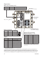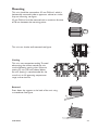
1
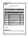
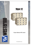
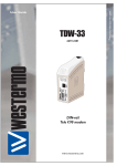
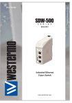
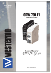
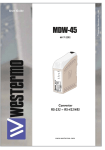
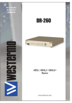
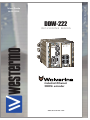
6642-22203
DDW-222
W o lv e r i n e s e r i e s
RX
TX
2
1
DSL
DDW-222
Industrial Ethernet
SHDSL extender
www.westermo.com
© Westermo Teleindustri AB
User Guide
Legal information
The contents of this document are provided “as is”. Except as required by applicable
law, no warranties of any kind, either express or implied, including, but not limited to,
the implied warranties of merchantability and fitness for a particular purpose, are made
in relation to the accuracy and reliability or contents of this document. Westermo
reserves the right to revise this document or withdraw it at any time without prior
notice.
Under no circumstances shall Westermo be responsible for any loss of data or income
or any special, incidental, and consequential or indirect damages howsoever caused.
More information about Westermo can be found at the following Internet address:
http://www.westermo.com
2
6642-22203
Safety
!
Before installation:
Read this manual completely and gather all information on the unit. Make sure that
you understand it fully. Check that your application does not exceed the safe operating specifications for this unit.
This unit should only be installed by qualified personnel.
This unit should be built-in to an apparatus cabinet, or similar, where access is
restricted to service personnel only.
The power supply wiring must be sufficiently fused, and if necessary it must be
possible to disconnect manually from the power supply. Ensure compliance to
national installation regulations.
This unit uses convection cooling. To avoid obstructing the airflow around the unit,
follow the spacing recommendations (see Cooling section).
!
Before mounting, using or removing this unit:
Prevent access to hazardous voltage by disconnecting the unit from power supply.
Warning! Do not open connected unit. Hazardous voltage may occur within this
unit when connected to power supply.
Care recommendations
Follow the care recommendations below to maintain full operation of unit and to fulfil
the warranty obligations.
This unit must not be operating with removed covers or lids.
Do not attempt to disassemble the unit. There are no user serviceable parts inside.
Do not drop, knock or shake the unit, rough handling above the specification may cause
damage to internal circuit boards.
Do not use harsh chemicals, cleaning solvents or strong detergents to clean the unit.
Do not paint the unit. Paint can clog the unit and prevent proper operation.
Do not expose the unit to any kind of liquids (rain, beverages, etc). The unit is not waterproof. Keep the unit within the specified humidity levels.
Do not use or store the unit in dusty, dirty areas, connectors as well as other mechanical
part may be damaged.
If the unit is not working properly, contact the place of purchase, nearest Westermo distributor office or Westermo Tech support.
A readily accessible disconnect device shall be incorporated external to the equipment.
This unit may have hot surfaces when used in high ambient temperature.
6642-22203
3
WARNING – SUBSTITUTION OF COMPONENTS MAY IMPAIR SUITABILITY FOR
DIVISION 2.
WARNING – DO NOT OPEN WHEN ENERGIZED.
WARNING – DO NOT DISCONNECT EQUIPMENT UNLESS AREA IS KNOWN TO
BE NON-HAZARDOUS.
AVERTISSEMENT – RISQUE D'EXPLOSION. NE PAS DÉBRANCHER TANT QUE LE
CIRCUIT EAT SOUS TENSION, Á MOINS QU'IL NE S'AGISSE
D'UN EMPLACEMENT NON DANGEREUX.
SPECIAL CONDITION OF USE:
This equipment shall be installed in compliance with the enclosure, mounting, spacing, and
segregation requirements of the ultimate application, including a tool removable cover.
Maintenance
No maintenance is required, as long as the unit is used as intended within the specified
conditions.
4
6642-22203
ATEX Information
General
This unit is intended to be used in Zone 2 hazardous location only.
Marking
II 3G
Ex nA IIC T4 Gc
SPECIAL CONDITION
WARNING – DO NOT SEPARATE WHEN ENERGIZED
Indicate that this unit complies with relevant European standards that are
harmonised with the 94/9/EC Directive (ATEX).
Equipment group II.
This unit can be installed in all places with an explosive gas atmosphere other
than mines susceptible to firedamp.
Equipment category 3.
A category is the classification according to the required level of protection.
This unit ensures the requisite level of protection during normal operation and
3
is intended for use in areas in which explosive atmosphere caused by gases,
vapours, mists, or dust mixtures are unlikely to occure or, if they do occure, are
likely to do so only infrequently and for a short periode only.
Indicates protection concerning explosive atmospheres caused by gases, vapours
G
or mists (G).
Ex
Indicates that this unit is in conformity with relevant European Ex standard(s).
The type of protection used.
This unit is a non-sparking device "nA" which is constructed to minimize the
nA
risk of occurence of arcs or sparks capable of creating an ignition hazard during
conditions of normal operation.
IIC
Gas group, a typical gas i hydrogen.
Temperature class T4 (T4 = 135°C).
T4
This unit is classified in accordance with its maximum surface temperature
(external and internal).
Equipment protection level Gc (EPL Gc)
Equipment for explosive gas atmospheres, having a "enhanced" level of protection, which is not a source of ignition in normal operation and which may have
Gc
some additional protection to ensure that it remains inactive as an ignition
source in the case of regular expected occurences.
EPL Gc are analogous to the ATEX Categories (Category 3 G = EPL Gc).
This unit has a special condition for safe use.
SPECIAL
The special condition for safe use contains safety related information that is
CONDITION
necesarry for the correct installation and safe use.
II
6642-22203
5
Special condition for use
Ambient temperature:
This unit is designed for use in extreme ambient temperature conditions according to the
following: –40 ºC ≤ Tamb ≤ +70 ºC
Installation in an apparatus cabinet:
This unit requires installation in an Ex certified apparatus cabinet suitable for the area of
use and providing a degree of protection of at least IP54.
Resistance to impact:
This unit requires installation in an apparatus cabinet where adequate resistance to
impact is provided by the apparatus cabinet.
See "Installation in an apparatus cabinet" above for requirements on the external
apparatus cabinet.
Resistance to light:
This unit requires installation in an apparatus cabinet where it is protected from light
(for example daylight or light from luminaires).
See "Installation in an apparatus cabinet" above for requirements on the external
apparatus cabinet.
Transient protection:
This unit requires external transient protection at the power supply terminals to be set
at a level not exceeding 67 VDC.
Secureness of plugs:
When this unit is installed in an explosive atmospheres, all connectors must be
mechanically secured to prevent loosening.
Conductor temperature:
When this unit is installed in locations with high ambient temperature, special precautions
shall be taken upon the choice of external conductor(s) and the temperature rating of
the conductor(s).
Directive 94/9/EC alongside with other directives:
Directive 2004/108/EC (EMC) applies and to assure a safe performance of this unit under
the scope of Directive 94/9/EC, refer to the electromagnetic immunity level specified
under "Type tests and environmental conditions" in this manual.
Warning marking:
When this unit is installed in an explosive atmospheres, the warning label submitted
together with this unit shall be attached on the unit and visible to the end user.
Standards and date of compliance
EN 60079-0 and EN 60079-15
2011-03-24
6
6642-22203
Ratings
Power
(20 – 48) VDC; 300 mA
Ambient temperature
–40ºC ≤ Ta ≤ +70ºC
Ingress protection (IP)
IP40
Maximum surface temperature
135ºC (temperatur class T4)
Safety Control Drawing
Degree of protection
Ambient temperature
Installation spacing
IP40
–40°C to +70°C
Minimum 25 mm above / below
Minimum 10 mm left / right
Direction relative this unit!
Pos.
1
2
3
4
5
6
7
8
9
Direction/
descripton
Not connected (DCD)
In/Received Data (RD)
Out/Transmitted Data (TD)
Out/Data Terminal Ready (DTR)
–/Signal Ground (SG)
In/Data Set Ready (DSR)
Out/Request To Send (RTS)
In/Clear To Send (CTS)
Not connected (RI)
Input/Output
values
Umax = ± 12 Vpk
Imax = ± 60 mA
Data rate:
0.3 – 115.2 kbit/s
Position
1
2
Direction*/
descripton
Input/Output
values
In/Out / SHDSL U = ± 5 Vpk
I = ± 25 mA
Data rate up to
In/Out / SHDSL 15.3 Mbit/s
* Galvanically isolated via signal transformer and
capacitively isolated to signal ground through a
1.5 kV 220 pF capacitor.
See user manual for proven transient protection.
Position
1
2
3
4
5
6
7
8
Direction*/
descripton
In/Out / TD+
In/Out / TD–
In/Out / RD+
Not connected
Not connected
In/Out / RD–
Not connected
Not connected
Input/Output
values
U = ± 1 V (4μV/s)
I = ± 20 mA
Data rate:
10/100 Mbit/s
* Galvanically isolated via signal transformers and
capacitively isolated to signal ground through a
2 kV 1000 pF capacitor.
See user manual for proven transient protection.
M5 threaded hole
for PE connection.
Position
Direction*/
descripton
1
In / +Voltage A
2
3
4
Input values
Uin = (10 – 60) VDC
In / +Voltage B
Iin = 420mA @ 16VDC
In / Common
PIn = Max 7 W
In / Common
* See section Type tests and environmental conditions in this user
manual for proven transient protection.
6642-22203
7
Agency approvals and standards compliance
Type
EMC
Safety
SHDSL
Ex
Approved
Agency/ W-mo
W-mo
W-mo
W-mo
W-mo
W-mo
W-mo
NEMKO
FM Approvals
W-mo
FCC Part 15.105 Notice:
Approval / Compliance
EN 61000-6-2, Immunity industrial environments
EN 55024, Immunity IT equipment
EN 61000-6-4, Emission industrial environments
FCC part 15 Class A
EN 50121-4, Railway signalling and telecommunications
apparatus
EN 60950-1, IT equipment
ITU-T G.991.2
Class I, Division 2
EN 60079-0 and EN 60079-15
This equipment has been tested and found to comply with the limits
for a Class A digital device, pursuant to Part 15 of the FCC Rules.
These limits are designed to provide reasonable protection against
harmful interference when the equipment is operated in a commercial
environment. This equipment generates, uses, and can radiate radio
frequency energy and, if not installed and used in accordance with the
instruction manual, may cause harmful interference to radio communications. Operation of this equipment in a residential area is likely to cause
harmful interference in which case the user will be required to correct
the interference at his own expense.
Warning
This is a class A product. In a domestic environment this product may
cause radio interference in which case the user may be required to take
adequate measures.
8
6642-22203
Declaration of Conformity
Westermo Teleindustri AB
Declaration of conformity
The manufacturer
Westermo Teleindustri AB
SE-640 40 Stora Sundby, Sweden
Herewith declares that the product(s)
Type of product
Model
Art no
Industrial Ethernet SHDSL extender
Wolverine DDW-22x series
3642-0200, 3642-0220,
3642-0240, 3642-0250
is in conformity with the following EC directive(s).
No
Short name
2004/108/EC
94/9/EC
Electromagnetic Compatibility (EMC)
Equipment Explosive Atmospheres (ATEX)
References of standards applied for this EC declaration of conformity.
No
Title
Issue
EN 61000-6-1
Electromagnetic compatibility – Immunity for residential
environments
Electromagnetic compatibility – Immunity for industrial
environments
Electromagnetic compatibility – Emission for residential
environments
Electromagnetic compatibility – Emission for industrial
environments
Information technology equipment - Immunity
2007
EN 61000-6-2
EN 61000-6-3
1
EN 61000-6-4
EN 55024
EN 55022
EN 50121-4
EN 60079-0
EN 60079-15
Information technology equipment – Radio disturbance
characteristics – Limits and methods of measurement
Railway applications – Electromagnetic compatibility –
Emission and immunity of the signalling and
telecommunications apparatus
Explosive atmospheres
Equipment – General requirements
Electrical apparatus for explosive gas atmospheres –
Construction, test and marking of type of protection “n”
electrical apparatus
The last two digits of the year in which the CE marking was affixed:
2005
2007
2007
1998 + A1:2001
+ A2:2003
2006 + A1:2007
2006
2009
2005
11
Pierre Öberg
Technical Manager
25 March 2011
1
Only applicable for article no. 3642-0250.
Postadress/Postal address
Tel.
Telefax
Postgiro
Bankgiro
Org.nr/
Corp. identity number
Registered office
S-640 40 Stora Sundby
Sweden
016-428000
Int+46 16428000
016-428001
Int+46 16428001
52 72 79-4
5671-5550
556361-2604
Eskilstuna
6642-22203
9
Type tests and environmental conditions
Phenomena
ESD
Test
EN 61000-4-2
RF field AM modulated
IEC 61000-4-3
Fast transient
EN 61000-4-4
Surge
EN 61000-4-5
RF conducted
EN 61000-4-6
Power frequency magnetic field
Pulse magnetic field
Mains freq. 50 Hz
Mains freq. 50 Hz
Voltage dips and interruption
EN 61000-4-8
Signal ports
Power ports
Signal ports balanced
Power ports
Signal ports
Power ports
Enclosure
EN 61000-4-9
EN 61000-4-16
SS 436 15 03
EN 61000-4-29
Enclosure
Signal ports
Signal ports
DC power ports
Radiated
emission
EN 55022
Enclosure
Conducted emission
Dielectric strength
Temperature
Humidity
Altitude
Reliability prediction
(MTBF)
Vibration
Shock
Enclosure
Dimension W x H x D
Weight
Degree of protection
Cooling
Mounting
10
Description
Enclosure contact
Enclosure air
Enclosure
FCC part 15
EN 55022
EN 60950
DC power ports
Signal port to other
isolated ports
Power port to other isolated
ports
Operating
Storage & Transport
Maximum surface temperatur
Operating
Storage & Transport
Operating
MIL-HDBK- 217F Operating
IEC 60068-2-6
IEC 60068-2-27
UL 94
Operating
Operating
Aluminium/Zink
IEC 529
Enclosure
Test levels
± 6 kV
± 8 kV
20 V/m 80% AM (1 kHz), 80 – 1000 MHz
10 V/m 80% AM (1 kHz), 1400 – 2100 MHz
5 V/m 80% AM (1 kHz), 2100 – 2500 MHz
1 V/m 80% AM (1 kHz), 2500 – 2700 MHz
± 2 kV
± 2 kV
± 2 kV line to earth, ± 1 kV line to line
± 2 kV line to earth, ± 2 kV line to line
10 V 80% AM (1 kHz), 0.15 – 80 MHz
10 V 80% AM (1 kHz), 0.15 – 80 MHz
300 A/m
300 A/m
100 V 50 Hz line to earth
250 V 50 Hz line to line
10 & 100 ms, interruption
10 ms, 30% reduction
10 ms, 60% reduction
+20% above & –20% below rated voltage
Class A
Class A
Class B
1500 Vrms 50 Hz 1 min
1500 Vrms 50 Hz 1 min
-40 to +70ºC
-40 to +70ºC
135 ºC (temperatur class T4)
5 to 95% relative humidity
5 to 95% relative humidity
2 000 m / 70 kPa
700 000 hours @ 25°C
7.5 mm, 5 – 8 Hz 2 g, 8 – 500 Hz
15 g, 11 ms
Flammability class V-0
134 x 105 x 122 mm
1.5 kg
IP40
Convection
Horizontal on 35 mm DIN-rail
6642-22203
Description
The DDW-222 is an Industrial Ethernet SHDSL extender with support for redundancy.
The redundant protocol can be used ether on the SHDSL interface or on the built-in
Ethernet switch. Also included are a RS-232 serial adapter and a 10-port Virtual Com
re-director software. The protocols used for network communication is UDP or TCP.
This allows the serial interface to be setup as a TCP-server or -client as well as an UDP
unit. Our unique FRNT (Fast Recovery of Network Topology) technology is the fastest
protocol on the market to re-configure a network in the event of any failure of a link or
hardware. SHDSL represents the best of several symmetric DSL technologies. This unit
provides the ability to reuse existing twisted copper pair with data rates from 192 kbit/s
to 5.7 Mbit/s in both directions. The DDW-222 makes it possible to communicate over
10 km (6.2 miles) on twisted pair cable.
The DDW-222 is a bridge not router and so is simple to install. All configuration is done
using a web interface. The DIN rail mounted DDW-222 is designed for harsh environments and can be used in industrial and railway applications. It can be powered from two
separate supplies and handle an operating voltage range of 16 – 60 VDC.
…… RS-232 serial adapter
…… 10 port Virtual Com software
…… Redundant protocol (FRNT) on SHDSL or on the Ethernet switch
…… 192 kbit/s to 5.7 Mbit/s
…… Over 10 km (6.2 miles) on twisted pair
…… Daisy chain SHDSL applications
…… Wide temperature range (–40 to +70°C) (–40 to 158°F)
…… Total galvanic isolation & transient protection
…… Industrial and Rail EMC approvals
…… Redundant power and wide DC input range
…… Configuration using web interface
…… Integrated 4-port Ethernet switch with 10/100Base-T/TX
…… Auto MDI/MDI-X
…… Auto speed on SHDSL with reliable, normal or high-speed mode
…… Comprehensive statistics
• SHDSL • Ethernet
…… SNMP support
…… Extensive line protection with over-current / voltage suppression
Diagram showing speed versus distance
Speed bit/s
192000
1024000
1280000
2304000
3328000
4544000
5696000
6642-22203
DDW-222 @ 0.5 mm
Distance metre / miles
10000 / 6.21
7650 / 4.75
7050 / 4.38
5950 / 3.69
4900 / 3.04
4250 / 2.64
3650 / 2.26
DDW-222 @ 0.4 mm
Distance metre / miles
6450 / 4.00
4850 / 3.01
4700 / 2.92
4150 / 2.58
3700 / 2.30
3150 / 1.95
2800 / 1.73
11
Interface specifications
Power
Rated voltage
Operating voltage
Rated current
Rated frequency
Inrush current, I2t
Startup current*
Polarity
Redundant power input
Isolation to
Connection
Connector size
Shielded cable
20 to 48 VDC
16 to 60 VDC
300 mA @ 20 VDC
150 mA @ 48 VDC
DC
3.1 A2s
400 mA
Reverse polarity protected
Yes
Ethernet, SHDSL, RS-232
Detachable screw terminal
0.2 – 2.5 mm2 (AWG 24 – 12)
Not required
* If external power supply is used it must meet specified inrush current.
SHDSL
Electrical specification
Data rate
Protocol
Transmission range
Protection
Isolation to
Connection
Connector size
Shielded cable
Number of ports
12
ITU-T G.991.2 Annex B
192 kbit/s to 5696 kbit/s
EFM according to IEEE 802.3-2004
According to ITU-T G.991.2 depending on the line quality
Overcurrent / overvoltage protection circuit and varistor
Power, Ethernet, RS-232
Detachable screw terminal
0.2 – 2.5 mm2 (AWG 24 – 12)
Not required
2
6642-22203
RS-232
Electrical specification
Data rate
Data format
Protocol
Transmission range
Isolation to
Connection
Shielded cable
Number of ports
EIA RS-232
300 bit/s to 115.2 kbit/s
7 or 8 data bits, odd, even or none parity, 1 or 2 stop bits
Transparent, optimised by packing algorithm
15 m / 49 ft
Power, SHDSL, Ethernet TX
9-pin D-sub male (DTE)
Not required
1
Ethernet TX
Electrical specification
Data rate
Duplex
Transmission range
Isolation to
Connection
Shielded cable
Number of ports
IEEE std 802.3 2000 Edition
10 Mbit/s, 100 Mbit/s, manual or auto
Full or half
100 m / 328 ft
Power, SHDSL, RS-232
RJ-45
Not required, except when installed in Railway applications as
signalling and telecommunications apparatus and located close
to rails**
4 ports marked as 1, 2, 3, 4
** To minimise the risk of interference, a shielded cable is recommended when the cable is located inside 3 m
boundary to the rails and connected to this port.
6642-22203
13
Connections
DSL screw connector 1 & 2
Position
1
2
Direction
In/Out
In/Out
Description
2-wire Receive/ Transmit SHDSL
2-wire Receive/ Transmit SHDSL
LED indicators
(for details see next page)
LED indicators
(for details see
next page)
Earth connect
LED indicators, also
integrated in RJ-45 connector.
(for details see next page)
Power connection
Position
Direction*
1
In
Description
+ Voltage A
2
3
4
In
In
In
+ Voltage B
Common
Common
RS-232
Position
1
2
3
4
5
6
7
8
9
Direction*
In
Out
Out
In
Out
In
-
Description
Not connected (DCD)
Received data (RD)
Transmitted data (TD)
Data terminal ready (DTR)
Signal ground (SG)
Data Set Ready (DSR)
Request To Send (RTS)
Clear To Send (CTS)
Not connected (RI)
Ethernet TX connection
(RJ-45 connector) 1 – 4**
Position
1
2
3
4
5
6
7
8
Direction*
In/Out
In/Out
In/Out
–
–
In/Out
–
–
Description
TD+
TD–
RD+
Not Connected
Not Connected
RD–
Not Connected
Not Connected
CAT 5 cable is recommended.
Unshielded (UTP) or shielded (STP) connectors
can be used.
* Direction relative this unit
** To minimise the risk of interference, a shielded cable is recommended when the cable is located inside 3 m
boundary to the rails and connected to this port. The cable shield should be properly connected (360°) to an
earthing point within 1 m from this port. This earthing point should have a low impedance connection to the conductive enclosure of the apparatus cabinet, or similar, where the unit is built-in. This conductive enclosure should
be connected to the earthing system of an installation and may be directly connected to the protective earth.
14
6642-22203
LED indicators
LED
Status
Description
PWR
OFF
No power
ON (green)
Booting ready, unit ready
ON (red)
Unit is booting
OFF
FRNT disabled
ON (green)
FRNT enabled and unit is ring member, ring ok
Flashing (green)
FRNT enabled and unit is focal point, ring ok
Flashing (red)
FRNT error and unit is focal point, ring broken
ON (red)
FRNT error according
to the following
FRNT
1. If unit is ring member at least
one trunk port is down
2. If unit is focal point ring is not
intact
10/100BASE-TX
Port 1 – 4
Green LED
OFF
No link
ON
Link active
Flashing
Traffic on link
10/100BASE-TX
Port 1 – 4
Yellow LED
OFF
No port alarm
ON
Port alarm
TX
OFF
No serial data transmitted
Flashing (green)
Serial data transmitted from the unit
OFF
No serial data received
Flashing (green)
Serial data received to the unit
OFF
No link
ON (green)
Link established
ON (red)
Unit is booting
Flashing (green)
Link negotiation
RX
DSL
Port 1 – 2
Flashing (red))
Downloading firmware to DSL chip
RS-232 cable
The DDW-222 is supplied with a RS-232 cable which can be used to connect to external
equipment. The supplied cable is straight and is used to extend the serial port and has
the same pin out as described under RS-232 interface.
6642-22203
15
Daisy chain SHDSL Connection
DSL
1
RX
TX
2
1
TX
RX
2
1
TX
RX
2
DDW-222
DSL
DDW-222
DSL
DDW-222
Connect DDW-120 to DDW-22x
In an SHDSL connection one unit shall be configured as CO (Central Office)
and one as CPE (Customer Premises Equipment). DDW-22x factory default is,
DSL1 configured as CPE and DSL2 configured as CO.
Redundant SHDSL connection
The DDW-222 are available with redundant ring technology. This eliminates
network failure caused by communication failures on the ring ports. In a ring
application one unit must be configured as focal point, all other units will be
configured as members.
Connect DSL 1 to DSL 2 on the following units to obtain a chain of linked units.
1
2
TX
1
TX
RX
2
1
TX
RX
2
16
DSL
DDW-222
DSL
DDW-222
RX
RX
TX
2
1
DSL
DDW-222
DSL
DDW-222
6642-22203
Configuration
The unit can easily be configured via the onboard Web based configuration tool. Local
IP addresses can also be configured by using the Westermo IP Config too. From the IP
Config tool it is then possible to browse into the unit for further configuration.
IP Address
When delivered, the default IP address of the DDW-200 is 192.168.2.200.
The default gateway is 192.168.2.200
If the default address of the unit is valid in the connected network it is possible to access
the unit directly from a web browser.
Change local IP address
The local address of DDW-2XX can be configured using the IP Configuration tool. The IP Configuration program is available on the CD or for download from the
WESTERMO web page: http://www.westermo.com, (choose Downloads/Software/
Ethernet/Ethernet switches/)
Name: setup.exe
Install the software and start the application from a PC on the network connected to
where the DDW-2XX is installed. Make sure that the Default IP of the configuration software (see figure below) is in the same subnet as your PC.
Note! If you are not sure about the subnet – consult your network administrator.
Note! IP Config version must be 10.0.0 or higher.
IP configuration
Default IP: 192. 168. 2. 60
Device list:
IP Adress
192.168.2.200
Subnet Mask
255.255.255.0
Scan for switches
6642-22203
MAC Adress
00-07-7C-80-4A-6C
SW Ver
9.74
Mask: 255. 255. 255.
Type
DDW-222
0
Help
About
Status
Close
Note! If you are not
sure about the settings
- consult your network
administrator.
Figure 1
17
By clicking the Scan for switches button the IP Configuration Software will detect the
Westermo switches on the network. The software will list all Westermo managed switches or routers connected to the network. Information as in figure 1 will appear for each
detected unit connected to the same network as your PC.
IP configuration
If you only want to change the IP address and the subnet mask, this
can be done within the IP config tool.
1. Click the listed DDW-2XX that you wish to re-configure.
Figure 2
2. A pop-up screen will show with the message “Access switch via web”.
Click Cancel, figure 2.
3. Enter the preferred IP address, Subnet mask and IP gateway address, figure 3.
Click Set-button to confirm the settings in the unit, figure 3.
Click the Scan for switches button again and the settings you configured will appear in
the list. Now you can access the DDW-2XX via the browser for further configuration
by clicking the unit with an IP address that fits your subnet. Figure 2 will appear and now
you click the OK button and a web browser will be opened and redirected to the DDW2XX unit login page, figure 5.
Access switch via web?
OK
Click the Close button to get back to main view.
You will then be asked if you would like to quit.
Click the OK button, figure 4, and you will be
back to the main view of the IP Configuration
program (see figure 1).
Selected Device
DDW-222 configuration
IP adress:
192
168
2
200
Subnet mask:
255
255
255
0
MAC adress:
00 07
Host name:
Westermo
Location:
location
IP gateway adress:
192
Set
Cancel
7C 80 4A 6C
168
2
200
Close
Figure 3
IP configuration
You have set new parameters on the switch. The switch must be restarted in order for the new parameters to take effect (except IP address change). Type cancel to return to
selected dialog or OK if you still want to quit.
OK
18
Cancel
Figure 4
6642-22203
Westermo - location - Provided by Westermo
http://192.168.2.220/conf/p.cgi
File
Edit
View
Favorites
Tools
Westermo - location
Help
Log in via Web
Google
You will be prompted with a Login screen where
the default settings for Username and Password are:
Username: admin
Password: westermo
Home
Feeds (J)
Print
Page
Tools
Login
Username:
Password:
Login
Figure 5
Done
Internet
The unit can be easily configured via the on-board Web based configuration tool.
The network interface and switch properties can be configured and stored.
The Web tool also has an extended integrated help function describing all
configuration options.
Note! Max 10 characters can be used in the login.
Note! For login the following characters are not valid.
ASCII 34 = "
ASCII 35 = #
ASCII 39 = ’’
ASCII 40 = (
ASCII 92 = \
Simple Network Management Protocol (SNMP)
The DDW-2XX supports Simple Network Management Protocol version 1 and 2c
(SNMPv1 and SNMPv2c). SNMP is an Internet standard protocol (IP) developed to
manage IP nodes (servers, workstations, routers, switches and hubs etc.) on an
Ethernet network.
SNMP enables network administrators and control engineers to manage network
performance, find and solve network problems, and plan for network growth.
The DDW-2XX MIB’s are divided into groups allowing the SNMP manager to poll
the SNMP agents for information.
6642-22203
19
Factory default
It is possible to set the unit to factory default settings by using two Ethernet cables and
connect to the unit.
To set the unit to factory default do the following:
1. Connect Ethernet cable from port 1 to port 4.
2. Connect Ethernet cable from port 2 to port 3.
3. Power up the unit.
4. Wait for the unit to start up. Control that the PWR led is flashing green.
The PWR flashing indicates that the unit will be set to factory default.
5. Remove the Ethernet cables, the unit will automatically start with factory
default settings.
Note! The Ethernet cables must be removed within 30 seconds from power up
or the unit will do a normal start up.
20
6642-22203
Mounting
This unit should be mounted on 35 mm DIN-rail, which is
horizontally mounted inside an apparatus cabinet or similar.
Snap on mounting, see figure.
35 mm DIN-rail shall be mounted with a maximum distance
of 70 mm between the mounting points.
CLICK!
PWR
FRNT
DSL 2
DSL 1
This unit can also be wall-mounted, see figure.
10/100 BASE-TX
POWER
DSL 1
2
3
4
25 mm
DSL 1
PWR
FRNT
DSL 2
DSL 2
DSL 1
PWR
FRNT
10/100 BASE-TX
1
10/100 BASE-TX
2
DSL 2
3
4
DSL 1
POWER
DSL 1
POWER
Cooling
This unit uses convection cooling. To avoid
obstructing the airflow around the unit,
use the following spacing rules. Minimum
spacing 25 mm (1.0 inch) above /below
the unit. Spacing is recommended for the
use of unit in full operating temperature
range and service life.
1
DSL 2
1
2
3
4
DSL 2
25 mm
Removal
Press down the support at the back of the unit using
a screwdriver. See figure.
6642-22203
21
Westermo Teleindustri AB • SE-640 40 Stora Sundby, Sweden
Phone +46 16 42 80 00 Fax +46 16 42 80 01
E-mail: [email protected]
Westermo Web site: www.westermo.com
United Kingdom
Westermo Data Communications Ltd
Talisman Business Centre • Duncan Road
Park Gate, Southampton • SO31 7GA
Phone: +44(0)1489 580‑585 • Fax.:+44(0)1489 580586
E-Mail: [email protected]
Germany
Westermo Data Communications GmbH
Goethestraße 67, 68753 Waghäusel
Tel.: +49(0)7254-95400-0 • Fax.:+49(0)7254-95400-9
E-Mail: [email protected]
France
Westermo Data Communications S.A.R.L.
9 Chemin de Chilly 91160 CHAMPLAN
Tél : +33 1 69 10 21 00 • Fax : +33 1 69 10 21 01
E-mail : [email protected]
Singapore
Westermo Data Communications Pte Ltd
2 Soon Wing Road #08-05
Soon Wing Industrial Building
Singapore 347893
Phone +65 6743 9801 • Fax +65 6745 0670
E-Mail: [email protected]
North America
Westermo Data Communications
939 N. Plum Grove Road, Suite F
Schaumburg
Chicago
Phone: +1 847 619 6068
Fax: +1 847 619 66 74
E-mail: [email protected]
Taiwan
Westermo Data Communications Co
F2, No. 188, Pao-Chiao Rd.
Shing-Tien City
Taipei 23145
Phone:+886 2 8911 1710
E-mail: [email protected]
Westermo Teleindustri AB have distributors in several countries, contact us for further information.
REV.B 6642-22203 2011-12 Westermo Teleindustri AB, Sweden – A Beijer Electronics Group Company
Sales Units
Sweden
Westermo Data Communications AB
Svalgången 1
SE-724 81 Västerås
Phone: +46 (0)21 548 08 00 • Fax: +46 (0)21 35 18 50
E-Mail: [email protected]