1
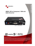
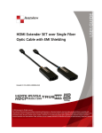
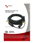
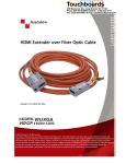
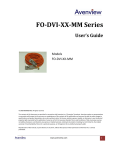
DVI Dual Link Extender over 2 Strand Multi-Mode Fiber Optic Cable Model #: FO-DVI-DL-330X © 2011 Avenview Inc. All rights reserved. The contents of this document are provided in connection with Avenview Inc. (“Avenview”) products. Avenview makes no representations or warranties with respect to the accuracy or completeness of the contents of this publication and reserves the right to make changes to specifications and product descriptions at any time without notice. No license, whether express, implied, or otherwise, to any intellectual property rights is granted by this publication. Except as set forth in Avenview Standard Terms and Conditions of Sale, Avenview assumes no liability whatsoever, and disclaims any express or implied warranty, relating to its products including, but not limited to, the implied warranty of merchantability, fitness for a particular purpose, or infringement of any intellectual property right. Reproduction of this manual, or parts thereof, in any form, without the express written permission of Avenview Inc. is strictly prohibited. www.avenview.com 1 Table of Contents Section 1: Getting Started ...................................................................................................................... 3 1.1 Important Safeguards ............................................................................................................ 3 1.2 Safety Instructions ................................................................................................................. 3 1.3 Regulatory Notices Federal Communications Commission (FCC) ......................................... 4 1.4 Introduction ........................................................................................................................... 4 1.5 Package Contents................................................................................................................... 4 1.6 Before Installation.................................................................................................................. 5 1.7 Installation ............................................................................................................................. 6 Section 2: Specifications......................................................................................................................... 7 2.1 Signal Pin Assignment (Single Link) .............................................................................................. 8 2.2 Signal Pin Assignment (Dual Link) ................................................................................................ 9 www.avenview.com 2 Section 1: Getting Started 1.1 Important Safeguards Please read all of these instructions carefully before you use the device. Save this manual for future reference. What the warranty does not cover Any product, on which the serial number has been defaced, modified or removed. Damage, deterioration or malfunction resulting from: Accident, misuse, neglect, fire, water, lightning, or other acts of nature, unauthorized product modification, or failure to follow instructions supplied with the product. Repair or attempted repair by anyone not authorized by us. Any damage of the product due to shipment. Removal or installation of the product. Causes external to the product, such as electric power fluctuation or failure. Use of supplies or parts not meeting our specifications. Normal wear and tear. Any other causes which does not relate to a product defect. Removal, installation, and set-up service charges. 1.2 Safety Instructions The Avenview FO-DVI-DL-330X, DVI Dual Link Extender over Fiber Optic, has been tested for conformance to safety regulations and requirements, and has been certified for international use. However, like all electronic equipment’s, the FO-DVI-DL-330X should be used with care. Read the following safety instructions to protect yourself from possible injury and to minimize the risk of damage to the unit. Do not dismantle the housing or modify the module. Dismantling the housing or modifying the module may result in electrical shock or burn. Refer all servicing to qualified service personnel. Do not attempt to service this product yourself as opening or removing housing may expose you to dangerous voltage or other hazards Keep the module away from liquids. Spillage into the housing may result in fire, electrical shock, or equipment damage. If an object or liquid falls or spills on to the housing, unplug the module immediately. Have the module checked by a qualified service engineer before using it again. Do not use liquid or aerosol cleaners to clean this unit. Always unplug the power to the device before cleaning. www.avenview.com 3 1.3 Regulatory Notices Federal Communications Commission (FCC) This equipment has been tested and found to comply with Part 15 of the FCC rules. These limits are designed to provide reasonable protection against harmful interference in a residential installation. Any changes or modifications made to this equipment may void the user’s authority to operate this equipment. 1.4 Introduction Fiber Optic Cable is not included in the package Avenview FO-DVI-DL-330X Series with fiber optic cable system lets you extend dual link digital signal up to 100m (330 feet). - 1.5 High Speed and long distance transmission Uses 2 strand multi-mode LC fiber optic cable Supports both Single link and Dual link by selectable function switch Supports up to Dual Link WQXGA (2560 x 1600) resolution and WUXGA (1920x1200) Single link Self-detecting function for EDID Supports two mode for DDC o Real Mode: Uses one CAT5 cable for DDC o Emulation: Pseudo DDC detection function for EDID information (2560x1600) Package Contents Before you start the installation of the converter, please check the package contents. - FO-DVI-DL-330X Transmitter FO-DVI-DL-330X Receiver Power Adapter (+5VDC 2A) x1 x1 x1 - User’s Manual x1 www.avenview.com 4 1.6 Before Installation Put the product in an even and stable location. If the product falls down or drops, it may cause an injury or malfunction. Don’t place the product in too high temperature (over 50°C), too low temperature (under 0°C) or high humidity. Use the DC power adapter with correct specifications. If inappropriate power supply is used then it may cause a fire. Do not twist or pull by force ends of the optical cable. It can cause malfunction. www.avenview.com 5 1.7 Installation Avenview FO-DVI-DL-330X is composed of a transmitter and a receiver. The Transmitter should be connected to the computer’s DVI Port and the Receiver should be connected the DVI Port of the digital display device. Avenview FO-DVI-DL-330X Transmitter is designed to be used with the LC type standard optical cable. Transmitter and Receiver have each of 7 Optical port which are marked on the optical port of the fiber cable connection. To setup Avenview FO-DVI-DL-330X follow these steps for connecting to a device: 1. Connect FO-DVI-DL-330X Transmitter unit to DVI source 2. Connect FO-DVI-DL-330X Receiver unit to DVI port of display. 3. Connect 2 Strand Fiber Optic LC Type cable to both Transmitter and Receiver. 4. Plug the power to Receiver Unit. 5. Power on DVI Source and DVI Display. Use the DC adapter (included in the package) for the Receiver. The Transmitter which is connected to a computer uses power from the computer. If Transmitter power LED doesn’t light up after PC is turned on, then use the external power adapter for Transmitter. 1.8 Function Switch EDID: Switch in front of Transmitter - REAL: EDID data of connected monitor is transmitted between Transmitter and Receiver in real time - through UTP cable. Emulation: Certain EDID data pre-set in the Transmitter is used in signal transmission. UTP cable is not necessary. EDID: Switch in front of Transmitter - Single: When you use Single link display, select ‘Single’ switch. Dual: When you use Dual link display, select ‘Dual’ switch. www.avenview.com 6 Section 2: Specifications Item Description Units Unit Description Input Signal FO-DVI-DL-330X (Transmitter) FO-DVI-DL-330X (Receiver DVI Dual Link Transmitter DVI Dual Link Receiver TMDS Signal (DVI 1.0 Standard) Output Signal Video Bandwidth Supported Resolution & Distance Optical Converter DVI Connector Optical Connector DDC Link Connector Fiber Type Dimensions (L x W x H) TMDS Signal (DVI 1.0 Standard) 1.65Gbps (Single Link) Single Link: WUXGA 1920 x 1200 @ 100 meters ( 330 feet) Dual Link: WQXGA 2560 x 1600 @ 100 meters (330 feet) 2 ch 850 nm Multi-Mode VCSEL 2 ch GaAs PIN photo Diode 24 pin DVI-D Plug 2 LC Connector Rj45 50/125 µm Multi-mode glass fiber 3.4” x 5.3” x 1” Power Supply Power Consumption 5V 2A DC 1.5W (max) Environmental Operating Temperature Storage Temperature Relative Humidity 32˚ ~ 104˚F (0˚ to 40˚C) -4˚ ~ 140˚F (-20˚ ~ 60˚C) 20~90% RH (no condensation) www.avenview.com 7 2.1 Signal Pin Assignment (Single Link) TRANSMITTER Pin Signal Assignment Pin Signal Assignment Pin Signal Assignment 1 T.M.D.S. Data2- 9 T.M.D.S. Data1- 17 T.M.D.S. Data0- 2 T.M.D.S. Data2+ 10 T.M.D.S. Data1+ 18 T.M.D.S. Data0+ 3 T.M.D.S. Data2 Shield 11 T.M.D.S. Data1 Shield 19 T.M.D.S. Data0 Shield 4 No Connect 12 No Connect 20 No Connect 5 No Connect 13 No Connect 21 No Connect 6 DDC Clock (SCL) 14 +5V Power 22 T.M.D.S. Clock Shield 7 DDC Data (SDA) 15 Ground (for +5V) 23 T.M.D.S. Clock+ 8 No Connect 16 Hot Plug Detect 24 T.M.D.S. Clock- Pin Signal Assignment Pin Signal Assignment Pin Signal Assignment 1 T.M.D.S. Data2- 9 T.M.D.S. Data1- 17 T.M.D.S. Data0- 2 T.M.D.S. Data2+ 10 T.M.D.S. Data1+ 18 T.M.D.S. Data0+ 3 T.M.D.S. Data2 Shield 11 T.M.D.S. Data1 Shield 19 T.M.D.S. Data0 Shield 4 No Connect 12 No Connect 20 No Connect 5 No Connect 13 No Connect 21 No Connect 6 DDC Clock (SCL) 14 Out +5V Power 22 T.M.D.S. Clock Shield 7 DDC Data (SDA) 15 Ground (for Out +5V) 23 T.M.D.S. Clock+ 8 No Connect 16 Hot Plug Detect 24 T.M.D.S. Clock- RECEIVER www.avenview.com 8 2.2 Signal Pin Assignment (Dual Link) TRANSMITTER Pin Signal Assignment Pin Signal Assignment Pin Signal Assignment 1 T.M.D.S. Data2- 9 T.M.D.S. Data1- 17 T.M.D.S. Data0- 2 T.M.D.S. Data2+ 10 T.M.D.S. Data1+ 18 T.M.D.S. Data0+ 3 T.M.D.S. Data2 Shield 11 T.M.D.S. Data1 Shield 19 T.M.D.S. Data0 Shield 4 T.M.D.S. Data4- 12 No Connect 20 T.M.D.S. Data5- 5 T.M.D.S. Data4+ 13 No Connect 21 T.M.D.S. Data5+ 6 DDC Clock (SCL) 14 +5V Power 22 T.M.D.S. Clock Shield 7 DDC Data (SDA) 15 Ground (for +5V) 23 T.M.D.S. Clock+ 8 No Connect 16 Hot Plug Detect 24 T.M.D.S. Clock- Pin Signal Assignment Pin Signal Assignment Pin Signal Assignment 1 T.M.D.S. Data2- 9 T.M.D.S. Data1- 17 T.M.D.S. Data0- 2 T.M.D.S. Data2+ 10 T.M.D.S. Data1+ 18 T.M.D.S. Data0+ 3 T.M.D.S. Data2 Shield 11 T.M.D.S. Data1 Shield 19 T.M.D.S. Data0 Shield 4 T.M.D.S. Data4- 12 No Connect 20 No Connect 5 T.M.D.S. Data4+ 13 No Connect 21 No Connect 6 DDC Clock (SCL) 14 Out +5V Power 22 T.M.D.S. Clock Shield 7 DDC Data (SDA) 15 Ground (for Out +5V) 23 T.M.D.S. Clock+ 8 No Connect 16 No Connect 24 T.M.D.S. Clock- RECEIVER www.avenview.com 9 Disclaimer While every precaution has been taken in the preparation of this document, Avenview Inc. assumes no liability with respect to the operation or use of Avenview hardware, software or other products and documentation described herein, for any act or omission of Avenview concerning such products or this documentation, for any interruption of service, loss or interruption of business, loss of anticipatory profits, or for punitive, incidental or consequential damages in connection with the furnishing, performance, or use of the Avenview hardware, software, or other products and documentation provided herein. Avenview Inc. reserves the right to make changes without further notice to a product or system described herein to improve reliability, function or design. With respect to Avenview products which this document relates, Avenview disclaims all express or implied warranties www.avenview.com 10 regarding such products, including but not limited to, the implied warranties of merchantability, fitness for a particular purpose, and non-infringement. www.avenview.com 11