1
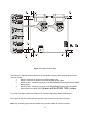
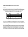
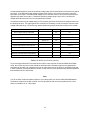
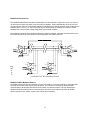
C (C
C
MODEL USB-COM-2SM
USER MANUAL
FILE: MUSB-COM-2SM.A1a
Notice
The information in this document is provided for reference only. Portwell does not assume any liability
arising out of the application or use of the information or products described herein. This document may
contain or reference information and products protected by copyrights or patents and does not convey any
license under the patent rights of Portwell, nor the rights of others.
IBM PC, PC/XT, and PC/AT are registered trademarks of the International Business Machines
Corporation.
Printed in USA. Copyright 2007 by Portwell I/O Products Inc. All rights reserved.
WARNING!!
ALWAYS CONNECT AND DISCONNECT YOUR FIELD CABLING WITH
THE COMPUTER POWER OFF. ALWAYS TURN COMPUTER POWER
OFF BEFORE INSTALLING A CARD. CONNECTING AND
DISCONNECTING CABLES, OR INSTALLING CARDS INTO A SYSTEM
WITH THE COMPUTER OR FIELD POWER ON MAY CAUSE DAMAGE
TO THE I/O CARD AND WILL VOID ALL WARRANTIES, IMPLIED OR
EXPRESSED.
2
Warranty
Prior to shipment, Portwell equipment is thoroughly inspected and tested to applicable specifications.
However, should equipment failure occur, Portwell assures its customers that prompt service and support
will be available. All equipment originally manufactured by Portwell which is found to be defective will be
repaired or replaced subject to the following considerations.
Terms and Conditions
If a unit is suspected of failure, contact Portwell' Customer Service department. Be prepared to give the
unit model number, serial number, and a description of the failure symptom(s). We may suggest some
simple tests to confirm the failure. We will assign a Return Material Authorization (RMA) number which
must appear on the outer label of the return package. All units/components should be properly packed for
handling and returned with freight prepaid to the Portwell designated Service Center, and will be returned
to the customer's/user's site freight prepaid and invoiced.
Coverage
First Three Years: Returned unit/part will be repaired and/or replaced at Portwell option with no charge for
labor or parts not excluded by warranty. Warranty commences with equipment shipment.
Following Years: Throughout your equipment's lifetime, Portwell stands ready to provide on-site or in-plant
service at reasonable rates similar to those of other manufacturers in the industry.
Equipment Not Manufactured by Portwell
Equipment provided but not manufactured by Portwell is warranted and will be repaired according to the
terms and conditions of the respective equipment manufacturer's warranty.
General
Under this Warranty, liability of Portwell is limited to replacing, repairing or issuing credit (at Portwell
discretion) for any products which are proved to be defective during the warranty period. In no case isPortwell
liable for consequential or special damage arriving from use or misuse of our product. The
customer is responsible for all charges caused by modifications or additions to Portwell equipment not
approved in writing by Portwell or, if in Portwell opinion the equipment has been subjected to abnormal
use. "Abnormal use" for purposes of this warranty is defined as any use to which the equipment is
exposed other than that use specified or intended as evidenced by purchase or sales representation.
Other than the above, no other warranty, expressed or implied, shall apply to any and all such equipment
furnished or sold by Portwell.
3
TABLE OF CONTENTS
Chapter 1: Introduction . . . . . . . . . . . . . . . . . . . . . . . . . . . . . . . . . . . . . . . . . . . . . . . . . . . . . . . . . . . . . . 5
Specifications . . . . . . . . . . . . . . . . . . . . . . . . . . . . . . . . . . . . . . . . . . . . . . . . . . . . . . . . . . . . . . . . 6
Figure 1-1: Block Diagram . . . . . . . . . . . . . . . . . . . . . . . . . . . . . . . . . . . . . . . . . . . . . . . . 8
Chapter 2: Installation . . . . . . . . . . . . . . . . . . . . . . . . . . . . . . . . . . . . . . . . . . . . . . . . . . . . . . . . . . . . . . . 9
Hardware Installation . . . . . . . . . . . . . . . . . . . . . . . . . . . . . . . . . . . . . . . . . . . . . . . . . . . . . . . . . . . 9
Chapter 3: Option Selection . . . . . . . . . . . . . . . . . . . . . . . . . . . . . . . . . . . . . . . . . . . . . . . . . . . . . . . . . 10
Figure 3-1: Option Selection Map . . . . . . . . . . . . . . . . . . . . . . . . . . . . . . . . . . . . . . . . . . 11
Chapter 4: Address Selection . . . . . . . . . . . . . . . . . . . . . . . . . . . . . . . . . . . . . . . . . . . . . . . . . . . . . . . . 12
Chapter 5: Programming . . . . . . . . . . . . . . . . . . . . . . . . . . . . . . . . . . . . . . . . . . . . . . . . . . . . . . . . . . . . 13
Chapter 6: Connector Pin Assignments . . . . . . . . . . . . . . . . . . . . . . . . . . . . . . . . . . . . . . . . . . . . . . . 14
Table 6-1: Serial Connector Pin Assignments . . . . . . . . . . . . . . . . . . . . . . . . . . . . . . . . 14
Appendix A: Application Considerations . . . . . . . . . . . . . . . . . . . . . . . . . . . . . . . . . . . . . . . . . . . . . . . 15
Introduction . . . . . . . . . . . . . . . . . . . . . . . . . . . . . . . . . . . . . . . . . . . . . . . . . . . . . . . . . . . . . . . . . . . . 15
Table A-1: Connections Between Two RS422 Devices . . . . . . . . . . . . . . . . . . . . . . . . 15
Balanced Differential Signals . . . . . . . . . . . . . . . . . . . . . . . . . . . . . . . . . . . . . . . . . . . . . . . . . . . . . 15-16
Table A-2: RS422 Specification Summary . . . . . . . . . . . . . . . . . . . . . . . . . . . . . . . . 16
RS485 Data Transmission . . . . . . . . . . . . . . . . . . . . . . . . . . . . . . . . . . . . . . . . . . . . . . . . . . . 17
Figure A-1: Typical RS485 Two-Wire Network . . . . . . . . . . . . . . . . . . . . . . . . . . . . 17
4
Chapter 1: Introduction
The USB-COM-2SM is a USB interface device, incorporating a USB 4-port hub internally to provide two
ports of Serial Communication in one product. The following paragraphs will first describe the Onboard
Serial ports.
Serial Communication
This Serial Adapter was designed for effective multipoint transmission in any one of three modes on each
channel. These modes are RS232, RS422 and RS485 (EIA485) protocol.
The card features two independent, asynchronous serial ports.
RS422 Balanced Mode Operation
The board supports RS422 communications and uses differential balanced drivers for long range and
noise immunity. The board also has the capability to add load resistors to terminate the communications
lines. RS422 communications requires that a transmitter supply a bias voltage to ensure a known "zero"
state. Also, receiver inputs at each end of the network should be terminated to eliminate "ringing". The
board supports biasing by default and supports termination by jumpers on the card. If your application
requires the transmitter to be un-biased, please contact the factory.
RS485 Balanced Mode Operation
The board supports RS485 communications and uses differential balanced drivers for long range and
noise immunity. RS485 operation involves switchable transceivers and the ability to support multiple
devices on a single "party line". The RS485 specification defines a maximum of 32 devices on a single
line. The number of devices served on a single line can be expanded by use of "repeaters".
This board also has the capability to add load resistors to terminate the communications lines. RS485
communications requires that one transmitter supply a bias voltage to ensure a known "zero" state when
all transmitters are off. Also, receiver inputs at each end of the network should be terminated to eliminate
"ringing". The card supports biasing by default and supports termination by jumpers on the card. If your
application requires the transmitter to be un-biased, please contact the factory.
COM Port Compatibility
The FT232BM UARTs are used as Asynchronous Communication Elements (ACE). These include 128byte transmit & 384-byte receive buffers to protect against lost data in multitasking operating systems,
while maintaining 100 percent compatibility with the original IBM serial port. The system assigns the
address(es).
A crystal oscillator is located on the board. This oscillator permits precise selection of baud rate up to 921.6K
bps.
The driver/receiver used (SP491 in non-RS232 modes) is capable of driving extremely long communication
lines at high baud rates. It can drive up to +60 mA on balanced lines and receive inputs as low as 200 mV
differential signal superimposed on common mode noise of +12 V or -7 V. In case of communication conflict,
the driver/receivers feature thermal shutdown.
The driver/receiver used in RS232 mode is the ICL3243.
5
Communication Mode
The board supports Half-Duplex communications with a 2-wire cable connection. Half-Duplex allows traffic
to travel in both directions, but only one way at a time. RS485 communications commonly use the Half-Duplex
mode since they share only a single pair of wires.
Baud Rate Ranges
The board has capability for baud rates up to 921.6K bps.
Serial Specifications
Communications Interface
•
I/O Connection:
•
Serial Ports:
•
Character length:
•
Parity:
•
Stop Interval:
•
Serial Data Rates:
•
Receiver Input Sensitivity:
•
Common Mode Rejection:
•
Transmitter Output Drive Capability:
Standard USB connector
2 male D-sub 9-pin connectors
5, 6, 7, or 8 bits
Even, odd or none
1, 1.5, or 2 bits
Up to 921.6K
+200 mV, differential input
+12V to -7V
60 mA, with thermal shutdown
Bus Type
USB 1.1, USB 2.0 Host Compatible
Environmental
•
Operating Temperature Range:
•
Storage temperature Range:
•
Humidity:
•
Power Required:
Current:
•
Size:
0/C to + 60/C
-50/C to +120/C
5% to 95%, non-condensing
120mA maximum (see below)
0-60mA per COM channel
4 inches wide by 4 inches deep by 1.25 inches high
6
USB Connector
The USB connector is a Type B connector and mates with the cable provided. The USB port provides
communication signals along with +5 VDC power. The board is powered from the USB port or alternate
USB connector.
A second USB Input Connector (P4) in parallel to the Type B connector is supplied. This second
connector is a USB (OTG) connector.
Auxiliary USB Connector
This board has an optional feature. You can cable an extra USB type A connector to the onboard USB1.1
hub. This would provide an additional, "daisy-chained" USB 1.1 bus to which you can attach any 3rd party
USB devices you may wish.
LED
There are three LEDs present on the product, functioning as follows:
Indicator
Function
1
USB Power Present
2
Serial Port 1 Activity
3
Serial Port 2 Activity
7
Figure 1-1: Block Diagram
8
Chapter 2: Installation
Software CD Installation
These paragraphs are intended to detail the software installation steps as well as describe what is being
installed.
The software provided with this board is contained on one CD and must be installed onto your hard disk
prior to use. To do this, perform the following steps as appropriate for your software format and operating
system. Substitute the appropriate drive letter for your CD-ROM or disk drive where you see d: in the
examples below.
WIN95/98/Me/NT/2000/XP/2003
a.
Place the CD into your CD-ROM drive.
b.
The CD should automatically run the install program. If the install program does not click START |
RUN and type BGLQR?JJ, click OK or press -.
c.
Follow the on-screen prompts to install the software for this board.
LINUX
1.
Please refer to linux.htm on the CD-ROM for information on installing under linux.
Hardware Installation
The unit can be connected to any USB 2.0 or USB 1.1 port. Please install the software package before
plugging the hardware into the system.
9
Chapter 3: Option Selection
Refer to the setup programs on the CD provided with the board. Also, refer to the Block diagram and the
Option Selection Map when reading this section of the manual.
Terminations
A transmission line should be terminated at the receiving end in its characteristic impedance. Installing a
jumper at the locations labeled RS485-LD applies a 120S load across the transmit/receive input/output for
RS485 operation.
Jumpers having to do with the termination of each channel are located near the output connector. They
are labeled by channel. The load jumper is labeled “TERM”. The other two jumpers are used to connect
the transmit and receive lines for the two wire RS485 mode.
In RS485 operations where there are multiple terminals, only the RS485 ports at each end of the network
should have terminating impedance as described above. To terminate the COM A port, place a jumper at
the location labeled Ch A - RS485. To terminate the COM B port place jumpers at the location labeled Ch
B - RS485.
Also, for RS485 operation, there must be a bias on the TRX+ and TRX- lines. If the adapter is not to
provide that bias, consult the factory for technical support.
Data Cable Wiring
Signal
Pin Connection
Ain/out+
2
Ain/out3
100S to Ground
5
10
Figure 3-1: Option Selection Map
This board has 2 separate channels which can be individually configured. Each channel can be used in
one of four modes:
1
RS232 - Install the top jumper in the RS232 position (left)
2
RS422 - Install the top jumper in the RS422/RS485 position (right)
3
RS485 (4 wire) - Install the top jumper in the RS422/RS485 position (right) and the RS485
Mode jumper
4
RS485 (2 wire) - Install the top jumper in the RS422/RS485 position (right), the RS485
Mode jumper, the RS485 TxRx+
jumper and the RS485 TxRx- jumper.
To provide a termination load in the RS485 mode, install the appropriate RS485 TERM jumper.
The jumpers on the card must be properly placed in order to have the card function properly.
Note: Any unneeded jumpers that are installed can cause the adapter to function incorrectly.
11
Chapter 4: Address Selection
Use the provided driver to access the USB board. This driver will allow you to determine how many
supported USB devices are currently installed, and each device’s type. This information is returned as a
Vendor ID (VID), Product ID (PID) and Device Index.
The board’s VID is “0x1605", and its PID is “0x8030".
The Device Index is determined by how many of the device you have in your system, and provides a
unique identifier allowing you to access a specific board at will.
12
Chapter 5: Programming
Sample Programs
There are sample programs provided with the USB-COM-2SM card in C, Pascal, QuickBASIC, and
several Windows languages. DOS samples are located in the DOS directory and Windows samples are
located in the WIN32 directory.
Windows Programming
The USB-COM-2SM card installs into Windows as COM ports. Thus the Windows standard API functions
can be used. In particular:
<
<
<
CreateFile() and CloseHandle() for opening and closing a port.
SetupComm(), SetCommTimeouts(), GetCommState(), and SetCommState() to set and change a port’s settings.
ReadFile() and WriteFile() for accessing a port.
See the documentation for your chosen language for details.
Under DOS, the process is identical to programming any 16550- or 16750-compatible UART.
Address Map
The core of the UART function is supplied by the FTDI FT232BM chip.
13
Chapter 6: Connector Pin Assignments
DB-9 Male Pin for
each of Ch A-G
Ch x - 1
RS-232 Signals
(Industry Standard)
DCD
RS-485 Signals
(2 Wire)
Ch x - 2
RX
RX-/TXTX+/RX+
Ch x - 3
TX
TX-/RX-
TX-
Ch x - 4
DTR
Ch x - 5
Ch x - 6
Gnd
DSR
Gnd
Gnd
Ch x - 7
RTS
Ch x - 8
CTS
Ch x - 9
RI
RX+/TX+
RX+
Table 6-1: Serial Connector Pin Assignments
14
RS-422 Signals
(Also 4wire RS485)
RXTX+
Appendix A: Application Considerations
Introduction
Working with RS422 and RS485 devices is not much different from working with standard RS232
serial devices and these two standards overcome deficiencies in the RS232 standard. First, the
cable length between two RS232 devices must be short; less than 50 feet at 9600 baud. Second, many
RS232 errors are the result of noise induced on the cables. The RS422 standard permits cable lengths up
to 5000 feet and, because it operates in the differential mode, it is more immune to induced noise.
Connections between two RS422 devices (with CTS ignored) should be as follows:
Device #1
Device #2
Signal
Pin No.
Signal
Pin No.
Gnd
5
Gnd
5
+
2
RX
+
9
TX-
3
RX-
1
9
+
2
-
3
TX
RX
+
RX
-
TX
1
TX
Table A-1: Connections Between Two RS422 Devices
A third deficiency of RS232 is that more than two devices cannot share the same cable. This is also true
for RS422 but RS485 offers all the benefits of RS422 plus allows up to 32 devices to share the same
twisted pairs. An exception to the foregoing is that multiple RS422 devices can share a single cable if only
one will talk and the others will all receive.
Balanced Differential Signals
The reason that RS422 and RS485 devices can drive longer lines with more noise immunity than RS232
devices is that a balanced differential drive method is used. In a balanced differential system, the voltage
produced by the driver appears across a pair of wires. A balanced line driver will produce a differential
voltage from ±2 to ±6 volts across its output terminals. A balanced line driver can also have an input
"enable" signal that connects the driver to its output terminals. If the "enable signal is OFF, the driver is
disconnected from the transmission line. This disconnected or disabled condition is usually referred to as
the "tristate" condition and represents a high impedance. RS485 drivers must have this control capability.
RS422 drivers may have this control but it is not always required.
15
A balanced differential line receiver senses the voltage state of the transmission line across the two signal
input lines. If the differential input voltage is greater than +200 mV, the receiver will provide a specific
logic state on its output. If the differential voltage input is less than -200 mV, the receiver will provide the
opposite logic state on its output. A maximum operating voltage range is from +6V to -6V allows for
voltage attenuation that can occur on long transmission cables.
A maximum common mode voltage rating of ±7V provides good noise immunity from voltages induced on
the twisted pair lines. The signal ground line connection is necessary in order to keep the common mode
voltage within that range. The circuit may operate without the ground connection but may not be reliable.
Parameter
Conditions
Driver Output Voltage (unloaded)
Driver Output Voltage (loaded)
LD and LDGND
jumpers in
Min.
Max.
4V
6V
-4V
-6V
2V
-2V
Driver Output Resistance
50S
Driver Output Short-Circuit Current
±150 mA
Driver Output Rise Time
10% unit interval
Receiver Sensitivity
±200 mV
Receiver Common Mode Voltage Range
±7V
Receiver Input Resistance
4KS
Table A-2: RS422 Specification Summary
To prevent signal reflections in the cable and to improve noise rejection in both the RS422 and RS485
mode, the receiver end of the cable should be terminated with a resistance equal to the characteristic
impedance of the cable. (An exception to this is the case where the line is driven by an RS422 driver that
is never "tristated" or disconnected from the line. In this case, the driver provides a low internal impedance
that terminates the line at that end).
Note
You do not have to add a terminator resistor to your cables when you use the USB-COM-2SM adapter.
Termination resistors for the RX+ and RX- lines are provided on the card and are placed in the circuit
when you install the Ch X - LD jumpers.
16
RS485 Data Transmission
The RS485 Standard allows a balanced transmission line to be shared in a party-line mode. As many as
32 driver/receiver pairs can share a two-wire party line network. Many characteristics of the drivers and
receivers are the same as in the RS422 Standard. One difference is that the common mode voltage limit is
extended and is +12V to -7V. Since any driver can be disconnected (or tristated) from the line, it must
withstand this common mode voltage range while in the tristate condition.
The following illustration shows a typical multidrop or party line network. Note that the transmission line is
terminated on both ends of the line but not at drop points in the middle of the line.
Fig
ure
A1:
Ty
pical RS485 Two-Wire Multidrop Network
RS485 Four-Wire Multidrop Network
An RS485 network can also be connected in a four-wire mode. In a four-wire network it's necessary that
one node be a master node and all others be slaves. The network is connected so that the master
communicates to all slaves and all slaves communicate only with the master. This has advantages in
equipment that uses mixed protocol communications. Since the slave nodes never listen to another
slave's response to the master, a slave node cannot reply incorrectly.
17
Customer Comments
If you experience any problems with this manual or just want to give us some feedback, please email us
at: [email protected]. Please detail any errors you find and include your mailing address so that we
can send you any manual updates.
18