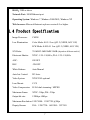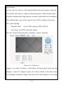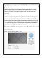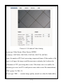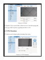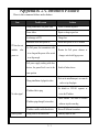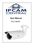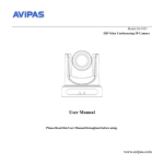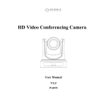
1
HD Network IP Speed dome Camera USER MANUAL 0 Attention FCC Warning HD IP camera fully complies with Article 15 of FCC rules about Class A Digital Devices after thorough test. To some extent, those rules ensure its normal operation without external interference. The device is electromagnetic. Please do read the manual carefully before use, or it might cause interference to radio communications. Meanwhile, the installation under some circumstances can not completely avoid interference. Before wiring and operating the devices, please read this manual well and keep it for future reference in need. Key Safety Instructions and Warnings: Please read and retain the manual well for future reference; Do not place the device near water, fire or other high-intensity Please keep good ventilation environment for the product; Please wipe the surface with a dry soft cloth; Please disconnect the power cord when the device is not used; The device uses the auxiliary equipment and spare parts recommend by the Please do not place the power adapters and other cables underground or in Do not open the housing without authorization; Please consult with Please remain packing boxes in case of delivery if necessary. electromagnetic radiation; manufacturer; some crowding; technician for maintenance; Indicate error operation. The internal non-insulated parts are likely to cause 1 harmful voltage. Please operate the device in strict accordance to the manual. Indicate that user should install and operate the device strictly according to the manual. Warning: To avoid moisture lead or fire, please do not put the device in wet open places! Content Content .............................................................................. 2 Chapter 1 System Overview ............................................... 4 1.1 Product Description ...................................... 4 1.2 Product Feature .............................................. 4 1.3 System Requirement ........................................ 6 1.4 Product Specification .................................. 7 1.5 Precautions ...................................................... 8 Chapter 2 IP Cam installation interface .......................... 10 2.1 Installation Notice .................................. 10 3.1 Connecting the device .............................. 11 3.2 Setting the IE browser ............................ 11 3.3 Install Video Software ............................ 13 Chapter 4 System Operation Guide ................................ 16 4.1 Login .............................................................. 16 2 4.2 Browser .......................................................... 18 4.2.1 Video Browsing ..................................... 18 4.2.2 PTZ control......................................... 19 4.2.3 PTZ functions ..................................... 20 4.2.4 Common shortcuts .............................. 21 4.3 Setting .......................................................... 22 4.3.1System .................................................... 22 4.3.2 Network .............................................. 26 4.3.4 Management software ........................ 32 4.3.5 IP Cameras .......................................... 33 4.3.6 Audio & Video.................................... 38 4.3.7 PTZ Funciton ......................................... 44 4.3.8 Alarm .................................................. 47 4.3.9 User .................................................... 48 4.3.10 log ........................................................ 49 Appendix 1Toroid filter installation manual .................. 50 3 Chapter 1 System Overview 1.1 Product Description The manual mainly introduces the setting and operation of HD IP cameras. HD IP camera combines CMOS sensor and the latest network encoding technology, provides the users with a full live video capture system of high definition, high SN ratio and low illumination. It is widely used for buildings, shopping malls, airports, warehouse, streets and other city surveillance environment. The device adopts the advanced image processing technology, provides H.264 and MJPEG dual encoding method and supports tri-streaming. Users can freely choose and browse for storage and real-time video. The device supports motion detection function and through the management platform it is in a position to execute intelligent monitoring program and storage strategy; It has convenient SD card storage (optional), which automatically records the video when alarm or network error; User can manually record as well when browsing the video, which is higher and safer for the system safety. It supports QoS service and provides better video transmission and quality service. 1.2 Product Feature Key features of the HD IP Camera: 4 CMOS Image sensor Automatic IR-CUT filter, Color/Black & White auto switch H.264 / MJPEG dual encoding, tri-streaming Support high frame output Support two-way audio, G.711 encoding format Support Motion Detection Support 2-CH alarm input, 1-CH relay output (optional) Support a variety of alarm processing, eg. Sending emails, FTP uploading, audio warning, SD card storage (trigger recording, optional) and relay output (optional) Support TCP/IP, HTTP, ICMP, PPPoE, DHCP, UDP, SMTP, RTP, RTSP, SNMP, ARP and other protocols Support QoS service and provide better video transmission and quality service Support multi-user real-time access and parameter configuration through the Web Server Support network remote upgrade PoE/12VDC power Except the features above, the device has the following features: Support high resolution image compression technology The device supports 1080P(1920*1080), 960P(1280*960), 720P(1280* 720), D1(720*576), VGA(640*480)and etc. Please refer to the precise internal 5 parameters according to different models. Provide comprehensive network monitoring and transmission mechanism. IP Camera connects 10M/100M network port through RJ45. It supports full TCP/IP protocols (TCP/IP, HTTP, ICMP, UDP, SMTP, RTP, RTSP, SNMP), adjusts its bit flow rate and frame rate, so as to adapt itself to strict monitoring system requirement. It is possible to set date, time, OSD for the interface and save the camera position. Flexibly adjust color saturation, hue, contrast, brightness of the screen to meet different visual requirements. Set alarm and audio functions through web page. Support motion detection function (4 motion zones to set) Support a variety of alarm processing, eg. Sending emails, FTP uploading, audio warning, and relay output (optional) Widely applied The IP Camera adopts encrypted TCP/IP protocol transmission, provides a shortcut high-performance, high-stability and easy maintenance network system, better use for professional monitoring cases. 1.3 System Requirement The computer has some certain requirements for well displaying output video and controlling the camera: Processor: Intel Pentium 4 2.4 GHz dual core or higher 6 RAM:2GB or above Network Port: 100M Ethernet port Operating System: Windows 7 ,Windows 2000/2003, Windows XP Web browser: Microsoft Internet explorer version 8.0 or higher 1.4 Product Specification Image Processor: CMOS Low Illumination: Color Mode: 0.05-1 Lux @F1.2 (30IRE, AGC ON) B/W Mode: 0.005-0.1 Lux @F1.2 (30IRE, AGC ON) S/N Ratio: 70.1dB/83.5dB/90dB/110dB (depend on different models) Electronic Shutter: NTSC: 1/30~1/8,000 s; PAL: 1/25~1/8,000 s AGC: ON/OFF BLC: ON/OFF White Balance: Auto/Manual Auto Iris Control: DC drive Video System: NTSC/PAL optional Lens Mount: C/CS Video Compression: H.264 dual streaming / MJPEG Maximum Frame: NTSC: 30fps; PAL: 25fps Output bit rate: 128Kbps~6Mbps Maximum Resolution: 1920*1080、1280*720 @30fps Deputy Stream: PAL:1280*720、640*480、352*288 7 Audio Compression: G.711 Audio input: 1-CH, line level, impedance: 1kΩ Audio output: 1-CH, line level, impedance: 600Ω Motion detection: Support Password protection: Support Network: 1 of RJ45 10/100M adaptive to POE Network Protocol: TCP/IP, HTTP, ICMP, PPPoE, DHCP, UDP, SMTP, RTP, RTSP, SNMP, ARP Alarm input: 2-way, semaphore Alarm output: 1-way, switch Network remote upgrade: Support Power Supply: PoE/12VDC/24VAC Power: depend on different models Product Dimension: depend on different models Working Temperature: -10℃ ~ 50℃ (14°F ~ 122°F) Working Humidity: 0~90% RH (non-condensing) 1.5 Precautions First please set the network data after login. The gateway address is the one to connect the IP camera. IP address should be different from other devices’ IP address. Otherwise, video is not available. 8 If the IP Camera supports PoE for power supply, please refer to the precise parameters of the power switches to connect the devices. And, further test the maximum longest cables of the power, so as to avoid inadequate output power affecting the normal work of the IP Camera or damaging the switchboard. 9 Chapter 2 IP Cam installation interface 2.1 Installation Notice 1. Please do not drop or strongly strike the device; 2. Please do not directly expose the device to the sunshine or bright light. Otherwise, it shortens its life. 3. Please avoid installing the device in the following environment: temperature over 50℃ or below -10℃, higher humidity, rain, frequent vibration or possibly shock places. 4. When the environment goes too dark and the image quality gets worse, we suggest installing auxiliary lighting nearby. 10 Chapter 3 IE browser setting Browsing live video, User is supposed to adjust the monitor or the IE browser for other video picture and set some relevant data according to the interface prompt. Please pay attention to the following points: Internet Explorer 8.0 or higher version supports the device; ActiveX is a must to install to support Directx 9.0c video browser software; 3.1 Connecting the device The device can be directly connected to the computer and the network; Please use the cross-over cable when connecting to the computer; Please use the straight through cable when connecting to the network. Note: Please check the power cables are solid or not when connecting the power supply. 3.2 Setting the IE browser User can browse the video through IE, HVMS or other software, while ActiveX is required to install. Otherwise, video is not available. And, user is supposed to set the IE security level before downloading the plugin. 1. From menu, click “tool”, then choose “Internet options”. 2. Then click “Security” as the follows: 11 Picture 3-1 3. Choose internet icon, click “Customs level”. Then the follow pops up: Picture 3-2 12 4. Change option “Download unsigned ActiveX controls” into “Enable” or “Prompt”. User can optionally change “Running ActiveX controls and plugins” into “Start” to avoid the prompt of running. 3.3 Install Video Software Please take the tips as follows when installing the software of the IP camera: (1) Download controls First, please login to the system with IPC's default ID and password as a superuser (please refer to 4.1 login). After that, you will get the following prompt whether to install ActiveX controls. Picture 3-3 Prompt box Please right click “loading procedure” if your system is XP. You will get the following dialog box: 13 (2) Install and run controls Please click “Run” in the prompt box above, and the controls are to be installed to run. After that, you are able to view the video in real time. Picture 3-4 Real Video If the above is not successful, please follow the steps here: Directly download the plugin from website wwww.hobcn.com, and click “Run” and then restart the browser. Note: 1. The steps above are not sequential. After operating (1) and (2), if not 14 successful, then please try the website downloading method. 2. If your computer system is Microsoft Windows 2003 and you’re unable to view the video after installing the controls, please start the computer’s hardware acceleration. Above all is the preparation work for the video browsing on IE. 15 Chapter 4 System Operation Guide The chapter mainly introduces general setting and operation for the IP Camera. 4.1 Login When the system starts up for 110 seconds, please open the IE browser, input the IP camera address. The default IP is http://192.168.1.18 (Note: System default subnet mask is 255.255.255.0; default gateway is 192.168.1.1. Please correctly set the local IP address before login and access. ) Now the computer PING through the IP address. The language for login interface is consistent with the operation system. Below is the picture in Chinese operation system: 16 Picture 4-1-1 login dialog If it is the first time you run the software, please login as a super user. The system default user name is admin (password is admin); input the correct user name and password, and click “login”. During login, if you would like to reset the username and password, please click “Cancel” to clear the blank. After login, you will enter the following interface: Picture 4-1-2 H.264 interface 17 The IP Camera supports H.264/MJPEG dual encoding format. After login, you will enter the real time video interface in the format of H.264 compression. User can click “MJPEG” button, and enter the real time video in the format of MJPEG. Please refer to picture 4-3 Picture 4-1-3 MJPEG video 4.2 Browser In the browsing interface, you can set video browse, PTZ control, commonly used shortcuts (like photography, recording, audio input, audio output, Chinese-English conversion, etc.) to get the satisfying video. 4.2.1 Video Browsing Video Browsing: For camera capture display setting, you can set the video type, video size, play mode, image color and illumination. In browsing interface, you can click “video browsing” to enter system setting 18 interface. Here is the picture: Picture 4-2-1 Video Browsing Menu Set the video in the menu above: Video Type: H.264 main stream, H.264 deputy stream, MJPEG. Video Size: screen original size 1*, original size *1/2, adaptive. Play mode: real time, smooth. Image Color: standard, vivid Illumination: Standard, low light 4.2.2 PTZ control PTZ control: Adjust the rotation in all directions, set horizontal speed, vertical speed. The picture is as follows: 19 Picture 4-2-2 PTZ control icon PTZ direction: adjust the PTZ’s eight directions. Horizontal speed: 1 — 8 optional Vertical speed: 1 — 8 optional 4.2.3 PTZ functions PTZ functions: PTZ wipers, defogging, preset positions, horizontal scanning, pattern scanning, routine patrol. 20 Picture 4-2-3 PTZ functions setting PTZ wipers: ON-OFF call Defogging: ON-OFF-AUTO save Preset Positions: 1-254 call Horizontal scanning: 1--4 shot Pattern scanning: 1--4 shot Routine patrol: 1 shot 4.2.4 Common shortcuts Common shortcuts: photograph, record, audio input, audio output, Chinese-English conversion. Picture 4-2-4 Shortcut icon setting 21 Frequently set common functions of the IP cameras. The storage path of photographing and recording complies with the one from setting (please refer to 4.3.5 path storage). The snapshots are stored in the name of IP address and time of the device. For example, the file name is 20121006_221325_125_01_192.168.1.100.jpg, which means the device’s IP address is 192.168.1.100 and snapshot’s time is at 22:13:25:125 on Oct 6th 2012. 4.3 Setting Setting: detailed setting of system, network, IPC, audio & video, PTZ functions, alarm, user, blog. Picture 4-2-5 IPC setting 4.3.1System System: upgrade the system info, time and maintenance. 22 System info: The initial interface of system setting is the display interface of system info. User can learn more about the setting info, like basic info, network parameter alarm setting, NTP setting, H.264 video parameter setting, MJPEG video parameter setting. Picture 4-2-5 IPC system info Basic Info: The IPC’s version number, time zone, product series, serial number. Network parameter: MAC address, IP address, default gateway, subnet mask. Alarm setting: Alarm server IP, alarm correlation. NTP setting: NTP server IP. H.264 video parameter: main stream/sub stream resolution, frame rate, bit rate, I/P rate. MJPEG parameter setting: resolution, frame rate. Time: time zone setting, NTZ setting, real-time synchronization parameter setting. 23 Picture 4-2-6 time setting Time zone setting: select your time zone from the drop down list, click “setting” and it’s done. 26pcs time zones are optional for setting, range “GMT-12:00~GMT~GMT+13:00”. Of all, GMT+08:00 is China Beijing time. The default setting is GMT standard time. If your local time is daylight saving time, please click “automatically adjust clock for daylight saving changes” option. NTP setting: set NTP server IP is the same with the device’s IP address. Synchronization time: set the time for synchronization. Synchronization time intervals: every a time period (6--12—24) for time synchronization. Real-time synchronization: Synchronize the time of the device. You can choose NTP or local synchronization. The device’s time: display existing time. Local PC time: error correct the system time and local pc time. Click “setting” 24 button to synchronize. NTP Synchronization: whether to start NTP service. Select to start NTP service, otherwise do not select. If NTP service starts, you can input NTP server address in the IP field, and click “setting” button. After NTP is activated, the system corrects the time with NTP automatically. Local synchronization: set camera time to synchronize local PC. Maintenance: contains upgrading the device’s software, restoring factory settings and restarting the system. Picture 4-2-7 Maintenance Software upgrade: The IP camera’s network service system can enjoy free remote software upgrade, which reduces the cost of system maintenance. First, user can remotely submit system upgrade request via internet. According to user’s submission, we’ll send the device’s relative edition upgrade for confirmation, 25 and provide the latest software downloading, helping upgrade the IP Camera. User can upgrade the system as the following steps: Click “Browsing” icon, and select IFU upgrade file and upload it. Please restart the device after upgrading. Restore factory setting: The device’s network system provides online resetting functions, through which all system settings can be restored to factory default. It is a great convenient to the clients. If you select to keep the IP address, it is the existing address; while if you cancel it, it will be restored to factory default address: 192.168.1.100. System restart: click “restart” button, the system restarts. The time is around 80 seconds. After that, the webpage is closed. 4.3.2 Network Network: The device’s relevant network parameter setting, including Network、FTP、 SMTP/HTTPS、802.1X、QoS、IGMP、SIP、DDNS、PORT. 26 Picture 4-3-1 network setting Network: setting of the device’s network parameter. Picture 4-3-2 Network setting DHCP: Dynamic Host Configuration Protocol, one of TCP/IP, mainly allocating dynamic IP address for network clients. Select “on”, the camera’s IP address and the subnet mask cannot be modified, but automatically allocated by the host. Select “off”, you’re supposed to set the network data by yourself and make sure the IP address and gateway address on the same segment. PPPOE: Through a simple bridging device, the POE host can be connected to a remote access concentrator. User name and password are required to input if you 27 select “on”. FTP: FTP (File Transfer Protocol) is application layer protocol, based on transport layer for client’s service. FTP is in charge of transferring files. The IP camera supports FTP photo uploading function on alarming. On FTP interface, set the server address, username and password, activate FTP alarm at alarm setting, the FTP photo uploading can be realized. Picture 4-3-3 FTP setting SMTP: SMTP belongs to TCP/IP, helping to find the next destination for each computer when sending or transiting letters 28 Picture 4-3-4 SMTP setting Server IP: set up mail server IP. Sender: set up the email address of the sender. Authentication: Turn on or off the authentication function via mail server verification. User name: Sender’s name. User can set by itself. Password: Set sender’s password. TO: Recipient’s mail address. CC: mail’s address. Note: No restrictions for setting username and password. After setting, please click “set” to effect the setting. If the user selects “mail” at “Alarm Setting”, the system would send emails according to the SMTP setting. HTTPS: a safe-protection channel, shortly, a secure version of HTTP. Picture 4-3-5 CA certificate input 802.1X: 29 Picture 4-3-6 802.1X setting QoS: Quality of Service, a kind of network secure mechanism, a technology of solving network delay and congestion. Picture 4-3-7 QoS setting IGMP: It is a multi-cast protocol of internet family, helping IP Host report their membership to the adjacent reuters. Picture 4-3-8 IGMP setting 30 SIP: Session Initiation Protocol is an application layer signal control protocol, creating, modifying and releasing one or multi participants. Picture 4-3-9 STP server DDNS: The user’s dynamic IP address is mapped to a fixed domain name resolution service. When connecting network each time, the client’s procedure would pass the host’s IP address to the server’s procedure which provides DNS service and 31 realize domain name resolution. That is, DDNS captures the changing IP address and corresponds the domain name, which is how other clients communicate. Picture 4-3-10 DDNS setting PORT: an interface, passing data between the computer and other devices (eg. Printer, mouse, keyboard, monitors), among network, or other computers in connection. Picture 4-3-11 PORT setting 4.3.4 Management software This section is very simple, and here is the introduction: 32 Software initial user name is admin, while password is 123456. After login, you can find “search” button on the top of the interface, and click to search all IP cameras in the LAN area. Among all the camera lists found out, tick the ones you want to manage and click “save” on the left upper corner. Then turn off the dialog to enter the main interface, and double click the IP camera and you will open the video. Other relative settings are very simple to set. Please operate by the reference of the interface prompts. 4.3.5 IP Cameras IP Cam: setting of the camera parameter, like basic set, expose set, effect set, white and reset. Picture 4-3-12 Camera Setting Basic set: on and off setting of camera system, noise, mirror, BLC and other 33 function. Picture 4-3-13 basic setting Power Frequency: 50HZ domestic use; 60HZ abroad use. Horizon Mirror: image horizontal mirror display. Vertical Mirror: image vertical mirror display. BLC: divided into different zones and each zone expose separately. BLC offers ideal exposure in front of strong back light. There is low, medium and high level optional. Dead pixel correct: correct the dead pixel. WDR: a technology used to view the figure under the circumstance of strong light comparison. There levels are optional, low, medium and high. 34 3D Noise debase: compare the images before and after setting, process and find out the noise positions and use AGC. 3D noise debase function would reduce the weak image signal interference. Expose set: expose mode, Color to Black, Scene select, AGC setting. Picture 4-3-14 Expose Setting Expose set: program mode, for normal video mode; shutter mode, for fast moving objects. Scene Select: Indoor, eliminate indoor lighting flash; Outdoor, eliminate outdoor overexposure. Maximum Gain: A kind of control method of automatically adjusting amplifier circuit with signal intensity. The higher the gain is, the brighter the evening image becomes. You can adjust the image according to the real requirement. Higher gain 35 dims the image. Auto Iris: Auto Iris is the use of the signal feedback to drive the aperture. Adjust the motor quickly and flexibly to expand or shrink the aperture, which actually adjusts the aperture automatically. Bigger aperture at darkness and smaller one at brightness. Color to Black/white: Auto switch, control Color to B/W according to the camera video capture lighting; External Control Color to B/W control by CDS of IR leds. Fixed Color, fixed B/W, commonly unused. Effect Set: setting of image sharpness, brightness, contrast, saturation. Picture 4-3-15 effect set Sharpness: also called ”resolution”, which reflects the image plane clarity and edge sharpness. Adjust the sharpness higher, the contrast details on the plane image become higher and then the image looks much clear. If the sharpness is set too high, 36 white trim lines would appear next to both black lines and you will get distorted glare image. Brightness: unit projected area of brightness intensity would bring the overall brightness of the image. Over higher brightness would cause the insufficient permeability. Contrast: It is critical to the image effect. Generally, the higher the contrast is, the more clear vivid the image becomes; small contrast brings grey screen quality. Saturation: refers to the vividness of the color, also known as the purity of the color. The higher the color content is, while the larger the saturation is; the higher the achromatic color is, while the smaller the saturation is. White Balance: Balance the white. Regardless of any light, the white objects would return to white color. 37 Picture 4-3-16 White Balance Setting White Balance: auto, cloudy, Day (D65), Day (50), Fluorescent Light, Filament Lamp, Sun Up, Manual. Reset: fix the camera data. Click “Reset” to return to factory default. Picture 4-3-17 reset 4.3.6 Audio & Video Audio & Video: setting of camera audio, video, OSD, privacy and path. 38 Picture 4-3-18 Audio & Video Setting Stream type: Main Stream, Minor Stream, MJPEG. Resolution: 1920*1080, 1280*1024, 1280*960, 1280*720, 640*480. Frame: the number of IP Cam’s processing compressed frames. If the number of the frame is set bigger, the image would become more continuity, but it reduces the performance of CPU processing other events. If the frame rate is set smaller, the continuity get worse, but CPU could process more other events. Recommendation: NTSC system: 30; PAL: 25. Bit rate type: VBR — constant image quality, normal use when the bandwidth is 39 sufficient. CBR — image transmission with fixed bandwidth. Bit rate: 512K, 1024K, 2048K, 3072K, 4096K, 5120K, 6144K. The bit rate is higher, the footprint is bigger, while the image is better. 720P/2M 1080P/4M are commonly used. I/P rate: the contrast of I frame and P frame. The bigger the ratio is, the data is smaller. Recommendation: set 15. Text Overlay: Text, time, date can be displayed on the screen. XY 2 dimenion stands for position. Picture 4-3-19 Text Overlay OSD setting includes: text OSD, date OSD and time OSD. 40 Text OSD: set the subject and position. Choose On or Off to display the text or not. Input the content in the form after the text, where 24 characters can be displayed. X and Y coordinate is based on the zero coordinate on the upper left corner of the image. X and Y coordinate can be set to an integer between 0 to 99. After setting the text content and coordinate, click display and the following setting. Then the text would appear on the real live video. If you want to cancel it, please tick off the option and choose setting. Date OSD: set date, position, ON or OFF of the date display. Time OSD: set the position of time display, ON or OFF of the time display. Motion Detection: commonly used in unmanned video and alarm. 41 Picture 4-3-20 Motion Detection 【Sensitivity】: Setting motion detection sensitivity. The sensitivity can be set from 1 to 100. The smaller the number is, the higher the sensitivity is. Recommendation: 15. 【Zone】: You can set 4 motion detection zones. Each of them can be drawn and set with a mouse. When the set zone detects motion, the alarm is trigged and the log is recorded. 【Motion detection switch】: You can set or cancel motion detection alarm. Note: With detection alarm on and 5 seconds thereafter, the zone begins to detect the motion. Privacy Zone: setting the privacy zone of the camera. 42 Picture 4-3-21 Privacy IP Cameras support privacy zone function. When a special zone is not allowed to be seen by the operator, you can use this function. Through MASK setting, the specific zone is covered and the operator cannot see the video of the zone. 【Zone】: You can set 4 privacy zones. Each of them can be drawn and set with a mouse. Select save and the zone is covered. You can set the coordination of the privacy zone as well and click save to effect immediately. Path: storage path of IE recording and snapshot. 43 Picture 4-3-22 Path The default is C drive control folder. Click browse to re-select the storage path. For the type of the file, photos is jpg/bmp and video is avi/ifv. 4.3.7 PTZ Funciton PTZ function: preset, autopan, pattern scanning, home return. Picture 4-3-23 PTZ function 44 Preset: When the PTZ patrols to an important spot and commands a preset, the PTZ would record the location and status to build up the link. When the command is shot, the camera fast patrols to the spot and the camera returns to that memory. The operator obtains the spot fast and easily. 254 preset positions are optional. Picture 4-3-24 Preset Autopan: 45 Picture 4-3-25 Autopan Pattern: Picture 4-3-26 Pattern prptpcal set: 46 Picture 4-3-27 prptpcal set 4.3.8 Alarm Alarm: grounded circuit and open circuit for I/O. Set net contact or local contact. Picture 4-3-28 Alarm The IP camera supports 2 channel alarm in. User can set grounded or open 47 circuit for each I/O. Alarm out contact: transmission method of alarm signal. Local contact: local alarm out. Default local contact. Net contact: internet transmission. Note: The functions requires the synchronous use of digital video management software, eg. HVMS. Choosing net contact, user is supposed to set the alarm IP as HVMS-CMS IP. Finishing data set of HVMS, the relay switch can be remotely controlled. For more details, please refer to HVMS manual. Alarm IP: set the IP address of the alarm. User can set each channel signal alarm in or alarm method of each motion detection: Alarm in 1 (for net contact, the alarm in 1 is ineffective. ), sending emails, FTP uploading, audio and others. The setting takes into effect after clicking setting button. 4.3.9 User User: Administrator’s authority to operate the camera. Picture 4-3-29 add user Add user: click the image “ ”, you will get thefollowing dialog: 48 Picture 4-3-30 add user Input user name and password. Picture 4-3-31 check new users added 4.3.10 log Log: recording of each operation Picture 4-3-32 System log 49 Appendix 1Toroid filter installation manual To reduce the interference of the power, user can install toroid filter on the power cable. Installation method as follows: Step 1: open the filter, put the power line through the toroid. Step 2: Twine the power cable around the filter housing at least 3 loops without affecting the normal close of the filter. Step 3: close the filter. Please note the length is maximum 50mm between the filter and power ending. Here is the picture for your understanding. Picture 1 filter closed Picture 2 filter open B A Picture 3 the well-connected power with filter on 50 Appendix 2 Common Failure Here is the common failure and solution Issue Possible reason Solution Wrong connection of the power cable Please re-connect the power Power failure Repair or change a good one fuse damage on PCB Change fuse Immediate reboot after power off Reboot after power off for 10 seconds IP Cam does not For PoE power, the transmission cable initialize after Shorten the PoE power distance or is too long and the power of the switch power on. change a switch with bigger power is not big enough. PoE power supply working with other devices, the ground level is not in the Switch off other devices same position Refer to the installation part, use controls Wrong installation of plugin for video and re set up the plugin Set default as 192.168.1 segment, or IP address fails to ping revise the IP address No video signal Check whether the video is recorded IP address pings through, but no video online or stop the recording Blurred picture IP address conflicts with other devices Set one IP different from others Wrong focus of the camera lens Manually adjust the lens 51