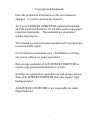
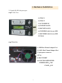
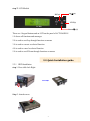
1
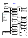
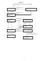
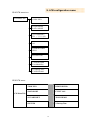
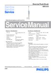
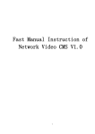
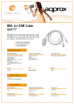
ACT-DASR101 Disk Array
Series products
Quick Installation Guide
VER:1.0
ACE-POWER COMPUTER TECHNOLOGY CORP
17F.-3, No.116, Zhengxin St., Zuoying Dist., Kaohsiung City 813, Taiwan (R.O.C.)
TEL:07-5575193
skype:avangel5193
FAX:07-5585192
E-mail:[email protected]
http://www.honetek.com/
1
Copyright and Trademark
Once the production information in this user manual is
changed,it won't be particularly noticed。
ACT is ACE-POWER COMPUTER registered trademark
and Microsoft and Windows are US Microsoft Corporation's
registered trademarks。The trademark are proprietors'
intellectual property。
This manual is protected under International Copyright Law
to remain all the rights。
No electrical or mechanical copy,distribution or writing
any words without our paper agreement。
Disk storage controller of ACE-POWER COMPUTER is
used to copy personal information or system。
It's illegal to against the Copyright Law and storage devices
from ACE-POWER COMPUTER date only support legal
backup purpose 。
ACE-POWER COMPUTER is not responsible for under
illegal behavior。
2
Table of contents
1.Introduction………………………………………………………….……...4
1.1.1
Introduction…………………………..…………..………….……..……..4
1.1.2
Specification.………………..…………..……….………….…….………4
1.1.3
ACT-DASR101 Series products…………………………………….…….5
2. Hardware Installation………………………………………………...6
2.1
Identify RAID Subsystem part…………………………………………….6
2.2
Quick Installation guide…………………………………………………...7
2.2.1 HDD Installation…………………………………………………..............7
3. Configure RAID Subsystems .………….…………………………8
3.1
Configuration methods……………………………………………………..8
3.1.1
Using LCD Module(LCM)………………………………………………...8
4.Connect ACT-DASR101 TO PC.……..…………………..…….......11
4.1 Connect ACT-DASR101 to pc…………………………………………….….11
4.2 Connect ACT-DASR101EE/EEU to pc………………………………............11
5.LCM configuration menu………………………..…………………...12
5.1
LCM menu tree……………………………………………………..............12
5.2
LCM menu……………………………………….……………..………......12
3
1. Introduction
1.1.1 Introduction
ACT-DASR101 is specifically for personal video/audio, editing storage and DVR Raid
storage applications. It allows easy scalability from JBOD to RAID, It can be
configured to RAID levels 0,1 and Smart Copy. The RAID function allows one HDD
failure without impact on the existing data and failed drive Data can be reconstructed
from the remaining data and parity drives. RAID configuration and monitoring can be
done through the LCM front control panel .
For ACT-DASR101,that is a internal platform. The RAID subsystem controller is
designed to fit in a two 5.25〞half-heigh drive bay for easy built-in the pc server.
For ACT-DASR101E series is a RAID tower platform, It features two 3.5inch SATAII
disk drives with RAID 0,1, Smart Copy .and connects to the host system through and
eSATA or USB/IEEE1394 interface.
For ACT-DASR101 series RAID subsystem, that is also a standard part of all major
operating systems such as xp/2000/2003 server, Mac, Linux, etc, the host system does
not require additional or proprietary software to work with the controller.
1.1.2 Specification
Host Interface
◎ one 3.0Gbps SATA port/one ATA 133 IDE port
※ Disk interface
◎ Two 3.0Gbps SATA ports(for 2.5〞/ 3.5〞HDD)
※ RAID Features
◎ RAID levels:0,1,Smart Copy
◎ HDD hot-swap
◎ Automatic online background data rebuilding
◎ Automatic disk failure detect
◎ Array roaming
◎ Rebuilding speed rata:250GB per hour(Max.)
※ Management
◎ Driverless: need no driver on host side
◎ LED indicators for Disk status display
◎ LCD control panel for operation status display
◎ RAID level configuration and selection by LCD panel
◎ NVRAM for event log and system configuration setting
※ Dimension: 210x 146 x 86mm
4
ACT-DASR101 Series products
Type
Model
Host Interface
ACT-DASR101
IDE/SATAII
ACT-DASR101EE
eSATA
LCD
Internal
Standard part
ACT-DASR101EU
USB2.0
ACT-DASR101EEU
eSATA/USB2.0
Tower
5
Raid Features
Two 3.0Gbps SATA
ports
(for 2.5〞/3.5〞HDD)
RAID levels:0,1, Smart
Copy
Supports more than 2TB
Bytes RAID drive
HDD hot-swap
Rebuilding speed:
250GB/hour
Supports Hot Spare on
RAID
Array roaming
Supports partial /
slumber power saving
mode
Supports on-line
command based bad
sector recovery
Supports staggered spinup
Support Device Status LEDs
(Error, Activity/Link)
2. Hardware Installation
2.1 Identify RAID Subsystem part
step1. Front View
(1) TRAY 1
(2) TRAY 2
(3) LCD MODULE
(4) TOP KEY-LOCK
(5) BOT KEY-LOCK
(6) TOP HDD Link & Access LED
(7) BOT HDD Link & Access LED
(8) Alarm
step 2.BackSide
(1) IDE Host Channel Adapter Port
(1)
(2)
(2) SATA Host Channel Adapter Port
(3) 4pin power connector
(4) Fan
(6)
(3)
(4)
(5) RS-232 PORT
(5)
(6)SATA TRANSFER SPEED
JUMPER OPEN:3.0G
CLOSE:1.5G
6
step 3. LCD Module
ESC(4)
Up(▲)(2)
ENT(3)
LCD(1)
Down(▼) (5)
There are 4 keypad buttons and an LCD on the panel of ACT-DASR101
1.It shows all functions and messages
2.It is used to scroll up through functions or menus
3.It is used to execute a selected function
4.It is used to cancel a selected function
5.It is used to scroll Down through functions or menus
2.2 Quick Installation guide
2.2.1 HDD Installation
step 1. Press slide lock Right
Step 2. Attach screws
7
step 3. Press tray handle on Sliding the tray with hard drive into the enclosure
step 4. Mounting RAID Subsystem in system
step 5. Connecting RAID Subsystem power
step 6. Connecting RAID Subsystem to Host channel (SATA/eSATA /USB2.0)
3. Configure RAID Subsystems
You can configure RAID Subsystem either through the LCD configuration utility.
3.1 Configuration methods
3.1.1 Using LCD Module(LCM)
The LCM is the primary user interface for the RAID subsystem, All configuration and
management of the controller and it’s properly connected disk arrays can be performed
from this interface.
The quick RAID setup flow chat is showed as following:
8
Power on
MENU 1
Utran V1.16
RAID 1
After Initial
Top:OK
Bot:OK
push ENTER key
push ESC key
Rebuilding
Rebuild OK
Rebuilding
X TO Y ZZ%
MAIN Page
EVENT LOG Format
1.T B REASON
YYYY/MM/DD HH/MM
TOP HDD
BOT HDD
REASON:
1.NO HDD
2.FAIL
3.BAD SECTOR
4.INSERT
5.REBUILD OK
push ENTER key
1.DISK INFO
push ESC key
Up key
T:HDD Model Cap
Serial Number
Down key
Down key
2.RAID MODE
RAID 1 MODE
Up key
B:HDD Model Cap
Serial Number
Up key
Down key
3.ENVORINMET
XX 。C Y Y Y Y R PM
Up key
Down key
4.BUZZER ON/OFF
ON
push ENTER key
push ESC key
Up key
ENTER key
Down key
push ENTER key
Up key
push ESC key
6.EVENT LOG
Up key
Down key
ENTER key
4.BUZZER ON/OFF
OFF
5.REBUILD PRIO
HIGH
Down key
4.BUZZER ON/OFF
ON
push ENTER key
push ESC key
5.REBUILD PRIO
HIGH
ENTER key
5.REBUILD PRIO
MIDDLE
ENTER key
7.TIME HH/MM
Year/Month/Day
5.REBUILD PRIO
LOW
Up key
Down key
1.EVENT
8.N Backup Time
Y/M/D HH:MM
Then in any menu, not pressed
any key within 10 seconds that
the return to the main screen.
Up key
Down key
Up key
Down key
10.EVENT
Up key
1.DISK INFO
Down key
1.EVENT
9
MENU 2
Push ENTER key for 3 second enter to set RAID
mode
RAID CINFIG
1.RAID 1
push ENTER key for 3
second
PLEASE SHOT DOWN
AND REBOOT
Down key
Up key
RAID CINFIG
2.RAID 0
push ENTER key for 3
second
Down key
Up key
push ENTER key
RAID CINFIG
2.RAID 0
push ESC key
YEAR/MONTH/DAY
YYYY/MM/DD SET
Down key
SET
ESC key
SET
Up key
HOUR/MINUTE
HH/MM
SET
push ENTER key
SMART COPY
push ESC key
COPY CYLCE
XDAY HH:MM SET
Down key
WHEN FALG AT SET
push ENTER key for3 second
Up key
RAID CINFIG
1.RAID 1
PLEASE SHOT DOWN
AND REBOOT
10
4. Connect ACT-DASR101 TO PC
4.1 Connect ACT-DASR101 to pc
1.Open the pc case, insert ACT-DASR101,and connect two 4-PIN power cords to make
ACT-DASR101 work well.
2.Connect a SATA cable to the SATA port of the system board.
3.Connect the other and of the SATA cable to ACT-DASR101.
4.Fasten with 12 screws, and close the pc case.
4.2 Connect ACT-DASR101EE/EEU to pc
1.Insert one end of the ESATA cable into the eSATA port of the pc system, and the other
end into the eSATA port of ACT-DASR101EE/EEU.
2.Connect the power cord.
Once installing successfully, you can find ACT-DASR101 as a non-initial Disk in
〝Disk manager〞under〝my computer〞and then to Format this Disk.
11
5. LCM configuration menu
5.1 LCM menu tree
LCM Menu Title
1.DISK INFO
2.RAID MODE
RAID 1 MODE
3.ENVORINMET
XX C Y Y Y Y R PM
4.BUZZER ON/OFF
ON
5.REBUILD PRIO
HIGH
6.EVENT LOG
7.TIME HH/MM
Year/Month/Day
8.N Backup Time
Y/M/D HH:MM
5.2 LCM menu
LCM Menu Title
1. DISK INFO
5. REBUILD PRIO
2. RAID MODE
6. EVENT LOG
3. ENVORINMET
7. TIME HH/MM
4. BUZZER
8. N Backup Time
12