1
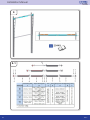
Installation Manual
Vertical Lift
Installation Manual
Contents
Symbols........................................................................................................................................................................................ 3
General warnings......................................................................................................................................................................... 3
Safety requirements for assembly and first use........................................................................................................................... 3
Terms and conditions................................................................................................................................................................... 3
Guidelines..................................................................................................................................................................................... 4
Fixing material to the construction............................................................................................................................................... 4
Trackset Assembly....................................................................................................................................................................... 4
Panel Assembly............................................................................................................................................................................ 5
System overview and build in requirements................................................................................................................................ 5
Application range......................................................................................................................................................................... 5
Notes............................................................................................................................................................................................ 6
Assembly...................................................................................................................................................................................... 7
First use...................................................................................................................................................................................... 29
Handover.................................................................................................................................................................................... 29
Electric operator (optional)......................................................................................................................................................... 29
Control unit settings................................................................................................................................................................... 29
Disassembly............................................................................................................................................................................... 29
Warnings.................................................................................................................................................................................... 29
Procedure................................................................................................................................................................................... 29
Disposal...................................................................................................................................................................................... 30
Maintenance............................................................................................................................................................................... 30
Warnings.................................................................................................................................................................................... 30
Replacement of Parts................................................................................................................................................................. 31
Supplier...................................................................................................................................................................................... 31
2
V 2.1
Vertical Lift
Symbols
Danger Sign: Important (safety) instructions
Hand Sign: Operation by hand
Information Sign, Indication Sign: Hint or Clue
Chain Hoist Sign: Operation by Chain Hoist
Book Sign: Additional manual
E. Operator Sign: Operation by Electric Operator
Eye Sign: Look to / Check
DPD Sign: Door Processing Document
General warnings
This manual has been prepared for use by qualified persons and therefore not by trainees or “do it yourselfers”.
The persons how assembly, disassembly, maintain or put the door system into operation need to careful read, understand
and follow this manual. To avoid severe personal injury, carefully read and observe all indications and warnings in this
manual.
•
•
•
•
•
•
This manual describes the assembly, disassembly and maintenance of your Industrial Door System; this may be supplemented by other manuals, for instance the spring break device manual, cable break device and operator manual (if applicable.)
The Industrial Door System has been designed in accordance with the latest European standards; however you have to check yourself whether this standard corresponds with the local national standard.
All measurements are in millimeters unless otherwise specified.
After installation ensure that the CE marking label has been completed and attached.
Keep this manual in a safe place, near to the Industrial door.
Subject to technical changes, without written notice.
Safety requirements for assembly and first use
• This Industrial Door System may only be mounted, connected and put into operation and maintained by qualified persons.
• Make sure that the power is switched off and remains switched off while electrical work is carried out!
• Never bridge safety devices!
• Adding or leaving out parts can affect the door operation in a negative way and therefore the safety of the installed sectional door. This is therefore strongly discouraged!
• Some parts can contain sharp edges: use protective gloves.
• All references to the door/component handing within this manual is always as viewed from inside looking out.
• Never use the Industrial Door System in case of a visual damage, especially cables and safety devices.
• When performing assembly/maintenance, always wear at least gloves and safety boots and during drilling/cutting wear safety goggles!
• Make sure that you can always perform your work in a stable environment.
• Secure the assembly/maintenance site with safety ribbon to keep others at a distance.
• Maintenance must only be performed by a qualified installation company and/or qualified persons.
• Make sure there is enough light.
• Only use appropriate tools, especially when tensioning the torsion springs.
Terms and conditions
Our general conditions of delivery and payments are applicable on all our offers, agreements or subsequent revisions.
A copy of our terms and conditions are available on request or can be downloaded from our website:
www.doco-international.com
V 2.1
3
Installation Manual
Guidelines
DOCO International had carried out the “Product Test“ of this door (Initial Type Testing = ITTr) by the SP institute in Sweden,
known as Notified Body No. 0402.
Documents regarding this ITTr can, in consultation with DOCO, be transferred to the company which produces the door.
This is necessary to complete the Technical File.
NOTE: CE-approved only using the correct DOCO-components.
It is the responsibility of the installation company to ensure that the chosen E-operator and panels are according to the
product standard EN13241-1 and have carried out the necessary ITTr.
If a wicket door is to be installed, it is the responsibility of the installation company to ensure that the complete door
conforms to the product standard EN13241-1 and have carried out the necessary ITT.
Fixing material to the construction
The necessary fixings to ensure the Industrial Door System to the building and/or ceiling, are not included!
It is the responsibility of the installation company to make sure that the building structure is safe/strong enough, to accept
the door and its fixings.
The installer is also responsible for using the correct fixing materials on the right foundation (stone, concrete, steel, wood).
In the image section there will be therefore no specification included.
Doorweight* for roofload: 510 N/m2
Using doorblads between 7-14 kg/m2
Trackset assembly
When you received a trackset kit you can skip this section.
When you build your own trackset follow next construction guideline:
Drilling:
Use M8 bolt (14010 or 14023) and nuts (14022 or 14013) every 650 mm (max.) between below connections,
predrill Ø8,5mm:
Vertical Trackset: connection between, Vertical Angle 290030-series and Track 22000-series.
Horizontal Trackset: connection between, Curve 215091-series and C-track 220016-series.
Connection between vertical angle 290030-series and connection brackets 235300 - 235307
Use 1 M8 bolts / nuts (as above) between track and connection bracket and 1 M8 bolts / nuts (as above) spread out
between Vertical angle and connection bracket.
More information see: Technical Production Book
Riveting:
Minimum rivet size: 5mm, every 650 mm (max.) between below connections.
Rivets need to fixed in accordance with the instructions / manual of the rivet equipment.
Vertical Trackset: connection between, Vertical Angle 290030-series and Track 22000-series.
Horizontal Trackset: connection between, Curve 215090-series and C-track 220016-series.
Connection between vertical angle 290030-series and connection brackets 235300 - 235307.
Use 1 rivet (as above) between track and connection bracket and 2 rivets (as above) spread out between Vertical angle and
connection bracket.
More information see: Technical Production Book
4
V 2.1
Vertical Lift
Panel assembly
The panels need to be assembled according the Industrial Panel Assembly Manual
System Overview and build in requirements
See Industrial Track Systems document for system drawings, build in requirements and required free running space of the
industrial door.
Application Range
This hardware set has been developed for commercial use
• Maximum width: 8500 mm
• Maximum height: 5500 mm ( 112021 = 6000mm)
• Maximum door leaf area: 48m2
• Weight door leaf maximum: 518 kg (112021 = 500kg)
• Maximum temperature range outside*: -20 ºC until +50 ºC
• Relative humidity: 5-90%
* Big differences in temperature between the inside and outside can cause deflection in the panel sections (bi-metal effect).
In particular dark colored panels are susceptible to this problem and should be avoided. Care should be taken during
manual handling as there is a big risk of damage.
V 2.1
5
Installation Manual
Notes:
6
V 2.1
Vertical Lift
V 2.1
7
Installation Manual
1
2
8
V 2.1
Vertical Lift
3
4
V 2.1
9
Installation Manual
5
5-1
10
V 2.1
Vertical Lift
5-2
5-3
Q = “140910” / 2
“140910”
V 2.1
11
Installation Manual
5-4
5-5
12
V 2.1
Vertical Lift
5-6
5-7
V 2.1
13
Installation Manual
6
7
- Panel assembly
- Paneele montage
- Panneaux montage
- Panel montanje
- Pannelli montaggio
- Montáž na Panel
- Montaż Panelu
- Paneel montage
14
V 2.1
Vertical Lift
7-1
7-2
V 2.1
15
Installation Manual
7-3
7-4
16
V 2.1
Vertical Lift
7-5
7-6
V 2.1
17
Installation Manual
8
8.1
18
V 2.1
Vertical Lift
8.2
8.3
V 2.1
19
Installation Manual
8.4
8.5
20
V 2.1
Vertical Lift
8.6
15
9
V 2.1
21
Installation Manual
9.1
9.2
22
V 2.1
Vertical Lift
10
11
V 2.1
23
Installation Manual
11.1
11.2
24
V 2.1
Vertical Lift
12
12.1
V 2.1
25
Installation Manual
12.2
-
13
-
26
V 2.1
Vertical Lift
14
15
V 2.1
27
Installation Manual
16
16.1
16-1
28
V 2.1
Vertical Lift
First use
The First use of the Industrial door System has to be carried out by the installer. After that the ALL users need to be
instructed. For more information check the User Manual.
Handover
Handover the following documents to the end user:
• This manual (assembly, maintenance and disassembly)
• User manual
• Service logbook
• Declaration of Performance (DoP)
• Declaration of Conformity (DoC), only in case of a Power operated door
Electric operator (optional)
Mount the operator according the supplier’s manual.
NOTE:
In case of power failure it should be possible to unlock the door using the emergency release from the operator. The door
leaf may only in that case, be operated with a handle. Do not fit a pull cord, shoot bolt or lock to an electrically operated
door, or the shootbolt or lock need to be equipped with a E-switch.
Control unit settings
Settings to the control unit should be carried out in accordance with the operator manufacturers manual.
Please note that our hardware kits have been CE approved for use with the operators specified in our ITTr report. Should a
different operator be chosen, then the installer must carry out a peak force analysis in accordance with EN-12445 and
EN-12453.
Disassembly
Disassembly should be only carried out by an qualified industrial door company / installer.
The door should be disassembled in the reverse sequence to the assembly manual.
Warnings
•
•
•
Brackets and other components which are attached to Torsion Springs and Cables are under extreme tension.
Tensioned springs carry a high tension; always be very careful, and make sure the tensioning bar (# 12025) are well maintained and use the right side of the bar (depends on used spring plug).
When checking the industrial door system, always disconnected the electrical main power supply and make sure that it is blocked against re-engaging without you knowing it.
Procedure:
1 Release tension of the torsion springs!
a) Insert the 1st tensioning bar into the tensioning head
b) Keep a good grip on the 1st tensioning bar and carefully undo the bolts on the tensioning head and transfer the spring
tension.
c) Now place the 2nd tensioning bar in the next hole of the spring plug and carefully release the spring. The spring is released from top to bottom.
d) Again, fit the 1st tensioning bar to the spring plug and release.
e) Repeat steps 3-4 until the spring is released.
f) Repeat steps 1-4 for the other spring (springs).
2 Remove the electrical operator, according the manual of the electrical operator
3 Release the bolts in the cable drums and remove the steel cables from the cable drums. Be careful for any remaining tension in the cables, check if the cables are slack!
4 Remove the power-unit. Do this by first removing the coupler and then carefully sliding both shaft halves out of the bearing plates. Be aware that components may slide along the shaft!
5 Remove the panel sections from top to bottom. Achieve this by removing the roller holders and centre hinges.
6 Remove the horizontal trackset
7 Remove the vertical trackset
V 2.1
29
Installation Manual
Disposal
All parts of this Industrial Door System can be easily disposed of.
Please consult your local authorities on this matter.
Maintenance
In accordance with EU standards, Industrial door systems should be maintained and checked regularly, from the first time of
use, based on the indicated service by the installer.
Maintenance needs to be recorded written.
Maintenance should be only carried out by an qualified industrial door company / installer.
Warnings
•
•
•
Brackets and other components which are attached to Torsion Springs and Cables are under extreme tension.
Tensioned springs carry a high tension; always be very careful, and make sure the tensioning bar (# 12025) are well maintained and use the right side of the bar (depends on used spring plug).
When checking the industrial door system, always disconned the electrial main power supply and make sure that it is blocked against re-engaging without you knowing it.
Directly after installation (By Installer):
1 Lubricate the running part of the tracks (advice: PTFE)
2 Lubricate bearings and the shaft of the rollers (advice: PTFE)
3 Lubricate pins of the hinges from intermediate- and side-hinges (advice: PTFE)
4 Lubricate the bearing of the shaft (advice: PTFE) 5 Lubricate sealing rubbers (advice: special rubber grease or vasaline)
After 3 months (By Installer):
1 Check balancing system / Re-tensioning springs (relaxation springs)
2 Complete visual inspection
Every 6 months (By User):
1 Check side seals, Top seal and Bottom Seal on damage or wear and tear
2 Lubricate the running part of the tracks (advice: PTFE)
3 Lubricate bearings and the shaft of the rollers (advice: PTFE)
4 Lubricate pins of the hinges from intermediate- and side-hinges (advice: PTFE spray)
5 Lubricate sealing rubbers (advice: special rubber grease or vasaline)
6 Clean the panels (advice: shampoo for car cleaning with water), do not use aggressive detergents
7 Wax the panels (advice: car wax)
8 Remove dirt from the door and surroundings
Every 12 months or every 7500 door cycles (By Installer):
1 Check the cables and the end connections from the cable on damages or wear and tear
2 Check the cable connection points on bottom bracket or cable break device and Cable drum
3 Check the spring break devices in accordance with separate manual
3.1 Check the position of the ratched wheel
3.2 Check the function of the catcher
3.3Check the bolt and screws connection of the SBD
4 Check the Cable Brack Device in accordance with the seperate manual
4.1 Check the function of the Cable Break Device
4.2 Check position of the knife of the Cable Break Device
4.3 Check the position of the hinge pin
5 Check the balance of the door and adjust if needed / check the manual operation
6 Check the hinges on breaking and wear and tear
7 Check the Pulley system (if present) for damages or wear and tear
8 Check or test the fixations of the springs to the spring plugs
9 Check the rollers or damages or wear and tear and free moving space
10 Check the closing forces of the main closing edge (Only if Electrical Operation an Not Deadman function)
11 Check the suspension from the horizontal track to the ceiling 11.1 Check the suspension profiles on breaking or damages
11.2 Check the bolt and nut connection
12 Check side seals, Top seal and Bottom Seal on damage or wear and tear
13 Check the panels on damage, wear and tear
14 Lubricate torsion springs, bearings of rollers, running parts of the track and bearing on the shaft
30
V 2.1
Vertical Lift
Every 24 months or every 15000 door cycles (By Installer):
1 Check the cables and the end connections from the cable on damages or wear and tear
2 Check the cable connection points on bottom bracket or cable break device and Cable drum
3 Check the spring break devices in accordance with separate manual
3.1Check the position of the ratched wheel
3.2 Check the function of the catcher
3.3 Check the bolt and screws connection of the SBD
4 Check the Cable Brack Device in accordance with the seperate manual
4.1 Check the function of the Cable Break Device
4.2 Check position of the knife of the Cable Break Device
4.3 Check the position of the hinge pin
5 Check the balance of the door and adjust if needed / check the manual operation
6 Check the hinges on breaking and wear and tear
7 Check the Pulley system (if present) for damages or wear and tear
8 Check or test the fixations of the springs to the spring plugs
9 Check the rollers or damages or wear and tear and free moving space
10 Check the closing forces of the main closing edge (Only if Electrical Operation an Not Deadman function)
11 Check the suspension from the horizontal track to the ceiling
11.1 Check the suspension profiles on breaking or damages
11.2 Check the bolt and nut connection
12 Check the shaft on damages and wear and tear
13 Check the connection of the trackset
14 Check and re-fix the bolt of the coupler
15 Check side seals, Top seal and Bottom Seal on damage or wear and tear
16 Check the panels on damage, wear and tear
17 Lubricate torsion springs, bearings of rollers, running parts of the track and bearing on the shaft
Replacements of Parts
Only use Original DOCO spare parts!
Maintenance should be only carried out by a qualified industrial door company / installer.
After Spring Break:
See instructions separate manual (or download the manual: www.doco-international.com)
1 Replace the springs and the Spring Break Device
2 Check the shaft on damages and replace if necessary
After Cable Break:
See instructions separate manual (or download the manual: www.doco-international.com)
1 Replace cable with connection
2 Replace the complete Cable Break Device
3 Check tracks and service or replace the tracks
Supplier
DOCO International b.v.
Nusterweg 96
6136 KV Sittard
P.O. Box 427
6130 AK Sittard
The Netherlands
Tel: +31 (0) 464200666
Fax: +31 (0) 46452894
www.doco-international.com
V 2.1
31
DOCO International B.V.
DOCO International Ltd.
Nusterweg 96
6136 KV Sittard
The Netherlands
Phone +31 464200666
Fax +31 464526894
[email protected]
Unit B3. Elvington Industrial Estate
Elvington
York
YO41 4AR
United Kingdom
Phone +44 1904607869
Fax +44 1904607299
[email protected]
DOCO International
Southern Europe S.L.U
Avenida Generalitat 55
P.I. “Can Met Sidru”
08530 La Garriga - Barcelona
Spain
Phone +34 938612825
Fax +34 938716592
[email protected]
DOCO International
Central Europe S.R.O.
Háj 352
798 12 Kralice na Hané
Czech Republic
Phone +420 582360100
Fax +420 582360300
[email protected]
A company of the SOMMER Group
For your Residential
and Industrial door solutions:
www.doco-international.com