1
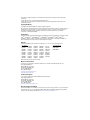
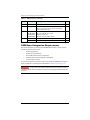
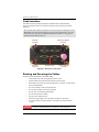
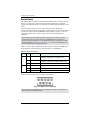
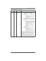
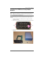
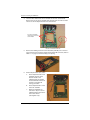
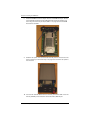
Universal
Development
Kit
Product
Name
GuideGuide
QuickUser
Reference
Part No. 875-0284-000
Rev E1
Part No.
This device complies with part 15 of the FCC Rules. Operation is subject to the following two
conditions:
(1) This device may not cause harmful interference, and
(2) this device must accept any interference received, including interference that may cause
undesired operation.
Copyright Notice
Copyright Hemisphere GNSS, Inc. (2013). All rights reserved.
No part of this manual may be reproduced, transmitted, transcribed, stored in a retrieval system or
translated into any language or computer language, in any form or by any means, electronic,
mechanical, magnetic, optical, chemical, manual or otherwise, without the prior written
permission of Hemisphere GNSS.
Trademarks
Hemisphere GPS®, the Hemisphere GPS logo, COASTTM, Crescent®, Earthworks®, EclipseTM, e-Dif®,
L-DifTM, miniEclipseTM, PocketMAX PCTM, PocketMAXTM, PocketMax3TM, S320TM, SBX-4TM,
SureTrack®, VectorTM, XF1TM, and XF2TM are proprietary trademarks of Hemisphere GNSS, Inc.
Other trademarks are the properties of their respective owners.
Patents
Hemisphere GNSS products may be covered by one or more of the following patents:
U.S. Patents
6111549
6876920
6397147
7142956
6469663
7162348
6501346
7277792
6539303
7292185
6549091
7292186
6711501
7373231
6744404
7388539
6865465
7400294
7400956
7429952
7437230
7460942
7689354
7808428
7835832
7885745
7948769
8000381
8018376
8085196
8102325
8138970
8140223
8174437
8184050
8190337
8214111
8217833
8265826
8271194
8307535
8311696
8334804
RE41358
Australia Patents
2002244539
2002325645
2004320401
Other U.S. and foreign patents pending.
Notice to Customers
Contact your local dealer for technical assistance. To find the authorized dealer near you:
Hemisphere GNSS, Inc.
8444 N 90th St, Suite 120
Scottsdale, AZ 85258 USA
Phone: (480) 348-9919
Fax: (480) 348-6370
[email protected]
www.hemispheregps.com
Technical Support
If you need to contact Hemisphere GNSS Technical Support:
Hemisphere GNSS, Inc.
8444 N 90th St, Suite 120
Scottsdale, AZ 85258 USA
Phone: (480) 348-9919
Fax: (480) 348-6370
[email protected]
Documentation Feedback
Hemisphere GNSS is committed to the quality and continuous improvement of our products and
services. We urge you to provide Hemisphere GNSS with any feedback regarding this guide by
writing to the following email address: [email protected].
Contents
Chapter 1
Universal Development Kit Overview . . . . . . . . . . . 1
What is the Universal Development Kit? . . . . . . . . . . . . . . . . . . . . . 2
Supported OEM Boards . . . . . . . . . . . . . . . . . . . . . . . . . . . . . . . . . . . 2
Supporting Documentation . . . . . . . . . . . . . . . . . . . . . . . . . . . . . . . . 2
UDK Components . . . . . . . . . . . . . . . . . . . . . . . . . . . . . . . . . . . . . . . 3
OEM Board Integration Requirements . . . . . . . . . . . . . . . . . . . . . . . 4
Chapter 2
Kit Specifications . . . . . . . . . . . . . . . . . . . . . . . . . . 5
Cable Interface . . . . . . . . . . . . . . . . . . . . . . . . . . . . . . . . . . . . . . . . . . 6
Routing and Securing the Cables . . . . . . . . . . . . . . . . . . . . . . . . . . . 6
Environmental Requirements . . . . . . . . . . . . . . . . . . . . . . . . . . . . . . 7
Powering the UDK . . . . . . . . . . . . . . . . . . . . . . . . . . . . . . . . . . . . . . . 7
Serial Ports . . . . . . . . . . . . . . . . . . . . . . . . . . . . . . . . . . . . . . . . . . . . . 8
USB Ports . . . . . . . . . . . . . . . . . . . . . . . . . . . . . . . . . . . . . . . . . . . . . . 9
LED Indicators . . . . . . . . . . . . . . . . . . . . . . . . . . . . . . . . . . . . . . . . . . 9
Chapter 3
Installing an OEM Board . . . . . . . . . . . . . . . . . . . . 13
Using an Adapter Board . . . . . . . . . . . . . . . . . . . . . . . . . . . . . . . . . 14
Installing Your OEM Board - No Adapter Board Required . . . . . . 16
Installing Your OEM Board Using Adapter Board A or B . . . . . . . 20
Installing Your OEM Board Using Adapter Board C . . . . . . . . . . . 25
Installing Your OEM Board Using Adapter Board D . . . . . . . . . . . 29
Index . . . . . . . . . . . . . . . . . . . . . . . . . . . . . . . . . . . . . . . . . . . . . . . 35
End User License Agreement . . . . . . . . . . . . . . . . . . . . . . . . . . . . 37
Warranty Notice . . . . . . . . . . . . . . . . . . . . . . . . . . . . . . . . . . . . . . 40
Universal Development Kit User Guide
iii
PN 875-0284-000 Rev E1
Chapter 1: Universal Development Kit
Overview
What is the Universal Development Kit?
Supported OEM Boards
Supporting Documentation
UDK Components
OEM Board Integration Requirements
Universal Development Kit User Guide
1
PN 875-0284-000 Rev E1
Chapter 1: Universal Development Kit Overview
This user guide provides detailed information on the interface and workings of the
Universal Development Kit, its specifications, and how to connect a Hemisphere GPS
OEM board to the Universal Development Kit.
This user guide does not cover receiver operation, the PocketMax™ utility, or
commands and messages (NMEA 0183, NMEA2000® or HGPS proprietary). For
information on these subjects refer to the Hemisphere GPS Technical Reference (go to
www.hemispheregps.com and click the GPS Reference icon).
What is the Universal Development Kit?
The Universal Development Kit allows you to integrate a Hemisphere GPS OEM board
into your design and includes the following:
•
Enclosure
•
Main carrier board
•
Set of four adapter boards for use with small form factor Hemisphere GPS
OEM boards
•
Power cable and AC power supply
•
Two serial cables - one straight serial cable and one null modem cable for
RTK
Note: Throughout the rest of this user guide, the Universal Development Kit is
referred to simply as the UDK.
Supported OEM Boards
The UDK supports the following Hemisphere GPS OEM boards:
•
Crescent®
•
Crescent Vector™ II
•
Eclipse™
•
Eclipse Vector™
•
LX-2™ (L-band DGPS service, L-band high precision services, L-band high
precision service with GLONASS)
See Table 3-1 on page 15 for a list of specific OEM board models the UDK supports.
Supporting Documentation
For the Hemisphere GPS OEM board you purchase with the UDK there is an Integrator
Guide available for download from the Hemisphere GPS website at
www.hemispheregps.com.
Universal Development Kit User Guide
2
PN 875-0284-000 Rev E1
Chapter 1: Universal Development Kit Overview
UDK Components
Figure 1-1 shows the parts included in the UDK and Table 1-1 provides part numbers
and descriptions.
Note: The UDK does not include an antenna or antenna cable; they are available
from Hemisphere GPS as accessory items.
A
B
C
F
E
D
G
H
Figure 1-1: UDK components
Table 1-1: UDK parts list
Item
Part No.
Description
Qty
A
802-1066-000#
Enclosure (includes outer enclosure, front and rear
panels, main carrier board, RF cable)
1
B
725-1293-000#
Adapter boards (set of 4: Boards A, B, C, D)
1
Note: Two additional adapter boards (E and F) are
included with Board D and act as spacer boards.
C
051-0172-000#
Serial data cable, DB9 male - DB9 male, 3 m
1
D
054-0009-000#
Power cable, 3 m
1
Universal Development Kit User Guide
3
PN 875-0284-000 Rev E1
Chapter 1: Universal Development Kit Overview
Table 1-1: UDK parts list (continued)
Item
Part No.
Description
Qty
E
050-0011-022#
Serial I/O cable, DB9 female - DB9 male, 3 m
1
F
053-0046-000#
RF cable, TNC female - MCX male, 280 mm
1
Note: For use with Crescent Vector II and Eclipse
Vector OEM boards only.
G
675-0002-004#
676-1007-000#
678-0003-001#
680-0007-000#
Machine screw, 4-40, 1/4", PPHC, SS
Nut, hex, 4-40, SS, nylon insert
Washer, lock, #4, SS
Standoff, hex, M-F, 4-40, 5/16”, SS
8
8
8
12
H
427-0030-000#
AC adapter
1
054-0084-000#
AC cable, 2 m
1
OEM Board Integration Requirements
Successful integration of a Hemisphere GPS OEM board within a system requires
electronics expertise that includes:
•
Power supply design
•
Serial port level translation
•
Reasonable radio frequency competency
•
Understanding of electromagnetic compatibility
•
Circuit design and layout
For general integration requirements refer to the appropriate OEM Board Integrator
Guide available from the Hemisphere GPS website at www.hemispheregps.com.
You may open and operate the UDK without the enclosure; however,
use ESD protection when opening the enclosure and operating the UDK without the
enclosure.
Universal Development Kit User Guide
4
PN 875-0284-000 Rev E1
Chapter 2: Kit Specifications
Cable Interface
Routing and Securing the Cables
Environmental Requirements
Powering the UDK
Serial Ports
USB Ports
LED Indicators
Universal Development Kit User Guide
5
PN 875-0284-000 Rev E1
Chapter 2: Kit Specifications
Cable Interface
The UDK enclosure provides power, data, and GPS antenna cable interfaces.
Figure 2-1 shows the various connections located on the rear panel of the UDK
enclosure.
Note: The Secondary GPS RF connection is for Crescent Vector II and Eclipse Vector
OEM boards only, both of which allow for the use of two GPS antennas. You must
connect this port using the provided TNC cable (Part F in Table 1-1 on page 3) to
enable the functionality of this port.
DC power
connector
AC power
connector
Secondary GPS RF
connector
Serial ports (4)
Primary GPS RF
connector
Figure 2-1: Rear panel connections
Routing and Securing the Cables
Consider the following when routing UDK cables:
•
Power cable must reach an appropriate power source
•
Antenna cable must reach from the antenna to the receiver
•
Data cable may connect to a data storage device, computer, or other device
that accepts GPS data
•
Do not run cables in areas of excessive heat
•
Do not expose cables to corrosive chemicals
•
Do not crimp or excessively bend cables
•
Do not place tension on cables
•
Coil up excess cable near unit
•
Secure along the cable route using plastic tie wraps as necessary
•
Do not run cables near high voltage or strong RF noise and transmitter
sources
Improperly installed cables near machinery can be dangerous.
Universal Development Kit User Guide
6
PN 875-0284-000 Rev E1
Chapter 2: Kit Specifications
Environmental Requirements
The UDK is designed to be stored and operated between -40°C and +85°C (-40°F and
+185°F). The optional Hemisphere GPS antennas available for the UDK are designed
to operate in an outdoor environment and are waterproof.
Note: Refer to the OEM board Integrator Guide for environmental requirements for
your OEM board.
Powering the UDK
The UDK accepts from 5 to 18 VDC and the supplied power should be continuous and
clean for best performance. The UDK will start when an acceptable voltage is applied.
Do not apply a voltage higher than 18 VDC. This will damage the
receiver and void the warranty.
You can power the UDK in either of the following ways:
•
Connect the DC power cable to a suitable power source
a.
Connect the red wire of the cable’s power input to DC positive (+).
b.
Connect the black wire of the cable’s power input to DC negative (-).
Note: A 1.0 A fast-blow fuse is equipped and situated in-line of the power
input of the power cable and protects the UDK from power surges. The
fuse container should remain accessible after installation.
Do not operate the UDK with the fuse bypassed. This will
void the product warranty.
•
Connect the AC power adapter to the UDK
If the OEM board does not power on, make sure the internal power switch on the
carrier board is in the “ON” position (see Figure 2-2).
Figure 2-2: Carrier board ON/OFF switch
Connecting more than one source of power at a time can seriously
damage the unit and will void the warranty.
Universal Development Kit User Guide
7
PN 875-0284-000 Rev E1
Chapter 2: Kit Specifications
Serial Ports
The UDK provides four RS-232 compatible serial ports (located on the rear panel, see
Figure 2-1 on page 6) for communicating with external data loggers, navigation
systems, PCs, and other devices. The serial ports are labeled Port A, Port B, Port C, and
Port D.
Ports A, B and/or C may be used for communication. Port D is designed to
communicate with Hemisphere GPS’ SBX-4™ DGPS beacon receiver to receive DGPS
corrections and only operates at 9600 baud with an 8 data bit, no parity, 1 stop bit
configuration (8-N-1). Ports A, B or C may also receive external DGPS or RTK
corrections.
Note: The baud rate of the UDK’s serial ports and the devices they are trying to
communicate with must match. Refer to your OEM board’s documentation to
determine the default baud rate of your OEM board. Refer to the Hemisphere GPS
Technical Reference (go to www.hemispheregps.com and click the GPS Reference
icon) for information on changing baud rates.
Table 2-1 provides the pin assignments for the serial ports. Refer to your OEM board
documentation for communication protocols specific to your OEM board.
Table 2-1: Serial port pinouts
Port
Pin
Signal
Description
A,B,C
2
TXD
NMEA 0183, Hemisphere GPS proprietary binary,
RTCM v2.3 (DGPS), RTK v3, and CMR output
3
RXD
NMEA 0183, Hemisphere GPS proprietary binary,
RTCM v2.3 (DGPS), RTK v3, CMR, and CMR+ input
5
Signal ground
Signal return
2
TXD
Hemisphere GPS proprietary
D
3
RXD
RTCM input
4
Signal ground
Signal return
Figure 2-3 shows the pinout of each serial port of the UDK.
Figure 2-3: DB-9 socket numbering
Note: Hemisphere GPS OEM boards use a CMOS level interface. The UDK carrier
board converts from CMOS to RS-232.
Universal Development Kit User Guide
8
PN 875-0284-000 Rev E1
Chapter 2: Kit Specifications
USB Ports
The front panel of the UDK has ports for a USB client (device) and a USB host (see
Figure 2-5). Refer to your OEM board’s documentation for information on USB
functionality available for your OEM board.
LED Indicators
The UDK carrier board features surface-mounted diagnostic LEDs that indicate OEM
board status (see Figure 2-4). You can view the LEDs via the front panel of the UDK
enclosure, shown in Figure 2-5.
Figure 2-4: LEDs on the carrier board
Figure 2-5: LED indicators on UDK front panel
Table 2-2 describes the functionality of each LED.
Table 2-2: LED indicators
LED
Color
Function
Description
POWER
Red
Power
indicator
Illuminates when the OEM board is powered on.
RESET
Green
Reset indicator
Illuminates when you press the Reset button and
also flashes on powerup.
Reset
button
Note: Since the Reset button is inside the UDK
enclosure, use ESD protection when opening the
enclosure.
Universal Development Kit User Guide
9
PN 875-0284-000 Rev E1
Chapter 2: Kit Specifications
Table 2-2: LED indicators (continued)
LED
Color
Function
Description
1 PPS
Blue
Timing signal
(1 PPS)
Flashes once per second once a GPS signal lock is
obtained.
MARK
Red
Mark indicator
Illuminates when you press the Mark button
(manual mark). Pins 1 and 2 of JP300 (marked
‘Pushbutton’) require a jumper to enable the Mark
button.
Mark button
Pushbutton
Note: Since the Mark button is inside the UDK
enclosure, use ESD protection when opening the
enclosure.
GPS
Yellow
Primary GPS
lock indicator
Illuminates when the OEM board achieves a valid
position solution. If this LED continues to flash, it
could indicate receiver or antenna hardware
failure.
S-GPS
Yellow
Not used (always off)
A-GPS
Yellow
Not used (always off)
DIFF
Yellow
Differential
lock indicator
Illuminates when the OEM board:
•
Achieves solid SBAS or L-band lock with
better than a 150 bit error rate (BER)—if the
SBAS BER is higher than 150, but the
receiver is still locked, this LED will flash,
indicating marginal lock
•
Receives external DGPS RTCM corrections
•
Receives L-band DGPS corrections
•
Receives RTK corrections in any acceptable
correction format
Note: Not all differential corrections are available
on all Hemisphere GPS OEM boards. See your
OEM board documentation for details.
Universal Development Kit User Guide
10
PN 875-0284-000 Rev E1
Chapter 2: Kit Specifications
Table 2-2: LED indicators (continued)
LED
Color
Function
Description
DGPS
Green
DGPS position
indicator
Illuminates to indicate high accuracy positioning
•
For SBAS, DGPS or L-band DGPS
positioning solutions, the LED appears as
follows:
–
•
SOLID if position solution accuracy
estimate is below the $JLIMIT
command setting
For L-band DGPS, L-band high precision,
and L-band high precision with GLONASS
positioning solutions, the LED appears as
follows:
•
–
SOLID if position accuracy estimate
is below the $JLIMIT command
setting, and current GGA message
quality indicator is 4 or 5
–
FLASHES if accuracy is above
$JLIMIT setting, or GGA quality
indicator is 2
For RTK positioning solutions, the LED
appears as follows:
–
SOLID if current GGA message
quality indicator is 4
–
FLASHES if current GGA message
quality indicator is 2 or 5
Note: Not all differential corrections are available
on all Hemisphere GPS OEM boards. Some
differential corrections require a paid subscription.
An OEM board, such as the LX-2, is required for
L-band positioning solutions. A UHF radio is
necessary to receive some differential corrections.
See your OEM board documentation for details.
Universal Development Kit User Guide
11
PN 875-0284-000 Rev E1
Chapter 2: Kit Specifications
Table 2-2: LED indicators (continued)
LED
Color
Function
Description
HDG
Blue
Heading lock
indicator
Only in use for Crescent Vector II and Eclipse
Vector OEM boards
Illuminates continuously when the Crescent
Vector II OEM board or Eclipse Vector OEM board
has achieved a solid heading lock. Blinking on and
off repeatedly may indicate receiver hardware
failure.
Note: You must install a jumper (included in your
kit) on JP100 (Vector Receiver LED Enable) to
enable heading LED functionality.
Universal Development Kit User Guide
12
PN 875-0284-000 Rev E1
Chapter 3: Installing an OEM Board
Using an Adapter Board
Installing Your OEM Board - No Adapter Board Required
Installing Your OEM Board Using Adapter Board A or B
Installing Your OEM Board Using Adapter Board C
Installing Your OEM Board Using Adapter Board D
Universal Development Kit User Guide
13
PN 875-0284-000 Rev E1
Chapter 3: Installing an OEM Board
Using an Adapter Board
The UDK includes four adapter boards: Boards A, B, C, and D. The UDK also includes
two spacer boards (Boards E and F) that are used in conjunction (and only) with
Board D.
You can identify the type of adapter board in either of two ways (see Figure 3-1):
•
Designation on the board itself (‘Board A’ or ‘Board B’ or ‘Board C’ or ‘Board
D’ is imprinted on the board)
•
Number of pins in, and location of, the header connector:
–
Board A has a 34-pin header along the short edge of the board
–
Board B has a 20-pin header along the short edge of the board
–
Boards C and D have a 34-pin header along the long edge of the board
34-pin header
20-pin header
34-pin header
Board D is a main adapter
board (an OEM board
connects directly to it), while
Boards E and F are spacer
boards for appropriate
clearance. All three boards
are required when installing
the corresponding OEM
board as outlined in Table 3-1
on page 15.
34-pin header
Figure 3-1: Board A, B, C, and D indicators
Universal Development Kit User Guide
14
PN 875-0284-000 Rev E1
Chapter 3: Installing an OEM Board
If you are integrating with a large form factor board, such as the Eclipse II, you do not
need an adapter board. However, if you are integrating with a small form factor board,
such as the Crescent or miniEclipse, use Table 3-1 to determine which adapter board
you will need for your OEM board.
Table 3-1: OEM boards and associated adapter boards
OEM Board Family
OEM Board
Model
Board
A
Board
B
Board
C
Crescent
P100, P102, P104
Crescent
P101, P103
Crescent Vector II
H101
X
Eclipse Vector
H200
X
Eclipse Vector
H320
miniEclipse
P200, P202,
P300, P302
miniEclipse
P201, P203,
P301, P303
LX-2
(requires Crescent or miniEclipse
board that uses Board A)
N/A
Universal Development Kit User Guide
Board
D
X
X
X
X
X
X
15
PN 875-0284-000 Rev E1
Chapter 3: Installing an OEM Board
Installing Your OEM Board - No Adapter Board
Required
Caution: Use electrostatic discharge (ESD) protection, such as by wearing an
ESD strap that is attached to an earth ground, before handling the UDK or any
OEM boards. If an ESD strap is not available touch a metal object prior to
handling the UDK or any OEM boards.
Complete the following steps to install your OEM board where no adapter board is
required (such as with the Eclipse II board).
1.
Unpack your UDK. Refer to “UDK Components” on page 3 for the parts
included in your UDK.
2.
Remove the four screws from the corners of the rear panel of the enclosure.
Screws
3.
Screws
Slowly remove the rear panel and attached main carrier board from the
enclosure.
Universal Development Kit User Guide
16
PN 875-0284-000 Rev E1
Chapter 3: Installing an OEM Board
4.
There are two stacked sets of four standoffs on the main carrier board.
Remove the top set of four standoffs and set them aside. You will use them
later to secure the OEM board to the carrier board.
One set of standoffs
remaining on the main
carrier board
One set of standoffs removed
5.
Connect the free end of the TNC cable to your OEM board (make sure one
end is already connected to the main carrier board).
6.
Place the OEM board on the standoffs so the pin header on the OEM board
faces downward and fits into the mating pin header on the main carrier
Universal Development Kit User Guide
17
PN 875-0284-000 Rev E1
Chapter 3: Installing an OEM Board
board, and then attach the standoffs you removed in step 4 to secure the
OEM board to the main carrier board (hand-tighten only).
7.
Slide the rear panel / main carrier board assembly into the enclosure and use
the four screws you removed in step 2 on page 16 to secure the rear panel to
the enclosure.
8.
Connect an external GPS antenna to the Primary GPS RF port on the rear
panel.
9.
Connect the serial cable to Port A on the rear panel and to a serial port on
your PC.
Universal Development Kit User Guide
18
PN 875-0284-000 Rev E1
Chapter 3: Installing an OEM Board
10. Connect the power cable to a power port on the rear panel and to an external
power source. See “Powering the UDK” on page 7 for information on using
AC or DC power for the UDK.
11.
Power on the UDK.
12. Run PocketMax or SLXMon™ for development and diagnostic testing.
PocketMax and SLXMon are Hemisphere GPS products and both are
available for download from the Hemisphere GPS website at
www.hemispheregps.com.
Universal Development Kit User Guide
19
PN 875-0284-000 Rev E1
Chapter 3: Installing an OEM Board
Installing Your OEM Board Using Adapter
Board A or B
Caution: Use electrostatic discharge (ESD) protection, such as by wearing an
ESD strap that is attached to an earth ground, before handling the UDK or any
OEM boards. If an ESD strap is not available touch a metal object prior to
handling the UDK or any OEM boards.
Note: This procedure applies to installing one OEM board or two OEM boards. A two
OEM board configuration refers to installing an OEM board with the LX-2 board.
Refer to Table 3-1 on page 15 for which OEM boards are compatible with the LX-2
board.
Complete the following steps to install your OEM board where an adapter board
(Board A or B) is required. Refer to Table 3-1 on page 15 to determine the adapter
board required for your OEM board.
1.
Unpack your UDK. Refer to “UDK Components” on page 3 for the parts
included in your UDK.
2.
Remove the four screws from the corners of the rear panel of the enclosure.
Screws
3.
Screws
Slowly remove the rear panel and attached main carrier board from the
enclosure.
Universal Development Kit User Guide
20
PN 875-0284-000 Rev E1
Chapter 3: Installing an OEM Board
4.
There are two stacked sets of four standoffs on the main carrier board.
Remove the top set of four standoffs and set them aside. You will use them
later to secure the adapter board to the carrier board.
One set of
standoffs
remaining on the
main carrier board
One set of
standoffs
removed
Note: If you will be installing an LX-2 board, you must install the LX-2 board
first and then install the required OEM board on top of it. Proceed to step 5.
If you are not installing an LX-2 board, you will only install your OEM board.
Proceed to step 6.
5.
Using the nuts, washers, and standoffs from part G (see Table 1-1 on
page 3):
a.
Attach four standoffs to the adapter board, securing them from the
underside of the board with the nuts and washers (Figure A below).
b.
Attach the LX-2 board to the adapter board so the LX-2 board’s pin
header faces downward and fits into the adapter board’s mating pin
header and secure the LX-2 board with four standoffs (Figure B below).
c.
Attach the OEM board to the LX-2 board so the OEM board’s pin header
faces downward and fits into the LX-2 board’s mating pin header and
secure the OEM board with four standoffs (Figure C below).
A
B
C
Universal Development Kit User Guide
21
PN 875-0284-000 Rev E1
Chapter 3: Installing an OEM Board
6.
Using the nuts, washers, and standoffs from part G (see Table 1-1 on
page 3):
a.
Attach four standoffs to the adapter board, securing them from the
underside of the board with the nuts and washers (Figure A below).
b.
Attach the OEM board to the adapter board so the OEM board’s pin
header faces downward and fits into the adapter board’s mating pin
header and secure the OEM board with four standoffs (Figure B below).
A
7.
B
Connect the free end of the TNC cable to your OEM board (make sure one
end is already connected to the main carrier board).
Note: If you installed the LX-2 board in step 5, you will connect the free end
of the TNC cable to the LX-2 board.
8.
Place the adapter board on the standoffs so the adapter board’s pin header
faces downward and fits into the main carrier board’s mating pin header, and
Universal Development Kit User Guide
22
PN 875-0284-000 Rev E1
Chapter 3: Installing an OEM Board
then attach the standoffs you removed in step 4 to secure the adapter board
to the main carrier board (hand-tighten only).
One OEM board attached
to adapter board
9.
Two OEM boards attached
to adapter board
Slide the rear panel / main carrier board assembly into the enclosure and use
the four screws you removed in step 2 on page 20 to secure the rear panel to
the enclosure.
10. Connect an external GPS antenna to the Primary GPS RF port on the rear
panel.
11.
Connect the serial cable to Port A on the rear panel and to a serial port on
your PC.
12. Connect the power cable to a power port on the rear panel and to an external
power source. See “Powering the UDK” on page 7 for information on using
AC or DC power for the UDK.
Universal Development Kit User Guide
23
PN 875-0284-000 Rev E1
Chapter 3: Installing an OEM Board
13. Power on the UDK.
14. Run PocketMax or SLXMon for development and diagnostic testing.
PocketMax and SLXMon are Hemisphere GPS products and both are
available for download from the Hemisphere GPS website at
www.hemispheregps.com.
Universal Development Kit User Guide
24
PN 875-0284-000 Rev E1
Chapter 3: Installing an OEM Board
Installing Your OEM Board Using Adapter
Board C
Caution: Use electrostatic discharge (ESD) protection, such as by wearing an
ESD strap that is attached to an earth ground, before handling the UDK or any
OEM boards. If an ESD strap is not available touch a metal object prior to
handling the UDK or any OEM boards.
Complete the following steps to install your OEM board where adapter board C is
required.
1.
Unpack your UDK. Refer to “UDK Components” on page 3 for the parts
included in your UDK.
2.
Remove the four screws from the corners of the rear panel of the enclosure.
Screws
3.
Screws
Slowly remove the rear panel and attached main carrier board from the
enclosure.
Universal Development Kit User Guide
25
PN 875-0284-000 Rev E1
Chapter 3: Installing an OEM Board
4.
There are two stacked sets of four standoffs on the main carrier board.
Remove the top set of four standoffs and set them aside. You will use them
later to secure the adapter board to the carrier board.
One set of standoffs
remaining on the main
carrier board
One set of standoffs removed
5.
Remove the rubber grommet from the Secondary GPS RF port on the rear
panel of the enclosure and then attach the standalone RF connector (Part F in
Table 1-1 on page 3) to the Secondary port opening.
6.
Place the adapter board on the standoffs so the adapter board’s pin header
faces downward and fits into the main carrier board’s mating pin header, and
then attach the standoffs you removed in step 4 to secure the adapter board
to the main carrier board (hand-tighten only).
Universal Development Kit User Guide
26
PN 875-0284-000 Rev E1
Chapter 3: Installing an OEM Board
7.
Connect the free end of each TNC cable to your OEM board as shown below.
8.
Attach the OEM board to the adapter board so the OEM board’s pin header
faces downward and fits into the adapter board’s mating pin header, and
then using standoffs from part G (see Table 1-1 on page 3) secure the OEM
board to the standoffs (hand-tighten only).
Universal Development Kit User Guide
27
PN 875-0284-000 Rev E1
Chapter 3: Installing an OEM Board
9.
Slide the rear panel / main carrier board assembly into the enclosure and use
the four screws you removed in step 2 on page 25 to secure the rear panel to
the enclosure.
10. Connect two external GPS antennas to the rear panel of the UDK: one to the
Primary GPS RF port and the other to the Secondary GPS RF port.
11.
Connect the serial cable to Port A on the rear panel and to a serial port on
your PC.
12. Connect the power cable to a power port on the rear panel and to an external
power source. See “Powering the UDK” on page 7 for information on using
AC or DC power for the UDK.
13. Power on the UDK.
14. Run PocketMax or SLXMon for development and diagnostic testing.
PocketMax and SLXMon are Hemisphere GPS products and both are
available for download from the Hemisphere GPS website at
www.hemispheregps.com.
Universal Development Kit User Guide
28
PN 875-0284-000 Rev E1
Chapter 3: Installing an OEM Board
Installing Your OEM Board Using Adapter
Board D
Caution: Use electrostatic discharge (ESD) protection, such as by wearing an
ESD strap that is attached to an earth ground, before handling the UDK or any
OEM boards. If an ESD strap is not available touch a metal object prior to
handling the UDK or any OEM boards.
Complete the following steps to install your OEM board where adapter board D is
required.
1.
Unpack your UDK. Refer to “UDK Components” on page 3 for the parts
included in your UDK.
2.
Remove the four screws from the corners of the rear panel of the enclosure.
Screws
3.
Screws
Slowly remove the rear panel and attached main carrier board from the
enclosure.
Universal Development Kit User Guide
29
PN 875-0284-000 Rev E1
Chapter 3: Installing an OEM Board
4.
There are two stacked sets of four standoffs on the main carrier board.
Remove the top set of four standoffs and set them aside. You will use them
later to secure the adapter board to the carrier board.
One set of standoffs
remaining on the main
carrier board
One set of standoffs removed
5.
Remove the rubber grommet from the Secondary GPS RF port on the rear
panel of the enclosure and then attach the standalone RF connector (Part F in
Table 1-1 on page 3) to the Secondary port opening.
6.
Attach adapter boards D, E, and F:
a.
Place adapter board E on the
standoffs near the carrier
board’s header so the
adapter board’s pin header
faces downward and fits into
the main carrier board’s
mating pin header.
b.
Place adapter board F on the
other two standoffs.
c.
Attach the standoffs you
removed in step 4 to secure
adapter boards E and F to the
main carrier board
(hand-tighten only).
Universal Development Kit User Guide
30
PN 875-0284-000 Rev E1
Chapter 3: Installing an OEM Board
7.
d.
Attach four standoffs and screws from part G (see Table 1-1 on page 3)
to the four outer holes of adapter board D. Make sure the standoffs are
on the side of the board with the connector (J800) on the long side of
the board.
e.
Place adapter board D on the standoffs above adapter boards E and F
so adapter board D’s pin header faces downward and fits into adapter
board E’s mating pin header, and then secure adapter board D with four
nuts and four washers from part G (see Table 1-1 on page 3).
Connect the free end of each TNC cable to your OEM board as shown below.
Universal Development Kit User Guide
31
PN 875-0284-000 Rev E1
Chapter 3: Installing an OEM Board
8.
Attach the OEM board to the adapter board so the OEM board’s pin header
faces downward and fits into the adapter board’s mating pin header, and
then using the nuts from part G (see Table 1-1 on page 3) secure the OEM
board to the standoffs.
9.
Slide the rear panel / main carrier board assembly into the enclosure and use
the four screws you removed in step 2 on page 29 to secure the rear panel to
the enclosure.
10. Connect two external GPS antennas to the rear panel of the UDK: one to the
Primary GPS RF port and the other to the Secondary GPS RF port.
Universal Development Kit User Guide
32
PN 875-0284-000 Rev E1
Chapter 3: Installing an OEM Board
11.
Connect the serial cable to Port A on the rear panel and to a serial port on
your PC.
12. Connect the power cable to a power port on the rear panel and to an external
power source. See “Powering the UDK” on page 7 for information on using
AC or DC power for the UDK.
13. Power on the UDK.
14. Run PocketMax or SLXMon for development and diagnostic testing.
PocketMax and SLXMon are Hemisphere GPS products and both are
available for download from the Hemisphere GPS website at
www.hemispheregps.com.
Universal Development Kit User Guide
33
PN 875-0284-000 Rev E1
Index
Numerics
I
1 PPS LED 10
installing
OEM with adapter board A or B
20
A
OEM with adapter board C 25
OEM with adapter board D 29
OEM with no adapter board 16
integration 4
AC power adapter 4, 7
adapter boards
associated OEM boards 15
Boards A, B, C, and D 14
using 14
A-GPS LED 10
L
LED indicators 9
1 PPS 10
A-GPS 10
DGPS 11
Diff 10
GPS 10
HDG 12
MARK 10
POWER 9
RESET 9
S-GPS 10
UDK 9
LX-2 OEM board 15, 20, 21, 22
B
Board A 3, 14
Board B 3, 14
Board C 3, 14
Board D 3, 14
board integration 4
C
cables
interface 6
routing and securing 6
carrier board 2, 3
LED indicators 9
ON/OFF switch 7
Crescent OEM board 2, 15, 20
Crescent Vector II OEM board 2, 4, 6,
M
MARK LED 10
miniEclipse OEM board 15, 20
12, 15
O
D
OEM boards
associated adapter boards 15
Crescent 2, 15, 20
Crescent Vector II 2, 4, 6, 12, 15
Eclipse II 15, 16
Eclipse Vector 2, 15
installing with adapter board A or
B 20
installing with adapter board C
DC power cable 3, 7
development kit, See Universal Development Kit
DGPS LED 11
Diff LED 10
E
Eclipse II OEM board 15, 16
Eclipse Vector OEM board 2, 15
environmental requirements 7
25
installing with adapter board D
29
G
installing with no adapter board
GPS LED 10
integration 4
LX-2 15, 20, 21, 22
miniEclipse 15, 20
supported by Universal Development Kit 2
16
H
HDG LED 12
Universal Development Kit User Guide
35
PN 875-0284-000 Rev E1
Index
supporting documentation 2
ON/OFF switch 7
P
ports
development kit 8
Port A 8
Port B 8
Port C 8
Port D 8
POWER LED 9
R
RESET LED 9
routing cables 6
S
securing cables 6
serial ports 8
Port A 8
Port B 8
Port C 8
Port D 8
S-GPS LED 10
supported OEM boards 2
supporting OEM board documentation 2
U
UDK, See Universal Development Kit
Universal Development Kit
cable interface 6
environmental requirements 7
LED indicators 9
routing and securing cables 6
serial ports 8
supported OEM board 2
supporting documentation 2
USB ports 9
what is it 2
USB ports 9
Universal Development Kit User Guide
36
PN 875-0284-000 Rev E1
End User License Agreement
IMPORTANT - This is an agreement (the "Agreement") between you, the end purchaser ("Licensee") and Hemisphere
GPS Inc. ("Hemisphere") which permits Licensee to use the Hemisphere software (the "Software") that accompanies this
Agreement. This Software may be licensed on a standalone basis or may be embedded in a Product. Please read and
ensure that you understand this Agreement before installing or using the Software Update or using a Product.
In this agreement any product that has Software embedded in it at the time of sale to the Licensee shall be referred to as a
"Product". As well, in this Agreement, the use of a Product shall be deemed to be use of the Software which is embedded
in the Product.
BY INSTALLING OR USING THE SOFTWARE UPDATE OR THE PRODUCT, LICENSEE THEREBY AGREES TO BE LEGALLY
BOUND BY THE TERMS OF THIS AGREEMENT. IF YOU DO NOT AGREE TO THESE TERMS, (I) DO NOT INSTALL OR USE
THE SOFTWARE, AND (II) IF YOU ARE INSTALLING AN UPDATE TO THE SOFTWARE, DO NOT INSTALL THE UPDATE AND
PROMPTLY DESTROY IT.
HEMISPHERE PROVIDES LIMITED WARRANTIES IN RELATION TO THE SOFTWARE. AS WELL, THOSE WHO USE THE
EMBEDDED SOFTWARE DO SO AT THEIR OWN RISK. YOU SHOULD UNDERSTAND THE IMPORTANCE OF THESE AND
OTHER LIMITATIONS SET OUT IN THIS AGREEMENT BEFORE INSTALLING OR USING THE SOFTWARE OR THE PRODUCT.
1.
2.
LICENSE. Hemisphere hereby grants to Licensee a non-transferable and non-exclusive license to use the Software
as embedded in a Product and all Updates (collectively the "Software"), solely in binary executable form.
RESTRICTIONS ON USE. Licensee agrees that Licensee and its employees will not directly or indirectly, in any
manner whatsoever:
a.
install or use more copies of the Software than the number of copies that have been licensed;
b.
use or install the Software in connection with any product other than the Product the Software was intended
to be used or installed on as set out in the documentation that accompanies the Software.
c.
copy any of the Software or any written materials for any purpose except as part of Licensee's normal backup
processes;
d.
modify or create derivative works based on the Software;
e.
sub-license, rent, lease, loan or distribute the Software;
f.
permit any third party to use the Software;
g.
use or operate Product for the benefit of any third party in any type of service outsourcing, application service,
provider service or service bureau capacity;
h.
reverse engineer, decompile or disassemble the Software or otherwise reduce it to a human perceivable form;
i.
3.
4.
5.
6.
7.
8.
9.
Assign this Agreement or sell or otherwise transfer the Software to any other party except as part of the sale
or transfer of the whole Product.
UPDATES. At Hemisphere's discretion Hemisphere may make Updates available to Licensee. An update
("Update") means any update to the Software that is made available to Licensee including error corrections,
enhancements and other modifications. Licensee may access, download and install Updates during the Warranty
Period only. All Updates that Licensee downloads, installs or uses shall be deemed to be Software and subject to this
Agreement. Hemisphere reserves the right to modify the Product without any obligation to notify, supply or install
any improvements or alterations to existing Software.
SUPPORT. Hemisphere may make available directly or through its authorized dealers telephone and email support
for the Software. Contact Hemisphere to find the authorized dealer near you. As well, Hemisphere may make
available user and technical documentation regarding the Software. Hemisphere reserves the right to reduce and
limit access to such support at any time.
BACKUPS AND RECOVERY. Licensee shall back-up all data used, created or stored by the Software on a regular
basis as necessary to enable proper recovery of the data and related systems and processes in the event of a
malfunction in the Software or any loss or corruption of data caused by the Software. Licensee shall assume all risks
of loss or damage for any failure to comply with the foregoing.
OWNERSHIP. Hemisphere and its suppliers own all rights, title and interest in and to the Software and related
materials, including all intellectual property rights. The Software is licensed to Licensee, not sold.
TRADEMARKS. "Hemisphere GPS", "Outback Guidance", "BEELINE", "Crescent", "Eclipse" and the associated logos
are trademarks of Hemisphere. Other trademarks are the property of their respective owners. Licensee may not use
any of these trademarks without the consent of their respective owners.
LIMITED WARRANTY. Hemisphere warrants solely to the Licensee, subject to the exclusions and procedures set
forth herein below, that for a period of one (1) year from the original date of purchase of the Product in which it is
embedded (the "Warranty Period"), the Software, under normal use and maintenance, will conform in all material
respects to the documentation provided with the Software and any media will be free of defects in materials and
workmanship. For any Update, Hemisphere warrants, for 90 days from performance or delivery, or for the balance of
the original Warranty Period, whichever is greater, that the Update, under normal use and maintenance, will
conform in all material respects to the documentation provided with the Update and any media will be free of
defects in materials and workmanship. Notwithstanding the foregoing, Hemisphere does not warrant that the
Software will meet Licensee's requirements or that its operation will be error free.
WARRANTY EXCLUSIONS. The warranty set forth in Section (8) will not apply to any deficiencies caused by (a)
the Product not being used as described in the documentation supplied to Licensee, (b) the Software having been
altered, modified or converted in any way by anyone other than Hemisphere approved by Hemisphere, (c) any
malfunction of Licensee's equipment or other software, or (d) damage occurring in transit or due to any accident,
abuse, misuse, improper installation, lightning (or other electrical discharge) or neglect other than that caused by
Hemisphere. Hemisphere GPS does not warrant or guarantee the precision or accuracy of positions obtained when
using the Software (whether standalone or embedded in a Product). The Product and the Software is not intended
and should not be used as the primary means of navigation or for use in safety of life applications. The potential
10.
11.
12.
13.
14.
15.
16.
17.
18.
19.
20.
positioning and navigation accuracy obtainable with the Software as stated in the Product or Software
documentation serves to provide only an estimate of achievable accuracy based on specifications provided by the
US Department of Defense for GPS positioning and DGPS service provider performance specifications, where
applicable.
WARRANTY DISCLAIMER. EXCEPT AS EXPRESSLY SET OUT IN THIS AGREEMENT, HEMISPHERE MAKES NO
REPRESENTATION, WARRANTY OR CONDITION OF ANY KIND TO LICENSEE, WHETHER VERBAL OR WRITTEN
AND HEREBY DISCLAIMS ALL REPRESENTATIONS, WARRANTIES AND CONDITIONS OF ANY KIND INCLUDING
FITNESS FOR A PARTICULAR PURPOSE, MERCHANTABILITY, ACCURACY, RELIABILITY OR THAT THE USE OF THE
SOFTWARE WILL BE UNINTERRUPTED OR ERROR-FREE AND HEREBY DISCLAIMS ALL REPRESENTATIONS,
WARRANTIES AND CONDITIONS ARISING AS A RESULT OF CUSTOM, USAGE OR TRADE AND THOSE ARISING
UNDER STATUTE.
LIMITS ON WARRANTY DISCLAIMER. Some jurisdictions do not allow the exclusion of implied warranties or
conditions, so some of the above exclusions may not apply to Licensee. In that case, any implied warranties or
conditions which would then otherwise arise will be limited in duration to ninety (90) days from the date of the
license of the Software or the purchase of the Product. The warranties given herein give Licensee specific legal rights
and Licensee may have other rights which may vary from jurisdiction to jurisdiction.
CHANGE TO WARRANTY. No employee or agent of Hemisphere is authorized to change the warranty provided or
the limitation or disclaimer of warranty provisions. All such changes will only be effective if pursuant to a separate
agreement signed by senior officers of the respective parties.
WARRANTY CLAIM. In the event Licensee has a warranty claim Licensee must first check for and install all
Updates that are made available. The warranty will not otherwise be honored. Proof of purchase may be required.
Hemisphere does not honor claims asserted after the end of the Warranty Period.
LICENSEE REMEDIES. In all cases which involve a failure of the Software to conform in any material respect to the
documentation during the Warranty Period or a breach of a warranty, Hemisphere's sole obligation and liability, and
Licensee's sole and exclusive remedy, is for Hemisphere, at Hemisphere's option, to (a) repair the Software, (b)
replace the Software with software conforming to the documentation, or (c) if Hemisphere is unable, on a
reasonable commercial basis, to repair the Software or to replace the Software with conforming software within
ninety (90) days, to terminate this Agreement and thereafter Licensee shall cease using the Software. Hemisphere
will also issue a refund for the price paid by Licensee less an amount on account of amortization, calculated on a
straight-line basis over a deemed useful life of three (3) years.
LIMITATION OF LIABILITY. IN NO EVENT WILL HEMISPHERE BE LIABLE TO LICENSEE FOR ANY INCIDENTAL,
CONSEQUENTIAL, SPECIAL OR INDIRECT DAMAGES INCLUDING ARISING IN RELATION TO ANY LOSS OF DATA,
INCOME, REVENUE, GOODWILL OR ANTICIPATED SAVINGS EVEN IF HEMISPHERE HAS BEEN INFORMED OF THE
POSSIBILITY OF SUCH LOSS OR DAMAGE. FURTHER, IN NO EVENT WILL HEMISPHERE'S TOTAL CUMULATIVE
LIABILITY HEREUNDER, FROM ALL CAUSES OF ACTION OF ANY KIND, EXCEED THE TOTAL AMOUNT PAID BY
LICENSEE TO HEMISPHERE TO PURCHASE THE PRODUCT. THIS LIMITATION AND EXCLUSION APPLIES
IRRESPECTIVE OF THE CAUSE OF ACTION, INCLUDING BUT NOT LIMITED TO BREACH OF CONTRACT,
NEGLIGENCE, STRICT LIABILITY, TORT, BREACH OF WARRANTY, MISREPRESENTATION OR ANY OTHER LEGAL
THEORY AND WILL SURVIVE A FUNDAMENTAL BREACH.
LIMITS ON LIMITATION OF LIABILITY. Some jurisdictions do not allow for the limitation or exclusion of liability for
incidental or consequential damages, so the above limitation or exclusion may not apply to Licensee and Licensee
may also have other legal rights which may vary from jurisdiction to jurisdiction.
BASIS OF BARGAIN. Licensee agrees and acknowledges that Hemisphere has set its prices and the parties have
entered into this Agreement in reliance on the limited warranties, warranty disclaimers and limitations of liability set
forth herein, that the same reflect an agreed-to allocation of risk between the parties (including the risk that a
remedy may fail of its essential purpose and cause consequential loss), and that the same forms an essential basis
of the bargain between the parties. Licensee agrees and acknowledges that Hemisphere would not have been able
to sell the Product at the amount charged on an economic basis without such limitations.
PROPRIETARY RIGHTS INDEMNITY. Hemisphere shall indemnify, defend and hold harmless Licensee from and
against any and all actions, claims, demands, proceedings, liabilities, direct damages, judgments, settlements, fines,
penalties, costs and expenses, including royalties and attorneys' fees and related costs, in connection with or arising
out of any actual infringement of any third party patent, copyright or other intellectual property right by the Software
or by its use, in accordance with this Agreement and documentation, PROVIDED THAT: (a) Hemisphere has the right
to assume full control over any action, claim, demand or proceeding, (b) Licensee shall promptly notify Hemisphere
of any such action, claim, demand, or proceeding, and (c) Licensee shall give Hemisphere such reasonable
assistance and tangible material as is reasonably available to Licensee for the defense of the action, claim, demand
or proceeding. Licensee shall not settle or compromise any of same for which Hemisphere has agreed to assume
responsibility without Hemisphere's prior written consent. Licensee may, at its sole cost and expense, retain
separate counsel from the counsel utilized or retained by Hemisphere.
INFRINGEMENT. If use of the Software may be enjoined due to a claim of infringement by a third party then, at its
sole discretion and expense, Hemisphere may do one of the following: (a) negotiate a license or other agreement so
that the Product is no longer subject to such a potential claim, (b) modify the Product so that it becomes noninfringing, provided such modification can be accomplished without materially affecting the performance and
functionality of the Product, (c) replace the Software, or the Product, with non-infringing software, or product, of
equal or better performance and quality, or (d) if none of the foregoing can be done on a commercially reasonable
basis, terminate this license and Licensee shall stop using the Product and Hemisphere shall refund the price paid by
Licensee less an amount on account of amortization, calculated on a straight-line basis over a deemed useful life of
three (3) years.
The foregoing sets out the entire liability of Hemisphere and the sole obligations of Hemisphere to Licensee in
respect of any claim that the Software or its use infringes any third party rights.
INDEMNIFICATION. Except in relation to an infringement action, Licensee shall indemnify and hold Hemisphere
harmless from any and all claims, damages, losses, liabilities, costs and expenses (including reasonable fees of
lawyers and other professionals) arising out of or in connection with Licensee's use of the Product, whether direct or
indirect, including without limiting the foregoing, loss of data, loss of profit or business interruption.
21.
22.
23.
24.
25.
26.
27.
28.
TERMINATION. Licensee may terminate this Agreement at any time without cause. Hemisphere may terminate this
Agreement on 30 days notice to Licensee if Licensee fails to materially comply with each provision of this
Agreement unless such default is cured within the 30 days. Any such termination by a party shall be in addition to
and without prejudice to such rights and remedies as may be available, including injunction and other equitable
remedies. Upon receipt by Licensee of written notice of termination from Hemisphere or termination by Licensee,
Licensee shall at the end of any notice period (a) cease using the Software; and (b) return to Hemisphere (or destroy
and provide a certificate of a Senior Officer attesting to such destruction) the Software and all related material and
any magnetic or optical media provided to Licensee. The provisions of Sections 6), 7), 8), 9), 10), 15), 21), 26) and 27)
herein shall survive the expiration or termination of this Agreement for any reason.
EXPORT RESTRICTIONS. Licensee agrees that Licensee will comply with all export control legislation of Canada,
the United States, Australia and any other applicable country's laws and regulations, whether under the Arms
Export Control Act, the International Traffic in Arms Regulations, the Export Administration Regulations, the
regulations of the United States Departments of Commerce, State, and Treasury, or otherwise as well as the export
control legislation of all other countries.
PRODUCT COMPONENTS. The Product may contain third party components. Those third party components may
be subject to additional terms and conditions. Licensee is required to agree to those terms and conditions in order to
use the Product.
FORCE MAJEURE EVENT. Neither party will have the right to claim damages as a result of the other's inability to
perform or any delay in performance due to unforeseeable circumstances beyond its reasonable control, such as
labor disputes, strikes, lockouts, war, riot, insurrection, epidemic, Internet virus attack, Internet failure, supplier
failure, act of God, or governmental action not the fault of the non-performing party.
FORUM FOR DISPUTES. The parties agree that the courts located in Calgary, Alberta, Canada and the courts of
appeal there from will have exclusive jurisdiction to resolve any disputes between Licensee and Hemisphere
concerning this Agreement or Licensee's use or inability to use the Software and the parties hereby irrevocably
agree to attorn to the jurisdiction of those courts. Notwithstanding the foregoing, either party may apply to any court
of competent jurisdiction for injunctive relief.
APPLICABLE LAW. This Agreement shall be governed by the laws of the Province of Alberta, Canada, exclusive of
any of its choice of law and conflicts of law jurisprudence.
CISG. The United Nations Convention on Contracts for the International Sale of Goods will not apply to this
Agreement or any transaction hereunder.
GENERAL. This is the entire agreement between Licensee and Hemisphere relating to the Product and Licensee's
use of the same, and supersedes all prior, collateral or contemporaneous oral or written representations, warranties
or agreements regarding the same. No amendment to or modification of this Agreement will be binding unless in
writing and signed by duly authorized representatives of the parties. Any and all terms and conditions set out in any
correspondence between the parties or set out in a purchase order which are different from or in addition to the
terms and conditions set forth herein, shall have no application and no written notice of same shall be required. In
the event that one or more of the provisions of this Agreement is found to be illegal or unenforceable, this
Agreement shall not be rendered inoperative but the remaining provisions shall continue in full force and effect.
Warranty Notice
COVERED PRODUCTS: This warranty covers all products manufactured by Hemisphere GNSS and purchased by the
end purchaser (the "Products"), unless otherwise specifically and expressly agreed in writing by Hemisphere GNSS.
LIMITED WARRANTY: Hemisphere GNSS warrants solely to the end purchaser of the Products, subject to the exclusions
and procedures set forth below, that the Products sold to such end purchaser and its internal components shall be free,
under normal use and maintenance, from defects in materials, and workmanship and will substantially conform to
Hemisphere GNSS’ applicable specifications for the Product, for a period of 12 months from delivery of such Product to
such end purchaser (the ”Warranty Period”). Repairs and replacement components for the Products are warranted, subject
to the exclusions and procedures set forth below, to be free, under normal use and maintenance, from defects in material
and workmanship, and will substantially conform to Hemisphere GNSS’ applicable specifications for the Product, for 90
days from performance or delivery, or for the balance of the original Warranty Period, whichever is greater.
EXCLUSION OF ALL OTHER WARRANTIES. The LIMITED WARRANTY shall apply only if the Product is properly and
correctly installed, configured, interfaced, maintained, stored, and operated in accordance with Hemisphere GNSS’
relevant User’s Manual and Specifications, AND the Product is not modified or misused. The Product is provided “AS IS”
and the implied warranties of MERCHANTABILITY and FITNESS FOR A PARTICULAR PURPOSE and ALL OTHER
WARRANTIES, express, implied or arising by statute, by course of dealing or by trade usage, in connection with the
design, sale, installation, service or use of any products or any component thereof, are EXCLUDED from this transaction
and shall not apply to the Product. The LIMITED WARRANTY is IN LIEU OF any other warranty, express or implied,
including but not limited to, any warranty of MERCHANTABILITY or FITNESS FOR A PARTICULAR PURPOSE, title, and noninfringement.
LIMITATION OF REMEDIES. The purchaser’s EXCLUSIVE REMEDY against Hemisphere GNSS shall be, at Hemisphere
GNSS’ option, the repair or replacement of any defective Product or components thereof. The purchaser shall notify
Hemisphere GNSS or a Hemisphere GNSS’ approved service center immediately of any defect. Repairs shall be made
through a Hemisphere GNSS approved service center only. Repair, modification or service of Hemisphere GNSS products
by any party other than a Hemisphere GNSS approved service center shall render this warranty null and void. The remedy
in this paragraph shall only be applied in the event that the Product is properly and correctly installed, configured,
interfaced, maintained, stored, and operated in accordance with Hemisphere GNSS’ relevant User’s Manual and
Specifications, AND the Product is not modified or misused. NO OTHER REMEDY (INCLUDING, BUT NOT LIMITED TO,
SPECIAL, INDIRECT, INCIDENTAL, CONSEQUENTIAL OR CONTINGENT DAMAGES FOR LOST PROFITS, LOST SALES,
INJURY TO PERSON OR PROPERTY, OR ANY OTHER INCIDENTAL OR CONSEQUENTIAL LOSS) SHALL BE AVAILABLE TO
PURCHASER, even if Hemisphere GNSS has been advised of the possibility of such damages. Without limiting the
foregoing, Hemisphere GNSS shall not be liable for any damages of any kind resulting from installation, use, quality,
performance or accuracy of any Product.
HEMISPHERE IS NOT RESPONSIBLE FOR PURCHASER’S NEGLIGENCE OR UNAUTHORIZED USES OF THE
PRODUCT. IN NO EVENT SHALL HEMISPHERE GNSS BE IN ANY WAY RESPONSIBLE FOR ANY DAMAGES RESULTING
FROM PURCHASER’S OWN NEGLIGENCE, OR FROM OPERATION OF THE PRODUCT IN ANY WAY OTHER THAN AS
SPECIFIED IN HEMISPHERE GNSS’ RELEVANT USER’S MANUAL AND SPECIFICATIONS. Hemisphere GNSS is NOT
RESPONSIBLE for defects or performance problems resulting from (1) misuse, abuse, improper installation, neglect of
Product; (2) the utilization of the Product with hardware or software products, information, data, systems, interfaces or
devices not made, supplied or specified by Hemisphere GNSS; (3) the operation of the Product under any specification
other than, or in addition to, the specifications set forth in Hemisphere GNSS’ relevant User’s Manual and Specifications;
(4) damage caused by accident or natural events, such as lightning (or other electrical discharge) or fresh/salt water
immersion of Product; (5) damage occurring in transit; (6) normal wear and tear; or (7) the operation or failure of operation
of any satellite-based positioning system or differential correction service; or the availability or performance of any
satellite-based positioning signal or differential correction signal.
THE PURCHASER IS RESPONSIBLE FOR OPERATING THE VEHICLE SAFELY. The purchaser is solely responsible
for the safe operation of the vehicle used in connection with the Product, and for maintaining proper system control
settings. UNSAFE DRIVING OR SYSTEM CONTROL SETTINGS CAN RESULT IN PROPERTY DAMAGE, INJURY, OR DEATH.
The purchaser is solely responsible for his/her safety and for the safety of others. The purchaser is solely responsible for
maintaining control of the automated steering system at all times. THE PURCHASER IS SOLELY RESPONSIBLE FOR
ENSURING THE PRODUCT IS PROPERLY AND CORRECTLY INSTALLED, CONFIGURED, INTERFACED, MAINTAINED,
STORED, AND OPERATED IN ACCORDANCE WITH HEMISPHERE GNSS’ RELEVANT USER’S MANUAL AND
SPECIFICATIONS. Hemisphere GNSS does not warrant or guarantee the positioning and navigation precision or accuracy
obtained when using Products. Products are not intended for primary navigation or for use in safety of life applications.
The potential accuracy of Products as stated in Hemisphere GNSS literature and/or Product specifications serves to
provide only an estimate of achievable accuracy based on performance specifications provided by the satellite service
operator (i.e. US Department of Defense in the case of GNSS) and differential correction service provider. Hemisphere
GNSS reserves the right to modify Products without any obligation to notify, supply or install any improvements or
alterations to existing Products.
GOVERNING LAW. This agreement and any disputes relating to, concerning or based upon the Product shall be
governed by and interpreted in accordance with the laws of the State of Arizona.
OBTAINING WARRANTY SERVICE. In order to obtain warranty service, the end purchaser must bring the Product to a
Hemisphere GNSS approved service center along with the end purchaser's proof of purchase. Hemisphere GNSS does not
warrant claims asserted after the end of the warranty period. For any questions regarding warranty service or to obtain
information regarding the location of any of Hemisphere GNSS approved service center, contact Hemisphere GNSS at the
following address:
Hemisphere GNSS
8444 N. 90th Street, Suite 120
Scottsdale, AZ 85258
Phone: 480-348-9919 Fax: 480-348-6370
[email protected]
www.hemispheregps.com