1
Berkeley UNIGRAFIX 3.1 — Data Structure and Language
Gregory S. Couch
Report No. UCB/CSD 94/830
May 1994
Computer Science Division (EECS)
University of California
Berkeley, California 94720
Berkeley UNIGRAFIX 3.1 — Data Structure and Language
Gregory S. Couch
Computer Science Division
University of California, Berkeley
ABSTRACT
This report describes version 3.1 of the Berkeley UNIGRAFIX scene description
language and associated C language data structure and library, libug. The library provides support for reading and writing of scenes, calculating various properties (such as
the bounding box of a definition), manipulating geometry and topology, and various other
bookkeeping operations. Maintaining the language parser along with the other subroutines means that programs linking with the library will recognize the whole language. In
particular, nested definitions and hierarchical references, which are difficult to implement
correctly, are essentially free. All previously undocumented features of UNIGRAFIX 3.0
are documented, as well as the new features incorporated from the Soda Hall walkthrough project.
1. Introduction
The UNIGRAFIX language is a concise textual scene description language intended for the manipulation and interchange of 3-dimensional polyhedra. In addition to polyhedra, non-manifold objects such as
disjoint planar faces with arbitrary holes (the building blocks of polyhedra), and piecewise linear lines
(wires) can be described. The textual format was originally chosen for its simplicity, ease of debugging,
and portability. In the past, each programmer implemented his own parser to convert from the textual format to an internal data structure. In this report, we describe an application programmer interface (API) for
a UNIGRAFIX binary data structure, otherwise known as the ug library or libug. The ug library provides
cross-application consistency for archiving and retrieval of scene data, as well as for the API. By using the
ug library, an application automatically tracks changes to the language, and the subroutines that manipulate
the data structure can be shared between programmers.
The data structure design and implementation is the work of Michael Natkin† and Greg Couch. The
version described herein contains subsequent additions and modifications by Eric Enderton, Kevin Smith,
and Greg Couch.
The UNIGRAFIX language described in [Séquin90] is a subset of what the parser actually recognized
and the data structure supported. For example, nested definitions were already supported at the time of the
previous report. This version of the language, henceforth know as version 3.1, also incorporates language
modifications that were made to support the Soda Hall walkthrough project [Funkhouser92]. Because of
those changes, the direct correspondence of elements of the data structure to the language, and the desire to
minimize the number of documents needed to learn the UNIGRAFIX language, a detailed description follows that incorporates parts of the previous description [Séquin84]. Section 2 describes the UNIGRAFIX
language, and section 3 describes the data structure and library.
hhhhhhhhhhhhhhh
† Michael Natkin worked for Professor Séquin at U.C. Berkeley from February through April
of 1987.
May 1994
-2-
2. The UNIGRAFIX Language Elements
The following is a description of each statement type in the UNIGRAFIX language. Statements can
be loosely categorized into five categories: geometry (vertices), topology (faces, wires), hierarchy
(definitions, instances, arrays), rendering information (material properties, textures, lights, cameras), and
other (include, execute, C preprocessor, comments, extension). As a convenience for past users, the differences from the previous description, version 3.0, are highlighted with a sidebar along the right margin. The
synopsis of changes include: 1) color has been generalized to material properties, 2) hierarchical references
to vertices are allowed, 3) there are more transformation types, and 4) a statement extension mechanism
has been implemented.
For completeness, the UNICUBIX[Shirman90] extensions for nameable edges, borders, and patches
are described here even though they have yet not been incorporated into the ug library yet.
2.1. Syntax
g
A UNIGRAFIX scene description consists of a sequence of statements, each starting with a keyword
and ending with a semicolon. The exception to this rule is extension statements which are enclosed
within parenthesis.
g
Identifiers consist of letters, digits, underscore, sharp sign, and colons. They must not start with a
digit, and case is significant.
g
Identifiers are unique within each statement type.
g
All literal text is in boldface, text that must be substituted is in italic. Square brackets ([]) denote
optional fields, and three periods (...) denote optional repetition of the preceding identifier or grouping.
g
All numbers are real, i.e., digits optionally followed by fractional part (decimal point and digits)
optionally followed by an exponent (an E, a plus or minus sign, and digits) — the leading digits are
optional if there is a fractional part.
g
White space is used to separate tokens that would be otherwise unseparable.
2.2. Vertex Statement
Usage: v ID x y z [w] [materialID];
All object coordinates in UNIGRAFIX appear in vertex statements. The IDentifier uniquely identifies
the vertex within a scene or definition. x, y, and z are the 3-dimensional coordinates of the vertex. The
homogeneous coordinate, w, may be given as well. The optional materialIDentifier selects the material
properties of the vertex. Vertices must be specified before they are referenced. Vertices can be referred to
hierarchically through instance chains. See the description of the instance and array statements for examples of hierarchical references to vertices.
Examples of vertices are:
v origin 0 0 0;
v upper_right 3.5 10 3.4e2;
2.3. Wire Statement
Usage: w [ID] (vertex1 ... vertexN) ... [materialID];
The wire statement describes piecewise linear lines. Each group of vertices must have at least two
elements. The materialIDentifier selects the material properties of the wire.
Examples of wires are:
w bristle (v34 v94) brown;
w closed_loop (v1 v2 v3 v4 v5 v6 v7 v1);
w (origin instance.upper_right);
w tetra (lt rt top back) (rt back lt top) red;
May 1994
-3-
The last example creates a red wire frame of a tetrahedron.
2.4. Edge Statements
Usage: el [id] (vertex1 vertex2);
Usage: ec [id] (vertex1 vertex2 x1 y1 z1 x2 y2 z2);
The curved edge, differs from the linear edge, by specifying the two interior control points, (x1, y1,
z1) and (x2, y2, z2), of a cubic bezier curve. Typically, a surface is discontinuous at an edge. Not implemented yet.
2.5. Border Statements
Usage: bl [id] (vertex1 vertex2);
Usage: bc [id] (vertex1 vertex2 x1 y1 z1 x2 y2 z2);
Borders are edges where the tangent vector across the edge must be continuous. The linear border, is
analogous to the linear edge, and the curved border, is analogous to the curved edge. Not implemented yet.
2.6. Face Statement
Usage: f [ID] (vertex1 vertex2 ... vertexN) ... [materialID];
The face statement describes a planar polygon that may have holes. The first vertex group must have
at least three elements and the outer side of the face is determined by their counter-clockwise order. Each
vertex group is automatically closed. The materialIDentifier selects the material properties of the face.
Any additional vertex groups describe holes in the face and may be degenerate (i.e., one or two vertices).
The vertices of holes must be given in clockwise order, holes of holes (i.e., ‘‘islands’’) in counterclockwise order, etc..
Examples of face statements are:
f square (ll lr ur ul);
f holey_triangle (c1 c2 c3) (h1 h3 h2);
2.7. Patch Statement
Usage: p [ID] (vertex1 vertex2 vertex3 [vertex4]) [materialID];
The patch statement describes either a triangular or a quadrilateral patch. Not implemented yet.
2.8. Definition statement
Usage: def ID [solid]; arbitrary-UNIGRAFIX-statement ... end ;
Definitions provide a method for abstracting part of a scene for multiple instantiations in different
orientations and materials. The IDentifier uniquely identifies the definition within a scene or definition.
The solid keyword is a hint for renderers, so they may cull backfaces if the material is opaque. A definition
is not visible unless it is instantiated with an instance or array statement.
Definitions provide a scope for identifiers, for example, a vertex could have the same identifier in different definitions. Definitions may be arbitrarily nested. Identifier references to definition and material
statements may reference statements in outer nesting levels (with statements in the current definition overriding ones in outer levels), while all other references must be to statements in the current definition.
An example of a definition statement defining a tetrahedron is:
May 1994
-4-
def tetra solid;
v XZ 1 -1 1;
v YZ -1 1 1;
v XY 1 1 -1;
v N -1 -1 -1;
f xyz (YZ XZ XY);
f x (N XY XZ);
f y (XY N YZ);
f z (XZ YZ N);
end;
2.9. Instance Statement
Usage: i [ID] (defID [materialID [lightsID]] [xforms]);
The instance statement instantiates the named definition, defIDentifier, optionally of a given material,
materialIDentifier, optionally just lit by one set of lights, lightsIDentifier, and optionally transformed to a
different position and/or orientation, xforms. The possible transformations are listed below. The IDentifier
is required to make a hierarchical reference to one of the vertices instantiated. Hierarchical references to
vertices through instances are formed by prefixing the vertex identifier with the instance identifier and a
period.
Examples of instance statements and hierarchical vertex references are:
i red_tetra (tetra red -tv 10 -5 20 1.0);
i (tetra) -sa 5;
w (red_tetra.N origin);
2.10. Array Statement
Usage: a [ID] (defID [materialID [lightsID]] [xforms]) count [incremental-xforms];
The array statement instantiates the named definition, defIDentifier, count times, optionally of a
given material, materialIDentifier, optionally just lit by one set of lights, lightsIDentifier, and optionally
with an initial transformation list, xforms, and incremental transformations list, incremental-xforms. The
transformations are listed below. The IDentifier is required to make a hierarchical reference to one of the
vertices instantiated. Hierarchical references to vertices through arrays are formed by prefixing the vertex
identifier with the array identifier, a colon, an integer subscript, and a period. Subscripts start from zero.
Examples of array statements and hierarchical vertex references are:
a rt (tetra red -tx 10) 5 -sa 0.75;
w (origin rt:2.N) (rt:0.XY rt:4.YZ);
2.11. Transformations
Transformations in instance and array statements start with a dash and a two letter code and may be
followed by zero to sixteen parameters as needed. The first letter is a s for scaling, a t translation, a r rotation, a m mirroring, or a M for an explicit matrix. The second letter is a x for the X-axis, a y for the Yaxis, a zz for the Z-axis, an a for all axes, a v for an arbitrary vector, a 3 for a 3 by 3 matrix, or a 4 for a 4
by 4 matrix. Mirroring reorders the vertices in faces to preserve outside-ness. Mirroring is always about a
plane through the origin, and the axis or vector is normal to that plane. Angles are in degrees.
All of the legal combinations are given below:
May 1994
-5-
-sx scale_factor
-sy scale_factor
-sz scale_factor
-sa scale_factor
-sv x y z scale_factor
-tx translation_amount
-ty translation_amount
-tz translation_amount
-ta xyz_amount
-tv x y z amount
-rx angle
-ry angle
-rz angle
-rv x y z angle
-mx
-my
-mz
-ma
-mv x y z
-M3 a a a a a a a a a
00 01 02 20 11 12 20 21 22
-M4 a00 a01 a02 a03 a10 a11 a12 a13 a20 a21 a22 a23 a30 a31 a32 a33
2.12. Color Statements
Usage: c[olor] ID lightness [hue [saturation [translucency]]];
Usage: c[olor]_rgb ID red green blue [translucency] [textureID];
The color statement is a shorthand for material definition that sets both the ambient color and the diffuse color to the given color value. See the sections on materials below for a description of the various
arguments. The IDentifier shares the same namespace as that of the material definition statement
identifiers.
2.13. Material Definition Statement
Usage: defmat ID; material-statement ... end ;
A material definition may only contain material statements; they are listed in the following section.
The IDentifier provides a unique reference to the material.
2.13.1. Material Statements
Usage: c[olor] lightness [hue [saturation]];
Usage: c[olor]_rgb red green blue;
Usage: emission lightness [hue [saturation]];
Usage: emission_rgb red green blue;
Usage: ambient lightness [hue [saturation]];
Usage: ambient_rgb red green blue;
Usage: diffuse lightness [hue [saturation]];
Usage: diffuse_rgb red green blue;
Usage: specular lightness [hue [saturation]];
Usage: specular_rgb red green blue;
Usage: shininess exponent;
Usage: opacity translucency;
Usage: texture textureID;
Materials have four color components, emission, ambient, diffuse, specular, a specular shininess, an
opacity/translucency, and an associated texture. Each of the color components can be specified with either
the RGB color model or the HLS color model [Foley90]. In the RGB (_rgb suffix) versions of the material
May 1994
-6-
statements, red, green, and blue should all range from zero to one. The HLS versions of the material statements uses a double cone color model; lightness should fall in the range from zero (black) to one (white)
with saturated colors having a lightness value of one half; hue should be a number between zero and 360,
and follows a standard color wheel: red (0), yellow (60), green (120), cyan (180), blue (240), magenta
(300); saturation should fall in the range from zero (gray-scale) to one (fully saturated). The default hue
and saturation are undefined (gray), and fully saturated, respectively.
The specular shininess exponent defaults to zero (off) and is the same as the exponent in the Phong
lighting model [Bui-Toung75].
Translucency ranges from zero (opaque) to one (translucent) and is used by some renderers to implement semi-transparent objects. By default, all materials are opaque.
The textureIDentifier is a reference to a texture (defined below).
2.14. Texture Definition Statement
Usage: deftex ID; texture-statement ... end ;
A texture definition may only contain texture statements that are listed in the following section. The
IDentifier provides a unique reference to the texture.
2.15. Texture Statements
Usage: t_file filename;
Usage: t_type type;
Usage: t_size width height num-components;
Usage: t_wrap style;
Usage: t_filter min-filter mag-filter;
Usage: t_scale u-scale v-scale;
The texture statements may appear at most once and in any order inside a texture definition. The texture statements correspond to the information needed for an OpenGL renderer, see [Neider93] for a more
detailed description. The t_file and t_size statements are required. The filename is the name of the file that
contains the texture. The type is an integer that gives the texture file format, i.e. 0 for an SGI image file
format, and 1 for the tiff format (unsupported). Each pixel in the texture file corresponds to a texel in the
texture. The width, height, and num-components fields give the width in texels, height in texels, and the
number of components in the texture. A 1 component texture file is used as an intensity map; a 2 component file is used as an intensity-alpha map, a 3 component file is used as RGB map, and 4 component file
is used as a RGBA map. The min-filter specifies which filter to use when more than one texel of the texture
corresponds to a pixel on the screen (minification): 0 is a point filter, 1 is a bilinear filter, 2 is a select a
point from a precomputed filter, 3 is a linear filter using precomputed filters, 4 is a bilinear filter using
precomputed filters, and 5 is a mipmap trilinear filter using precompute filters. The mag-filter specifies
which filter to use when one texel of the texture corresponds to more than one pixel on the screen (magnify): 0 is a point filter, and 1 is a bilinear filter. The style tells how the texture behaves at its boundarys, 0
if it repeats (default), and 1 if it clamps. The u-scale and v-scale tell the number of times to replicate the
texture within the selected face if the style is set to repeat, in the u and v directions respectively.
2.16. Light Definition Statement
Usage: deflights ID; light-statement ... end ;
A lights definition may only contain light statements that are listed in the following section. The
IDentifier provides a unique reference to the set of lights.
2.17. Light Statement
Usage: l intensity [x y z [w]] [materialID];
The light statement places a light source in the scene. The intensity specifies the brightness of the
light source. The materialIDentifier selects a material that colors the light for smarter renderers (the
default is to use only the intensity and ignore a light’s color). The light source defaults to be an ambient
May 1994
-7-
light source unless x, y, and z are given in which case it is a directional light with x, y, and z being the directional vector (it need not be normalized). If w is given and non-zero, then it is a point light source.
2.18. Camera Statement
Usage: cam [ID] viewing-option ... ;
The camera statement places a camera in the scene. A renderer will default to using the last camera
statement in a scene unless a camera identifier is given as an argument. If no camera statement is present
in a scene, an implicit camera is created that views all elements in the scene.
The many viewing-options are:
iiiiiiiiiiiiiiiiiiiiiiiiiiiiiiiiiiiiiiiiiii
c
c
Projection style
iiiiiiiiiiiiiiiiiiiiiiiiiiiiiiiiiiiiiiiiiii
c
c
c
−og
set orthographic mode (the default)
c
c
c
iiiiiiiiiiiiiiiiiiiiiiiiiiiiiiiiiiiiiiiiiii
c set perspective mode
c −ps
c
iiiiiiiiiiiiiiiiiiiiiiiiiiiiiiiiiiiiiiiiiii
c
c
World to Eye Coordinates
iiiiiiiiiiiiiiiiiiiiiiiiiiiiiiiiiiiiiiiiiii
c
c
c
−vc x y z
set the view center (the look at point) c
c
c
set the eye point (the look from point) c
c −ep x y z
c
cc −ud x y z c set the up direction (not a point).
iiiiiiiiiiiiiiiiiiiiiiiiiiiiiiiiiiiiiiiiiii
cc
iiiiiiiiiiiiiiiiiiiiiiiiiiiiiiiiiiiiiiiiiiiiiiiiiiiiiiiiiiii
c
c
Eye Coordinates to Canonical View Volume
c
(Only two of the −va, −fs, and −fl need be present to fully specify the eye to canonical c
c
view transformation)
i
c iiiiiiiiiiiiiiiiiiiiiiiiiiiiiiiiiiiiiiiiiiiiiiiiiiiiiiiiiiic
c
−va x-angle y-angle
−fs x-size y-size
−fl length
−cl hither yon
c
set the viewing angles
c
c
set the film size
c
c
c
set
the
focal
length
c
c
c
c set the hither and yon clipping
c
c
c planes (in view volume coordic
c
c nates)
c
c
c −ph left right bottom top c set the porthole in the viewport to
c
c
c
c
render
(expressed
in
normalized
c
c
c
c device coordinates, -1.0 to 1.0 inc
c
cc clusive)
ciiiiiiiiiiiiiiiiiiiiiiiiiiiiiiiiiiiiiiiiiiiiiiiiiiiiiiiiiiii
c
c
c
c
2.19. Include Statement
Usage: include filename;
The include statement allows the creation of libraries of scene elements. The text in the given
filename incorporated into the scene at the current location. If the filename is an absolute path (starts with a
slash, /), or starts with a tilde, ˜, then it is read from the given location. Otherwise the UGMODELPATH
environment variable is consulted for a list of directories (colon separated) in which to look for the file. If
the UGMODELPATH environment variable is not set, then only the current directory is checked.
2.20. Execute Statement
Usage: execute UNIX-command;
The execute statement causes the textual output from the given UNIX command to be incorporated
into the scene at the current location. The PATH environment variable is consulted for a list of directories
(colon separated) to look in for the given program.
2.21. C Preprocessor Support
Usage: # line-number quoted-filename
A line beginning with a # denotes a C preprocessor synchronizing line for supporting error messaging in the presence of #include directives. See the UNIX manual page for cpp.
May 1994
-8-
2.22. Comments
Usage: { anything — { nesting is OK } }
Comments may be placed anywhere that white space may occur. This includes almost any possible
place except within identifiers or numbers. Comments are surrounded by curly braces, { and }, and may
contain any character as long as curly braces are balanced. For example:
{ This is a legal comment }
{ This is also a { more complicated } legal
{ using nested {}’s } comment }
2.23. Extension (Escape) Statement
Usage: (anything with balanced parenthesis)
Extension statements are provided as a mechanism for preprocessors to augment scene descriptions,
such as the BUMP [Oakland87] animation package.
May 1994
-9-
3. The UG Library — UNIGRAFIX Data Structure and Subroutines
Libug, is a collection of subroutines for manipulating those polygonal models that can be described
with the UNIGRAFIX language. The library provides support for reading and writing of the textual format,
calculating various properties (such as the bounding box of a definition), manipulating geometry and topology, and various other bookkeeping operations. Elements of the data structure have a one-to-one
correspondence to elements of the UNIGRAFIX language, such as statements, transformations, etc.. Maintaining the language parser along with the other subroutines means that programs linking with the library
will recognize the whole language. In particular, nested definitions and hierarchical references, which are
difficult to implement correctly, are essentially free.
Details of the API can be found in the manual page reproduced in an appendix. In the following sections, we will discuss the major design decisions, explain how the more difficult features were implemented, and say what should have been done differently.
3.1. Implementation Language
The ug library was written in a style in C that generously may be called object-oriented. All data are
contained within objects (C structures), all accesses to the instance data (structure fields) is through macros,
there are common messages (functions) that work on a variety of object types, and one level of inheritance
is used to factor out the common code for handling each UNIGRAFIX statement type. A decomposition of
the code within the library, would naturally separate the code on object-oriented boundaries, and would
cleanly map into an object-oriented language. If C++ had been more mature when the ug library was written, it would have been a much better implementation language. The reason for taking the pseudo-objectoriented approach was to isolate implementation details from the interface, and it has successfully done so.
3.2. Data Structure
This UNIGRAFIX data structure is similar to the standard winged-edge data structure [Hanrahan82]
but differs in many important ways. A winged-edge data structure describes a single closed shape and
requires that an edge have at most two faces connected to it. UNIGRAFIX can describe non-manifold structures such as multiple closed shapes sharing vertices, edges, and faces. For example, in UNIGRAFIX a fan
of rectangles that share a common edge, will also share that edge in the data structure. And in UNIGRAFIX,
faces may have holes (contours) in them, while in a winged-edge data structure they may not. The contours make algorithms written for the UNIGRAFIX data structure slightly more complicated than ones written for a winged-edge data structure which is a trade-off for the greater expressive power of the UNIGRAFIX data structure.
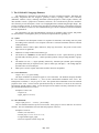
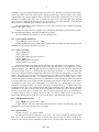
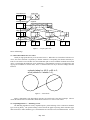
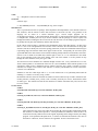
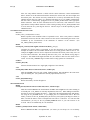
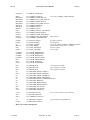
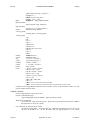
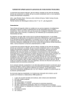
Figure 1 shows the data structure for an uncolored square that is generated by the following UNIGRAFIX statements:
v
v
v
v
f
v1 0 0
v2 1 0
v3 1 1
v4 0 1
square
0;
0;
0;
0;
(v1 v2 v3 v4);
For the square polygonal face, we have a list of all of the face’s contours, each contour has a list of edge
directions and edges, and each edge has a list of vertices (always two). Also each of the above types has a
list of all references to it — vertices have a list of edges to which they belong, edges have a list of contours,
and contours have an associated face. Since edges are shared between faces, it works well to have them be
another statement type (and it will help when adding UNICUBIX extensions). Since contours are not shared,
the only advantage of having them be a separate statement is to share implementation code. (Contours
might conceivably be shared among the curved patches from UNICUBIX, but it probably only would be useful for border contours.)
Missing from figure 1 are the links between statements of the same type. All statements of the same
type in a definition or scene are connected in a doubly linked list. Being able to visit all statements in a
particular order is important when writing the data structure to a text file because identifiers need to be
defined before they are referenced. It is also important for flattening instance hierarchies (see section
May 1994
- 10 -
face statement
contour list
square
contour statement
edge list
fwd
fwd
v2
1,0,0
fwd
fwd
edge statements
vertex statements
v1
0,0,0
v3
1,1,0
v4
0,1,0
Figure 1 — simple square face
below on flattening).
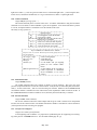
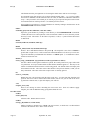
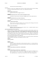
3.3. Hierarchical References to Vertices
Usually an edge points directly to its associated vertices. When there is a hierarchical reference to a
vertex, the vertex statement is replaced by a shadow statement. Conceptually, the shadow statement pretends it is the actual vertex and then uses the instantiation path to return modified coordinate and normal
values. Transforming the shadowed vertex information is computationally expensive in comparison to just
copying the coordinate or normal values, but it is sometimes the best way to describe linkages between
instances.
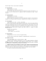
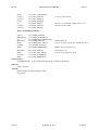
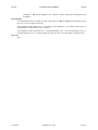
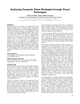
a wheels (wheel -rz -45) 2 -rz 90 -tx 3;
w link (wheels:0.v1 wheels:1.v1);
Figure 2 — train wheels
Figure 2 demonstrates why hierarchical references are useful with a train wheel example. The two
wheels are linked with a wire that makes hierarchical references to a vertex in each wheel.
3.4. Expanding Instances — Flattening a Scene
The flattening algorithm is heavily dependent upon a partial ordering of the UNIGRAFIX statement
types in the ug library. The partial ordering is derived from the graph expressing which statement types
make references to other statement types. Statements that are referred to need to be flattened first. If a new
May 1994
- 11 -
statement type is introduced, it needs to placed in the correct order relative the other statement types. The
current ordering is as follows: textures, materials, lights, definitions, instances, arrays, shadows, vertices,
edges, contours, wires, faces, cameras, and extensions. When the UNICUBIX statement types are incorporated, the edge and border types will be either immediately before or after edges, and patches will be
either immediately before or after faces.
Shadow statements are used as place holders for hierarchical references to vertices. As each instance
is expanded, the hierarchical name of the instance is cached. A vertex has a flag stating whether or not it is
shadowed. When a shadowed vertex is transformed, all of the shadow statements that refer to it are examined to see if the name used to refer to the vertex matches the current hierarchical name (i.e. if the shadow
statement’s name is a suffix of the current hierarchical name). This handles multiple hierarchical references through multiple levels of instantiation. There is a computational cost of maintaining the current
hierarchical name which is wasteful in scenes that don’t have any hierarchical references. Luckily, the
overhead is fairly low and is proportional to the instance tree complexity of scene, which should be at least
an order of magnitue smaller than the number of primitives duplicated (vertices, edges, wires, faces, etc.).
3.5. Nested Definitions
Each definition has its own lexical scope and is assigned a unique lexical level number, an LLN. A
LLN is never reused during a program. An explicit list of visible LLN’s is maintained while parsing the
UNIGRAFIX language to track in which scopes an identifier might be found. Local identifiers override
identifiers with the same name in outer scopes. How LLN’s work to improve symbol table performance is
described in [Cook83]. The application programmer rarely uses the fact that there is a full symbol table
available, as most applications implicitly work with scene descriptions that have no definitions in them (i.e.
flat scenes). One exception is the bump animation package [Oakland87] which uses scoped language
extensions to implement its features.
There is one implementation detail in the hash table used for the symbol table code that needs
explaining. By design, the hash table uses the linked-list chaining method to reduce lookup time for symbols while parsing. The UG_symbol structure is the linked-list element that is used to maintain the chain,
and the UGstmt structure points back to the UG_symbol in the hash chain that references the UGstmt. The
back pointer is used to remove the entry from the symbol table when a named statement is deleted.
Because the hash chain is a singly linked list, the UG_symbol is never reclaimed, thus causing a small
memory leak each time a named statement is deleted. Should this be a problem, it will be possible to
reclaim the space the next time that hash chain is searched.
May 1994
- 12 -
References
[Bui-Toung75] Phong Bui-Toung, ‘‘Illumination for Computer-Generated Pictures,’’ Communications of
the ACM, 18(6):311-317, June 1975.
[Cook83] Robert P. Cook, Thomas J. LeBlanc, ‘‘A Symbol Table Abstraction to Implement Languages
with Explicit Scope Control,’’ IEEE Transactions on Software Engineering, 9(1):8-12, January 1983.
[Foley90] James D. Foley, Andries van Dam, Steven K. Feiner, John F. Hughes, Computer Graphics: Principles and Practice, Addison Wesley, Reading, MA, 1990.
[Funkhouser92] Thomas Funkhouser, Carlo H. Séquin, Seth Teller, ‘‘Management of Large Amounts of
Data in Interactive Building Walkthroughs,’’ Proceedings of the 1992 ACM SIGGRAPH Symposium
on Interactive 3D Graphics, Boston, MA, 1992.
[Hanrahan82] P. Hanrahan, ‘‘Creating Volume Models from Edge-Vertex Graphs,’’ Computer Graphics,
16(3):77-84, July 1982.
[Neider93] Jackie Neider, Tom Davis, Mason Woo, OpenGL Progamming Guide, Addison Wesley, Reading, MA, 1993.
[Oakland87] Steven Anders Oakland, ‘‘BUMP, a Motion Description and Animation Package,’’ Master’s
Report, U. C. Berkeley, September 1987.
[Séquin84] Carlo H. Séquin, ‘‘The UNIGRAFIX 2 System,’’ Proceedings National Computer Graphics
Association Conference, Anaheim, CA, May 1984.
[Séquin90] Carlo H. Séquin, Kevin P. Smith, ‘‘Introduction to the Berkeley UNIGRAFIX Tools Version
3.0,’’ Technical Report UCB/CSD 90/606, Berkeley, California, November 1990.
[Shirman90] Leon A. Shirman, ‘‘Construction of Smooth Curves and Surfaces from Polyhedral Models,’’
Technical Report UCB/CSD 90/602, Berkeley, California, December 1990.
May 1994
UG ( 3 )
UNIGRAFIX’s Users Manual
UG ( 3 )
NAME
ug — manipulate UNIGRAFIX data structures
SYNOPSIS
#include <ug.h>
cc -I${UGHOME}/include ... -L${UGHOME}/lib -lug -lmat -lcompat
DESCRIPTION
This is a specification for the UG package, which implements all manipulations of the internal UNIGRAFIX
data structures, and the transfer of those data structures to and from text files. The grammar of the
language can be found in a related document ug(5). Several sample programs are in
src/packages/ug/examples. A file with fragments showing how to wind around in the topology statements
is examples/refer. Probably the best way to become familiar with this packages is to have a quick read
through this manual, including the macro section at the end, then look over the sample programs and possibly modify them to gain some familiarity with the data structures.
In the context of this package, a statement is the fundamental object in the data structure. In many cases
there is a one to one correspondence between lines in the UNIGRAFIX file and statements in the ug data
structures, but this is notably not true for the topology statements, as there are intermediate statement types
representing edges and contours which do not appear in the text files. Conceptually, the user of this package should think of the data structure as an ordered, branching, doubly-linked list of statements, and a statement as a sort of variant record which may contain a light, a vertex, etc. To see what data is in the variant
part of each statement, look at the macro listings at the end of the manual. It is also possible to loop
through all of the statements of any one type in a file.
All references between statements are mediated through reference lists. Every statement has a TO list,
which contains pointers to all statements which refer to it, and a FROM list which contains pointers to all
statements to which it refers. FROM lists always contain at least one entry, which is a pointer to a NULL
statement, for example, a face with no color will have it’s FACE_COLOR index set to refer to the NULL
reference in it’s FROM list.
Statments in text files which begin with a "(" are read verbatim into a UG_ESCAPE_STMT until the
matching ")" is found. See UGset_escape_routine.
Hierarchical references from one statement to another are allowed and are kept in shadow statements (See
UGfind_reference, UGfind_vertex_coords). This is currently used only for vertices, but should be usable
for other types. The routines here hide the fact that there are shadow statements fairly well, but one must
be aware of them.
I/O ROUTINES
UGfile ∗
UGread(UGfile ∗uf, FILE ∗fp, const char ∗filename, int first_line)
UGfile ∗
UGread_str(UGfile ∗uf, char ∗str, const char ∗filename, int first_line)
UGfile ∗
UGread_lls(UGfile ∗uf, FILE ∗fp, int ∗lln_list, int lln_cnt, const char ∗filename, int first_line)
UGfile ∗
UGread_str_lls(UGfile ∗uf, char ∗tr, int ∗lln_list, int lln_cnt, const char ∗filename, int first_line)
These functions read a scene from either the file pointer fp or the string str, and build the internal
data structure (a UGfile) that represents it. This representation is sufficient to allow the file to be
written back in nearly identical form to the original, depending on the changes made by the calling
program. If the parameter uf equals NULL, a structure is allocated and returned as the value of
the function. Otherwise, the new UGstmt’s are appended. NULL is returned on errors.
3.1 Release
September 20, 1994
Page 13
UG ( 3 )
UNIGRAFIX’s Users Manual
UG ( 3 )
The filename and first_line arguments are for setting the initial values used for error messages.
If a statement being read needs to refer to objects defined outside of uf — e.g. if you are reading
the inside of a definition, and the statement refers to colors (or definitions) outside the definition’s
scope — then you need to use UGread_lls (or UGread_str_lls) to provide the parser with a lexical
level number stack for UGfind_reference. See UGfind_reference, below.
Files included via UNIGRAFIX’s include mechanism are found by looking in the directories in the
UGMODELPATH environment variable.
FILE ∗
UGmodel_open(const char ∗filename, const char ∗mode)
Opens the given filename by looking in each directory in the UGMODELPATH environment
variable (directories are colon separated). If the environment variable is not set, then only current
directory is used. The mode’s are the same as fopen(3S). Csh(1)’s ˜ syntax for home directories
is understood.
BOOL
UGwrite(UGfile ∗uf, int indent, FILE ∗fp)
BOOL
UGwrite_stmt(UGstmt ∗us, int indent, FILE ∗fp)
Writes a file or individual statement to file pointer fp. The output file is not closed. If indent is
greater than or equal to zero, it will be used as the initial indentation level, and every level of nesting will be indented by an additional four characters. If indent equals -1, no indentation is done.
FALSE is returned on error.
BOOL (∗∗
UGset_escape_routine(BOOL (∗∗rp)(UGstmt ∗, UGfile ∗)))(UGstmt ∗, UGfile ∗)
Got that? When an unrecognized statement is parsed, the routine pointed to by rp is called with
two parameters: an escape UGstmt and the UGfile that the statement appears in. This may be the
UGfile of a definition nested inside the text file being parsed. The default routine will simply add
the statement to the file. The return value of this function is the previous function, so that you can
daisy chain them. The return value of the escape routine is currently ignored.
int
UGerror_code(void)
Returns the error code associated with the most recent error. At some point this document will
spell out what errors can be returned from what routines, but for now you can look at the list in
ug.h and use common sense, or just call UGprint_error and exit.
void
UGprint_error(void)
Prints a text message on stderr describing the most recent error. Some UG routines supply
UGprint_error with an additional string giving details about the error.
FILE ROUTINES
UGfile ∗
UGnew_file(void)
Allocates a file. Returns NULL on error.
UGfile ∗
UGcopy_file(UGfile ∗to, UGfile ∗from)
Makes a brand new, identical copy of from. To may be NULL, in which case it is allocated and
returned as the function value. NULL return on errors.
Page 14
September 20, 1994
3.1 Release
UG ( 3 )
UNIGRAFIX’s Users Manual
UG ( 3 )
BOOL
UGdelete_file(UGfile ∗uf, BOOL safe)
Recursively delete all statements in uf, then uf. The caller may set safe to TRUE if memory can
be freed without doing all of the maintenance to the topology, because it is known that this file is
not referred to in other parts of the data structure. Safe currently only affects whether memory is
freed or not.
UGfile ∗
UGflatten(UGfile ∗uf, const char ∗prefix, BOOL shorten)
The specified file uf is flattened, and the resulting flat file is returned. Prefix is prepended to all
generated names and may be blank. If there is no need for the flattened names to be descriptive,
pass TRUE for shorten, but do use a prefix that will avoid collisions. If short names are not used,
the output names will be of the form prefix_iname_aname#index_..._name, where iname is an
instance name, aname is an array name, and name is the original name of the statement. Flattening is considerably faster with short names. Also note that objects that are referred to by hierarchical referencing will retain their full names, even if shorten is TRUE.
STATEMENT ROUTINES
UGstmt ∗
UGalloc_stmt(int type)
Allocates the data structure for a statement of type type (defined below). Returns NULL if there
are problems.
BOOL
UGadd_stmt(UGstmt ∗stmt, int loc, UGstmt ∗ptr, UGfile ∗uf, BOOL nameok)
Adds stmt to uf. If loc is UG_BEG or UG_END, stmt is put at the beginning or the end of the
file, respectively. If loc is UG_ARB, stmt is placed before the statement pointed to by ptr, or if
ptr is NULL, at the end of the file. The parameter nameok may be set to TRUE if it is known
that the name of the new statement does not conflict with any other statement in this file, in order
to reduce the processing time. FALSE is returned on error.
UGstmt ∗
UGcopy_stmt_data(UGstmt ∗to, UGstmt ∗from)
Copies all of the data associated with from to to. The statement name and the reference lists are
not copied, but elements of the data which point into the reference list are. To may be NULL, in
which case it is allocated and returned. Chances are you should be using UGcopy_file instead of
just the statement data.
BOOL
UGdelete_stmt(UGstmt ∗stmt, BOOL safe)
Removes the statement from the data structure, and hopefully does the right thing if this affects
the topology of an object. If safe is TRUE, then the statement can be freed as well and no maintenance is done to topology because it is known that this statement is not referred to, or because all
associated statements will be deleted subsequently. Returns FALSE on error. (Even when safe is
FALSE, no maintenance is done to topology.)
BOOL
UGfree_stmt(UGstmt ∗stmt)
Frees the memory associated with a statement. This should be used to get rid of statments that
have never been added to files, but just used independently. In the case of definition statements,
the statements inside the UG_DEF_BLOCK are not deleted or freed. Use UGdelete_file for that
purpose.
3.1 Release
September 20, 1994
Page 15
UG ( 3 )
UNIGRAFIX’s Users Manual
UG ( 3 )
UGidx
UGalloc_ref(UGstmt ∗from, UGstmt ∗to)
Creates a reference handle between the statements. To is placed on from’s reference FROM list,
and vice versa. The UGidx returned is the index in from’s FROM list. Thus to make a face red,
assuming you have a color statement pointed to by red and a face statement pointed to by face,
you would do UG_FACE_COLOR(face) = UGalloc_ref(face, red). To find a face’s color statement you would look at UG_REF_FROM(face, UG_FACE_COLOR(face)). To find all of the
edges that use a given vertex:
UGstmt ∗vertex, ∗edge;
UGidx i;
for (i = 0; i < UG_STMT_TO_COUNT(vertex); i++) {
edge = UG_REF_TO(vertex, i);
if (UG_STMT_TYPE(edge) != UG_EDGE_STMT)
continue;
...
}
UGstmt ∗
UGfind_reference(const char ∗name, int type, int ∗lln_list, int lln_cnt, UGfile ∗where)
Returns a pointer to the UGstmt that defines the specified name of the given type. Returns NULL
either on error or if the name is not found. Lln_list is an array of lexical level numbers in which
to look for the statement, and lln_cnt is the number of entries in lln_list. For most statement
types, only the last scope (lln_list[lln_count - 1]) on the list is searched. For open scope statements (defs, colors, and lights), if there are statements by the same name in several of the scopes
in lln_list, the last one is used (i.e. the innermost scope). Note that the lln for a UGfile can be
obtained using the UG_FILE_LLN macro. Also note that if you are looking in only one scope,
say scope x, it is simplest to pass lln_list = &x, lln_cnt = 1 (You might want to use
UGfind_by_name instead — see below).
A name may also be prefixed by a series of ’.’ separated instance and array names. (Arrays must
be subscripted with an : followed by an element number). In this case, the scope should be the
scope in which the first instance (or array) name is defined. If this is done, a
UG_SHADOW_STMT statement will be added to the file where. The where parameter should
therefore point to the UGfile where a reference to the named object will exist. (This parameter
may be NULL if you know that there are no periods in the name.) This allows flattening to take
place properly. The return value from this function will be the pointer to the shadow statement.
Shadow statements are skipped by the loop macros available to the applications programmer.
UGstmt ∗
UGfind_by_name(const char ∗name, int type, UGfile ∗uf, MATmatrix mat)
Returns a pointer to the UGstmt that defines the specified name of the give type. Returns NULL
either on error or if the name is not found. Only looks in the given UGfile, uf, and if it is a
hierarchical reference, there are no side-effects, i.e. it will never return a shadow statement (see
UGfind_reference). The resulting pointer is not usable for adding as a reference in the data structure, but is useful for checking for existence and for extracting values. If a non-null value is
passed in for the matrix argument, it is filled in with the transformation matrix of the found statement from the given UGfile (i.e., from hierarchical references).
int
UGwalk_inst_hier(UGfile ∗ugfile, MATmatrix matrix, const UGwalk_funcs ∗funcs)
Recursively descends the instance hierarchy starting with the given transformation matrix. The
funcs argument contains callback function pointers for all statement that you are interested in.
For each instance the optional push_matrix callback function is called. Then in the statement type
Page 16
September 20, 1994
3.1 Release
UG ( 3 )
UNIGRAFIX’s Users Manual
UG ( 3 )
order, the setup callback function is called with the current statement, current transformation
matrix, whether or not the statement should be mirrored, the current color, the current lights, and
the instance path. The instance and array statements are recursively descended after the setup
callback function has been called. If a shadowed statement sets its UG_STMT_EXTRA field,
then that value is automatically propagated to the UG_STMT_EXTRA field of the appropriate
shadow statement. After all of the statements have been visited once, each statement is visited
again and the cleanup callback function is called. During cleanup, the UG_STMT_EXTRA field
is free’d unless the save_extra flag has been set. The last step is to call the optional pop_matrix
callback function.
STATEMENT SPECIFIC ROUTINES
MATreal ∗
UGfind_vertex_coords(UGstmt ∗vertex)
Returns a pointer to the coordinate values of a particular vertex. If the vertex pointer is a shadow
(hierarchical reference) then the values returned are the result of transforming the actual vertex
coordinates by the concatenation of the transforms of instances in the reference. (See
UG_VERT_POINT_SAFE macro.)
BOOL
UGcompute_camera(UGfile ∗ugfile, UGstmt ∗cam, float y_over_x)
Computes the camera matrices represented by the data described in the camera statement.
Attempts are made to fill in reasonable default values for viewing options which are not set. For
example, the ugfile’s extent is used to compute the look from and look at points if they were not
set in the camera statement. The default up direction is the y axis. The default viewing angle is
30 degrees. The default focal length (and film size) are chosen to make sure the whole scene is
visible. Use the UG_CAMERA flags to control which viewing options are considered set.
UGllist ∗
UGalloc_llist(void)
Allocates the data structure for a single light (a light list of one element).
void
UGadd_llist(UGllist ∗llist, UGstmt ∗stmt, int loc, UGllist ∗ptr)
Adds the light llist to the given UG_LIGHT_STMT statement. Loc and ptr have the same meaning as in UGadd_stmt. (UG_ARB is not currently implemented, however.)
void
UGfree_llist(UGllist ∗beg)
Release the memory used for the light list.
TRANSFORMATIONS
BOOL
UGadd_tform(UGtform ∗tform, UGtlist ∗tlist, int loc, UGtform ∗ptr)
Adds the transform tform to the transformation list tlist. Loc and ptr have the same meaning as
in UGadd_stmt. (UG_ARB is not currently implemented, however.) When adding a transformation there is no need to compute the matrix — simply fill in the transformation name and parameters using the UG_TFORM macros. If you change part of a transformation after it has been
added, you must set the UG_TFORM_MAT_OK and UG_TLIST_MAT_OK flags to FALSE, to
make sure that the matrix will be recomputed the next time it is asked for. For -M3 and -M4
transformations, you may set the UG_TFORM_MIRROR macro if you want contours to be
reversed. This is set automatically for -m? transforms.
BOOL
UGdelete_tform(UGtform ∗tform, UGtlist ∗tlist)
Removes tform from tlist. Not implemented. (Of course you can always set it to an identity
3.1 Release
September 20, 1994
Page 17
UG ( 3 )
UNIGRAFIX’s Users Manual
UG ( 3 )
transform and clear the matrix OK flags ...).
EXTENTS
Typically you will use the _EXTENT macros instead of using the following routines, because bounding
box extents are maintained automatically for instance, array, and definitions statements.
UGextent ∗
UGnew_extent(UGextent ∗∗pext)
Allocates an extent, saves it in ∗pext, and return it.
UGextent ∗
UGtform_extent(UGextent ∗out, const UGextent ∗in, MATmatrix matrix)
Transforms the extent by the given non-projective matrix, place the result in out, and return it.
UGextent ∗
UGmerge_extent(UGextent ∗in_out, const UGextent ∗in)
Combines two extents, place the result back into the first one, and return it.
UGextent ∗
UGclear_extent(UGextent ∗∗pext)
Clears an extent by setting the minimum values to the largest positive floating point value and
maximun values to the negative of the minimum values.
void
UGclear_stmt_extent(UGstmt ∗)
Recursively, clears the extent for the given instance, array, or definition statement and all
definitions/instances/arrays that refer to it.
ROUTINES FOR MANIPULATING TOPOLOGY
Edge lists (UGelist’s) are doubly, circularly linked lists, each element of which contains a reference (see
UGalloc_ref) to an edge, and a direction. A contour statement has a UGelist as it’s only data item. The
references in the UGelist are indices into a contour’s FROM list. Keep in mind that for a face contour, the
edge that connects the last vertex to the first must still be explicit — wire contours are circularly linked
also. Similarly, faces and wires have UGclist’s which are lists of references to contours. It is always up to
you to be sure that edge lists are consistent, i.e. that the last vertex of one edge matches the first vertex of
the next edge (keeping in mind the ELIST_DIRection).
The clist manipulation routines are a subset of the elist routines if you ignore all references to direction and
replace all UGelist’s with UGclist’s (new and old are now faces or wires).
UGelist ∗
UGalloc_elist(void)
UGclist ∗
UGalloc_clist(void)
Allocates a UGelist, circularly links it to itself, and returns a pointer to it. You must use this routine for all allocation of elists, because all of the following routines assume (and maintain) circular
linked-ness for all UGelists.
UGelist ∗
UGsplice_elist(UGelist ∗pos, UGelist ∗new, UGelist ∗∗head)
UGclist ∗
UGsplice_clist(UGclist ∗pos, UGclist ∗new, UGclist ∗∗head)
Inserts the list new after pos. Pos is normally an element of the elist pointed to by head. If pos is
NULL then head is set to point to new. Head will typically be the address of a
UG_CONTOUR_ELIST. The return value is always ∗head. If new is NULL nothing is done.
Page 18
September 20, 1994
3.1 Release
UG ( 3 )
UNIGRAFIX’s Users Manual
UG ( 3 )
UGelist ∗
UGunsplice_elist(UGelist ∗beg, UGelist ∗end, UGelist ∗∗head)
UGclist ∗
UGunsplice_clist(UGclist ∗beg, UGclist ∗end, UGclist ∗∗head)
Separates the list pointed to by ∗head into two parts. One piece will run from beg to end, and the
remaining piece will still be pointed to ∗head. The return value of the function is a pointer to the
list begun by beg. If ∗head is somewhere between beg and end inclusively, it is set to point to any
element remaining in the initial list, or NULL if the whole list is unspliced from itself. Beg and
end may be equal.
UGelist ∗
UGkill_elist(UGelist ∗beg, UGelist ∗end, UGelist ∗∗head)
UGclist ∗
UGkill_clist(UGclist ∗beg, UGclist ∗end, UGclist ∗∗head)
Same as UGunsplice_elist, but elements that are unspliced are then freed. Return value is ∗head.
UGelist ∗
UGmirror_elist(UGelist ∗el)
Reverses the order of all edges in el in place and returns a pointer to the elist entry that starts with
the same vertex as el did. Essentially all of the ELIST_NEXT and ELIST_PREV pointers are
swapped, and the ELIST_DIR’s are toggled. (Try it on paper).
UGelist ∗
UGduplicate_elist(UGelist ∗el)
UGclist ∗
UGduplicate_clist(UGclist ∗el)
Makes a new copy of el and returns a pointer to it.
UGelist ∗
UGconvert_elist(UGelist ∗el, UGstmt ∗new, UGstmt ∗old)
UGclist ∗
UGconvert_clist(UGclist ∗el, UGstmt ∗new, UGstmt ∗old)
You didn’t start to think of elist’s as pointing to edges did you? Remember, they contain UGidx’s
that are relative to a contour’s FROM reference list. This routine changes each element of el so
that it points to the same edges in new as it used to in old, adding new elements to new’s reference FROM list, and taking them out of old’s. It also removes the references to old in the el’s
edges’s TO list. So a typical operation might be to unsplice some edges from one contour, convert
the elist, and splice it into another contour.
UGelist ∗
UGreplace_edge_in_all(UGstmt ∗edge, int dir, UGelist ∗elist, UGstmt ∗ref_contour)
For every contour which uses edge, we replace edge with elist. Elist is defined relative to
ref_contour. Dir is the relative direction of elist to the verts in edge, so if edge contains the verts
A and B, and elist is AX-YB, dir should equal zero.
ROUTINES FOR CREATING EDGES AND CONTOURS EASILY
UGstmt ∗
UGmake_edge(UGstmt ∗v1, UGstmt ∗v2, int ∗dir, UGfile ∗uf, UGstmt ∗ptr)
If an edge already exists connecting v1 and v2, it is returned, and ∗dir is set appropriately (0 if the
existing edge lists v1 first, 1 if it lists v2 first). If not, a new edge UGstmt is created before ptr in
3.1 Release
September 20, 1994
Page 19
UG ( 3 )
UNIGRAFIX’s Users Manual
UG ( 3 )
uf, ∗dir is set to 0, and the new statement pointer is returned.
UGelist ∗
UGmake_edge_for_contour(UGstmt ∗v1, UGstmt ∗v2, UGfile ∗uf, UGstmt ∗contour, UGstmt ∗ptr)
Does a UGmake_edge, and creates an elist for contour that points to the edge. This new elist has
its dir all set, and contour’s FROM list is updated to point to the new edge. In other words, the
elist that is returned is all ready to be spliced into contour.
UGstmt ∗
UGmake_contour(UGstmt ∗∗vlist, BOOL face, UGfile ∗uf, UGstmt ∗ptr)
Vlist is an array of pointers to vertex (and/or shadow) UGstmts, terminated by a NULL. Creates
and returns a contour UGstmt whose elist contains an edge between each adjacent pair of vertices.
If face is TRUE, an additional edge is created from the last vertex to the first vertex. The contour
is added to uf before ptr.
BOOL
UGmake_contours(UGstmt ∗stmt, UGfile ∗uf, UGstmt ∗∗vlist, UGstmt ∗ptr)
This is not exactly symmetrical with the previous routine, so read carefully. Vlist is now a list of
verts of the following form: NULL v1 v2 v3 ... NULL v4 v5 ... NULL ... NULL NULL. Each null
separated piece is passed to make_contour, and the result is spliced on to the end of stmt’s clist.
Stmt should be either a face or a wire statement. This is quite special purpose, but sometimes it is
convenient. All of the new contours will be put before ptr in uf. New clist entries are created for
each new contour, and they are spliced on to stmt’s clist at the end.
COLOR
void
UGhls_to_shade(float h, float l, float s, UGshade ∗color)
Convert a HLS color triple to RGB color.
void
UGshade_to_hls(UGshade ∗color, float ∗h, float ∗l, float ∗s)
Convert a RGB color to a HLS triple.
DEFINITIONS AND MACROS
Currently defined statement types:
UG_ARRAY_STMT
UG_CAMERA_STMT
UG_COLOR_STMT
UG_COMMENT_STMT
UG_CONTOUR_STMT
UG_DEF_STMT
UG_EDGE_STMT
UG_ESCAPE_STMT
UG_FACE_STMT
UG_INSTANCE_STMT
UG_LIGHT_STMT
UG_SHADOW_STMT
UG_TEXTURE_STMT
UG_VERT_STMT
UG_WIRE_STMT
Currently defined statement flags:
UG_STMT_SHADOWED
UG_VERT_HAS_NORMAL
Page 20
September 20, 1994
3.1 Release
UG ( 3 )
UNIGRAFIX’s Users Manual
UG ( 3 )
UG_FACE_HAS_PLANE_EQ
UG_DEF_IS_SOLID
UG_CAMERA_HAS_FROM
UG_CAMERA_HAS_AT
UG_CAMERA_HAS_UP
UG_CAMERA_HAS_FLEN
UG_CAMERA_HAS_CLIP
UG_CAMERA_HAS_FILM
UG_CAMERA_HAS_ANGLES
UG_CAMERA_HAS_PORTHOLE
UG_COLOR_HAS_EMISSION
UG_COLOR_HAS_AMBIENT
UG_COLOR_HAS_DIFFUSE
UG_COLOR_HAS_SPECULAR
UG_COLOR_HAS_TRANS
UG_COLOR_HAS_SHININESS
UG_INST_HAS_EXTENT
UG_ARRAY_HAS_EXTENT
Macro parameter types:
uf = UGfile ∗
us = UGstmt ∗
utf = UGtform ∗
utl = UGtlist ∗
cl = UGclist ∗
el = UGelist ∗
ll = UGllist ∗
sh = UGshade ∗
idx = UGidx = int
type = int
A UGref is equivalent to a UGstmt ∗∗.
Macros for files and statements:
UGstmt ∗
UGstmt ∗
int
UGextent ∗
UG_FIRST_TYPE(uf, type)
UG_LAST_TYPE(uf, type)
UG_FILE_LLN(uf)
UG_FILE_EXTENT(uf)
first statement of this type
last statement of this type
Lexical Level Number (scope #) of UGfile
extent of UGfile
UGstmt ∗
UGstmt ∗
UGstmt ∗
char ∗
int
UGfile ∗
int
void ∗
void ∗
UGref []
UGref []
int
int
UG_NEXT_TYPE(us)
UG_NEXT_TYPE_SAFE(us)
UG_PREV_TYPE(us)
UG_STMT_NAME(us)
UG_STMT_TYPE(us)
UG_STMT_FILE(us)
UG_STMT_LLN(us)
UG_STMT_APPL(us)
UG_STMT_EXTRA(us)
UG_STMT_TO(us)
UG_STMT_FROM(us)
UG_STMT_TO_COUNT(us)
UG_STMT_FROM_COUNT(us)
next statement of same type
same with guard against NULL us
previous statement of same type
statement’s optional name
statement’s type
UGfile statement belongs to
LLN of UGfile statement belongs to
application data — not touched by library
used for instance traversal — available otherwise
references TO this statement
references FROM this statement
number of references TO this statement
number of references FROM this statement
3.1 Release
September 20, 1994
Page 21
UG ( 3 )
UNIGRAFIX’s Users Manual
UG ( 3 )
Reference macros:
UGref
UGref
UG_REF_TO(us, idx)
UG_REF_FROM(us, idx)
Flag macros:
BOOL
void
void
UG_STMT_FLAG_SET(us, flag)
UG_STMT_SET_FLAG(us, flag)
UG_STMT_CLEAR_FLAG(us, flag)
test if statement flag is set
set statement flag
clear statement flag
Loop macros:
UG_FOR_ALL_STMTS(us, uf, type)
visit all statements in uf
UG_FOR_ALL_STMTS_SAFE(us, uf, type, tmp_us)
UG_FOR_ALL_STMTS_REALLY(us, uf, type, tmp_us) even shadow statements
UG_FOR_ALL_TYPE(us, uf, type)
UG_FOR_ALL_TYPE_SAFE(us, uf, type, tmp_us)
UG_FOR_ALL_TFORMS(utf, utl)
UG_FOR_ALL_TFORMS_SAFE(utf, utl, tmp_utf)
Use the SAFE versions of the macros whenever you might be deleting the object pointed to by the loop
variable. The tmp_ variables are used by the loop, but contain no information for the user.
Macros specific to given statement types:
Page 22
MATpoint
MATpoint
MATvec
MATvec
UGidx
UGidx
UG_VERT_POINT(us)
UG_VERT_POINT_SAFE(us)
UG_VERT_NORMAL(us)
UG_VERT_NORMAL_SAFE(us)
UG_VERT_COLOR(us)
UG_VERT_COLOR_SAFE(us)
UGidx [2]
UG_EDGE_VERTS(us)
UGelist ∗
UG_CONTOUR_ELIST(us)
UGclist ∗
MATvec
UGidx
UGidx
float
UG_FACE_CLIST(us)
UG_FACE_PLANE_EQ(us)
UG_FACE_COLOR(us)
UG_FACE_LIGHTS(us)
UG_FACE_LIGHTNESS(us)
UGclist ∗
UGidx
float
UG_WIRE_CLIST(us)
UG_WIRE_COLOR(us)
UG_WIRE_LIGHTNESS(us)
UGfile ∗
UG_DEF_BLOCK(us)
UGidx
UGidx
UGidx
UGtlist ∗
UGextent ∗
UG_INSTANCE_DEF(us)
UG_INSTANCE_COLOR(us)
UG_INSTANCE_LIGHTS(us)
UG_INSTANCE_TLIST(us)
UG_INSTANCE_EXTENT(us)
UGidx
UGidx
UGidx
int
UGtform ∗
UGtform ∗
UG_ARRAY_DEF(us)
UG_ARRAY_COLOR(us)
UG_ARRAY_LIGHTS(us)
UG_ARRAY_SIZE(us)
UG_ARRAY_INIT_TLIST(us)
UG_ARRAY_INC_TLIST(us)
follows shadow statements
follows shadow statements
follows shadow statements
September 20, 1994
3.1 Release
UG ( 3 )
UNIGRAFIX’s Users Manual
UGextent ∗
UG_ARRAY_EXTENT(us)
BOOL
MATmatrix
MATmatrix
MATmatrix
MATmatrix
MATpoint
MATpoint
MATvec
float
float [2]
float [2]
float [2]
UGextent
UG_CAMERA_TYPE(us)
one of UG_CAMERA_{PERS, ORTHO}
UG_CAMERA_VIEW_MAT(us)
UG_CAMERA_INV_VIEW_MAT(us)
UG_CAMERA_PERS_MAT(us)
UG_CAMERA_INV_PERS_MAT(us)
UG_CAMERA_FROM(us)
UG_CAMERA_AT(us)
UG_CAMERA_UP(us)
UG_CAMERA_FOCAL_LENGTH(us)
UG_CAMERA_FILM_SIZE(us)
UG_CAMERA_VIEW_ANGLES(us)
UG_CAMERA_CLIP_PLANES(us) hither and yon
∗UG_CAMERA_PORTHOLE(us)
UGllist ∗
UGllist ∗
int
MATvec
float
UGidx
UG_LIGHT_LLIST(us)
UG_LIGHT_END(us)
UG_LLIST_TYPE(ll)
UG_LLIST_DIR(ll)
UG_LLIST_INTENS(ll)
UG_LLIST_COLOR(ll)
UGshade ∗
UGshade ∗
UGshade ∗
UGshade ∗
float
float
UGidx
UG_COLOR_EMISSION(us)
UG_COLOR_AMBIENT(us)
UG_COLOR_DIFFUSE(us)
UG_COLOR_SPECULAR(us)
UG_COLOR_SHININESS(us)
UG_COLOR_TRANS(us)
UG_COLOR_TEXTURE(us)
float
float
float
UG_SHADE_R(sh)
UG_SHADE_G(sh)
UG_SHADE_B(sh)
int
char ∗
int
int
int
int
int
int
float
float
void ∗
UG_TEXTURE_IMAGE_TYPE(us)
UG_TEXTURE_IMAGE_NAME(us)
UG_TEXTURE_IMAGE_WIDTH(us)
UG_TEXTURE_IMAGE_HEIGHT(us)
UG_TEXTURE_IMAGE_NCOMPONENTS(us)
UG_TEXTURE_WRAP(us)
UG_TEXTURE_MINFILTER(us)
UG_TEXTURE_MAGFILTER(us)
UG_TEXTURE_USCALE(us)
UG_TEXTURE_VSCALE(us)
UG_TEXTURE_IMAGE(us)
void ∗
char ∗
UG_ESCAPE_TAG(us)
UG_ESCAPE_TEXT(us)
char ∗
UG_COMMENT_TEXT(us)
int
UGidx
UG_SHADOW_TYPE(us)
UG_SHADOW_LINK(us)
UG ( 3 )
first light in light list
end of light list
one of UG_LIGHT_{DIRECT, AMBIENT, POINT}
actually holds a point if type is _POINT
intensity of light
color of light
red component of shade
green component of shade
blue component of shade
can be used to classify escape statments
type of statement being shadowed
Macros for contour and edge lists:
3.1 Release
September 20, 1994
Page 23
UG ( 3 )
UNIGRAFIX’s Users Manual
UG ( 3 )
UGidx
UGclist ∗
UGclist ∗
UG_CLIST_CONTOUR(cl)
UG_CLIST_NEXT(cl)
UG_CLIST_PREV(cl)
circularly, doubly linked
UGidx
int
UGelist ∗
UGelist ∗
UG_ELIST_EDGE(el)
UG_ELIST_DIR(el)
UG_ELIST_NEXT(el)
UG_ELIST_PREV(el)
index (0 or 1) into EDGE_VERTS of first vertex
Circularly, doubly linked
Macros for handling transforms:
char [3]
MATreal [16]
int
MATmatrix
BOOL
UGtform
BOOL
UG_TFORM_TYPE(utf)
UG_TFORM_PARAMS(utf)
UG_TFORM_NUM_PARAMS(utf)
UG_TFORM_MAT(utf)
UG_TFORM_MAT_OK(utf)
∗UG_TFORM_NEXT(utf)
UG_TFORM_MIRROR(utf)
MATmatrix
BOOL
UGtform ∗
BOOL
UG_TLIST_MAT(utl)
UG_TLIST_MAT_OK(utl)
UG_TLIST_TFORMS(utl)
UG_TLIST_MIRROR(utl)
maintained for you
clear if you change a tform after UGadd_tform’ing it
TRUE if contours should reverse
maintained for you
clear this if you change any tform
ENVIRONMENT
UGMODELPATH — a colon separated list directories to search for include files
SEE ALSO
mat(3), compat(3)
AUTHOR
Michael Natkin, February through April 1987
Greg Couch
Page 24
September 20, 1994
3.1 Release
UG ( 5 )
UNIGRAFIX User’s Manual
UG ( 5 )
UG
ug — UNIGRAFIX file format
DESCRIPTION
The following is a pseudo BNF description of the UNIGRAFIX file format. Literals are in boldface, except
for punctuation which is enclosed in single quotes ‘ ’. Variables are are in italics. Optional parts are
enclosed in square brackets, [ ]. Zero or more repetitions are enclosed in curly braces, { }. Alternatives
are separated by vertical bars, |.
By default, all variables are real numbers, with the following exceptions: size and line_no are integers; text
and filename are arbitrary strings; id is a string consisting of upper and lowercase chars, digits, colon (:),
underscore (_) and sharp (#) — but not beginning with a digit; materialID, vertexID , definitionID, lightsID, and textureID are id’s of the appropriate statement type.
Left curly brace, {, and right curly brace, }, are comment delimiters and may be nested. White space is
always ignored except to separate fields.
file
statements
: statements
: statement { statement }
statement
vertex
wire
face
definition
: vertex | wire | face | definition | instance | array
| color | material | texture | lights | camera
| include | execute | cpp | escape
: v id x y z [w] [materialID] ’;’
: w [id] contours [materialID] ’;’
: f [id] contours [materialID] ’;’
: def id [solid] ’;’ statements end ’;’
: i [id] ’(’ definitionID [materialID] [lightsID] [tforms] ’)’ ’;’
: a [id] ’(’ definitionID [materialID] [lightsID] [tforms] ’)’ size [tforms] ’;’
: c[olor] [id] lightness [hue [saturation [translucency]]] ’;’
| c[olor]_rgb [id] red green blue [translucency] [textureID] ’;’
material
: defmat id ’;’ material_statements end ’;’
material_statements
: material_statement { material_statement }
material_statement
: c[olor] lightness [hue [saturation]] ’;’
| c[olor]_rgb red green blue ’;’
| emission lightness [hue [saturation]] ’;’
| emission_rgb red green blue ’;’
| ambient lightness [hue [saturation]] ’;’
| ambient_rgb red green blue ’;’
| diffuse lightness [hue [saturation]] ’;’
| diffuse_rgb red green blue ’;’
| specular lightness [hue [saturation]] ’;’
| specular_rgb red green blue ’;’
| shininess exponent ’;’
| opacity translucency ’;’
| texture textureID ’;’
texture
: deftex id ’;’ texture_statements end ’;’
texture_statements
: texture_statement { texture_statement }
texture_statement
: t_file filename ’;’
| t_type type ’;’
instance
array
color
3.1 Release
September 20, 1994
Page 25
UG ( 5 )
UNIGRAFIX User’s Manual
UG ( 5 )
| t_size width height num_components ’;’
| t_wrap style ’;’
| t_filter min_filter mag_filter ’;’
| t_scale u_scale v_scale ’;’
lights
: deflights id ’;’ light_statements end ’;’
light_statements
: light_statement { light_statement }
light_statement
: l intensity [x y z [w]] [materialID] ’;’
camera
: cam [id] viewing_options ’;’
viewing_options
: viewing_option { viewing_option }
viewing_option
: −og
| −ps
| −vc x y z
| −ep x y z
| −ud dx dy dz
| −cl hither yon
| −ph minx miny maxx maxy
| −va sx sy
| −fs sx sy
| −fl len
include
: include filename ’;’
execute
: execute filename ’;’
cpp
: ’#’ line_no ’"’filename’"’
escape
: ( [text] [escape] [text] ’)’
contours
: contour { contour }
contour
: ’(’ vertexID { vertexID ’)’
tforms
: tform { tform }
tform
: −sx amt | −sy amt | −sz amt
| −sa amt | −sv x y z amt
| −tx amt | −ty amt | −tz amt
| −ta amt | −tv x y z amt
| −rx amt | −ry amt | −rz amt
| −rv x y z amt
| −mx | −my | −mz | −ma
| −mv x y z
| −M3 a11 a12 a13 a21 a22 a23 a31 a32 a33
| −M4 a11 a12 a13 a14 a21 a22 a23 a24 a31 a32 a33 a34 a41 a42 a43 a44
UNIGRAFIX uses a right-handed coordinate system with the vertices in the outermost contour of a face
given in counter-clockwise order.
VIEWING OPTIONS
Each viewing option may only be given once.
projective transformation type
−og set orthographic mode (the default). −ps sets perspective mode.
World to Eye Coordinates
−vc sets the view center (the look at point). −ep sets the eye point (the look from point). −ud sets
the up direction (a vector, not a point).
Eye Coordinates to Canonical View Volume
−va sets the viewing angles. −fs sets the film size. −fl sets the focal length. Only two out of −va,
−fs, and −va should be set. −cl sets the hither and yon clipping planes (in view volume
Page 26
September 20, 1994
3.1 Release
UG ( 5 )
UNIGRAFIX User’s Manual
UG ( 5 )
coordinates). −ph sets the porthole in the viewport to render (expressed in normalized device
coordinates).
TRANSFORMS
All transformations follow a regular two letter code except for -M3 and -M4 which concatenate an arbitrary 3 by 3 or 4 by 4 matrix respectively.
The possibilities for the first letter are: s is for scaling, t is for translation, r is for rotation, and m if for mirroring (negative scaling with face vertex reversal).
The possibilities for the second letter are: x is for about/along the x-axis, y is for about/along the y-axis, z is
for about/along the z-axis, a is for about/along all of the axes, and v is for about/along a particular vector.
SEE ALSO
ug(3)
3.1 Release
September 20, 1994
Page 27