1
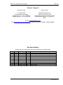
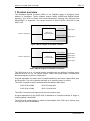
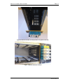
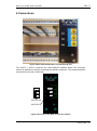
WOC-2-50-50-Mkll WOC-2-90-10-Mkll WOC-4-25-Mkll Wideband optical couplers User manual Rev. 0 Nevion HQ: Nevion Europe, P.O. Box 1020, 3204 Sandefjord, Norway Tel: +47 33 48 99 99 – Fax: +47 33 48 99 98 – www.nevion.com Rev. 0 WOC-2-xx-xx-Mkll, WOC-4-25-Mkll Nevion Support Nevion Europe Nevion USA P.O. Box 1020 3204 Sandefjord, Norway Support phone 1: +47 33 48 99 97 Support phone 2: +47 90 60 99 99 1600 Emerson Avenue Oxnard, CA 93033, USA Toll free North America: (866) 515-0811 Outside North America: +1 (805) 2478560 E-mail: [email protected] See http://www.nevion.com/support/ for service hours for customer support globally. Revision history Current revision of this document is the uppermost in the table below. Rev. Repl. Date 0 - 2012-05-23 Sign MR Change description Initial version nevion.com | 2 Rev. 0 WOC-2-xx-xx-Mkll, WOC-4-25-Mkll Contents Revision history .................................................................................................. 2 1 Product overview ............................................................................................. 4 2 Specifications .................................................................................................. 5 2.1 WOC-2-xx-xx .......................................................................................................... 5 2.1.1 Single mode fiber (9/125 um) .............................................................................. 5 2.2 WOC-4-25 .............................................................................................................. 6 2.2.1 Single mode fiber (9/125um) ............................................................................... 6 3 Mounting the CWDM module into frame ......................................................... 7 4 Connections .................................................................................................. 10 5 Laser safety precautions ............................................................................... 12 General environmental requirements for Nevion equipment ............................ 13 Product Warranty ............................................................................................. 14 Appendix A Materials declaration and recycling information ............................ 15 A.1 Materials declaration .............................................................................................15 A.2 Recycling information ............................................................................................15 EC Declaration of Conformity ........................................................................... 16 nevion.com | 3 Rev. 0 WOC-2-xx-xx-Mkll, WOC-4-25-Mkll 1 Product overview The Wideband Optical Couplers (WOC) in the Flashlink range is all-optical power splitters or combiners. These modules support WDM, CWDM and DWDM optical schemes. The WOC is bitrate and format transparent; meaning SDI, Ethernet and SDH/SONET is supported. The range consists of WOC-2-50-50, WOC-90-10 and WOC-4-25. X% of input Optical port 1 WOC-2-x-x Combiner/splitter Common optical port 100-X% of input Optical port 2 Figure 1 Block diagram of the WOC-2 module 25% of input Optical port 1 25% of input Common optical port WOC-4-25 Combiner/splitter Optical port 2 25% of input Optical port 3 25% of input Optical port 4 Figure 2 Block diagram of the WOC-4-25 module The WOC-2-xx-xx is a 1:2 optical coupler available with two different coupling ratios. And the WOC-4-25 is a 1:4 optical coupler, where the optical power is divided and distributed equally to the four output ports. A typical application for these units is multiple distribution and linear, tapped fiber optic bus structures. The unit is passive and there is no need for power or control. The WOC-2 optical coupler is available with two different split ratios: WOC-2-50-50-Mkll WOC-2-90-10-Mkll 50%-50% split ratio 90%-10% split ratio The WOC-2 has two input/output ports and one common port. A typical application for the WOC-4-25 is distribution to multiple locations of single or multiple signals using WDM. The WOC-4-25 optical coupler is made for wavelengths from 1260 up to 1620nm thus covering the whole CWDM band. nevion.com | 4 Rev. 0 WOC-2-xx-xx-Mkll, WOC-4-25-Mkll 2 Specifications 2.1 WOC-2-xx-xx 2.1.1 Single mode fiber (9/125 um) Optical passband: 1260-1620 nm Return loss: Directivity: Transmission circuit fiber: Connector: Better than 40 dB Better than 55 dB Single Mode Temperature range: 0 to +70°C (Operating) -40 to +85°C (Storage) Max. 300mW Power handling: SC/PC (Please be aware that SC/UPC is not an official standard though it is often used to specify better return loss parameters than SC/PC) Split ratios and corresponding maximum insertion loss (incl. connectors): WOC-2-50-50: 50 % / 50 % 4.3 dB / 4.3 dB (1260nm-1350mn and 1510-1620nm) 4.6 dB / 4.6 dB (1350nm-1510nm) WOC-2-90-10: 90 % / 10 % 1.33 dB / 11.7 dB (1260nm-1350mn and 1510-1620nm) 1.6 dB / 11.95 dB (1350nm-1510nm) nevion.com | 5 Rev. 0 WOC-2-xx-xx-Mkll, WOC-4-25-Mkll 2.2 WOC-4-25 2.2.1 Single mode fiber (9/125um) Optical passband: Return loss: Directivity: Transmission circuit fiber: Connector: 1260-1620 nm Better than 40 dB Better than 55 dB Single Mode Temperature range: 0 to +70°C (Operating) -40 to +85°C (Storage) Max. 300mW Power handling: SC/UP (Please be aware that SC/UPC is not an official standard though it is often used to specify better return loss parameters than SC/PC) Split ratio: 25%/25%/25%/25% Insertion loss with connectors: Max 9.0dB over the pass band. nevion.com | 6 WOC-2-xx-xx-Mkll, WOC-4-25-Mkll Rev. 0 3 Mounting the CWDM module into frame The CWDM filter must be mounted in a Flashlink sub rack. This is done from the rear. Do not use force when inserting the CWDM filter. The module’s main board has a special design to utilize both card rails in the FL sub rack. In order to enter the lower rail before sliding the unit into its final position, please follow the method shown in the pictures below. (Please note that the pictures show a not relevant product with similar mechanical solution). Figure 2 Enter the module with angle Figure 3 PCB tag inside the power bus PCB nevion.com | 7 WOC-2-xx-xx-Mkll, WOC-4-25-Mkll Rev. 0 Figure 4 Opposite side of PCB tag Figure 5 Adjust to normal position nevion.com | 8 WOC-2-xx-xx-Mkll, WOC-4-25-Mkll Rev. 0 Figure 6 Slide the module to final position using both card rails. Figure 7 Module mounted in frame nevion.com | 9 WOC-2-xx-xx-Mkll, WOC-4-25-Mkll Rev. 0 4 Connections Figure 8 WOC-2-50-50 Mounted in a Flashlink sub rack The WOC-2 / WOC-4 products are self-contained modules where the connector module is attached to the box protecting the optical component. The modules shall be mounted from the rear of the frame. WOC-50-50 WOC-90-10 Figure 9 Overview of the WOC-2 connector module nevion.com | 10 WOC-2-xx-xx-Mkll, WOC-4-25-Mkll Rev. 0 Figure 10 Overview of the WOC-4 connector module nevion.com | 11 Rev. 0 WOC-2-xx-xx-Mkll, WOC-4-25-Mkll 5 Laser safety precautions These are guidelines to limit hazards from laser exposure. All the available EO units in the Flashlink range include a laser. Therefore this note on laser safety should be read thoroughly even though there is no laser onboard this product. The lasers emit light at wave lengths between 1271 nm and 1611 nm. This means that the human eye cannot see the beam, and the blink reflex cannot protect the eye. (The human eye can see light between 400 nm to 700 nm). A laser beam can be harmful to the human eye (depending on laser power and exposure time). Therefore: Be careful when connecting / disconnecting fiber pigtails (ends). Never look directly into the pigtail of the laser/fiber. Never use microscopes, magnifying glasses or eye loupes to look into a fiber end. Use laser safety goggles blocking light between 1271 nm and at 1611 nm Instruments exist to verify light output power: Power meters, IR-cards etc. Flashlink features: The FR-2RU-10-2 is classified as Class 1 laser product according to EN 60 8251:94/A11:96, and CFR Ch1 (1997) Part 1040.10. If the front panel is removed, the FR-2RU-10-2 is classified as Class 1 laser product according to EN 60 825-1:94/A11:96, and class IIIb according to CFR Ch1 (1997) Part 1040.10. Maximum output power1: 17 mW Operating wavelengths: > 1260 nm 1 Max power is for safety analysis only and does not represent device performance. nevion.com | 12 Rev. 0 WOC-2-xx-xx-Mkll, WOC-4-25-Mkll General environmental requirements for Nevion equipment 1. 2. - The equipment will meet the guaranteed performance specification under the following environmental conditions: Operating room temperature 0°C to 50°C range: Operating relative humidity range: <90% (non-condensing) The equipment will operate without damage under the following environmental conditions: Temperature range: -10°C to 60°C Relative humidity range: <95% (non-condensing) nevion.com | 13 WOC-2-xx-xx-Mkll, WOC-4-25-Mkll Rev. 0 Product Warranty The warranty terms and conditions for the product(s) covered by this manual follow the General Sales Conditions by Nevion, which are available on the company web site: www.nevion.com nevion.com | 14 Rev. 0 WOC-2-xx-xx-Mkll, WOC-4-25-Mkll Appendix A Materials declaration and recycling information A.1 Materials declaration For product sold into China after 1st March 2007, we comply with the “Administrative Measure on the Control of Pollution by Electronic Information Products”. In the first stage of this legislation, content of six hazardous materials has to be declared. The table below shows the required information. Toxic or hazardous substances and elements 組成名稱 Part Name WOC-2-50-50-Mkll WOC-2-90-10-Mkll WOC-4-25-Mkll 鉛 汞 镉 六价铬 多溴联苯 多溴二苯醚 Lead Mercury Cadmium Hexavalent Polybrominated Polybrominated (Pb) (Hg) (Cd) Chromium biphenyls diphenyl ethers (Cr(VI)) (PBB) (PBDE) O O O O O O O: Indicates that this toxic or hazardous substance contained in all of the homogeneous materials for this part is below the limit requirement in SJ/T11363-2006. X: Indicates that this toxic or hazardous substance contained in at least one of the homogeneous materials used for this part is above the limit requirement in SJ/T11363-2006. This is indicated by the product marking: A.2 Recycling information Nevion provides assistance to customers and recyclers through our web site http://www.nevion.com/. Please contact Nevion’s Customer Support for assistance with recycling if this site does not show the information you require. Where it is not possible to return the product to Nevion or its agents for recycling, the following general information may be of assistance: Before attempting disassembly, ensure the product is completely disconnected from power and signal connections. All major parts are marked or labeled to show their material content. Depending on the date of manufacture, this product may contain lead in solder. Some circuit boards may contain battery-backed memory devices. nevion.com | 15 EC Declaration of Conformity MANUFACTURER Nevion AUTHORIZED REPRESENTATIVE (Established within the EEA) Not applicable MODEL NUMBER(S) WOC-2-50-50-Mkll WOC-2-90-10-Mkll WOC-4-25-Mkll DESCRIPTION Wideband optical couplers DIRECTIVES this equipment complies with Low voltage (EU Directive 2006/95/EC) EMC (EU Directive 2004/108/EC) RoHS (EU Directive 2002/95/EC) 2 China RoHS WEEE (EU Directive 2002/96/EC) REACH HARMONISED STANDARDS applied in order to verify compliance with Directive(s) EN 55103-1:1996 EN 55103-2:1996 EN 60950-1:2006 TEST REPORTS ISSUED BY Notified/Competent Body Report no: - - TECHNICAL CONSTRUCTION FILE NO Not applicable YEAR WHICH THE CE-MARK WAS AFFIXED 2011 TEST AUTHORIZED SIGNATORY MANUFACTURER AUTHORIZED REPRESENTATIVE (Established within EEA) Date of Issue 2011-03-30 Place of Issue Not applicable 2 Name Thomas Øhrbom Position VP of Business Support Systems, Nevion (authorized signature) Sandefjord, Norway Administration on the Control of Pollution Caused by Electronic Information Products Nevion HQ: Nevion Europe, P.O. Box 1020, 3204 Sandefjord, Norway Tel: +47 33 48 99 99 – Fax: +47 33 48 99 98 – www.nevion.com