1
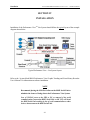
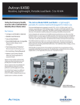
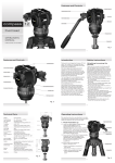
AVTRON MODEL K899
PERFORMANCE VIEWTM - LITE
Hardware Manual
© 2003 Avtron Manufacturing, Inc.
Cleveland, Ohio
September 5, 2003
Rev. Jan. 23, 2004
AVTRON MODEL K899
PERFORMANCE VIEWTM – LITE
Hardware Manual
TABLE OF CONTENTS
Page
Section
I
INTRODUCTION ………………………………………………………… 1-1
1.1 Overview.…………………………………………………………….. 1-1
II
SYSTEM DESCRIPTION ………………………………………………...
2.1 Collector/Viewer ……………………………………………………..
2.1.1 PC ……………………………………………………………..
2.1.2 UPS System …………………………………………………...
2.1.3 Printer …………………………………………………………
2.1.4 Additional Viewing Stations ………………………………….
2.1.4.1 Desktop Station ……………………………………...
2.1.4.2 Rack Mount Station ………………………………….
2.1.4.3 NEMA/Operator Station …………………….………
2.2 K885 Serial Interface Module (SIM) ………………………………...
2.3 Ethernet I/O Subsystem ………………………………………………
2-1
2-1
2-1
2-1
2-2
2-2
2-2
2-2
2-2
2-3
2-4
III
PREPARATION FOR USE ……………………………………………….
3.1 Environmental/Power Requirements …………………………………
3.1.1 Rack Mount/Desktop Equipment …………………………..…
3.1.2 NEMA Operator’s Station …………………………………….
3.1.3 Ethernet I/O System …………………………………………..
3-1
3-1
3-1
3-1
3-2
IV
INSTALLATION ………………………………………………………….
4.1 Desktop ………………………………………………………………
4.2 Rack Mount …………………………………………………………..
4.3 NEMA Operator’s Station ……………………………………………
4-1
4-2
4-2
4-2
V
TROUBLESHOOTING …………………………………………………...
5-1
VI
SUPPORTED COMMUNICATION PROTOCOLS ……………………..
6-1
PF/kv
i
AVTRON MODEL K899
PERFORMANCE VIEWTM – LITE
Hardware Manual
SECTION I
INTRODUCTION
1.1
OVERVIEW
The Avtron Model K899 Performance ViewTM Graphic Trending and Event History Recorder is a
software controlled device which provides complete monitoring and troubleshooting in support of
processes such as machine control systems, PLCs, and drive systems, including the Avtron
ADDvantage-32 Digital Drive. Diagnostic capabilities provide early notification and prioritization of
system irregularities, allowing for the application of preventive maintenance, rapid troubleshooting,
and reduced system downtime.
System data is acquired and communicated over an Ethernet network, allowing for real-time data
display, or recall (historical) display of stored data.
***********************************************************
CAUTION
Do NOT attempt to replace the operating system. Contact
Avtron's Service Department at 216-642-1230, Ext. 1255.
***********************************************************
CAUTION
Keep all manuals and software for all components of this
system in a safe location. Avtron is not responsible for
documentation/software of third party components of this
system.
***********************************************************
Performance View™ is a trademark of Avtron Mfg., Inc.
Modbus® is a registered trademark of Modicon, Inc.
1-1
Introduction
Avtron Model K899 Performance View™ - Lite – Hardware Manual
*********************************************************
WARNING
The operating software installed in the Avtron Performance
ViewTM is critical to the operation of the system. Installation or
operation of any other software programs, especially games or
screen savers, is prohibited and voids any and all warranties.
Installation or operation of other software programs may interfere
with the installed software, and damage to the components or
operation outside operational/safety rated limits may occur,
resulting in injury or death to personnel, and/or damage to attached
equipment.
*********************************************************
WARNING
Connection of external network devices to the system is strictly
prohibited without the consent of Avtron Mfg. Inc. Doing so will
void any and all warranties. Loss of network integrity/privacy may
result. Consult Avtron for proper design techniques that would not
jeopardize the network architecture integrity.
*********************************************************
WARNING
This system is a realtime data collection device. Do not attempt to
change the system clock or Time zone while the collection
software is running. Close the Performance ViewTM viewer first;
then shut down the Collector using the Stop_Collector icon. It is
now safe to change the time. Reboot the system when done.
*********************************************************
WARNING
If using the optional NEMA Operator’s Station, be sure to mount
the enclosure as specified before use.
*********************************************************
1-2
Avtron Model K899 Performance View™ - Lite – Hardware Manual
System Description
SECTION II
SYSTEM DESCRIPTION
2.1
COLLECTOR/VIEWER
Data acquisition and user interface is managed by the Performance ViewTM Lite Collector/Viewer.
The primary responsibilities of the Collector/Viewer station is to collect and store data from the
connected devices and provide the user interface.
2.1.1 PC
The Viewer PC incorporates a Windows® 2000 Professional Operating System and must contain at
minimum the following hardware:
•
•
•
•
•
•
•
•
•
•
•
•
2.26 GHz CPU, 533 MHz FSB, 512 L2 Cache
256 MB RDRam
20GB, 7200 RPM IDE hard drive
3.25” floppy disk drive
56 KB Internal Phone Modem
10/100T Network Interface Card
(Qty. 5) PCI expansion slots
10/100/1000T Embedded Network Interface Card
19” Color CRT Monitor
Windows Keyboard
Standard Mouse
19” rack mount form factor, 2U height, with rails for server rack
(for rack mount configuration only)
2.1.2 UPS SYSTEM
The Uninterruptible Power Supply (UPS) is a device that sits between a power supply (e.g. a wall
outlet) and a device (e.g. a computer) to prevent undesired characteristics of the power supply
(outages, sags, surges, bad harmonics, etc.) from the supply from adversely affecting the performance
of the device. The UPS system used for this system should have 700VA minimum capacity and
support serial connection to the host computer.
The UPS system is also used to intelligently shut down the Collector/Viewer in such a way as not to
corrupt any of the database files.
DO NOT attempt to operate the Collector/Viewer without a properly configured UPS.
2-1
System Description
Avtron Model K899 Performance View™ - Lite – Hardware Manual
2.1.3 PRINTER
HP Inkjet 5850 desktop color printer, or equivalent, used to print real-time or historical representation
of data and graphical trending screens.
2.1.4 ADDITIONAL VIEWING STATIONS
Multiple viewing stations may be added to the network. Each viewing station must be composed of a
PC, monitor, keyboard and mouse.
2.1.4.1 Desktop Station
An additional desktop viewing station may be added to the Performance ViewTM Lite system as an
option. The additional viewing station requires an additional desktop PC (the same minimum
requirements listed in section 2.1.1 above), 19” monitor, keyboard, and mouse.
2.1.4.2
Rack Mount Station
An additional desktop viewing station may be added to the Performance ViewTM Lite system as an
option. The additional viewing station requires an additional rack mount PC (the same minimum
requirements listed in section 2.1.1 above), 19” monitor, keyboard, and mouse.
2.1.4.3
NEMA Operator Station
The add-on NEMA operator station can extend a viewing station out to the factory floor in place of
the 19” CRT monitor and keyboard. This station utilizes a NEMA 4x, 18.1”, TFT, flat panel monitor,
NEMA 4x panel mount keyboard with hula point device, and choice of NEMA 12 or 4x enclosure.
The viewing station can extend out on the factory floor from the viewing station PC (located within a
control room) from 500 to 1000ft using a KVM extender. The NEMA enclosure can be manufactured
for wall or pedestal mount configurations depending on application.
2-2
System Description
2.2
Avtron Model K899 Performance View™ - Lite – Hardware Manual
K885 SERIAL INTERFACE MODULE (SIM)
The K885 Serial Interface Module (SIM) is an Avtron manufactured device that allows devices
supporting RS-232 to “tap” into the Avtron K885 Serial Link used by the K885 systems. The SIM
provides an interface for the Collector to capture real-time data off of the SISL from the K885 DCU.
The K885 SIM is connected to the Collector/Viewer PC via a RS-232 cable to the COM port of the
PC (interface to K885 Serial Link is shown below).
2-3
System Description
Avtron Model K899 Performance View™ - Lite – Hardware Manual
Data acquisition is achieved using the Avtron K885 OPC Server; refer to the “Avtron Model K899
Performance ViewTM User’s Manual” for additional information.
2.3
ETHERNET I/O SUBSYSTEM
An optional Ethernet remote I/O system may also be added to the Performance ViewTM System. This
interface can be made using a Network Interface Unit (NIU), supporting EGD protocol only, which
may support up to eight of the following available I/O modules per NIU:
o
o
o
o
o
o
o
o
o
16 points, 120VAC discrete input isolated
16 points, 120VAC discrete (2 groups of 8 points)
16 points, 24VDC discrete (2 groups of 8 points)
8 channel 16-bit analog input (voltage/current)
8 channel 12-bit analog input (voltage/current)
8 channel 15-bit analog differential voltage input
8 channel 15-bit analog differential current input
15 channel, 15-bit analog voltage input
15 channel, 15-bit analog current input
All I/O modules are DIN rail mountable include the NIU interface module.
2-4
System Description
Avtron Model K899 Performance View™ - Lite – Hardware Manual
Additional information on the optional Ethernet I/O system may be found in the “Avtron Supported
GE Fanuc Automation Programmable Control Products: VersaMax® Modules, Power Supplies, and
Carriers” supplement to this manual.
2-5
Avtron Model K899 Performance View™ - Lite – Hardware Manual
Preparation for Use
SECTION III
PREPARATION FOR USE
3.1
ENVIRONMENTAL/POWER REQUIREMENTS
Before using any of the components for this system, ensure the following environmental and power
requirements are within the recommended ranges.
3.1.1
RACK MOUNT/DESKTOP EQUIPMENT
The listed environmental conditions must be kept within the following limits for all components with
exception to the optional NEMA Operator’s Station and the optional Ethernet I/O system.
•
•
•
•
•
•
•
•
•
•
•
Operating Temperature: 10º C to 35º C (50º F to 95º F)
Storage Temperature: -40º C to 65º C (-40º F to 149º F)
Operating Relative Humidity: 8% to 80% non-condensing
Storage Relative Humidity: 5% to 95% non-condensing
Operating Vibration: 0.25G at 3Hz to 200Hz for 15 minutes
Storage Vibration: 0.5G at 3Hz to 200Hz for 15 minutes
Operating Shock: 6 shock pulses of 50G for up to 2ms
Storage Shock: 6 shock pulses of 92G for up to 2ms
Operating Altitude: -16m to 3,048m (-50 ft to 10,000 ft)
Storage Altitude: -16m to 10,600m (-50 ft to 35,000 ft)
Operating Air Quality: Dust-free, office-grade air required for ventilation
3.1.2 NEMA OPERATOR’S STATION
The environmental conditions of the NEMA enclosure must be within the following range:
•
•
•
•
•
•
•
•
•
•
Operating Temperature: 0º C to 40º C (32º F to 104º F)
0º C to 55º C (32º F to 131º F) with optional cooling unit installed on enclosure
Storage Temperature: -20º C to 50º C (-4º F to 122º F)
Operating Relative Humidity: 20% to 80% non-condensing
Storage Relative Humidity: 20% to 80% non-condensing
Operating Vibration: 1.0G at 5Hz to 2000Hz
Storage Vibration: 2.5G at 5Hz to 2000Hz
Operating Shock: 15G for up to 11ms
Storage Shock: 30G for up to 11ms
Operating Altitude: 0m to 3,048m (0 ft to 10,000 ft)
Storage Altitude: 0m to 12,192m (0 ft to 40,000 ft)
3-1
Preparation for Use
Avtron Model K899 Performance View™ - Lite – Hardware Manual
The power requirement must be within the following range:
•
AC Power: 100 VAC to 240 VAC, 1.0 A, 50/60 Hz
3.1.3 ETHERNET I/O SYSTEM
Refer to the “Avtron Manufacturing Supported GE Fanuc Automation Programmable Control
Products VersaMax® Modules, Power Supplies, and Carriers” supplement to this manual for
environmental and power specifications.
3-2
Installation
Avtron Model K899 Performance View™ - Lite – Hardware Manual
SECTION IV
INSTALLATION
Installation of the Performance ViewTM Lite System should follow the typical layout of the example
diagram shown below:
Typical Performance View – Lite System Layout
Refer to the “Avtron Model K899 Performance View Graphic Trending and Event History Recorder
User’s Manual” for information on software installation.
NOTE
Recommend placing the SIM first in line on the K885 Serial Link to
minimize the chance of losing data to the Performance View System.
Loss of 120VAC power to the SIM or PC, or removal of the serial
communications connection (K885 Serial Link or RS 232) will break
the K885 Serial Link resulting in loss of serial communication to other
devices downstream on the K885 Serial Link.
4-1
Installation
4.1
Avtron Model K899 Performance View™ - Lite – Hardware Manual
DESKTOP
The hardware installation of the Performance ViewTM Lite desktop configuration can be performed as
shown in included drawings (refer to wiring drawings included in drawing packet for details).
4.2
RACK MOUNT
The hardware installation of the Performance ViewTM Lite rack mount configuration can be
performed as shown in included drawings (refer to wiring drawings included in drawing packet for
details).
4.3
NEMA OPERATOR’S STATION
To provide a user interface to the Performance ViewTM Lite system on the factory floor the NEMA
Operator’s Station option may be used to take the place of the monitor, keyboard, and mouse
components of the desktop configuration. The installation of the NEMA Operator’s Station can be
completed as shown in included drawings (refer to wiring drawings included in drawing packet for
details).
4-2
Troubleshooting
Avtron Model K899 Performance View™ - Lite – Hardware Manual
SECTION V
TROUBLESHOOTING
For questions or problems regarding the Avtron K885 Serial Link, refer to the “AVTRON MODEL
K885 DIGITAL SPEED & DRAW SYSTEM” manual.
For all other questions or problems, refer to the Frequently Asked Questions (FAQ) under the
Performance View link on the Avtron website (www.avtron.com) or call Avtron support.
5-1
Supported Communication Protocols
Avtron Model K899 Performance View™ - Lite – Hardware Manual
SECTION VI
SUPPORTED COMMUNICATION PROTOCOLS
The following protocols are supported for logging data from optional customer-supplied 3rd party
devices and for communicating data to optional customer supplied 3rd party devices:
o
Modbus TCP/IP – Ethernet Modbus TCP/IP protocol utilizes the Ethernet RJ-45 network
interface port on the Collector/Viewer PC.
o
Ethernet Global Data (EGD) – EGD protocol utilizes the Ethernet RJ-45 network interface
port on the Collector/Viewer PC.
o
Ethernet/IP Explicit Messaging – Ethernet IP protocol utilizes the Ethernet RJ-45 network
interface port on the Collector/Viewer PC.
o
Rockwell Automation PLC-5 (CSP) – Ethernet CSP protocol utilizes the Ethernet RJ-45
network interface port on the Collector/Viewer PC.
o
Rockwell Automation SLC/05 (CSP) – Ethernet CSP protocol utilizes the Ethernet RJ-45
network interface port on the Collector/Viewer PC.
o
GE Fanuc CCM – The CCM protocol utilizes the RS-232 serial COM port on the
Collector/Viewer PC.
o
GE Fanuc SNP – The SNP protocol utilizes the RS-232 serial COM port on the
Collector/Viewer PC.
o
GE Fanuc 90-30/90-70 Ethernet – 90-30/90-70 Ethernet protocol utilizes the Ethernet RJ-45
network interface port on the Collector/Viewer PC.
o
Modicon Modbus Serial – Modicon Modbus Serial protocol utilizes the RS-232 serial COM
port on the Collector/Viewer PC.
o
Modicon Modbus Plus (MB+) – Modicon Modbus Plus protocol utilizes the port of a SA85
interface card installed in an auxiliary PCI slot in the Collector/Viewer PC.
o
OPC Server Interface – Consult Avtron for available options.
Consult Avtron for availability of any other custom protocols.
6-1