1
Glove is in the air
Project report
Authors: Øyvind Bø Syrstad, Erik Rogstad, Trond Valen, Frode Ingebrigtsen, Lars-Erik
Bjørk, Stein Jakob Nordbø
Version: 1.0
Executive summary
Glove is in the air is a project carried out as part of the course TDT4290 Customer Driven Project
at Institute of Informatics and Computer Science, NTNU, during the autumn 2004. There are
six project members, all from class SIF2, Computer Science. The customer for for this project is
the Chemometrics and Bioinformatics Group at the Institute of Chemistry, NTNU. Their goal is
development of a library for integration with the software data analysis tool SciCraft. In addition,
the customer wants an application demonstrating the capabilities of this library.
The purpose of Glisa is to enable a pair of electronic gloves to be used for control of virtual reality
applications, and it should support both movement and rotation of either hand, as well as measurements of finger flexure. The intended use of these gloves, and the library, is to enable interaction with
a virtual environment without using conventional input devices like keyboard and mice. In particular,
the customer envisioned integration with SciCraft to perform tasks such as molecule building and
interaction with plots from analysis of large sets of data. The demonstration application is supposed
to build confidence in that gloves as input devices would be a helpful addition to 3D applications.
In order to determine the needs of the customer and the best way to fulfill these, a prestudy has been
conducted. The prestudy revealed that the functionality of the library would need to span from basic
communication with the input devices to advanced features such as gesture recognition. Moreover, it
became evident that the demonstration application should display a virtual environment scene and
enable the user to use the gloves to manipulate objects in this scene.
The prestudy lead to a software requirements specification that made up the foundation for system
design, implementation and testing. At the end of the project, a library has been created that enables
interaction with a 3D scene, and that forms the foundation for further research and development,
towards a final integration with SciCraft.
Lars−Erik Bjørk
Frode Ingebrigtsen
Erik Rogstad
TDT4290 Customer Driven Project, group 11
Trond Valen
Stein Jakob Nordbø
Øyvind Bø Syrstad
i
Contents
I
Project Directive
2
1 Introduction
5
2 Project charter
6
2.1
Project name . . . . . . . . . . . . . . . . . . . . . . . . . . . . . . . . . . . . . . . . .
6
2.2
Employer . . . . . . . . . . . . . . . . . . . . . . . . . . . . . . . . . . . . . . . . . . .
6
2.3
Stakeholders . . . . . . . . . . . . . . . . . . . . . . . . . . . . . . . . . . . . . . . . . .
6
2.4
Background . . . . . . . . . . . . . . . . . . . . . . . . . . . . . . . . . . . . . . . . . .
7
2.5
Output objectives
. . . . . . . . . . . . . . . . . . . . . . . . . . . . . . . . . . . . . .
7
2.6
Result objectives . . . . . . . . . . . . . . . . . . . . . . . . . . . . . . . . . . . . . . .
7
2.7
Purpose . . . . . . . . . . . . . . . . . . . . . . . . . . . . . . . . . . . . . . . . . . . .
7
2.8
Feasibility of the project . . . . . . . . . . . . . . . . . . . . . . . . . . . . . . . . . . .
8
2.9
Scope of the project . . . . . . . . . . . . . . . . . . . . . . . . . . . . . . . . . . . . .
8
2.10 External conditions . . . . . . . . . . . . . . . . . . . . . . . . . . . . . . . . . . . . . .
9
2.11 Budget . . . . . . . . . . . . . . . . . . . . . . . . . . . . . . . . . . . . . . . . . . . . . 10
2.12 Deliveries . . . . . . . . . . . . . . . . . . . . . . . . . . . . . . . . . . . . . . . . . . . 10
3 Project plan
TDT4290 Customer Driven Project, group 11
11
ii
3.1
Success criteria . . . . . . . . . . . . . . . . . . . . . . . . . . . . . . . . . . . . . . . . 11
3.2
Risks . . . . . . . . . . . . . . . . . . . . . . . . . . . . . . . . . . . . . . . . . . . . . . 11
3.3
Work breakdown structure . . . . . . . . . . . . . . . . . . . . . . . . . . . . . . . . . . 12
4 Organization
14
5 Templates and standards
15
5.1
Templates . . . . . . . . . . . . . . . . . . . . . . . . . . . . . . . . . . . . . . . . . . . 15
5.2
File naming and directory structure . . . . . . . . . . . . . . . . . . . . . . . . . . . . 15
6 Version control
18
7 Project follow up
19
7.1
Meetings . . . . . . . . . . . . . . . . . . . . . . . . . . . . . . . . . . . . . . . . . . . . 19
7.2
Internal reporting . . . . . . . . . . . . . . . . . . . . . . . . . . . . . . . . . . . . . . . 20
7.3
Status reporting . . . . . . . . . . . . . . . . . . . . . . . . . . . . . . . . . . . . . . . 20
7.4
Project management . . . . . . . . . . . . . . . . . . . . . . . . . . . . . . . . . . . . . 20
8 Quality assurance
21
8.1
Response times with the customer . . . . . . . . . . . . . . . . . . . . . . . . . . . . . 21
8.2
Routines for producing quality from the start . . . . . . . . . . . . . . . . . . . . . . . 21
8.3
Routines for approval of phase documents . . . . . . . . . . . . . . . . . . . . . . . . . 22
8.4
Calling a meeting with the customer . . . . . . . . . . . . . . . . . . . . . . . . . . . . 22
8.5
Reports from the customer meetings . . . . . . . . . . . . . . . . . . . . . . . . . . . . 22
8.6
Calling a meeting with the tutors . . . . . . . . . . . . . . . . . . . . . . . . . . . . . . 22
TDT4290 Customer Driven Project, group 11
iii
8.7
Agenda for meetings with the tutors . . . . . . . . . . . . . . . . . . . . . . . . . . . . 23
8.8
Report from the last meeting with the tutors . . . . . . . . . . . . . . . . . . . . . . . 23
8.9
Routines for the distribution of information and documentation . . . . . . . . . . . . . 23
8.10 Routines for registering costs (working-hours) . . . . . . . . . . . . . . . . . . . . . . . 23
9 Test documentation
II
24
9.1
Module test . . . . . . . . . . . . . . . . . . . . . . . . . . . . . . . . . . . . . . . . . . 24
9.2
System test . . . . . . . . . . . . . . . . . . . . . . . . . . . . . . . . . . . . . . . . . . 25
9.3
Usability test . . . . . . . . . . . . . . . . . . . . . . . . . . . . . . . . . . . . . . . . . 25
Prestudy
27
10 Introduction
31
11 Description of the customer
33
11.1 NTNU . . . . . . . . . . . . . . . . . . . . . . . . . . . . . . . . . . . . . . . . . . . . . 33
11.2 The Chemometrics and Bioinformatics Group . . . . . . . . . . . . . . . . . . . . . . . 34
12 Glove is in the air - what is it?
35
13 Operational requirements
36
14 Evaluation criteria
37
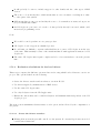
14.1 Evaluation criteria for low level drivers . . . . . . . . . . . . . . . . . . . . . . . . . . . 38
14.2 Evaluation criteria for the middleware level . . . . . . . . . . . . . . . . . . . . . . . . 38
14.3 Evaluation criteria for application level (graphics package) . . . . . . . . . . . . . . . . 38
TDT4290 Customer Driven Project, group 11
iv
15 Theory
39
15.1 Virtual reality . . . . . . . . . . . . . . . . . . . . . . . . . . . . . . . . . . . . . . . . . 39
15.2 Display devices . . . . . . . . . . . . . . . . . . . . . . . . . . . . . . . . . . . . . . . . 39
15.3 Human computer interface devices . . . . . . . . . . . . . . . . . . . . . . . . . . . . . 40
16 Description of the existing system
41
16.1 SciCraft . . . . . . . . . . . . . . . . . . . . . . . . . . . . . . . . . . . . . . . . . . . . 41
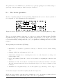
16.2 5DT Data Glove 5 . . . . . . . . . . . . . . . . . . . . . . . . . . . . . . . . . . . . . . 42
16.3 Flock of Birds . . . . . . . . . . . . . . . . . . . . . . . . . . . . . . . . . . . . . . . . . 43
16.4 Hololib . . . . . . . . . . . . . . . . . . . . . . . . . . . . . . . . . . . . . . . . . . . . . 45
17 Alternative solutions
46
17.1 Low level drivers . . . . . . . . . . . . . . . . . . . . . . . . . . . . . . . . . . . . . . . 46
17.2 The middleware . . . . . . . . . . . . . . . . . . . . . . . . . . . . . . . . . . . . . . . . 53
17.3 The application layer . . . . . . . . . . . . . . . . . . . . . . . . . . . . . . . . . . . . . 60
17.4 Programming languages . . . . . . . . . . . . . . . . . . . . . . . . . . . . . . . . . . . 64
18 Conclusion
66
18.1 Low level drivers . . . . . . . . . . . . . . . . . . . . . . . . . . . . . . . . . . . . . . . 66
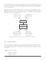
18.2 Middleware solutions . . . . . . . . . . . . . . . . . . . . . . . . . . . . . . . . . . . . . 66
18.3 Application layer solution . . . . . . . . . . . . . . . . . . . . . . . . . . . . . . . . . . 67
III
Requirements Specification
19 Introduction
TDT4290 Customer Driven Project, group 11
68
71
v
19.1 Purpose . . . . . . . . . . . . . . . . . . . . . . . . . . . . . . . . . . . . . . . . . . . . 71
19.2 Scope . . . . . . . . . . . . . . . . . . . . . . . . . . . . . . . . . . . . . . . . . . . . . 71
19.3 Overview . . . . . . . . . . . . . . . . . . . . . . . . . . . . . . . . . . . . . . . . . . . 72
20 Overall description
73
20.1 Product perspective . . . . . . . . . . . . . . . . . . . . . . . . . . . . . . . . . . . . . 73
20.2 Product functions . . . . . . . . . . . . . . . . . . . . . . . . . . . . . . . . . . . . . . . 75
20.3 User characteristics . . . . . . . . . . . . . . . . . . . . . . . . . . . . . . . . . . . . . . 76
21 Functional requirements
77
21.1 Application specific functional requirements . . . . . . . . . . . . . . . . . . . . . . . . 79
21.2 Support application specific requirements . . . . . . . . . . . . . . . . . . . . . . . . . 87
21.3 Middleware specific requirements . . . . . . . . . . . . . . . . . . . . . . . . . . . . . . 88
22 Non-functional requirements
96
22.1 Performance characteristics . . . . . . . . . . . . . . . . . . . . . . . . . . . . . . . . . 96
22.2 Design constraints . . . . . . . . . . . . . . . . . . . . . . . . . . . . . . . . . . . . . . 96
22.3 Maintainability . . . . . . . . . . . . . . . . . . . . . . . . . . . . . . . . . . . . . . . . 97
22.4 Portability . . . . . . . . . . . . . . . . . . . . . . . . . . . . . . . . . . . . . . . . . . . 97
23 Required documentation
98
23.1 System documentation . . . . . . . . . . . . . . . . . . . . . . . . . . . . . . . . . . . . 98
23.2 API documentation . . . . . . . . . . . . . . . . . . . . . . . . . . . . . . . . . . . . . . 99
23.3 Installation manual . . . . . . . . . . . . . . . . . . . . . . . . . . . . . . . . . . . . . . 99
23.4 User manual . . . . . . . . . . . . . . . . . . . . . . . . . . . . . . . . . . . . . . . . . . 99
TDT4290 Customer Driven Project, group 11
vi
IV
Construction Documentation
100
24 Introduction
103
25 Architecture of Glisa
104
25.1 Overview of design . . . . . . . . . . . . . . . . . . . . . . . . . . . . . . . . . . . . . . 104
26 Development plan
107
26.1 Incremental development model . . . . . . . . . . . . . . . . . . . . . . . . . . . . . . . 107
26.2 Scope of each increment . . . . . . . . . . . . . . . . . . . . . . . . . . . . . . . . . . . 107
26.3 Schedule . . . . . . . . . . . . . . . . . . . . . . . . . . . . . . . . . . . . . . . . . . . . 108
27 Description of the increments
109
27.1 Increment 1 . . . . . . . . . . . . . . . . . . . . . . . . . . . . . . . . . . . . . . . . . . 109
27.2 Increment 2 . . . . . . . . . . . . . . . . . . . . . . . . . . . . . . . . . . . . . . . . . . 113
27.3 Increment 3 . . . . . . . . . . . . . . . . . . . . . . . . . . . . . . . . . . . . . . . . . . 115
28 Programming methods and tools
120
28.1 Development environment . . . . . . . . . . . . . . . . . . . . . . . . . . . . . . . . . . 120
28.2 Unit Testing . . . . . . . . . . . . . . . . . . . . . . . . . . . . . . . . . . . . . . . . . . 121
28.3 Source code verifiers . . . . . . . . . . . . . . . . . . . . . . . . . . . . . . . . . . . . . 124
28.4 Debugging tools . . . . . . . . . . . . . . . . . . . . . . . . . . . . . . . . . . . . . . . . 125
28.5 C/C++ to python binding generator . . . . . . . . . . . . . . . . . . . . . . . . . . . . 126
TDT4290 Customer Driven Project, group 11
vii
V
Implementation
128
29 Introduction
131
30 System documentation
132
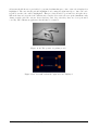
30.1 Demo Application . . . . . . . . . . . . . . . . . . . . . . . . . . . . . . . . . . . . . . 132
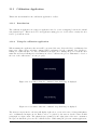
30.2 Calibration application system documentation . . . . . . . . . . . . . . . . . . . . . . . 135
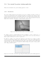
30.3 System documentation for the gesture training application . . . . . . . . . . . . . . . . 137
30.4 System documentation for the middleware . . . . . . . . . . . . . . . . . . . . . . . . . 138
30.5 System documentation for the lowlevel . . . . . . . . . . . . . . . . . . . . . . . . . . . 143
31 User Manuals
148
31.1 Installation manual . . . . . . . . . . . . . . . . . . . . . . . . . . . . . . . . . . . . . . 148
31.2 Demo application . . . . . . . . . . . . . . . . . . . . . . . . . . . . . . . . . . . . . . . 150
31.3 Calibration Application . . . . . . . . . . . . . . . . . . . . . . . . . . . . . . . . . . . 155
31.4 User manual for gesture training application . . . . . . . . . . . . . . . . . . . . . . . . 157
32 Coding guidelines
160
32.1 Python code . . . . . . . . . . . . . . . . . . . . . . . . . . . . . . . . . . . . . . . . . . 161
32.2 C/C++ code . . . . . . . . . . . . . . . . . . . . . . . . . . . . . . . . . . . . . . . . . 163
VI
Test Documentation
165
33 Introduction
169
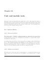
34 Unit and module tests
170
TDT4290 Customer Driven Project, group 11
viii
34.1 Low-level drivers . . . . . . . . . . . . . . . . . . . . . . . . . . . . . . . . . . . . . . . 170
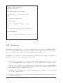
34.2 Middleware . . . . . . . . . . . . . . . . . . . . . . . . . . . . . . . . . . . . . . . . . . 171
34.3 Applications and support applications . . . . . . . . . . . . . . . . . . . . . . . . . . . 172
35 System test
173
35.1 Goal . . . . . . . . . . . . . . . . . . . . . . . . . . . . . . . . . . . . . . . . . . . . . . 173
35.2 Test specification . . . . . . . . . . . . . . . . . . . . . . . . . . . . . . . . . . . . . . . 173
35.3 Conclusion . . . . . . . . . . . . . . . . . . . . . . . . . . . . . . . . . . . . . . . . . . 174
36 Acceptance test
179
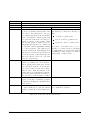
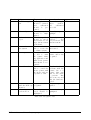
36.1 Acceptance Test - results and errors . . . . . . . . . . . . . . . . . . . . . . . . . . . . 179
37 Usability test
181
37.1 Goal . . . . . . . . . . . . . . . . . . . . . . . . . . . . . . . . . . . . . . . . . . . . . . 181
37.2 Time and place . . . . . . . . . . . . . . . . . . . . . . . . . . . . . . . . . . . . . . . . 181
37.3 Setup . . . . . . . . . . . . . . . . . . . . . . . . . . . . . . . . . . . . . . . . . . . . . 181
37.4 Roles . . . . . . . . . . . . . . . . . . . . . . . . . . . . . . . . . . . . . . . . . . . . . . 182
37.5 Test tasks . . . . . . . . . . . . . . . . . . . . . . . . . . . . . . . . . . . . . . . . . . . 183
37.6 Conclusion . . . . . . . . . . . . . . . . . . . . . . . . . . . . . . . . . . . . . . . . . . 183
VII
Evaluation
185
38 Introduction
191
39 Cause analysis
193
39.1 Time . . . . . . . . . . . . . . . . . . . . . . . . . . . . . . . . . . . . . . . . . . . . . . 193
TDT4290 Customer Driven Project, group 11
ix
39.2 Design . . . . . . . . . . . . . . . . . . . . . . . . . . . . . . . . . . . . . . . . . . . . . 194
39.3 Requirements . . . . . . . . . . . . . . . . . . . . . . . . . . . . . . . . . . . . . . . . . 194
39.4 Documentation . . . . . . . . . . . . . . . . . . . . . . . . . . . . . . . . . . . . . . . . 194
39.5 Cooperation . . . . . . . . . . . . . . . . . . . . . . . . . . . . . . . . . . . . . . . . . . 195
39.6 Retrieved knowledge . . . . . . . . . . . . . . . . . . . . . . . . . . . . . . . . . . . . . 195
40 Time usage
196
41 Resource evaluation
197
42 Fulfillment of success criteria
198
43 Remaining work
199
44 Future possibilities
200
A Project activities
201
B Templates
212
B.1 Summons . . . . . . . . . . . . . . . . . . . . . . . . . . . . . . . . . . . . . . . . . . . 212
B.2 Status report . . . . . . . . . . . . . . . . . . . . . . . . . . . . . . . . . . . . . . . . . 213
B.3 Minutes . . . . . . . . . . . . . . . . . . . . . . . . . . . . . . . . . . . . . . . . . . . . 215
B.4 Phase documents . . . . . . . . . . . . . . . . . . . . . . . . . . . . . . . . . . . . . . . 216
C Stakeholders
217
D Risk table
218
E Abbreviations and terms
223
TDT4290 Customer Driven Project, group 11
x
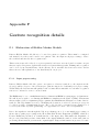
F Gesture recognition details
225
F.1 Elaboration of Hidden Markov Models . . . . . . . . . . . . . . . . . . . . . . . . . . . 225
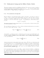
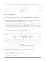
F.2 Mathematical background for Hidden Markov Models . . . . . . . . . . . . . . . . . . 229
F.3 The Vector Quantiser . . . . . . . . . . . . . . . . . . . . . . . . . . . . . . . . . . . . 233
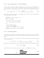
F.4 The Short-Time Fourier Transform . . . . . . . . . . . . . . . . . . . . . . . . . . . . . 234
G 5DT Data Glove 5: Technical details
236
G.1 Data transfer . . . . . . . . . . . . . . . . . . . . . . . . . . . . . . . . . . . . . . . . . 237
G.2 Driver functions . . . . . . . . . . . . . . . . . . . . . . . . . . . . . . . . . . . . . . . . 237
H Flock of Birds: Technical details
239
H.1 The basic commands . . . . . . . . . . . . . . . . . . . . . . . . . . . . . . . . . . . . . 239
H.2 Technical specifications
. . . . . . . . . . . . . . . . . . . . . . . . . . . . . . . . . . . 240
Abbreviations and terms
241
J File format specifications
242
I
J.1
glisa.xml specification . . . . . . . . . . . . . . . . . . . . . . . . . . . . . . . . . . . 242
J.2
gesture_db.xml specification . . . . . . . . . . . . . . . . . . . . . . . . . . . . . . . . 243
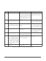
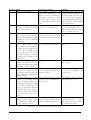
K Usability test tasks
245
K.1 Gesture training application usability test . . . . . . . . . . . . . . . . . . . . . . . . . 245
K.2 Demo application usability test . . . . . . . . . . . . . . . . . . . . . . . . . . . . . . . 247
K.3 Package demo . . . . . . . . . . . . . . . . . . . . . . . . . . . . . . . . . . . . . . . . . 249
K.4 Module demo.graphics . . . . . . . . . . . . . . . . . . . . . . . . . . . . . . . . . . . . 249
TDT4290 Customer Driven Project, group 11
xi
K.5 Module demo.objects . . . . . . . . . . . . . . . . . . . . . . . . . . . . . . . . . . . . . 254
K.6 Package glisa . . . . . . . . . . . . . . . . . . . . . . . . . . . . . . . . . . . . . . . . . 254
K.7 Package glisa.calibrator . . . . . . . . . . . . . . . . . . . . . . . . . . . . . . . . . . . 256
K.8 Module glisa.calibrator.calibrate . . . . . . . . . . . . . . . . . . . . . . . . . . . . . . 257
K.9 Package glisa.gesttraining . . . . . . . . . . . . . . . . . . . . . . . . . . . . . . . . . . 258
K.10 Package glisa.middleware . . . . . . . . . . . . . . . . . . . . . . . . . . . . . . . . . . 258
K.11 Module glisa.middleware.control . . . . . . . . . . . . . . . . . . . . . . . . . . . . . . 259
K.12 Module glisa.middleware.gestrec . . . . . . . . . . . . . . . . . . . . . . . . . . . . . . 260
K.13 Module glisa.middleware.input3d . . . . . . . . . . . . . . . . . . . . . . . . . . . . . . 263
L Glove is in the air lowlevel API
267
L.1 Glove is in the air: Lowlevel Hierarchical Index . . . . . . . . . . . . . . . . . . . . . . 267
L.2 Glove is in the air: Lowlevel Class Index . . . . . . . . . . . . . . . . . . . . . . . . . . 267
L.3 Glove is in the air: Lowlevel Class Documentation . . . . . . . . . . . . . . . . . . . . 268
Bibliography
TDT4290 Customer Driven Project, group 11
286
xii
List of Figures
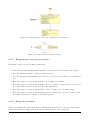
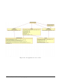
11.1 Organization chart of NTNU [Dah04] . . . . . . . . . . . . . . . . . . . . . . . . . . . . 33
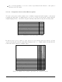
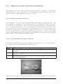
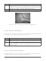
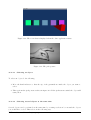
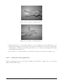
16.1 The existing configuration of Flock of Birds at the Institute of Chemistry . . . . . . . 44
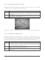
16.2 The desired configuration of Flock of Birds at the Institute of Chemistry . . . . . . . . 45
17.1 The architecture of VR Juggler (source: [Tea04a] . . . . . . . . . . . . . . . . . . . . . 47
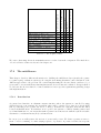
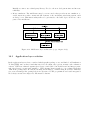
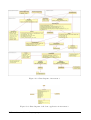
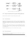
17.2 Middleware layer architecture . . . . . . . . . . . . . . . . . . . . . . . . . . . . . . . . 54
18.1 Middleware layer architecture (copy of figure 17.2) . . . . . . . . . . . . . . . . . . . . 67
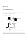
20.1 The setup of the computer and the other physical devices . . . . . . . . . . . . . . . . 73
20.2 Overview of the parts of the system that work together . . . . . . . . . . . . . . . . . 74
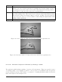
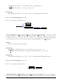
21.1 The posture for switching from 3D mode to 2D mode as described in requirement A-1
79
21.2 The posture for switching from 2D mode to 3D mode as described in requirement A-2
80
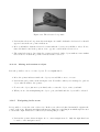
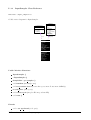
21.3 Extended index finger in the posture left clicking as described in requirement A-3 . . . 81
21.4 Flexed index finger in the posture for left clicking as described in requirement A-3 . . 81
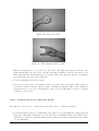
21.5 Extended thumb in the posture right clicking as described in requirement A-4 . . . . . 82
21.6 Flexed thumb in the posture for right clicking as described in requirement A-4 . . . . 82
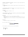
21.7 Posture for doing a gesture as described in requirement A-6 . . . . . . . . . . . . . . . 83
TDT4290 Customer Driven Project, group 11
xiii
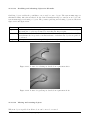
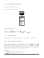
21.8 One posture for doing a selection as described in requirement A-8 . . . . . . . . . . . . 84
21.9 Another posture for doing a selection as described in requirement A-8 . . . . . . . . . 84
21.10Connected index fingers as described in requirement A-9 . . . . . . . . . . . . . . . . . 85
21.11Index fingers moving apart as described in requirement A-9 . . . . . . . . . . . . . . . 85
21.12Posture for setting the box size final as described in requirement A-9 . . . . . . . . . . 85
21.13Posture for releasing as described in requirement A-10 . . . . . . . . . . . . . . . . . . 86
21.14Posture for grabbing as described in requirement A-10 . . . . . . . . . . . . . . . . . . 86
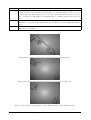
21.15Built-in gesture as described in requirement M-5 . . . . . . . . . . . . . . . . . . . . . 90
21.16Built-in gesture as described in requirement M-5 . . . . . . . . . . . . . . . . . . . . . 91
21.17Built-in gesture as described in requirement M-5 . . . . . . . . . . . . . . . . . . . . . 91
21.18Built-in gesture as described in requirement M-5 . . . . . . . . . . . . . . . . . . . . . 91
25.1 Glisa divided into modules . . . . . . . . . . . . . . . . . . . . . . . . . . . . . . . . . 105
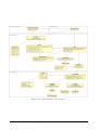
27.1 Class diagram of Glisa in increment 1 . . . . . . . . . . . . . . . . . . . . . . . . . . . 111
27.2 Class diagram of the demo application in increment 1 . . . . . . . . . . . . . . . . . . 111
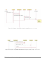
27.3 Sequence diagram that shows how an application receives events . . . . . . . . . . . . 114
27.4 Sequence diagram that shows how InputSampler performs polling on the devices . . . 114
27.5 Class diagram of increment 2. . . . . . . . . . . . . . . . . . . . . . . . . . . . . . . . . 116
27.6 Class diagram of the demo application in increment 2. . . . . . . . . . . . . . . . . . . 117
27.7 State diagram for Control class. . . . . . . . . . . . . . . . . . . . . . . . . . . . . . . 117
27.8 Class diagram of increment 3. . . . . . . . . . . . . . . . . . . . . . . . . . . . . . . . . 118
27.9 Class diagram of the demo application in increment 3. . . . . . . . . . . . . . . . . . . 118
TDT4290 Customer Driven Project, group 11
xiv
27.10State diagram for Control class in increment 3. . . . . . . . . . . . . . . . . . . . . . . 119
30.1 Transforms from physical to world space. . . . . . . . . . . . . . . . . . . . . . . . . . 134
30.2 Computation of the calibration matrix . . . . . . . . . . . . . . . . . . . . . . . . . . . 137
30.3 An application’s view of Glisa . . . . . . . . . . . . . . . . . . . . . . . . . . . . . . . . 140
31.1 The scene that is displayed when the demo application starts . . . . . . . . . . . . . . 151
31.2 The pick posture . . . . . . . . . . . . . . . . . . . . . . . . . . . . . . . . . . . . . . . 151
31.3 The selection box posture . . . . . . . . . . . . . . . . . . . . . . . . . . . . . . . . . . 152
31.4 The grab posture . . . . . . . . . . . . . . . . . . . . . . . . . . . . . . . . . . . . . . . 153
31.5 The navigation mode posture . . . . . . . . . . . . . . . . . . . . . . . . . . . . . . . . 153
31.6 Posture for entering 2D mode . . . . . . . . . . . . . . . . . . . . . . . . . . . . . . . . 154
31.7 Posture for entering 3D mode . . . . . . . . . . . . . . . . . . . . . . . . . . . . . . . . 154
31.8 Screenshot when the command ”Start Grabbing” is displayed . . . . . . . . . . . . . . 155
31.9 Screenshot when the command ”Stop Grabbing” is displayed . . . . . . . . . . . . . . . 155
31.10The posture for picking a cube . . . . . . . . . . . . . . . . . . . . . . . . . . . . . . . 156
31.11Screenshot when the eight cubes are displayed . . . . . . . . . . . . . . . . . . . . . . . 156
31.12This is the hand posture for performing a gesture. . . . . . . . . . . . . . . . . . . . . 157
31.13A screenshot of the window appearing when starting up the gesture training application.157
31.14A screenshot of the window appearing when the New Gesture button is clicked. . . . . 158
31.15A screenshot of the window appearing when the Available Gestures button is clicked. . 159
31.16A screenshot of the window appearing when the Test Gesture button is clicked . . . . 159
38.1 Tutor Finn Olav Bjrnson leads the evaluation session. . . . . . . . . . . . . . . . . . . 192
TDT4290 Customer Driven Project, group 11
xv
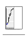
A.1 Overall project activities . . . . . . . . . . . . . . . . . . . . . . . . . . . . . . . . . . . 202
A.2 Gantt diagram showing the overall phases . . . . . . . . . . . . . . . . . . . . . . . . . 203
A.3 The planning phase . . . . . . . . . . . . . . . . . . . . . . . . . . . . . . . . . . . . . . 204
A.4 The Pre study phase . . . . . . . . . . . . . . . . . . . . . . . . . . . . . . . . . . . . . 205
A.5 The requirement specification phase . . . . . . . . . . . . . . . . . . . . . . . . . . . . 206
A.6 The construction phase . . . . . . . . . . . . . . . . . . . . . . . . . . . . . . . . . . . 207
A.7 The implementation phase . . . . . . . . . . . . . . . . . . . . . . . . . . . . . . . . . . 208
A.8 The testing phase . . . . . . . . . . . . . . . . . . . . . . . . . . . . . . . . . . . . . . . 209
A.9 The evaluation phase . . . . . . . . . . . . . . . . . . . . . . . . . . . . . . . . . . . . . 210
A.10 The presentation phase
. . . . . . . . . . . . . . . . . . . . . . . . . . . . . . . . . . . 211
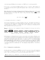
F.1 The preprocessor stage in the gesture recogniser . . . . . . . . . . . . . . . . . . . . . . 226
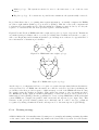
F.2 HMM with left-to-right topology . . . . . . . . . . . . . . . . . . . . . . . . . . . . . . 227
F.3 HMM with ergodic topology . . . . . . . . . . . . . . . . . . . . . . . . . . . . . . . . . 227
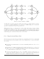
F.4 Parallel organisation of HMMs . . . . . . . . . . . . . . . . . . . . . . . . . . . . . . . 228
F.5 Markov model with three states . . . . . . . . . . . . . . . . . . . . . . . . . . . . . . . 230
F.6 Block diagram of a Vector Quantiser (inspired by the block diagram [RJ93, fig. 3.40]). 233
F.7 Flowchart of LBG (binary split) algorithm, [RJ93, fig. 3.42]. . . . . . . . . . . . . . . . 234
TDT4290 Customer Driven Project, group 11
xvi
List of Tables
4.1
Project roles
. . . . . . . . . . . . . . . . . . . . . . . . . . . . . . . . . . . . . . . . . 14
17.1 The components of VR Juggler . . . . . . . . . . . . . . . . . . . . . . . . . . . . . . . 47
17.2 List of devices supported by Gadgeteer (source: [Tea04a]) . . . . . . . . . . . . . . . . 48
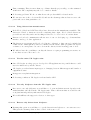
17.3 Evaluation criteria and assigned weights . . . . . . . . . . . . . . . . . . . . . . . . . . 51
17.4 Chart of how well the options meet the evaluation criteria . . . . . . . . . . . . . . . . 51
17.5 The weighted values . . . . . . . . . . . . . . . . . . . . . . . . . . . . . . . . . . . . . 53
17.6 Evaluation matrix for gesture recognition strategies . . . . . . . . . . . . . . . . . . . . 58
17.7 Evaluation criteria for the graphics package . . . . . . . . . . . . . . . . . . . . . . . . 61
17.8 The graphics model
. . . . . . . . . . . . . . . . . . . . . . . . . . . . . . . . . . . . . 62
17.9 Comparison of VTK and Open Inventor . . . . . . . . . . . . . . . . . . . . . . . . . . 63
17.10Comparison of VTK and Open Inventor . . . . . . . . . . . . . . . . . . . . . . . . . . 63
21.1 Specific requirements for support applications . . . . . . . . . . . . . . . . . . . . . . . 77
21.2 Application specific requirements . . . . . . . . . . . . . . . . . . . . . . . . . . . . . . 78
21.3 Middleware specific requirements . . . . . . . . . . . . . . . . . . . . . . . . . . . . . . 78
22.1 Performance characteristics . . . . . . . . . . . . . . . . . . . . . . . . . . . . . . . . . 96
22.2 Design constraints . . . . . . . . . . . . . . . . . . . . . . . . . . . . . . . . . . . . . . 97
TDT4290 Customer Driven Project, group 11
xvii
22.3 Software system attributes: Maintainability . . . . . . . . . . . . . . . . . . . . . . . . 97
22.4 Software system attributes: Portability . . . . . . . . . . . . . . . . . . . . . . . . . . . 97
30.1 Posture and the actions they trigger. . . . . . . . . . . . . . . . . . . . . . . . . . . . . 133
34.1 Test case 1 in the lowlevel module test . . . . . . . . . . . . . . . . . . . . . . . . . . . 172
35.1 How the requirements are tested . . . . . . . . . . . . . . . . . . . . . . . . . . . . . . 174
35.2 Test case 1 in the system test . . . . . . . . . . . . . . . . . . . . . . . . . . . . . . . . 175
35.3 Test case 2 in the system test . . . . . . . . . . . . . . . . . . . . . . . . . . . . . . . . 176
35.4 Test case 3 in the system test . . . . . . . . . . . . . . . . . . . . . . . . . . . . . . . . 177
35.5 Test case 4 in the system test . . . . . . . . . . . . . . . . . . . . . . . . . . . . . . . . 177
35.6 Test case 5 in the system test . . . . . . . . . . . . . . . . . . . . . . . . . . . . . . . . 178
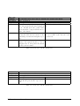
36.1 Test type . . . . . . . . . . . . . . . . . . . . . . . . . . . . . . . . . . . . . . . . . . . 179
36.2 Acceptance test . . . . . . . . . . . . . . . . . . . . . . . . . . . . . . . . . . . . . . . . 180
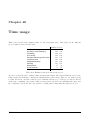
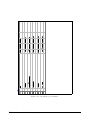
40.1 Estimated and used time in the project . . . . . . . . . . . . . . . . . . . . . . . . . . 196
K.1 Usability test for gesture training application . . . . . . . . . . . . . . . . . . . . . . . 246
K.2 Usability test for demo application . . . . . . . . . . . . . . . . . . . . . . . . . . . . . 248
Part I
Project Directive
Table of Contents
1
Introduction
5
2
Project charter
6
2.1
Project name . . . . . . . . . . . . . . . . . . . . . . . . . . . . . . . . . . . . . . . . .
6
2.2
Employer . . . . . . . . . . . . . . . . . . . . . . . . . . . . . . . . . . . . . . . . . . .
6
2.3
Stakeholders . . . . . . . . . . . . . . . . . . . . . . . . . . . . . . . . . . . . . . . . . .
6
2.4
Background . . . . . . . . . . . . . . . . . . . . . . . . . . . . . . . . . . . . . . . . . .
7
2.5
Output objectives
. . . . . . . . . . . . . . . . . . . . . . . . . . . . . . . . . . . . . .
7
2.6
Result objectives . . . . . . . . . . . . . . . . . . . . . . . . . . . . . . . . . . . . . . .
7
2.7
Purpose . . . . . . . . . . . . . . . . . . . . . . . . . . . . . . . . . . . . . . . . . . . .
7
2.8
Feasibility of the project . . . . . . . . . . . . . . . . . . . . . . . . . . . . . . . . . . .
8
2.8.1
Technological viability . . . . . . . . . . . . . . . . . . . . . . . . . . . . . . . .
8
2.8.2
Operational viability . . . . . . . . . . . . . . . . . . . . . . . . . . . . . . . . .
8
2.8.3
Commercial viability . . . . . . . . . . . . . . . . . . . . . . . . . . . . . . . . .
8
Scope of the project . . . . . . . . . . . . . . . . . . . . . . . . . . . . . . . . . . . . .
8
2.10 External conditions . . . . . . . . . . . . . . . . . . . . . . . . . . . . . . . . . . . . . .
9
2.9
2.11 Budget . . . . . . . . . . . . . . . . . . . . . . . . . . . . . . . . . . . . . . . . . . . . . 10
2.12 Deliveries . . . . . . . . . . . . . . . . . . . . . . . . . . . . . . . . . . . . . . . . . . . 10
3
Project plan
11
3.1
Success criteria . . . . . . . . . . . . . . . . . . . . . . . . . . . . . . . . . . . . . . . . 11
3.2
Risks . . . . . . . . . . . . . . . . . . . . . . . . . . . . . . . . . . . . . . . . . . . . . . 11
3.3
Work breakdown structure . . . . . . . . . . . . . . . . . . . . . . . . . . . . . . . . . . 12
3.3.1
High level project activities . . . . . . . . . . . . . . . . . . . . . . . . . . . . . 12
3.3.2
Activity relationships . . . . . . . . . . . . . . . . . . . . . . . . . . . . . . . . 12
3.3.3
Required skills . . . . . . . . . . . . . . . . . . . . . . . . . . . . . . . . . . . . 13
3.3.4
Activity schedule . . . . . . . . . . . . . . . . . . . . . . . . . . . . . . . . . . . 13
4
Organization
14
5
Templates and standards
15
5.1
Templates . . . . . . . . . . . . . . . . . . . . . . . . . . . . . . . . . . . . . . . . . . . 15
5.2
File naming and directory structure . . . . . . . . . . . . . . . . . . . . . . . . . . . . 15
5.2.1
General file naming conventions . . . . . . . . . . . . . . . . . . . . . . . . . . . 15
5.2.2
Directory structure: . . . . . . . . . . . . . . . . . . . . . . . . . . . . . . . . . 16
5.2.3
E-mails . . . . . . . . . . . . . . . . . . . . . . . . . . . . . . . . . . . . . . . . 17
6
Version control
18
7
Project follow up
19
7.1
8
Meetings . . . . . . . . . . . . . . . . . . . . . . . . . . . . . . . . . . . . . . . . . . . . 19
7.1.1
Tutor meetings . . . . . . . . . . . . . . . . . . . . . . . . . . . . . . . . . . . . 19
7.1.2
Customer meetings . . . . . . . . . . . . . . . . . . . . . . . . . . . . . . . . . . 19
7.1.3
Internal meetings . . . . . . . . . . . . . . . . . . . . . . . . . . . . . . . . . . . 19
7.2
Internal reporting . . . . . . . . . . . . . . . . . . . . . . . . . . . . . . . . . . . . . . . 20
7.3
Status reporting . . . . . . . . . . . . . . . . . . . . . . . . . . . . . . . . . . . . . . . 20
7.4
Project management . . . . . . . . . . . . . . . . . . . . . . . . . . . . . . . . . . . . . 20
Quality assurance
21
8.1
Response times with the customer . . . . . . . . . . . . . . . . . . . . . . . . . . . . . 21
8.2
Routines for producing quality from the start . . . . . . . . . . . . . . . . . . . . . . . 21
8.3
Routines for approval of phase documents . . . . . . . . . . . . . . . . . . . . . . . . . 22
8.4
Calling a meeting with the customer . . . . . . . . . . . . . . . . . . . . . . . . . . . . 22
8.5
Reports from the customer meetings . . . . . . . . . . . . . . . . . . . . . . . . . . . . 22
8.6
Calling a meeting with the tutors . . . . . . . . . . . . . . . . . . . . . . . . . . . . . . 22
8.7
Agenda for meetings with the tutors . . . . . . . . . . . . . . . . . . . . . . . . . . . . 23
8.8
Report from the last meeting with the tutors . . . . . . . . . . . . . . . . . . . . . . . 23
8.9
Routines for the distribution of information and documentation . . . . . . . . . . . . . 23
8.10 Routines for registering costs (working-hours) . . . . . . . . . . . . . . . . . . . . . . . 23
9
Test documentation
24
9.1
Module test . . . . . . . . . . . . . . . . . . . . . . . . . . . . . . . . . . . . . . . . . . 24
9.2
System test . . . . . . . . . . . . . . . . . . . . . . . . . . . . . . . . . . . . . . . . . . 25
9.3
Usability test . . . . . . . . . . . . . . . . . . . . . . . . . . . . . . . . . . . . . . . . . 25
TDT4290 Customer Driven Project, group 11
4
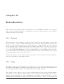
Chapter 1
Introduction
The project directive is a document whose intention is to regulate the administrative side of the
project and offer guidelines on how it is to be carried out. The document is dynamic and should
reflect administrative changes throughout the project.
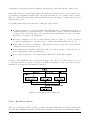
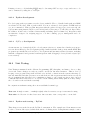
The project directive is divided into the following succeeding chapters:
Chapter 2 - The project charter, which presents the project facts.
Chapter 3 - The project plan, which presents the activities and time schedule of the project.
Chapter 4 - Organization, which contains information regarding the team structure.
Chapter 5 - Templates and standards, which provides project standards that will ensure document consistency.
Chapter 6 - Version control, which introduces the software used for version control of the
project.
Chapter 7 - Project follow up, which documents the proposed procedures to maintain project
progress.
Chapter 8 - Quality Assurance, which aims to document procedures to ensure project quality.
Chapter 9 - Test documentation, which describes the testing routines for the project.
TDT4290 Customer Driven Project, group 11
5
Chapter 2
Project charter
The project charter is an agreement between the customer and the project group that summarizes
the concepts of the project.
2.1
Project name
The name of the project is Glove is in the Air, as is the name of the end product. The short version
of the name, to use when referring to the product, is Glisa.
2.2
Employer
Bjørn K. Alsberg at the Institute of Chemistry, NTNU.
2.3
Stakeholders
The following were identified to be the main stakeholders of the project:
Project group
Customer
Tutors
The full list of names with contact details can be found in Appendix C.
TDT4290 Customer Driven Project, group 11
6
2.4
Background
This project is carried out as a part of the course TDT4290 Customer Driven Project, which forms
a part of the Master of Computer Science Program at NTNU. The objectives of this course are
to enhance student’s practical knowledge by carrying out all phases of a real project for a given
customer. The students participating in this course were randomly divided into groups and given
random projects.
The customer in our particular project is the Chemometrics Group at the Institute of Chemistry
at NTNU. They have caught interest in the use of virtual reality (VR) as a tool for inspecting
complicated data. In accordance with the objectives they have given us, we are determined to
develop and document a communication interface between a demo application and the virtual reality
gloves. Depending on the quality of the product they intend to use this for future integration with
their existing SciCraft data analyzing tool (www.scicraft.org), where they wish to use the virtual
gloves to control objects.
2.5
Output objectives
The overall objective of the project is to develop a library that can be used by the SciCraft software
as an interface to the virtual gloves somewhere in the future. This will lead to the possibility of using
virtual gloves as a more intuitive and user-friendly approach to manipulating data. This is especially
meant to ease the handling and understanding of complex 3D-rendered molecules and to achieve a
closer interaction between analysis and visualization.
2.6
Result objectives
The overall purpose of the project should be realized through the following result oriented goals:
Develop low-level drivers to the data gloves and Flock of Birds.
Develop a middleware library that allows the gloves to interact with 3D-objects in a VR environment.
Develop a demonstration program that shows the functionality of the library.
2.7
Purpose
The Chemometrics group uses a VR laboratory to visualize statistical plots and molecule structures
in three dimensions using passive stereo. Since this technology requires light from the projectors to
pass through polarisation filters, the lights in the lab will typically be dimmed to make the projected
TDT4290 Customer Driven Project, group 11
7
image appear clearer, thus making keyboard interaction with the computer less feasible. Moreover,
keyboard interaction is not very intuitive and requires extensive training to be efficient.
It is the purpose of this project to create a library for communication with virtual gloves allowing
intuitive rotation and manipulation of three dimensional data. This data mainpulation will be realised
through hand gestures and postures from data glove input devices, which will replace textual and
mouse input.
2.8
Feasibility of the project
There are several reasons to why this project is interesting and feasible both technologically, operationally and commercially.
2.8.1
Technological viability
Since no non-commercial software of this kind is known, a software development project is required
for making SciCraft VR-enabled. The lower level software which connects to hardware devices is to
be written in C++. This is a language that is well established and for which compilers exist for most
platforms, in case a later project is established to port the software to a different platform. The rest
of the library shall be developed in Python, which represents a higher level of abstraction and thus
hopefully less and more readable code.
2.8.2
Operational viability
Using data gloves to manipulate data is much more intuitive than using a keyboard, and presumably
more efficient as well, since humans from birth are trained to use their hands to manipulate their
surroundings. The time required for training will also be less than if complex mouse- and keyboard
commands are to be learned.
2.8.3
Commercial viability
The project is required to release all sources under GPL, so the program cannot be sold commercially.
However, Institute of Chemistry may get an advantage from being technologically ahead of other
institutions when competing for the best students and researchers.
2.9
Scope of the project
The scope of the project is defined by the bullet points stated above in section 2.6. A detailed
description of the work breakdown structure (WBS) is documented in section 3.3.1. The overall
TDT4290 Customer Driven Project, group 11
8
phases are as follows:
Planning
Prestudy
Requirements specification
Construction
Implementation
Testing
Evaluation
Presentation
These phases are further broken down into appropriate tasks that are carried out in order to reach
the overall goals. Each phase is documented and the documents are to be approved by the customer.
Concrete deliveries, in addition to the phase documents, which define the scope of the project are:
Source code for the library.
API-documentation for the library.
Design documentation.
Source code for the demonstration application.
Phase documents and final project report.
Oral presentation and practical demonstration of the project results.
2.10
External conditions
The following conditions are predetermined and must be considered throughout the project:
SubVersion should be used as version control system.
The system must run on Debian Unstable.
The demonstration program should use Visualization Toolkit (VTK) and Qt/PyQT.
C++ and/or Python should be used as developing tools.
All low-level drivers should be independent of VTK.
Documentation is required and must be written in English and in LATEX format.
All code should be open source GNU Public Licensed (GPL)
TDT4290 Customer Driven Project, group 11
9
2.11
Budget
Each project member is estimated to work 24 hours per week in 12 weeks and 3 days, which approximately results in 305 hours on the project. The total number of hours estimated for the project will
then be 1830. As this project is carried out as part of the course TDT4290 Customer Driven Project,
no salaries or money are involved.
2.12
Deliveries
Important dates for the project:
August 24th, 2004: Project start.
October 28th, 2004: Pre delivery of pre study report and requirement specification.
November 18th, 2004: Presentation and delivery of final report.
TDT4290 Customer Driven Project, group 11
10
Chapter 3
Project plan
This section will provide an overview of the phase activities and milestones of the project along with
the work breakdown structure.
3.1
Success criteria
These defined success criteria will be used during the project evaluation to determine the project
success:
The low-level communication library is implemented, tested and found functionally complete
with respect to the features of the hardware.
The middleware providing higher-level functions responds to simple hand gestures and reports
picking and movement events.
The demo application clearly presents the system functionality.
3.2
Risks
These risks were immediately identified during the project planning:
The middleware recognising gestures constitutes a technology risk, as the project’s success is
dependent on that the construction/adaption of suitable algorithms is successful.
Given the exploratory nature of the project, it is vital that the gathering of requirements
from the customer is done thoroughly. However, even when sufficient attention is directed at
getting the requirements correct during the requirement gathering phase, the customer may
later change his mind, introducing delays and new difficulties into the project – in the worst
case rendering the entire design obsolete.
TDT4290 Customer Driven Project, group 11
11
The projects’ factors of risk are further elaborated in appendix D
3.3
Work breakdown structure
This section will clarify the work breakdown structure of the entire project.
3.3.1
High level project activities
The project has been divided into eight main phases, where the estimated percentage of total project
time is given in the brackets:
Planning (11%)
Pre study (19%)
Requirement specification (12%)
Construction (12%)
Implementation (20%)
Testing (8%)
Evaluation (2%)
Presentation (3%)
This makes up 87 % of the total project time, whereas the rest of the time is estimated for project
management, lectures and self study. A more detailed overview of the project activities is provided
in appendix A.
3.3.2
Activity relationships
The relationships between the activities can be read from the Gantt-diagram in appendix A. They
are intended to be carried out in a quite sequential manner, with some overlap, meaning that some
resources could be allocated to a subsequent phase while others complete the preceding phase. Between the construction and implementation phase, this kind of overlap would lead to an incremental
development. Some testing will be carried out during the requirement specification and implementation phases, while a full system test and usability confirmation test will be done during the testing
phase. The project evaluation and presentation will be standalone phases at the end of the project
and will be done after completion of the final report.
TDT4290 Customer Driven Project, group 11
12
3.3.3
Required skills
The skills the group members are required to possess to complete this project are:
The project coordinator must have skills in project management, in addition to the technical
demands of the project.
The delivered library is required to be written i C++ and Python, and it is necessary that the
group’s members know or learn this language.
All documentation is to be written with the LATEX type-setting system, and knowledge of how
to document using LATEX is therefore a requirement to all group members.
3.3.4
Activity schedule
See figures A.1 to A.10 in appendix A for project activities and Gantt diagrams of the different
phases.
TDT4290 Customer Driven Project, group 11
13
Chapter 4
Organization
This chapter will provide a brief overview of the group structure within the project team.
Each member of the project team has been assigned one or more roles that defines their main area of
responsibility. Although a project leader has been assigned under the role name project coordinator,
the authority hierarchy in the group is rather flat. This is meant in the sense that the project
coordinator is responsible for the project progress, but the process of decision making is carried out
in democracy.
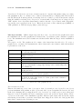
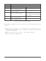
The main roles of the project along with the group members responsible for each one of them are
stated in table 4.1.
Project coordinator Erik
Makes sure the project follows the planned progression
Document keeper Trond
Responsible for gathering, organizing and filing of all documents
Lead Programmer Stein Jakob Must keep a system in all source code, and ensure that all code
conventions are carried out
Design
Øyvind
Must ensure that the overall design of the project meets the requirements stated in the requirements specification
Quality assurance Lars-Erik
Will create and follow up on routines that should guarantee the
quality of the end product
Customer contact Frode
Sustain communication with the customer
Timekeeper
Øyvind
Will keep track of the time schedule for all group members and
compare estimated time with actual time spent
Tester
Frode
In charge of testing throughout the project
Table 4.1: Project roles
TDT4290 Customer Driven Project, group 11
14
Chapter 5
Templates and standards
The following templates and standards are to be used to ensure consistency for all documents throughout the project.
5.1
Templates
Templates for summons, minutes and status report are established in order to standardize these
documents, which are reproduced every week. The templates can be found in appendix B. As for
phase documents, this project directive will serve as the template.
5.2
File naming and directory structure
This section provides file naming conventions and directory structure for the project documentation.
5.2.1
General file naming conventions
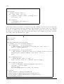
File names must not contain blank spaces and must be named with the correct file type suffix which
is described in section 5.2.1.1 - 5.2.1.3.
5.2.1.1
Internal documents:
This naming convention should be applied to documents for minutes, status reports and summons,
respectively:
TDT4290 Customer Driven Project, group 11
15
minutes category of meeting yymmdd
statusreport yymmdd
summons yymmdd
5.2.1.2
Project directive:
The main document will be project directive, the parts of the document will be stored in files named
as follows:
charter, project plan, organisation, templates, version control, project follow up, quality assurance,
test plan.
5.2.1.3
Phase documents:
The phase documents will be named as follows:
project directive,
prestudy,
requirements specification,
test documentation, evaluation, presentation.
5.2.2
construction,
implementation,
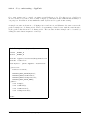
Directory structure:
documentation/: All the documentation in our project, that is everything but source code and
executable files
source/: Source code and executable files
documentation/internal/: All internal documentation, not included in the report
documentation/report/: The report, that is the final, textual deliverable
documentation/internal/minutes/: Minutes from meetings, in .tex format
documentation/internal/status/: Weekly status reports, in .tex format
documentation/internal/summons/: Summons for meetings, in .tex format
documentation/templates/: Stand-alone templates for status reports, minutes and summons, as
opposed to those that are included in the project directive
source/doc/: The API documentation for specific source files
source/lib/: Drivers and libraries
source/bin/: Executable, binary files
source/src/: Source code files
documentation/report/ will be divided into sub directories according to the chapters of the project
report. The chapters will consist of the project directive, the phases and more, to be defined.
The project directive directory will also be divided into directory for each of its components.
TDT4290 Customer Driven Project, group 11
16
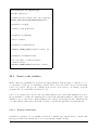
5.2.3
E-mails
When files are sent to the tutors the extension kpro11 is added to the file names to ease their process
of keeping track of files from different groups. All e-mails sent to the tutors and the customer should
also include the [kpro11] prefix in the subject field.
TDT4290 Customer Driven Project, group 11
17
Chapter 6
Version control
In accordance with given customer demands, SubVersion is used for version control of code. We have
no experience with other version control systems, and prefer to stick with one standard. Therefore
SubVersion is also used for version control of documents.
We have a SubVersion repository configured at one of the group members home directory at
vier.idi.ntnu.no. Further file and directory structure of the repository is explained under directory
structure in section 5.2.2.
In addition all phase documents are to be marked with the version number and date in order to
ensure version-correctness for external readers.
All documentation files are stored in SubVersion as .tex files as changes are frequently made and
can be directly edited into the .tex files. All internal documents, completed phase documents and
individual parts in phase documents are also compiled into .pdf format and communicated through
It‘s learning, in appropriate folders.
TDT4290 Customer Driven Project, group 11
18
Chapter 7
Project follow up
The sections of this chapter are to ensure the follow up and progress of the project.
7.1
Meetings
We have scheduled weekly meetings on Mondays for the group internally and with our tutors. Customer meetings are also scheduled on Mondays, when needed. See templates for summons in appendix B.
7.1.1
Tutor meetings
We have scheduled weekly meetings with our tutors 1015-1100 on Mondays in room IT458. The
weekly status report is discussed and approved, along with the previous minute, current phase documents, and other questions about the project process that has occurred.
7.1.2
Customer meetings
We have meetings with the customer when we need to discuss or clarify certain questions. These
meetings will primarily be held on Mondays from 1115-1200 at the Institute of Chemistry.
7.1.3
Internal meetings
We have internal meetings every Monday to discuss the status, plan the upcoming activities, divide
tasks etc. The meeting is from 1115-1200 if we do not have a customer meeting, otherwise from
1215-1300 in room IT458. We write minutes and use an agenda for our internal meetings as well as
the ”external” ones in order to document what has been decided and keep an acceptable efficiency.
TDT4290 Customer Driven Project, group 11
19
7.2
Internal reporting
We report the status on weekly hours along with the degree of completion of activities and weekly
milestones. The status will be discussed on the weekly internal meetings. The hours used from
Thursday 00:00 to Thursday 00:00 must be reported to the timekeeper before 00:00 every Thursday.
7.3
Status reporting
We report a written weekly status to our tutors and customer that is sent along with the summons.
See the templates in appendix B.
7.4
Project management
We are using the TROKK model of project management and discuss it in every tutor meeting as a
part of the status report, see Appendix B. TROKK are the capital letters of the model’s constituents,
in Norwegian. We use the term TROKK here since we will use this model in Norwegian, although
we describe it in English in this document.
Time(no:Tid): Are we in schedule according to planned milestones and activities?
Risk(no:Risiko): What are the risks that threaten the project? What is the likelihood and
consequences of them striking, and what will be done if a risk strikes? Who’s in charge of
handling the specific risks? See the risk table in appendix D.
Scope(no:Omfang): How much are we able to produce? Will we have to leave out or add some
functionality, due to lack of time or changes in the customer requirements?
Cost(no:Kostnad): In our project, cost will be used in the sense of working-hours, since no
money is flowing in our project. Is the group efficient? Estimated versus spent time? This
would really be important in a real working situation, where the workers are actually paid for
the hours they spend on the project and fines are often agreed upon if the project team fail to
deliver on time.
Quality(no:Kvalitet): Will we have to reduce the product’s quality for some reason?
TDT4290 Customer Driven Project, group 11
20
Chapter 8
Quality assurance
This chapters aims for ensuring the quality of both the end product and the administration of the
project. Routines are described for various tasks and more will be added continuously as they are
needed.
8.1
Response times with the customer
The following response times were agreed upon with the customer:
Approval of minutes from the last customer meeting: Within 48 hours after minutes is sent to
the customer.
Feedback on phase documents sent to the user for review: On the coming customer meeting.
Approval of phase documents: Within 48 hours.
Answering questions: Within 48 hours.
Put forward documents: Reply within 48 hours and forward documents when located.
8.2
Routines for producing quality from the start
In orders to stress the importance of producing quality from the start, the following routines are
worked out:
Close cooperation with the customer
Strict report writing to ensure correct requirements
All group members are responsible for the quality of their own work and accountable for possible
errors
TDT4290 Customer Driven Project, group 11
21
8.3
Routines for approval of phase documents
1. The group gathers to review the documents internally and a copy is simultaneously reviewed
by the tutors.
2. After the internal approval and feedback from the tutors the phase documents are sent to the
customer by e-mail
3. The customer approves the documents, possibly gives feedback within agreed response time
4. The group revises the phase documents
5. Back to pt.1
8.4
Calling a meeting with the customer
1. Proposal for summons is to be sent by e-mail to all group members within 48 hours before it is
to be sent to the customer
2. All group members should respond within 18 hours to present their views
3. Possible changes are made, and the final summons is sent to the group member responsible for
customer relations
4. The group member responsible for customer relations sends the summons to the customer,
tutor assistant and all group members by e-mail at latest at 12:00 the day before the meeting
8.5
Reports from the customer meetings
1. Proposal for report is to be sent by e-mail to all group members within 12:00 the day after the
meeting
2. All group members should respond within 12 hours to present their views
3. Possible changes are made, and the final report is sent to the group member responsible for
customer relations
4. The group member responsible for customer relations sends the report to the customer and all
group members by e-mail at latest at 16:00 two days after the meeting took place
8.6
Calling a meeting with the tutors
1. Proposal for summons is to be sent by e-mail to all group members before 12:00 the day before
it is to be sent to the tutors
2. All group members should respond within 12 hours to present their views
3. Possible changes are made, and the final summons is sent to the tutors and all group members
by e-mail at latest 12:00 the day before the meeting
TDT4290 Customer Driven Project, group 11
22
8.7
Agenda for meetings with the tutors
1. Approval of the agenda
2. Approval of report from the last meeting with the tutors
3. Comments on report from the last meeting with the customer
4. Approval of status report
5. Walkthrough/Approval of enclosed phase documents
6. Other topics
8.8
Report from the last meeting with the tutors
1. Proposal for report is to be sent by e-mail to all group members within 12:00 the day after the
meeting
2. All group members should respond within 12 hours to present their views
3. Possible changes are made, and the final report is enclosed with the summons for the next
meeting
8.9
Routines for the distribution of information and documentation
A web-page is to be published at ’It’s:learning’. All information/documentation is to be referred
to from this page. If the information/documentation is available on the Internet, a hyperlink is to
be placed at the published web-side together with a brief summary of its contents. If the information/documentation is only available in a non-electronic form, the web-page should refer to were the
information/documentation is physically placed.
8.10
Routines for registering costs (working-hours)
Every week all group members are to report their working hours for the previous week. A working
week ranges from Thursday 00:00 to Thursday 00:00 the following week. The report should be
delivered to the group member responsible for registering working hours. Which task is worked on
and the current overall phase are also to be registered along with the working hours. The report
should be delivered as a spreadsheet that is open office compatible.
TDT4290 Customer Driven Project, group 11
23
Chapter 9
Test documentation
This section describes the testing routines the project will use, and when the different tests will be
carried out.
9.1
Module test
Goal
The goal of this test is to eliminate all errors in the individual modules of the system.
How to test
A test plan should be written for the testing of each module and they should mainly focus on testing
whether or not the different modules meet the requirements stated in the requirements specification.
When
Since the different modules will be defined in the construction phase of the project, a test plan for
each module should also be in made in the construction phase. The test itself should be executed in
the implementation phase immediately after the completion of each module.
Responsibilities
Test plans: Stein Jakob
Execution: The implementors of each module
TDT4290 Customer Driven Project, group 11
24
Evaluation: Frode
9.2
System test
Goal
The idea of the system test is to check if all the modules work together to produce the expected
results.
How to test
In this test the complete product should be tested. It is supposed to find errors in the integration of
the individual modules, so errors in the modules it selves should not occur in this test phase. Again
the test result should be compared to the requirements specification to determine if the system meets
the expected results.
When
A test plan can be written concurrent with the development of the requirements specification. It
should ensure that all requirements are tested.
Responsibilities
Test plans: Frode
Execution: Entire group
Evaluation: Øyvind and Frode
9.3
Usability test
Goal
The test should show if the finished system is working in an intuitive way for the end user.
TDT4290 Customer Driven Project, group 11
25
How to test
The entire system with the demo application should be used in this test. Most programming errors
should already have been eliminated in the module tests and the system test. Standard usability
testing techniques should be used, with several test persons who are not already familiar with the
system.
When
The test plan should be developed together with the requirements specification and executed in the
testing phase after the system test.
Responsibilities
Test plans: Frode
Execution: Entire group
Evaluation: Erik and Trond
TDT4290 Customer Driven Project, group 11
26
Part II
Prestudy
TDT4290 Customer Driven Project, group 11
28
Table of Contents
10 Introduction
31
11 Description of the customer
33
11.1 NTNU . . . . . . . . . . . . . . . . . . . . . . . . . . . . . . . . . . . . . . . . . . . . . 33
11.2 The Chemometrics and Bioinformatics Group . . . . . . . . . . . . . . . . . . . . . . . 34
12 Glove is in the air - what is it?
35
13 Operational requirements
36
14 Evaluation criteria
37
14.1 Evaluation criteria for low level drivers . . . . . . . . . . . . . . . . . . . . . . . . . . . 38
14.2 Evaluation criteria for the middleware level . . . . . . . . . . . . . . . . . . . . . . . . 38
14.3 Evaluation criteria for application level (graphics package) . . . . . . . . . . . . . . . . 38
15 Theory
39
15.1 Virtual reality . . . . . . . . . . . . . . . . . . . . . . . . . . . . . . . . . . . . . . . . . 39
15.2 Display devices . . . . . . . . . . . . . . . . . . . . . . . . . . . . . . . . . . . . . . . . 39
15.3 Human computer interface devices . . . . . . . . . . . . . . . . . . . . . . . . . . . . . 40
16 Description of the existing system
41
16.1 SciCraft . . . . . . . . . . . . . . . . . . . . . . . . . . . . . . . . . . . . . . . . . . . . 41
16.2 5DT Data Glove 5 . . . . . . . . . . . . . . . . . . . . . . . . . . . . . . . . . . . . . . 42
16.2.1 Introduction . . . . . . . . . . . . . . . . . . . . . . . . . . . . . . . . . . . . . 42
16.2.2 Gestures and mouse emulation . . . . . . . . . . . . . . . . . . . . . . . . . . . 42
16.2.3 Driver . . . . . . . . . . . . . . . . . . . . . . . . . . . . . . . . . . . . . . . . . 43
16.2.4 Usability of driver . . . . . . . . . . . . . . . . . . . . . . . . . . . . . . . . . . 43
16.3 Flock of Birds . . . . . . . . . . . . . . . . . . . . . . . . . . . . . . . . . . . . . . . . . 43
16.3.1 How it works . . . . . . . . . . . . . . . . . . . . . . . . . . . . . . . . . . . . . 43
16.3.2 Controlling the birds . . . . . . . . . . . . . . . . . . . . . . . . . . . . . . . . . 44
16.3.3 The existing system . . . . . . . . . . . . . . . . . . . . . . . . . . . . . . . . . 44
16.3.4 The desired system . . . . . . . . . . . . . . . . . . . . . . . . . . . . . . . . . . 44
16.4 Hololib . . . . . . . . . . . . . . . . . . . . . . . . . . . . . . . . . . . . . . . . . . . . . 45
16.4.1 The mockup VR-glove . . . . . . . . . . . . . . . . . . . . . . . . . . . . . . . . 45
16.4.2 Functionality . . . . . . . . . . . . . . . . . . . . . . . . . . . . . . . . . . . . . 45
17 Alternative solutions
46
17.1 Low level drivers . . . . . . . . . . . . . . . . . . . . . . . . . . . . . . . . . . . . . . . 46
17.1.1 Description of low level drivers . . . . . . . . . . . . . . . . . . . . . . . . . . . 46
17.1.2 Evaluation of solutions for low level drivers . . . . . . . . . . . . . . . . . . . . 49
17.2 The middleware . . . . . . . . . . . . . . . . . . . . . . . . . . . . . . . . . . . . . . . . 53
17.2.1 Introduction . . . . . . . . . . . . . . . . . . . . . . . . . . . . . . . . . . . . . 53
17.2.2 Evaluation criteria . . . . . . . . . . . . . . . . . . . . . . . . . . . . . . . . . . 54
17.2.3 Description of the different approaches . . . . . . . . . . . . . . . . . . . . . . . 56
17.2.4 Evaluation of the different approaches . . . . . . . . . . . . . . . . . . . . . . . 58
17.2.5 External library: Torch . . . . . . . . . . . . . . . . . . . . . . . . . . . . . . . 59
17.3 The application layer . . . . . . . . . . . . . . . . . . . . . . . . . . . . . . . . . . . . . 60
17.3.1 Introduction . . . . . . . . . . . . . . . . . . . . . . . . . . . . . . . . . . . . . 60
17.3.2 Evaluation criteria . . . . . . . . . . . . . . . . . . . . . . . . . . . . . . . . . . 60
17.3.3 Description of alternative solutions . . . . . . . . . . . . . . . . . . . . . . . . . 61
17.3.4 Evaluation of the different alternatives . . . . . . . . . . . . . . . . . . . . . . . 63
17.4 Programming languages . . . . . . . . . . . . . . . . . . . . . . . . . . . . . . . . . . . 64
17.4.1 C++ . . . . . . . . . . . . . . . . . . . . . . . . . . . . . . . . . . . . . . . . . . 64
17.4.2 Python . . . . . . . . . . . . . . . . . . . . . . . . . . . . . . . . . . . . . . . . 65
17.4.3 Comparison . . . . . . . . . . . . . . . . . . . . . . . . . . . . . . . . . . . . . . 65
18 Conclusion
66
18.1 Low level drivers . . . . . . . . . . . . . . . . . . . . . . . . . . . . . . . . . . . . . . . 66
18.2 Middleware solutions . . . . . . . . . . . . . . . . . . . . . . . . . . . . . . . . . . . . . 66
18.3 Application layer solution . . . . . . . . . . . . . . . . . . . . . . . . . . . . . . . . . . 67
TDT4290 Customer Driven Project, group 11
30
Chapter 10
Introduction
This is the prestudy document of group 11 in the course TDT4290 Customer driven project. The
group is carrying out a project for the Chemometrics Group at the Institute of Chemistry at NTNU.
The project is established with the objective of developing a library with which to connect virtual
reality gloves with their existing data analyzing tool SciCraft.
The purpose of this phase is to extend our knowledge regarding existing technology and business
processes within the customer environment, and explore compatible technologies in the market that
we can make efficient use of in order to address the requirements given. Potential solutions will be
sketched based on this knowledge and assessed against given evaluation criteria. This evaluation will
assist us in reaching a final conclusion on the most suitable solutions for the project.
Some of the topics described in this document have a very technical nature and some parts may be
affected by technical language and terms. We are however confident that the document is written in
a form understandable for our customer, who are familiar with most of these expressions.
The prestudy document is divided into the following succeeding chapters:
Chapter 11 - Description of the customer, which provides a brief overview of the customer and
their position in the organization.
Chapter 12 - Glove is in the air - what is it?, which provides a description the project.
Chapter 13 - Operational requirements, which states the operational requirements set for the
project.
Chapter 14 - Evaluation criteria, which provides criteria of which to evaluate different solutions
against.
Chapter 15 - Theory, which introduces the area of technology we will operate in during the
project.
Chapter 16 - Description of existing system, which describes SciCraft and the devices we intend
to use in the project.
Chapter 17 - Alternative solutions, which describes the different solutions we have looked at
along with an evaluation of them. Development tools are also evaluated in this chapter.
TDT4290 Customer Driven Project, group 11
31
Chapter 18 - Conclusion, which presents the different choices of solutions.
TDT4290 Customer Driven Project, group 11
32
Chapter 11
Description of the customer
The project Glove is in the Air (Glisa) is assigned from the Chemometrics and Bioinformatics Group
(CBG) at the Institute of Chemistry at Norwegian University of Technology and Science (NTNU) in
Trondheim, and the customer contact person is Bjørn K. Alsberg.
The following sections will provide a brief overview over the whole organization of Norwegian University of Technology and Science (NTNU) and a small group called the Chemometrics and Bioinformatics Group under the Institute of Chemistry.
11.1
NTNU
NTNU was established January 1st, 1996 by a restructuring and renaming of the University of
Trondheim (UNiT) and The Norwegian University of Technology (NTH). Today approximately 20000
students are enrolled at NTNU and half of them are undertaking technical degrees. The whole
organization of NTNU has an annual budget of 2.8 billion kr.
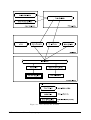
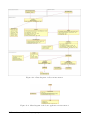
Figure 11.1: Organization chart of NTNU [Dah04]
TDT4290 Customer Driven Project, group 11
33
NTNU is controlled through a board and the headmaster is the leader of the board. The organization
is further divided into seven faculties and 53 institutes as shown in figure 11.1 above, where the
Institute of Chemistry is incorporated under the Faculty of Natural Science and Technology.
The next section will describe the actual customer, which is a part of the NTNU organization.
11.2
The Chemometrics and Bioinformatics Group
As stated above, CBG is located under the Institute of Chemistry at the Faculty of Natural Science
and Technology. CBG is a part of FUGE bioinformatics platform branch in Trondheim, which is one
of the big programs of the Norwegian research council, within functional gene research.
The primary focus of CBG is to develop new data analytical methods within the fields of chemometrics
and bioinformatics. Within chemometrics they are, according to [CG04] particularly interested in:
Efficient representations of spectra
Hyperspectral image analysis
Quantitative structure-activity relationships
Drug design
Within bioinformatics they focus on:
Simulation of microarrays
Methods for gene selection
Gene ontology as background information
Finding comparable protein spots in gels
Whole cell fingerprinting
Additionally CBG provides free data analysis through their NTNU Data Analysis Centre (NDC) and
an open source data analysis software called SciCraft is under development.
TDT4290 Customer Driven Project, group 11
34
Chapter 12
Glove is in the air - what is it?
As mentioned in the previous chapter this project is carried out as a part of the course TDT4290
Customer Driven Project, which is integrated in the Master of Computer Science program with the
Chemometrics and Bioinformatics Group (CBG) as our customer.
The customer is mainly focused around data analysis methods, and the data analysis tool SciCraft is
already under development. As of today, this system is mainly based on 2D graphics with keyboard
and mouse as the key input devices. The intention of this project is to introduce virtual reality(VR)
gloves into data analysis software by creating low level communication between the system and the
VR gloves, and integrate the gloves with the existing software to some extent. Handling 3D data
through the use of virtual gloves is more intuitive than through textual and menu based commands,
and if gestures are implemented in a correct manner they can serve as basis for very user friendly
and powerful data analysis. Another obvious advantage of enabling gestures handling is that these
3D operations are carried out in a VR lab, with lights turned off and 3D glasses put on. Handling
the keyboard in such a setting is challenging. A future integration with SciCraft will also improve
the data analysis as increasing visualization implies increasing insight.
Although we have a common understanding with the customer that the main priority is to get the
5DT Data Glove 5 (see section 16.2) to function properly, we want to make this as compatible as
possible with the existing SciCraft data analysing tool. The low level communication and integration
with Flock of Birds (see section 16.3) will form the basis, but beyond that we want to develop a
well defined middleware that supports gestures. Additionally we will develop an illustrative demo
application showing the possibilities within the area of data gloves and virtual reality.
TDT4290 Customer Driven Project, group 11
35
Chapter 13
Operational requirements
These chapter provides operational requirements, which is an overall description of what functionality
our product will offer. These requirements can be seen as an elaboration of the result objectives stated
in the project charter. Below follows the list of operational requirements, which will further be broken
down into functional and non-functional requirements in the requirement specification phase.
Operational requirements:
1. Make support for low level communication between the existing system and virtual reality
gloves. All low level drivers should be independent of any graphics library.
2. Make instructions from the user to the computer keyboard-independent.
3. Develop a middleware library that allows the virtual reality gloves to interact with 3D-objects
in a VR environment.
4. Make a demo application showing the virtual gloves’ functionality.
5. Enable SciCraft developers to integrate this 3D virtual reality into SciCraft.
It is common practice in system engineering projects to determine the business requirements as well
as the operational requirements. However, Glisa is not a traditional system engineering project in
the sense of developing an application to enhance the business processes of the customer. The result
of this project is supposed to be integrated into SciCraft by CBG and the end result of that process
will hopefully benefit the business processes of those making use of the end system. As business
requirements relates to the work routines surrounding the software system, in our case, SciCraft
is not widely in use yet, and few routines are defined for the system. Our focus in this project is
therefore future integration with SciCraft rather than determining the business processes of future
end users of the system.
TDT4290 Customer Driven Project, group 11
36
Chapter 14
Evaluation criteria
During the prestudy phase we have looked at different solutions of which to approach the project.
Some of them were discarded during the preliminary sorting, but the most interesting solutions had
to be assessed against given evaluation criteria to distinguish them and conclude the most optimal
solution. This chapter will present these evaluation criteria.
Glove is in the Air (Glisa) will be a system that operates at different levels. From the nature of the
project we can argue that the end product should be divided into three layers:
Firstly, in Glove is in the Air (Glisa) we are concerned with issues ranging from reading signals from
Human Computer Interaction (HCI) devices through a serial port, to interpreting these signals, to
visualization in 3D.
Secondly, there is an essential requirement of modularity, since our product will be integrated in the
SciCraft tool for interactive data analysis and will be further developed by the SciCraft team. The
hardware support of the HCI devices and the interpretation of the hardware input signals is what
will be integrated into SciCraft. In addition, we are required to produce a demo application that
shows what our module is capable of.
Naturally, we will need a clear cut interface between the demo application and the rest, so that the
developers taking over our product will not have to pry it apart. Clearly separating the reading of
hardware signals and the interpretation of them, is believed to ease the development process, both
for ourselves and for the SciCraft team.
Although the layers of Glisa will not be completely defined before the construction phase, we can
from these conditions already separate layers that the end product must consist of:
Low level drivers: This layer will do all communication with the HCI devices used.
Middleware layer: This part of the system will probably do all gesture recognition and also
allow devices to be used in 3D applications.
Application with 3D visualization: This layer will use the middleware to control a 3D environment.
It is clear that each layer needs different solutions, and the requirements for the solutions varies with
the layers. We will now define the evaluation criteria used to assess the different solutions of the
different layers in chapter 17.
TDT4290 Customer Driven Project, group 11
37
14.1
Evaluation criteria for low level drivers
The solutions for low level drivers are assessed against the following evaluation criteria:
How difficult it will be to implement the solution in our system.
The amount of work required to learn how the solution functions.
How compatible the solution is with the GNU General Public License (GPL).
The estimated overall quality of the solution.
How dependent our project will be on 3rd parties by using the solution.
How accessible the source code of the solution is.
14.2
Evaluation criteria for the middleware level
The solutions for the middleware level are assessed against the following evaluation criteria:
How new gestures are introduced to the system.
The computational complexity of the system.
The recognition rate of the system.
Whether the system is able to successfully recognise gestures performed continuously.
Flexibility concerning finger positions and movements in the recognition process.
These criteria are further elaborated in section 17.2.2.
14.3
Evaluation criteria for application level (graphics package)
The solution for the graphics package in the application layer is assessed against the following evalution criteria:
Does the package have a Python binding?
Is the package already in use in SciCraft (VTK)?
Is the package on a high conceptual level?
Does the package have a good estimated overall quality?
These criteria are explained in section 17.3.2.
TDT4290 Customer Driven Project, group 11
38
Chapter 15
Theory
This chapter provides a brief description of virtual reality, 3D display devices and Human Computer
Interaction (HCI) devices. Understanding these terms is essential for our particular project and they
are therefore explained in some detail. This is useful background information for the succeeding
chapters, which describes technical matters and concrete systems concerned with these terms.
15.1
Virtual reality
As computers have evolved, simple number crunching is not the only application available. Visualization is one of the areas of use that has become an enormous aid for scientists, making interpretation
of large amounts of data intuitive and easy. One of the most recent applications of visualization, is
virtual reality(VR). Unlike other computer visualization, virtual reality tries to make an illusion of
being inside a scene, and not only an outside spectator. Users can interact with objects, and get
immediate response. Virtual reality has also found its way to the entertainment industry, as many
games today gives a first person perspective of 3D scenes.
15.2
Display devices
There exists numerous different VR display systems. The most basic one, is an ordinary computer
2D-display, which provides no real 3D view, but can emulate 3D with use of perspective projection.
Since every desktop computer has a display, a wide range of applications supports simple virtual
reality on 2D displays. There also exists advanced special built VR systems which use ordinary 2D
displays for projection with good result. The good results are an effect of the human interpretation
of visual impressions. When the objects are far away, the human eye only sees a 2D image, since
triangulation is not possible. The distance to objects, are then determined by empiri and perspective,
so regular 2D displays works just as good as 3D displays. Typical special built VR systems using 2D
displays are simulators, such as flight simulators, naval simulators and car simulators.
Many of the more advanced VR applications use real 3D projection. There are many different
systems, but they all use the technique of stereo vision, where each eye gets presented a slightly
TDT4290 Customer Driven Project, group 11
39
different image. In this way, it is possible to emulate the natural triangulation humans do on objects
close to the eyes(typically < 5m). There are numerous different implementation of stereo vision
virtual reality solutions. From head displays, to large installations where images are projected on
the walls and on the floor.
One easy way of obtaining stereo vision is by using two projectors with polarization filters, so that
a viewer can experience stereo vision by wearing polarization glasses. It is called passive stereo, and
exploit the fact that light waves are waves with different polarization. By adding different polarization
filters in front of the projector, it is possible to see the light emitted from one projector when you use
a corresponding polarization filter in front of an eye. A drawback of polarization, is that the light
intensity degrades, since a polarization filter only let parts of the total amount of light trough.
Another way of experience stereo vision, is by a method called active stereo. In active stereo projections, only one projector is needed, but the glasses is far more advanced and expensive than passive
stereo glasses. Active stereo uses time slots when displaying images for the eyes. In one time slot, an
image for the left eye is shown, in the other time slot, a image for the right eye is shown. The glasses
are responsible for letting light trough and blocking it, alternately. A timing device is therefore
required, and that is often solved with radio receivers in the glasses, so active stereo glasses is often
prized high. Another problem is that a high refresh rate of the projector is critical, since the refresh
rate experienced by each eye, is half of total refresh rate.
Many graphic packages support stereo projection today. OpenGL, a widely used graphics library
that is implemented on a wide range of systems, is one of them.
15.3
Human computer interface devices
Virtual reality allows people to interact with the computers in a very intuitive way, and HCI interfaces
in virtual reality often tries to copy natural real world tools, such as a steering wheel. Data gloves is
another interface that is used. Data gloves allow a virtual reality application to take input from the
users hand, which enables the user to manipulate objects like he/she does in the real world.
There are HCI devices with and without feedback. Feedback that can be sensed through the hand
(or another part operating a HCI device), is called tactile feedback. Although HCI-interfaces with
tactile feedback are getting more common, their price is often to high, even for small companies, and
are still considered high-end products. Exceptions exist, and especially in computer gaming, devices
with tactile feedback are common. Joysticks and steering wheels are available, with affordable prizes.
TDT4290 Customer Driven Project, group 11
40
Chapter 16
Description of the existing system
An open source software for interactive data analysis called SciCraft is already developed at Chemometrics and Bioinformatics Group (CBG). They have set up a 3D lab where they want to use SciCraft
in a virtual reality environment. This means that the graphics will be displayed in 3D and the user
will interact with the program with his/her hands directly on the displayed graphics. To achieve
this interaction, CBG have aquired a pair of virtual gloves, named 5DT Data Gloves 5 and a device
called Flock of Birds that can be used to measure position of two sensors attached one on each
hand. At present time, SciCraft is already capable of displaying 3D graphics, but no work has been
done to allow the gloves or Flock of Birds to be used in interaction with the program. Jahn Otto
Andersen, which is a technical consultant concerned with our project, has developed a small library
called Hololib for communication with Flock of Birds and a home made virtual glove. He has also
developed an application called Holomol to demonstrate some of the possibilites use of these devices
can provide. In this chapter we will go into detail of these existing systems.
In chemistry, computations on molecules is a frequent task of work. There exists programs today,
which may aid help to work process, but the functionality is often limited. In interviews with Bjørn
K. Alsberg, we have been told that much of the work is done in a tedious and unintuitive way, since
building of molecules is done with a computer mouse. After a computation, there is often need for
restructuring of the molecules, which again is done with the computer mouse. The team at the
chemistry lab have constructed SciCraft, hoping to improve this situation.
16.1
SciCraft
SciCraft is a software tool for manipulating and representing data, in various user defined ways.
The main objects in SciCraft are nodes which can have multiple tasks. The main nodes are input
nodes, function nodes and plotting nodes. These are linked together in various ways to manipulate
the data, and together they form a diagram. Each node has input ports and output ports and are
interconnected through these. The input nodes typically reads data from a file. There may be several
input nodes in a diagram.
The function nodes perform operations on the data, for example filtering, mathematical operations.
The functions may be programmed by the user to suit the user’s needs and must be programmed in
TDT4290 Customer Driven Project, group 11
41
one of the following programming languages:
Octave
Python
R
To integrate user-programmed functions in SciCraft, there must be created a .zml-file describing the
function’s arguments, input and output. The format of a .zml-file is much like an .xml-file and is
called .zml because SciCraft was earlier named Zherlock. The function arguments are hardcoded by
the user, while the input is the data flowing through the links, linking the function nodes to the rest
of the diagram. The output is what the node produces to the rest of the diagram.
The plot nodes are used to represent the data. The two main plotting-nodes are 3D-plot and 2D-plot.
In the plotting nodes the user may manually manipulate the data, by removing, moving or adding
values. This project aims for improving the user’s interaction with the 3D-plot.
16.2
5DT Data Glove 5
This is a brief description of the different features of the 5DT Data Glove 5, which our customer
intends to use in combination with their data analysis tool SciCraft. It will explain the technical
details of the gloves, and provide a brief walkthrough of the driver. The most technical details are
provided in appendix G, consisting of resolution of output data, computer interface, data transfer
and basic driver functions.
16.2.1
Introduction
The 5DT Data Glove 5 is a glove equipped with sensors to measure finger flexure as well as pitch
and roll of a users hand. Domains of use are primarily virtual reality applications. The glove consists
of a lycraglove, with flexure sensors build into the fingers. On the top of the hand, there is a box
where all the sensors are connected. From the box, there is a wire attached to the computer. The
tilt sensor is also attached to the box.
16.2.2
Gestures and mouse emulation
The 5DT Data Glove 5 has built-in hardware support for gestures and mouse emulation. The finger
flexure measurement and gesture recognition/mouse emulation requires the glove to be in different
states. It is not supported by left hand gloves either.
TDT4290 Customer Driven Project, group 11
42
16.2.3
Driver
The manufacturer provides a proprietary driver for 5DT Data Glove 5. Versions for both Windows
and Linux exist. The C header file which is shipped with the driver, provides function prototypes for
a range of useful functions. The driver also supports software recognition of gestures. See appendix
G for the basic functions of the driver.
16.2.4
Usability of driver
The proprietary driver provides sufficient functionality for most applications. The documentation of
the driver is also good. The Linux version comes with a shared libary file and a header file, and no
source is available as far as we can tell. The fact that the driver is precompiled, and not open source,
could make difficulties with migration between systems.
16.3
Flock of Birds
Flock of Birds is a hardware system for motion and position tracking with multiple sensors, delivered
by Ascension Technology Corporation, Ascension-Tech for short. The system can register the position
and orientation of multiple sensors in space. In our setting, the sensors will be used to track the
motion of the VR gloves at the Chemistry lab. Our customer at the Institute of Chemistry has already
purchased this product, so we are required to use this system in our project. This introduction to
Flock of Birds is based upon Ascension-Tech’s Flock of Birds manual [Cor02]. Technical specifications
and basic commands for controlling the system can be found in appendix H.
16.3.1
How it works
The Flock of Birds consists of bird units which each control a sensor and possibly a transmitter.
From a physical point of view the birds are boxes with their own internal computer and ports to
connect with a sensor, a transmitter and other bird units. The birds are interconnected via a Fast
Bird Bus (FBB) inter-unit cable. The Flock of Birds needs at least one transmitter, generating a
pulsed DC magnetic field which is sensed simultaneously by the Bird unit sensors. Each bird unit
calculates its sensor’s position and orientation relative to the transmitter. All bird units may be
connfigured to report their position and orientation simultaneously to the host computer. The Flock
of Birds uses the serial port on the host computer.
One, and only one, of the birds is the master bird. All other birds are slaves, and can only speak
when spoken to by the master or the host computer. The transmitter(s) may be connected to the
master or to a slave, in which case the master tells the slave to turn on its transmitter. The master
bird has its own sensor as other birds. One may use an extended range controller to provide better
accuracy when the sensors are far from the transmitter. In this case the master unit is typically not
one of the birds, but an extended range controller dedicated to controlling the transmitter, with no
sensors attached. All other birds will then necessarily be slaves of the extended range controller.
TDT4290 Customer Driven Project, group 11
43
Figure 16.1: The existing configuration of Flock of Birds at the Institute of Chemistry
16.3.2
Controlling the birds
The birds are controlled using commands specified in the Flock of Birds documentation. The bird
units may be addressed through dedicated cables from the host computer using the RS-232 interface,
or via the master bird. The birds are given unique addresses on the FBB, the master has the address
1. When controlled via the master, the address is used in the command, otherwise we don’t need
it. There is also a reserved broadcast address, to address all birds at once. A summary of the basic
commands is provided in appendix H.
16.3.3
The existing system
Until now a single provisional glove has been used as a VR glove. A single master bird is used,
being connected to both a standard transmitter and a sensor, which is attached to the glove. This
setup (fig. 16.1) is called a stand-alone setup in the Flock of Birds documentation. Communication
with one glove is supported in Hololib, the library that our customer has written and used. A demo
application has been written, which shows simple interaction with the glove. This demo lets the user
work on a 3D demo molecule, adding, deleting and moving atoms around within the molecule.
16.3.4
The desired system
We wish to use Flock of Birds with two 5DT Data Glove 5 s. We will use a master bird unit connected
to a sensor and a standard transmitter. This sensor will be attached to the right hand glove, referred
to as the master glove. The slave bird will be connected to a sensor on the left hand glove, referred
to as the slave glove. The customer requires us to use a RS-232 interface on the host-to-master cable
and a FBB inter-unit cable between the master bird and the slave bird. This setup is described in
fig. 16.2.
If the customer decides to purchase an extended range transmitter one day, a different setup is
required. An extended range controller will be the master unit, controlling the extended range
TDT4290 Customer Driven Project, group 11
44
Figure 16.2: The desired configuration of Flock of Birds at the Institute of Chemistry
transmitter only. Two bird units are used, each one connected to a sensor for each glove.
16.4
Hololib
Hololib is a library for basic communication with VR-interfaces. It only supports Flock of Birds
(FOB) and a mockup VR-glove. The code tree of Hololib which is used today, will probably never
support any other devices. Reuse of the name however, is possible, as extended functionality is
needed in SciCraft.
16.4.1
The mockup VR-glove
The VR-glove has two sensors. Sensors are simple wires with contact points connected to the middleand index finger. On the thumb, there is some aluminum foil attached to a wire. When the contact
points on index- and middle finger or both touches the aluminum foil, a circuit is closed, and picking
is registered. Data is transferred trough the parallel port interface. A sensor for Flock of Birds is
also attached to the glove.
16.4.2
Functionality
Hololib provides a class for serial communication to support Flock of Birds. The parallel port communication used for talking to the VR-glove, is coded inside a class named HoloPicker. The HoloPicker
class also implements all other functionality of the VR-glove. Flock of Birds needs calibration before
use, so Hololib implements an algorithm that is used for calibration. Besides the functionality just
mentioned, Hololib is limited. The code does not seem to be made for future use, as there is no good
interface for programmers to use. However, Hololib could be useful in the sense of learning, as much
of the functionality needs to be implemented in our project, but with a more intuitive design.
TDT4290 Customer Driven Project, group 11
45
Chapter 17
Alternative solutions
In search of possible solutions for our system we have divided our focus according to the layer
organization suggested in chapter 14. This chapter describes the different solutions we found, and
does an evaluation to determine which solutions can be usable in our project. Alternative solutions
to drivers for communication with the Human Computer Interaction (HCI) devices are explored first,
followed by a section where the middleware layer is discussed and in particular different methods for
gesture recognition. Last is an evaluation of 3D graphics packages in the application layer of the end
product. As one of the external requirements for our project is that it must be written in Python or
C++, we have also included a short description and evaluation of these programming languages.
17.1
Low level drivers
In this section we will describe an external solution for the low level drivers and variations of this
solution against self-made solutions.
17.1.1
Description of low level drivers
The purpose of low level drivers is to handle all communication with the HCI devices. The solutions
we have considered are the following:
1. Create the drivers ourselves and use what we can from Hololib.
2. Use drivers supplied by manufacturers of the HCI devices.
3. Use the entire VR Juggler suite.
4. Use only Gadgeteer from the VR Juggler suite.
5. Extract the drivers that can be found in Gadgeteer and maintain them independent of the VR
Juggler project.
TDT4290 Customer Driven Project, group 11
46
Component
Gadgeteer
Description
Provides drivers to input devices and abstractions of input data, to hide
which specific device is used. It is also possible to configure devices through
this package.
Tweek
A Java GUI that can be connected to the rest of a VR Juggler application
to provide a control panel.
JCCL
A library for configuring and monitoring VR Juggler applications.
Sonix
An interface that can be used to add sound to VR Juggler applications.
VR Juggler Portable Runtime A runtime environment that runs on top of the operation system. All VR
Juggler applications are run as objects in this environments. It provides
abstractions for normal operating system services like threads, synchronization, sockets and I/O.
VR Juggler
The package that glues all the other packages together.
PyJuggler
Makes it possible to use VR Juggler application objects written in the
Python programming language.
Table 17.1: The components of VR Juggler
A description of Hololib can be found in section 16.4. Section 16.2 and section 16.3 includes descriptions of the drivers supplied by the manufacturers for the 5DT Data Gloves 5 and Flock of
Birds.
VR Juggler
VR Juggler is a platform for development of virtual reality applications that has support for a wide
range of input devices, special displays and 3D sound systems. It is divided into several parts,
with each part serving one particular purpose in the system, as shown in table 17.1. The complete
architecture of the VR Juggler suite can be found in figure 17.1. The entire suite is developed at Iowa
State University and is released as open source under GPL. For more information on VR Juggler,
see [Tea04c]
Figure 17.1: The architecture of VR Juggler (source: [Tea04a]
Gadgeteer The most interesting part, for our use, of the VR Juggler suite, seems to be Gadgeteer.
It includes drivers for a wide range of HCI devices found in table 17.2, with promises on the home
page of more devices being added to the list in upcoming releases. Of the devices supported are of
TDT4290 Customer Driven Project, group 11
47
course the 5DT Data Glove 5 and FOB of most interest since these are the devices we are actually
supposed to use in this project. One possibility is to only use one or both of the drivers for these
devices, and not use anything else of Gadgeteer or VR Juggler. Another option is to use more of
the Gadgeteer package. This could add value to the project by allowing the software to use Virtual
Reality (VR) gloves of other brands than 5DT Data Glove 5, and possibly other position devices than
FOB. Of course the price of this value would probably mean higher complexity in the development,
and in particular the process of seperating Gadgeteer from VR Juggler could turn out to be difficult.
Other issues One of the problems with using libraries developed by 3rd parties is the risk of being
dependent on software we have no control over. And while the fact that VR Juggler is developed at a
university gives confidence in the project, the VR Juggler suite still seems quite unfinished. A look at
the project page on SourceForge.net (see [Tea04b]) reveals that only 13 developers are registered for
a project with very wide goals. This makes the project voulnerable for people leaving the project and
could cause it to eventually become unmantained. Another issue is that some parts of the software
seems somewhat unfinished. The Gadgeteer package has still not hit a version 1.0 release, in fact the
only way to get the source code to Gadgeteer is to manually check it out from their CVS repository.
There have obviously been some focus on documenting VR Juggler, but the documentation is not
complete and blank sections can be found in the documentation that already exists.
Ascension Flock of Birds
Ascension MotionStar
Fakespace PinchGloves
5DT DataGlove
ImmersionTech IBox
Intersense IS-900 and the Intersense Interface Library SDK
Polhemus Fastrak
Trackd and the TrackdAPI
USB and game port joysticks on Linux
U.S. Digital serial encoders (for measuring Barco Baron display angles)
VRPN
Table 17.2: List of devices supported by Gadgeteer (source: [Tea04a])
Pros and cons summarized This section lists possible advantages and disadvantages with using
some part of the VR Juggler suite in our project.
Pros:
Portability - VR Juggler can be run a large number of platforms
TDT4290 Customer Driven Project, group 11
48
It will probably be easier to include support for other brands and also other types of HCI
devices.
The source code is already there, which means that we can concentrate on adding more value
to other parts of the system.
GPL means that we can copy and modify the source code as much as we want, as long as our
project remains under GPL.
As VR Juggler is open source, a lot a the code has probably already been tested, which could
mean fewer programming errors.
Cons:
We would become dependent on a 3rd party product.
VR Juggler does not appear as a finished product.
It could turn out difficult to separate individual drivers or parts of VR Juggler from the rest
of the suite. This is mainly because of the virtual machine normal applications written for VR
Juggler use.
The entire VR Juggler suite is quite complex and a lot of it seems useless to us at the present
time.
17.1.2
Evaluation of solutions for low level drivers
This section compares the different options we have in choosing which low level drivers to use in our
project. The options defined are the following:
1. Create the drivers ourselves and use what we can from Hololib.
2. Use drivers supplied by manufacturers of HCI devices.
3. Use the entire VR Juggler suite.
4. Use only Gadgeteer from the VR Juggler suite.
5. Extract the drivers that can be found in Gadgeteer and maintain them independent of the VR
Juggler project.
The next sections summarizes characteristics of each option, and is followed by the comparission of
all options.
17.1.2.1
Create the drivers ourselves
Writing all from scratch gives full controll over the system. No external depedencies is needed
besides basic C-functions.
TDT4290 Customer Driven Project, group 11
49
Time consuming. There is a more than a good chance that the project will go over the estimated
1830 hours. The complexity may also be too much to handle.
No licencing problems. We choose what licence the product shall be released under.
We can use some of the code from Hololib, and use the advantage that we have access to the
person who wrote that particular code.
17.1.2.2
Using drivers from manufacturers
Both Flock of Birds and 5DT Data Glove have drivers from the manufacturer available. The
drivers are belived to function very well, considering their origin. Flock of Birds drivers are
provided as source files, and some tweeking is believed to be done before we can use them.
Drivers for low level communication allowes us to focus on developing a good intermediate
interface, and a good demo application.
The drivers are proprietary and closed code (but free of charge), so they can not be included in
a GPL release. Although they can not be included in the release, GPL programs can depend
on them, so we can separate our own code from the drivers, from a licencing point of view.
We will not have the possibility to modify the drivers or repair programming errors since we
do not have access to the source code.
17.1.2.3
Use the entire VR Juggler suite
Since VR Juggler is a large project developed for VR applications, it’s possible that we could
use it for functions beyond the drivers.
VR Juggler provides abstract input types, so changing between different types and brands of
equipment is easier.
It supports cross platform integration.
No licencing conflicts as VR Juggler is released under GPL.
17.1.2.4
Use only Gadgeteer from the VR Juggler suite
If we were to use only Gadgeteer we would have to do some modifications as it depends on the
virtual machine embedded in the VR Juggler suite. This could mean that we would lose the
cross platform independency inherent in VR Juggler.
We would still have the support for devices of other types.
17.1.2.5
Extract only drivers from Gadgeteer
By using this option we would have to copy the drivers from Gadgeteer to our own source tree.
This gives the advantage that we have control of the source code.
TDT4290 Customer Driven Project, group 11
50
A lot of work would have to be done to remove dependencies in the drivers to other parts of
Gadgeteer and VR Juggler.
17.1.2.6
Comparison charts of the different options
To decide on an option, we have defined a set of evaluation criteria and added weight to each criteria
regarding the importance we think it has for our project. Table 17.3 shows the criteria with the
weights ranging from 1 to 10, with 1 being the least important and 10 being the most important.
Criteria
Weight
No licencing conflicts
3
Full access to source code
2
Doesn’t have to maintain drivers ourselves
5
Cross platform compability
4
Independence of 3rd parties
3
Easy to implement
9
Ease of learning
8
Estimated quality of drivers
7
Table 17.3: Evaluation criteria and assigned weights
Drivers from scratch
Drivers from manufacturers
VR Juggler suite
Gadgeteer
Only drivers from Gadgeteer
In table 17.4 we’ve set a value for each option for every criterion after how well we feel the
option is meeting the criterion, with values ranging from 1 to 5. Higher number means that the
solution meets the criterion to a higher degree.
No licencing conflicts
5 1 4 4 4
Full access to source code
5 1 3 3 4
Doesn’t have to maintain drivers ourselves 1 5 4 4 2
Cross platform compability
3 3 4 2 2
Independence of 3rd parties
5 2 1 1 3
Easy to implement
1 4 2 3 2
Ease of learning
2 5 1 2 2
Estimated quality of drivers
3 5 2 2 2
Table 17.4: Chart of how well the options meet the evaluation criteria
TDT4290 Customer Driven Project, group 11
51
By multiplying each value in table 17.4 to the correct weight in table 17.3 we get the weighted values
in 17.5 with the sum at the bottom.
TDT4290 Customer Driven Project, group 11
52
Drivers from scratch
Drivers from manufacturers
VR Juggler suite
Gadgeteer
Only drivers from Gadgeteer
No licencing conflicts
Full access to source code
Must maintain drivers ourselves
Cross platform compability
Independence of 3rd parties
Amount of work required in impl.
Ease of learning
Estimated quality of drivers
Sum:
15
10
5
12
15
9
16
21
103
3
2
25
12
6
36
40
35
159
12
6
20
16
3
18
8
14
97
12
6
20
8
3
27
16
14
96
12
8
10
8
9
18
16
14
95
Table 17.5: The weighted values
We can see that using drivers from manufacturers scores the best in the comparison. The final choice
of low level driver solution is described in chapter 18.
17.2
The middleware
This chapter describes different alternatives for building the middleware layer (mostly the gesture
recognition part), evaluation criteria for choosing the most fitting alternative, and a discussion of the
different approaches to the problem. We consider implementing the chosen solution ourselves to be a
great task, so an external library that implements the chosen solution is evaluated. In appendix F.1
we elaborate the chosen solution to form a foundation for more specific requirements gathering, design
and implementation.
17.2.1
Introduction
A gesture-based interface is a human-computer interface where the system is controlled by using
physical actions or movements. In our system, these will be captured by a data glove (from 5DT )
and a positioning device (called the Flock of Birds). Gestures are expressive motions and differ
between individual users. Nevertheless, it is a goal for the system to reliably classify gestures and
avoid misclassification to an extent that makes gesture-based interaction with the system a feasible
alternative to traditional mouse/keyboard-interaction.
In our project, we will separate the notions of gesture and posture: We define a gesture as a movement or action consisting of a time-varying sequence of postures. A posture is defined as a specific
TDT4290 Customer Driven Project, group 11
53
configuration of the input parameters: Hand position(s) and possibly the amount of finger curl.
Besides the gesture recognition functionality, the middleware should be able to proxy position, rotation and finger configuration data through to the application in the case of no gesture being recognised.
This to accommodate functionality in the application such as controlling coordinate system rotation
and grabbing objects.
Several important design decisions relate to this part of the software:
Should the gestures be recognised continuously? This may lead to unintentional execution of
commands defined by gestures and may be computationally expensive. Besides, it might incur
a delay on data proxied through to the application if movements that are part of a gesture
should not to be given to the application.
Would it be advantageous to use a context sensitive gesture recogniser, e.g. one set of gestures
recognised in “picking mode”, another set in “coordinate system manipulation mode”, etc.?
What defines acceptable performance? This question is in part elaborated along with the
evaluation criteria in the next section.
How is 2D interaction handled? Is the user required to pick up a mouse, or may the gloves be
used for 2D interaction (mouse emulation)?
How does the application receive data from the middelware, and in what formats?
A sketch of the middleware layer is provided in figure 17.2. The rest of this chapter is devoted
to exploring solutions for gesture recognition, as further investigation of the other aspects is more
naturally done during the requrements specification.
Figure 17.2: Middleware layer architecture
17.2.2
Evaluation criteria
There are several approaches to gesture recognition: Template-matching, dictionary lookup, statistical matching, linguistic matching, 3D finite state machines, neural networks and Hidden Markov
TDT4290 Customer Driven Project, group 11
54
Models, in addition to ad-hoc methods ([JYYX94, FP04]). All these are faced with three different
challenges:
The learning problem: How are new gestures added to the system?
The representation problem: How are gestures represented in a data-structure?
The recognition problem: How are gestures recognised from input data?
Each approach to gesture recognition has different ways of solving these problems, resulting in different performance characteristics. When considering the methods, the following performance parameters are evaluated:
How new gestures are introduced to the system. This can generally be achieved either by
entering them manually in a formal gesture-specification language, or by example (training of
the system). We consider the latter the most convenient from a usability point of view, if the
number of required training samples is sufficiently small. The excact measure of “sufficiently
small” is to be determined during the requirements specification phase.
The computational complexity of the system. This is of particular importance since our system
is required to be “on-line”, recognising gestures in real time and providing feedback sufficiently
fast for the user interface to feel responsive. Our measure for efficiency is to be decided upon
during the requirements specification.
Recognition rate. In order to be successful, the system must be able to recognise gestures
correctly in most of the cases – that is, the user has to feel that the system is helping rather
than hindering the work process. A measure for recognition rate is to be defined during the
requirements specification. For trainable systems, this measure is a function of the size of the
training set and is thus correlated to the maximum allowed number of examples needed to learn
a gesture.
Recognition mode. Whether the system is able to successfully recognise gestures performed
continuously, possibly interleaved by random movements, or if it needs a signal at the beginning
and the end of each gesture. Continuous recognition is believed to be harder and is obviously
way more computationally expensive, since the algorithms for recognition have to be run on
large amounts of data often not representing any gesture. In addition, this introduces the
problem of not only choosing the most likely of gestures in response to a movement, but also
determining (by a threshold or otherwise) if the action in question really was intended to
constitute a gesture. There is also the aspect of the user unintentionally activating gestures in
the case of a continuously running recogniser.
Flexibility. Some approaches are directed specifically towards spatial-temporal recognition,
making it difficult to accommodate finger position and movements in the recognition process.
In addition, documented examples of successful systems is considered to be favourable in the evaluation of an approach, as we believe that this reduces the amount of technological risk in the project.
TDT4290 Customer Driven Project, group 11
55
17.2.3
17.2.3.1
Description of the different approaches
Template-matching
[Cox95] uses the following definition of template-matching:
“Template matching is the classification of unknown samples by comparing them to known
prototypes, or templates.”
The templates are simply the raw data itself, a large volume of data compared to the input used
by other methods. A large number of prototypes may thus make the use of template matching
prohibitively expensive ([JYYX94]). Adding templates is done by example, and several templates
may be averaged and used as a basis for calculation of expected variance.
Recognising a gesture in a database of templates is done by a classification of each template against
some measure of match with the gesture data ([Cox95]). Since this extensive search would be computationally intensive, this method seems to be best suited when gestures are signalled by the user
– a non-continuous system.
Template-matching systems are flexible in the sense that any number of inputs may be used as basis
for the templates. The recognition rate depends on the chosen measure of match.
17.2.3.2
Dictionary lookup
When the data can be condensed to a small number of symbols, these may simply be looked up in a
lookup-table, a dictionary (i.e. a hashtable). This is very efficient on recognition, but not very robust
([JYYX94]), as an exact match is needed (the “fuzziness” of the system resides in the sub-sampling
into symbols).
Data entry may be done through examples, but trying to average several inputs will be meaningless,
as it could lead to zero recognition even of the training set! Because of the lack of robustness, we
will leave this method out of further consideration.
17.2.3.3
Statistical matching
Statistical matching methods derive classifiers from statistical properties of the training set. Some of
these make assumptions about the distribution of the features, generating poor recognition performance when the assumptions are violated. Methods that don’t make such assumptions tend to require
huge amounts of example data to train, because they need to estimate the underlying distribution
([JYYX94]).
TDT4290 Customer Driven Project, group 11
56
17.2.3.4
Linguistic matching
Linguistic matching makes use of state automata and formal grammar theory to recognise gestures.
The problem is, however, that these grammars must be manually specified, thus making the system
less adaptive ([JYYX94]). Because of this, the linguistic matching approach will not be considered
further.
17.2.3.5
3D finite state machines
By using the test set to create geometrical volumes (ellipsoids, cylinders) defining the path followed
in space (the volume representing variance from a piecewise linear path), gestures may be recognised
by using state machines that change state when the positioning device moves through one piece of
the piecewise linear path ([FP04]). This approach is both simple to implement and relatively cheap
to run. Besides, training is simple and efficient. However, when the number of recorded gestures
goes up, so does the number of misclassifications, because the volumes defining each gesture overlap
increasingly.
This algorithm will in our system have to be augmented somewhat to accommodate finger curl.
17.2.3.6
Neural networks
A neural network is an interconnection of so-called Threshold Logic Units (TLUs) that calculates a
sum of products between its binary inputs and a corresponding set of floating-point weights, comparing the sum to a threshold and emitting a 1 on the output if the sum exceeds the threshold. These
networks are programmed by training, may be configured to map from any number of inputs to any
number of outputs, and they may be used for continuous recognition. However, structuring these
nets is still close to being a “black art”, and running the nets is very expensive (especially in the
training phase). Recognition rate is coupled tightly to the structure of the net. A great strength is
flexibility, as one could easily add inputs for the fingers. Open-Source libraries exist (such as Fann).
Neural networks have a good record of applications to pattern-recognition and decision-making systems.
17.2.3.7
Hidden Markov Models
A Hidden Markov Model (HMM) is a doubly stochastic state machine operating on sequential strings
of symbols in a finite alphabet. It is doubly stochastic in both defining state transitions and whether
or not to emit an output symbol by probabilities. The models are applied by considering the input
data as a series of observations and calculating the probability that each particular model may have
given rise to that particular sequence of states (the actual state of the model is thus hidden, as one
only has access to the observations).
These models are trained by example and store their data as matrices of probabilities. Recognition is
TDT4290 Customer Driven Project, group 11
57
done by a form of heuristic search known as the Viterbi algorithm. They share many of the strengths
of neural nets, such as great flexibility, trainability and ease of use. Open-Source libraries exist (such
as Torch).
Hidden Markov Models seem to have become one of the most popular approaches to gesture recognition. For instance, [JYYX94], reports 99.78% recognition rate on a testing set of 450 samples in
two dimensions. The system was also able to recognise gestures performed continuously. [FP04]
recommends HMMs in the general case, even though 3D Finite State Machines gave a better result
in his tests (see section 17.2.3.5 on 3D finite state machines). [JBM03] used HMMs (with the Torch
library) for recognition of mono- and bi-manual gestures with good results, even though their hand
tracking relied on cameras rather than position trackers. [LX96] created a HMM-based system that
learned gestures incrementally, and that ran at acceptable speeds in an interpreted programming
language.
17.2.3.8
Other approaches (ad-hoc solutions)
[FP04] proposes a simple solution using average vectors and finite state machines (FSMs) to represent
gestures, recognising using least-distance classifications. This mechanism achieves good results with
few samples in the training set, but is surpassed of the more advanced methods (3D FSMs, HMMs)
when the training set size increases.
When it comes to finger-only gestures, this can be conveniently arranged with ad-hoc methods, for
instance by using a threshold on finger curl value to identify whether a finger is curled or not and
then define gestures as certain configurations of curled/not curled fingers.
17.2.4
Evaluation of the different approaches
To this point, six techniques remain for consideration. Table 17.6 shows a rough comparison between
the different techniques.
Technique
Template-matching
Statistical matching
3D FSMs
Neural networks
HMMs
Vector FSM
Complexity
High
Medium
Low
High
Medium
Low
Recognition rate Continuous
Unknown
No
Medium
Unknown
Medium
Unknown
High
Yes
High
Yes
Low
Unknown
Finger support
Yes
Yes
No
Yes
Yes
No
Table 17.6: Evaluation matrix for gesture recognition strategies
From the data presented in table 17.6, neural networks and Hidden Markov Models stand out as
the best alternatives. In addition, these models can be combined, but we will not look into that
possibility because of the complexity introduced by doing so. Given the number of references to
successful gesture-recognition projects using HMMs, we choose this approach. See appendix F.1 for
an elaboration of HMMs.
TDT4290 Customer Driven Project, group 11
58
One point to mention, though, is that even for HMMs, there are several parameters to be tuned
that can radically affect the performance of the system. We will as far as possible look at available
research reports, but we cannot ignore the possibility that certain parameters must be decided by
experiment or even intuition.
17.2.5
External library: Torch
We have found that a machine learning library, Torch, was packaged with Debian (we are required
not to have any depencies outside the Debian “unstable” distribution). This is a C++-library that
implements Hidden Markov Models, among other mechanisms for machine learning.
Torch is developed at Dalle Molle Institute for Perceptual Artificial Intelligence (IDIAP) in Switzerland, a semi-private research institution. It is used in [JBM03] for recognition of mono- and bi-manual
gestures. We choose to have confidence in this library, as it seems to be actively maintained and
extended, and it is developed at a serious research institution.
What is gained if adapting the library:
A tested implementation of many important concepts.
More time for other tasks, as one doesn’t need to implement the machine learning functionality
from scratch.
Several methods for training: Expectation-Maximation (EM), the Viterbi algorithm, the
Gradient-Descent algorithm.
Several evaluation measures that may easily be interchanged makes it easier to by experiment
find the optimal criteria for the training process.
Routines for storing parameters and datasets in a disk file.
The possibility to experiment with different distributions for the output probabilities and even
different recognition machines (other than the HMM), though this will probably not be an issue
in the first version of the product.
The downsides of choosing Torch:
Dependence on an external library. We become dependent on that the development and maintenance of the library is continued over time, or the customer has to take over maintenance of
the library.
The need to learn the API of Torch. This has to be weighted against the effort of defining
our own API, and it ought to be easier to learn Torch’s API, as there are several tutorials and
examples available, and the library has an API-documentation.
The need to adapt the program to the library’s interface. This means in particular the need
for the gesture recogniser to (at least partly) be written in C++. [LX96] shows that gesture
recognition can be done in interpreted languages such as Scheme, thus having to use C++ may
possibly cancel out some of the time gained on not implementing the functionality ourselves
(coding Python is believed to be faster than coding C++).
TDT4290 Customer Driven Project, group 11
59
If any special needs are discovered at a later time, one may need to extend or even modify the
library’s functionality, thus creating tighter coupling to the library and increasing the need for
a thorough understanding of its workings.
17.3
The application layer
In this section we will evaluate possible solutions for the application layer of our end product. More
specifically, what will be discussed is which graphics package to use in the demo application. Three
different solutions will be evaluated, and the choice is provided in chapter 18.
17.3.1
Introduction
We need to use a graphics package for the application layer of our end product, since developing
everything from scratch would be way too time consuming. Specifically, this consists of a demo
application that shows the features of our library. Which package to use will be decided based
upon the needs of our product, and we will also take into consideration which graphics package our
customer uses in SciCraft today.
17.3.2
Evaluation criteria
In this section we will first discuss the needs of the demo application that leads to the evaluation
criteria, and then list the criteria with our desired priorities/weights. Each evaluation criterion will
be weighted from 1 to 5, where 1 is the lowest priority and 5 is the highest. The alternatives will be
given grades from 1 to 5, where 1 is low, and 5 is high fulfillment of the criterion. These grades will
be multiplied with its criterion’s weight, and summed up for each alternative. This will give a basis
for the choice of graphics package.
The graphics package will probably be used to render a molecule structure in the demo application
and change it, based on the user’s commands. Secondly, it will support graphical feedback to the
user’s commands, as well as a representation of the user’s hand, probably a simple pyramid. Since
we require only simple graphics primitives in our demo application, such as spheres, cylinders, boxes
and cones, we choose not to consider this when deciding evaluation criteria. We simply require that
each package we evaluate must support the basic 3D graphics primitives we have mentioned.
The customer have used Visualisation Toolkit (VTK) uptil now, and will most likely continue to use
it in the future. Using the same package as SciCraft will make it easier for the SciCraft team to
see how we have used the functionality in Glisa, and they can plug the graphical feedback almost
directly into SciCraft. In addition, we might draw use of the experience the SciCraft team has with
Visualisation Toolkit (VTK) if we are faced with programmatical problems or decisions.
Plugging in parts of our application level code into SciCraft is all the more easier if we use Python,
as the SciCraft team have used. In addition, we have decided to use Python as much as we can,
in order to achieve rapid development. Therefore we want the graphics package to have a Python
TDT4290 Customer Driven Project, group 11
60
binding.
We generally want to use the most time on the middleware layer, since we believe this will take the
longest time to complete. Therefore we want the graphical package to have a high conceptual level,
since this often gives more rapid development, and less bug fixing.
The application level of our end product will be dependent on the graphics package, but we do not
have to enclose the graphics package with our end product. So when it comes to licensing we are free
to use a closed package.
This discussion leads to the criteria listed in table 17.7.
Criterion
Does the package have a Python binding?
Is the package already in use in SciCraft (VTK)?
Is the package on a high conceptual level?
Does the package have a good estimated overall quality?
Weight
5
3
4
4
Table 17.7: Evaluation criteria for the graphics package
17.3.3
Description of alternative solutions
In this section we will describe three different packages, namely VTK, Open Inventor and PyMol. The
last one is not actually a graphics package, but rather an application for visualization of molecules,
and was abandoned after a brief investigation.
17.3.3.1
Open Inventor
This section is based on information found on Open Inventor ’s homepage [Gra03]. Open Inventor is
an open source 3D graphics package from Silicon Graphics (SGI), as well as a standard file format
for 3D graphics scenes. SGI is a renowned company, so we have faith in the quality of their product.
Open Inventor is built on top of OpenGL, which is a low level 3D rendering package, implemented
in both hardware and software, and available at our customer’s lab. It is implemented in C++ and
SGI does not provide any Python bindings, as far as we can tell, but there exists Python bindings,
like Pivy. Having to use an external Python binding adds more uncertainty compared to using a
package that has built-in Python support.
Open Inventor is based on a 3D scene database and has an event model for 3D interaction. The
scene graph consists of nodes, which can be geometrical primitives, such as cones, spheres, cubes and
so on. It also has objects for camera, lights, a set of textures/materials and so on. We believe that
developing in Open Inventor would not be too difficult, although it seems to be on a somewhat lower
lever of abstraction compared to VTK, which we will describe next.
TDT4290 Customer Driven Project, group 11
61
17.3.3.2
Visualization Toolkit
Visualisation Toolkit is an open source software system for computer 3D graphics, image processing
and visualization. Its core consists of C++ classes, but has interfaces to languages like Java, Python
and Tcl/Tk as well. It is independent of rendering devices, so it may be ported from system to system
using the available rendering device. If ported to a system with a rendering device not supported by
VTK, only the device-dependent classes must be written. It is also object-oriented, with each graphic
actor in the scene represented as an object. This section is based on the technical paper [SML96] on
VTK published on VTK ’s homepage (http://www.vtk.org).
The object models VTK is designed upon the idea of two object models, the graphics model and
the visualization model. The graphics model defines basic objects that together constitute a graphics
scene. The visualization model is a dataflow model that defines different ”stages” in the visualization
pipeline.
The graphics model: The graphics model consists of the classes listed in table 17.8. To create a
graphics scene, one must create instantiations of these classes and connect them to make a hierarchical
representation of the scene.
Render master The object controlling the scene and the rendering methods and creating
the rendering windows
Render window Represents a window in the windowing system and may be drawn in by
multiple renderers
Renderer
Renders a graphics scene, consisting of actors, lights and camera
Light
Defines the lighting characteristics in a scene
Camera
Defines the camera characteristics, like angle and view/focal point
Actor
Defines an actual object in the graphics scene, constituted by the objects property(visual), a mapper(geometry), and a transform(position
and orientation)
Property
Defines the visual attributes of an actor, ranging from texture, ambient,
shading and more
Mapper
Defines the geometry of an actor, using a lookup table to map the object’s datastructure to geometric primitives
Transform
Encapsulates a 4 × 4 transform matrix that can be altered through
the methods of the class. Is used to define position and orientation of
camera, actors and light
Table 17.8: The graphics model
The visualization model:
This model is made up of two basic object types: data objects and process objects. Process objects
perform visualization algorithms on data objects, and data objects encapsulate the data needed, and
methods for changing and accessing them. Process objects are one of three types, sources, filters and
mappers. Sources encapsulate the data constructing a scene and yields an output dataset. These
objects are at the start of the visualization pipeline. Filters require input data and yields output
after having executed filter operations on the input data. Mappers are at the end of the pipeline and
maps data to input for the rendering process.
TDT4290 Customer Driven Project, group 11
62
17.3.3.3
PyMol
PyMol is a program for real time 3D visualization of molecules. It is open source, availible for
Debian as a standard package, and is written in C and Python. Rendering is done with OpenGL,
and support for stero viewing is present. Among the features are a built in command language for
manipulating the view and selected objects in a scene. The rendering of molecules is generally of
very high quality, and several different rendering methods are availible. The interface is also mature
in the way manipulation of objects and navigation in a scene feels natural, and looks very impressive.
There are however a couple of reasons that made us abandon PyMol as an alternative. After using
a couple of hours searching through APIs, user documentation and mailing lists, we could not find
any easy way to interact directly with the 3D scene through commands without using a mouse. The
other obstacle was that Glisa will need some form of graphical feedback of where the user has his/her
hands in a 3D scene. This task could turn out to be very complicated in PyMol as we would have
to modify the program itself, ie. we would not be able to only use the command interface of PyMol.
Given the small amount of time availible for this project, it would not at all be feasible to integrate
PyMol and Glisa, and we’ve therefore chosen not to do any further evaluation of PyMol.
17.3.4
Evaluation of the different alternatives
From the discussion above, we have made a comparison table of the remaining options, namely Open
Inventor and VTK. The result is given in table 17.9
VTK Open Inventor
Does the package have a Python binding?
5
3
Is the package already in use in SciCraft (VTK)?
5
1
Is the package on a high conceptual level?
5
4
Does the package have a good estimated overall quality? 4
5
Table 17.9: Comparison of VTK and Open Inventor
Applying the weights of the evaluation criteria yields the result of the evaluation, given in table 17.10.
Does the package have a Python binding?
Is the package already in use in SciCraft (VTK)?
Is the package on a high conceptual level?
Does the package have a good estimated overall quality?
Sum
VTK Open Inventor
25
15
15
3
20
16
16
20
76
54
Table 17.10: Comparison of VTK and Open Inventor
From these table we see that VTK stands out as the best option. We will give our choice of graphics
package in section 18, Conclusion.
TDT4290 Customer Driven Project, group 11
63
17.4
Programming languages
It is a requirement from the customer that the code we produce is written in the C++ and/or Python
programming languages. This chapter tries to give a brief introduction to the two languages with
emphasis on shedding light on what tasks each language is best equipped to handle.
17.4.1
C++
C++ evolved from the C language, developed from the language B at Bell Laboratories in the years
1969-1973. The first C compiler was implemented on UNIX, which was developed at Bell at the same
time. C++ was written in the years 1983-1985, and added support for object-orientation, templates,
namespaces and Run-Time Type Identification (RTTI). [hit]
The C++ framework gives the programmer direct access to memory, and no run-time checks are
performed. This is done to make the programs run as fast as possible, but the speedup comes at the
cost that programs become harder to write and debug.
All valid C programs are per definition valid C++ programs. This means that C++ carry the
consequences of many design decisions made in 1969, including functionality that often leads to
unnecessary errors that are hard to find. Some of the more serious traps when writing a program in
C++ are listed below:
Arrays (and strings) are represented as the memory address, φ, of the first element. Accessing
element n is simply accessing memory location φ + n. It is the responsibility of the programmer
that this location contains the data he or she wants to access – in the worst case, another
variable is siletly touched making the program unreliable and seemingly indeterministic.
Memory allocation/deallocation is the responsibility of the programmer, i.e. there is no garbage
collection. Also, accessing deallocated memory yeilds no errors, but the results are undefined.
Unfortunately, in many cases such accesses return the correct value, if no other part of the
program has claimed the memory in question yet, introducing indeterminism in that adding
code in one part of the program may break a totally different part.
Newly created variables contain an undefined value. In practise, this means the last value
assigned to the memory location where the variable is allocated. Using this value leads to
indeterminism.
The standard library (STL) for C++ is inherently unsafe, as there are no checks for errors,
such as trying to iterate from start of list a to end of list b (which is meaningless). This can be
countered by using SafeSTL during development.
All these types of errors can be discovered by using tools such as Valgrind (open-source for Linux)
or Borland’s CodeGuard for Windows. These are dynamic memory-debuggers that track memory
accesses and allocation/deallocation, as well as access to uninitialised variables.
TDT4290 Customer Driven Project, group 11
64
17.4.2
Python
Python.org ([Fou]) explains:
“Python is a portable, interpreted, object-oriented programming language. Its development started in 1990 at CWI in Amsterdam, and continues under the ownership of the
Python Software Foundation. The language has an elegant (but not over-simplified) syntax; a small number of powerful high-level data types are built in. Python can be extended
in a systematic fashion by adding new modules implemented in a compiled language such
as C or C++. Such extension modules can define new functions and variables as well as
new object types.”
The main reason for writing a program in Python, is the flexibility and development speed of a
high-level language. Program fragments can be entered and tested in an interactive environment
(the Python shell ), and there is extensive cheking on data access, with exceptions thrown on error.
Variables are dynamically typed, and functions may be used as values and are nestable (higher-order
programming is possible).
17.4.3
Comparison
In our setting, we are very limited on time. This means that we must be able to develop the software
rapidly. The time needed to write a program in Python is much shorter than the time for writing
the corresponding program in C++, not only due to a more simplified language with more high-level
operations, but also because bugs can be spotted earlier and ironed out more easily. Additionally, the
project is of an exploratory nature, and the freedom to experiment through a flexible programming
environment is favorable to the quality of the results.
The above arguments implies that as much of the code as possible should be written in Python.
However, interfacing hardware through a C/C++ library is easier in C++, because even though one
may generate Python bindings to the library, this must be done for each new version of the library,
thus creating unecessary maintenance costs. In addition, an interpreted language will always run
slower than a compiled one – also because of all the checks that are performed (that are unnecessary
in a correct program) – and we may thus be forced to write some of the most computationally
intensive code (such as pattern recognition of gestures) in C++. It might be a good idea, however,
to code the intensive parts in Python first, converting the debugged code to C++ if it is too slow.
TDT4290 Customer Driven Project, group 11
65
Chapter 18
Conclusion
In this prestudy we’ve described our customer’s current situation and discovered several alternative
ways to achieve our project goals. The following sections summarize the choices we have made, and
why we have made them.
18.1
Low level drivers
When it comes to selecting which low level drivers, we can see from table 17.5, that drivers from
manufactures acheives the highest score. We feel comfortable with this solution, as both 5DT and
Ascencion-Tech(Flock of Birds) seems like serious companies, and the drivers are well documented.
Drivers from Ascencion-Tech must be tweaked, but the work will be considerably less complex than
coding all from scratch.
18.2
Middleware solutions
Since this project primarily aims to support virtual gloves as input devices, functionality for providing
the application with 3D input events is a requirement. When this is present, gesture recognition is
desirable, and eventually the addition of mouse emulation will make most interaction tasks independent of the traditional input devices. The three parts of the middleware (see figure 18.1) are briefly
described in the list below:
1. 3D input device: The gloves act as two separate input devices, reporting changes in position
to the application.
2. Gesture recognition: When the middleware detects that a gesture has been performed, an event
is sent to the application.
We choose to implement the gesture recognition functionality using Hidden Markov Models,
doubly stochastic state machines that can be trained to recognise sequences of information.
TDT4290 Customer Driven Project, group 11
66
Initially, we aim to use a third-party library, Torch, to shorten development time and increase
reliability.
3. Mouse emulation: The middleware may be set in a mode that provides mouse emulation, to
enable interaction with conventional 2D elements of the underlying windowing system, such
as dialog boxes. This functionality will not be prioritised to the same degree as the two other
parts of the middleware.
Figure 18.1: Middleware layer architecture (copy of figure 17.2)
18.3
Application layer solution
In the application layer we have considered which graphics package to use, and landed on Visualisation
Toolkit (VTK), since we have found that it is a bit better than other options on many of the evaluation
criteria. VTK was evaluated against Open Inventor and PyMol, but PyMol was found inappropriate
and Open Inventor seems quite similar to VTK. An important premise for our conlusion was that
VTK is the package that our customer is using and is likely to continue using in SciCraft. This may
give some advantages like getting help from experienced VTK programmers and easier integration
in SciCraft, as stated in chapter 17, Alternative solutions.
Part III
Requirements Specification
Table of Contents
19 Introduction
71
19.1 Purpose . . . . . . . . . . . . . . . . . . . . . . . . . . . . . . . . . . . . . . . . . . . . 71
19.2 Scope . . . . . . . . . . . . . . . . . . . . . . . . . . . . . . . . . . . . . . . . . . . . . 71
19.3 Overview . . . . . . . . . . . . . . . . . . . . . . . . . . . . . . . . . . . . . . . . . . . 72
20 Overall description
73
20.1 Product perspective . . . . . . . . . . . . . . . . . . . . . . . . . . . . . . . . . . . . . 73
20.1.1 System interfaces . . . . . . . . . . . . . . . . . . . . . . . . . . . . . . . . . . . 74
20.1.2 Hardware interfaces . . . . . . . . . . . . . . . . . . . . . . . . . . . . . . . . . 75
20.2 Product functions . . . . . . . . . . . . . . . . . . . . . . . . . . . . . . . . . . . . . . . 75
20.3 User characteristics . . . . . . . . . . . . . . . . . . . . . . . . . . . . . . . . . . . . . . 76
21 Functional requirements
77
21.1 Application specific functional requirements . . . . . . . . . . . . . . . . . . . . . . . . 79
21.2 Support application specific requirements . . . . . . . . . . . . . . . . . . . . . . . . . 87
21.2.1 Training of gestures . . . . . . . . . . . . . . . . . . . . . . . . . . . . . . . . . 87
21.2.2 Calibrating the 3D environment . . . . . . . . . . . . . . . . . . . . . . . . . . 88
21.3 Middleware specific requirements . . . . . . . . . . . . . . . . . . . . . . . . . . . . . . 88
21.3.1 Mode of operation . . . . . . . . . . . . . . . . . . . . . . . . . . . . . . . . . . 88
21.3.2 Gesture recogniser . . . . . . . . . . . . . . . . . . . . . . . . . . . . . . . . . . 89
21.3.3 3D Input device and Mouse Emulation . . . . . . . . . . . . . . . . . . . . . . . 92
21.3.4 Feedback . . . . . . . . . . . . . . . . . . . . . . . . . . . . . . . . . . . . . . . 94
22 Non-functional requirements
96
22.1 Performance characteristics . . . . . . . . . . . . . . . . . . . . . . . . . . . . . . . . . 96
22.2 Design constraints . . . . . . . . . . . . . . . . . . . . . . . . . . . . . . . . . . . . . . 96
22.3 Maintainability . . . . . . . . . . . . . . . . . . . . . . . . . . . . . . . . . . . . . . . . 97
22.4 Portability . . . . . . . . . . . . . . . . . . . . . . . . . . . . . . . . . . . . . . . . . . . 97
23 Required documentation
98
23.1 System documentation . . . . . . . . . . . . . . . . . . . . . . . . . . . . . . . . . . . . 98
23.2 API documentation . . . . . . . . . . . . . . . . . . . . . . . . . . . . . . . . . . . . . . 99
23.3 Installation manual . . . . . . . . . . . . . . . . . . . . . . . . . . . . . . . . . . . . . . 99
23.4 User manual . . . . . . . . . . . . . . . . . . . . . . . . . . . . . . . . . . . . . . . . . . 99
TDT4290 Customer Driven Project, group 11
70
Chapter 19
Introduction
This Software Requirements Specification (SRS) is based on the IEEE std 830-1998. Some chapters
and/or sections of this standard are not applicable to this project and are therefore left out. These
chapters are listed in section 19.3.
19.1
Purpose
The main purpose of the SRS is to accurately describe what the customer wants to achieve with
the project. The creation of an SRS may help the customer realise vital requirements and help the
software developers, in this case the project group’s members, to understand the customer’s needs. If
the group members do not understand the needs, the final product may be of no use to the customer
at all. The SRS will also function as a basis for the development of a test plan, and the existence
of a complete SRS will simplify the process of testing whether or not the final product meets the
customer’s requirements. An SRS provides an agreement between the customer and the project group
regarding the functionality of the end product.
The intended audience for the SRS are the tutors, the project group and the customer, Bjørn K.
Alsberg at the Institute of Chemistry, NTNU.
19.2
Scope
This SRS describes the requirements of the software product Glisa, which product will be used in
the VR lab at the Institute of Chemistry. Glisa will enable our customer to use virtual reality gloves
when working with their application for multi-variate data analysis, SciCraft.
The overall objective of the project is to develop a library that can be used by the SciCraft software
as an interface to the VR gloves. This will lead to the possibility of using the VR gloves as a more
intuitive and user-friendly approach to manipulating data, which is especially meant to ease the
handling and understanding of complex 3D-rendered molecules and to achieve a closer interaction
TDT4290 Customer Driven Project, group 11
71
between analysis and visualisation.
Our product will:
Support low-level communication with the virtual gloves and Flock of Birds.
Let the gloves interact with 3D-objects in a VR environment.
Feature a demonstration program that shows the functionality mentioned above.
19.3
Overview
The rest of this SRS will contain an overall description of our software product, Glisa, and its specific
functional and non-functional requirements. The overall description gives a perspective of the system
and how it fits in with its target environment. The requirements are divided into functional and nonfunctional requirements. In contrast to the IEEE std 830-1998, where all requirements are listed under
a main chapter named Specific requirements, we have made two separate chapters for functional and
non-functional requirements. The functional requirements describes the intended abilities of our end
product. The non-functional requirements describes limitations, standards and target measurements.
With regards to the IEEE std 830-1998, we have decided not to include the following sections in the
overall description chapter as they are considered irrelevant for our project:
User interfaces
Software interfaces
Communications interfaces
Memory constraints
Operations
Site adaption requirements
Additionally we have organised the chapter for specific requirements differently and included applicable parts as mentioned above.
An overall test plan has been worked out during the SRS phase. This is not part of the SRS document,
but is in its own test plan document. The tests developed are a system test plan and a usability test
plan.
TDT4290 Customer Driven Project, group 11
72
Chapter 20
Overall description
This chapter describes the background for the requirements stated in chapter 3. It describes the
conditions that affect the product and its requirements.
20.1
Product perspective
Projectors mounted
in stereo
DataGlove
Sensor
Master
Slave
Bird
Transmitter
Figure 20.1: The setup of the computer and the other physical devices
Figure 20.1 displays how the virtual environment is set up. Two projectors are mounted in stereo
and connected to the graphics card in the computer. A pair of gloves is connected to the computer
TDT4290 Customer Driven Project, group 11
73
through serial to USB converters with a sensor is attached to each glove that is connected to a bird
unit in the Flock of Birds. One bird is defined as master bird in the Flock of birds, and in addition to
the sensor, a transmitter is also connected to this master. The master is connected to the computer
through a serial interface.
Figure 20.2 shows how Glisa fits in with its environment. Glisa does all communication with the
virtual gloves and Flock of Birds. A VTK application development team that wishes to use these
HCI devices in their application, must use functions in Glisa to handle input, and displays graphics
through the two projectors mounted in stereo.
Projector 2
Projector 1
VTK Application
Middleware
Low level drivers
5DT DataGlove 5
Flock of Birds
Figure 20.2: Overview of the parts of the system that work together
20.1.1
System interfaces
Glisa needs to have a clear-cut interface to the application level. That is, the calibration module,
the gesture training module, the demo application and SciCraft will all have the same interface to
Glisa through polling as well as events. The events Glisa must report to the application level are
the following:
3D input events, consisting of:
– Position coordinates.
– Orientation coordinates.
– 3D hand postures.
TDT4290 Customer Driven Project, group 11
74
Gesture events.
The requirements for the interface to Glisa are listed below:
All events shall be similar to Qt mouse events, although they are not actually Qt mouse events.
All events must have a time-stamp.
Position and orientation data must be accessible by polling Glisa.
Event handling shall be available in two modes, blocking and non-blocking. This is further
explained under functional requirements in chapter 21.
20.1.2
Hardware interfaces
Glisa is supposed to interact with two main hardware components, namely the 5DT Data Gloves
and Flock of Birds. The 5DT Data Gloves collect the amount of finger flexure on each finger, while
the Flock of Birds collects position and orientation of the gloves. In this section we will describe the
interfaces to these devices. We will support these two specific devices, but provide abstract modules
so that one may use other VR gloves or positioning devices, as long as the device-specific code is
rewritten.
20.1.2.1
Flock of Birds
The Flock of Birds is connected to the serial port on the customer’s computer. We use a RS-232
interface and send commands in the form of characters for specifying the command type and integers
for specifying addresses and other parameters. The transmission rate of the serial port (baud rate)
of the serial port will have to be defined after experimentation.
20.1.2.2
5DT Data Gloves
The 5DT Data Gloves, specifically 5DT Data Glove 5 also use serial interfaces, but are connected to
the customer’s computer to the Universal Serial Bus (USB) ports, via a converter from USB cable to
regular serial cable. It is connected with two cables, one for each hand. The gloves use the RS-232
interface as well, and the baud rate must be set to 19200 bps.
20.2
Product functions
The major functions the software will perform are, as stated in the project charter:
TDT4290 Customer Driven Project, group 11
75
Communication between the existing system and the VR gloves and the motion tracking device.
The software will enable communication between SciCraft and VR gloves and the motion
tracking device.
Showing the virtual gloves’ functionality.
The software will show the possibilities and limitations in the functionality of the VR gloves in
a demo application.
Allow the VR gloves to interact with 3D-objects in a VR environment.
The software will provide an interface to the VR gloves, so that SciCraft may use them as a
3d input device.
These functions will assist in accomplishing the following overall goals:
Reduce the need to use the keyboard in work tasks.
The software will make the primary instructions from the user to the computer keyboardindependent.
Making the use of SciCraft more intuitive.
The software will make tasks in SciCraft, like molecule building and other complex tasks in a
3D environment, easier and more intuitive.
Achieve a closer interaction between analysis and visualisation.
The software will support a closer interaction between analysis and visualisation when SciCraft
is used for data analysis. SciCraft may use our product to support for example intuitive
manipulation of analysis parameters and let the user see the effects instantly.
20.3
User characteristics
There are two different groups of users related to the end product of this project. These are described
in the list below.
The first group consists of the users of the complete system the end product of the project is
to become a part of, namely SciCraft. The intended user of this system is a person educated
within the field of chemistry. His/her experience with systems similar to Glisa is negligible.
The user will have experience in using tools for data analysis, but the VR-approach to this
will be unknown. The user’s expertise in computer science is considered to be at the level of
running applications.
The second group consists of the programmers whose task is to integrate the end product of this
project with the existing system, SciCraft. The SciCraft developers are educated within the
field of computer science, and are highly experienced with systems similar to the end product.
TDT4290 Customer Driven Project, group 11
76
Chapter 21
Functional requirements
This chapter presents the defined functional requirements of the project Glisa. The functional requirements are split into three main parts: application specific, support application specific, and
middleware specific requirements. These three groups of requirements are highly related, but represent different levels of abstraction. The application specific requirements are mainly targeted at
user group one described in section 20.3, whereas the middleware specific requirements are mainly
targeted at user group two in the described in the same section. The reason for separating the support applications specific requirement from the application specific requirements is that two separate
applications for calibration and gesture training are needed.
The application specific requirements are listed in table 21.2, the support applications specific requirements are listed in table 21.1, while the middleware specific requirements are listed in table 21.3
and each requirement is given a priority on the scale; high, medium and low. High priority requirements are essential to the customer and must be fulfilled. Low priority requirements are optional
and implemented if there is sufficient time. Medium priority requirements are not optional, but if
serious problems arise, these are ranked as less important than the high priority ones and if they are
not implemented the process of implementing them in the future should be well documented. These
requirements are grouped after functionality rather than priority, and they are further elaborated in
section 21.1 to 21.3.
The project group uses time boxing during the implementation of the requirements. Different requirements are to be implemented during different time boxes. High priority requirements will be
scheduled in early time boxes, while medium and low priority requirements will be scheduled in later
time boxes. A requirement not implemented in its intended time box will be moved to the following
time box, resulting in that possible requirements not met at the end of the implementation phase
will be the requirements with the lowest priority, thus ensuring fulfilling high priority requirements.
ID Requirement
Priority
SA-1 The application shall facilitate training of new gestures and add them to the Low
system
SA-2 The system shall be able to calibrate the 3D environment with regards to mapping High
of real 3D space versus projected 3D space.
Table 21.1: Specific requirements for support applications
Specified hand movements for each requirement is illustrated and described in section 21.1.
TDT4290 Customer Driven Project, group 11
77
ID
A-1
Requirement
The application shall provide a method for changing from 3D input
mode to 2D mouse emulation mode.
A-2 The application shall provide a method for changing from 2D mouse
emulation mode to 3D input mode.
A-3 In 2D mouse emulation mode the user shall be able to use the hand to
emulate left clicking on the mouse.
A-4 In 2D mouse emulation mode the user shall be able to use the hand to
emulate right clicking on the mouse.
A-5 In 2D mouse emulation mode the user shall be able to use the hand to
move the mouse pointer.
A-6 The application shall recognise performed gestures.
A-7 The application shall track the movement of both gloves and provide
a graphical representation of the pointers.
A-8 The application shall be able to detect selection of an object in the 3D
space.
A-9 The application shall facilitate the selection of several objects in 3D
mode by marking an area.
A-10 The application shall enable grabbing and releasing of objects.
A-11 The application shall enable movement and rotation of grabbed objects.
A-12 The system shall facilitate navigation through the 3D space
Priority
Medium
Medium
Medium
Medium
Medium
Medium
High
High
Medium
Medium
High
High
Table 21.2: Application specific requirements
ID
M-1
Requirement
The system shall run in a continuous loop, polling for and distributing events to
the application.
M-2 The system shall collect events and release them to the application upon request.
M-3 The gesture recognition system shall be programmed by training.
M-4 The gesture recognition system shall be able to recognise certain sequences of
actions as previously trained gestures and report this to the application.
M-5 The gesture recognition system shall be able to identify a set of default gestures
M-6 The gesture recognition system shall enable the application to subscribe gesture
events, and enable and disable recognition of individual gestures.
M-7 The system shall report three dimensional input data for glove position and
rotation to the subscribing software entities when it is in 3D input device mode.
M-8 The system shall recognise grab and release events and notify subscribing software
entities when these are performed.
M-9 The system shall be able to report finger flexure in the range [0.0, 1.0] upon
request from the application.
M-10 The system shall report events of the type; mouse move, mouse button down and
mouse button up to the operating system when in Mouse emulation mode.
M-11 The system shall always show in which mode it is operating.
M-12 The system shall be able to establish a mapping between physical and virtual
space.
Priority
High
Medium
Medium
Medium
Low
High
High
Medium
High
Medium
Low
High
Table 21.3: Middleware specific requirements
TDT4290 Customer Driven Project, group 11
78
21.1
Application specific functional requirements
The application part of Glisa shall demonstrate the functionality and possibilities of a system using
virtual reality gloves. Support applications for 3D calibration and gesture training are also needed.
This section specifies the requirements necessary to do this.
21.1.0.3
Different modes of operation
Glisa is meant to be used in a 3D environment that appears inside a normal application. The
normal application will include buttons and menus that are not displayed in 3D. Since it would be
inconvenient to use a combination of the mouse/keyboard and the virtual glove, Glisa must have a
way to operate the 2D functions of the program with the gloves. The way we have chosen to do this,
is to have two modes of operations for the gloves: In 3D input mode the gloves act as pointing devices
in the three dimensional space. In 2D mouse emulation mode, the gloves control the movement and
actions of the mouse in the 2D part of the program. In addition to these two modes, we have defined
a mode for performing gestures. The gestures are special hand movements that can be performed
when in 3D mode to execute functions in the program.
21.1.0.4
Transition from 3D mode to 2D mode
The application must support a method for changing from 3D input mode to 2D mouse emulation
mode. The posture for performing this is shown in figure 21.1.
ID
Inputs
A-1
The user performs a posture with the index and middle fingers extended, and the
other fingers flexed. The posture can be done with any hand, in any position and at
any angle.
Processing The 2D mouse pointer is moved to a position projected from the hand that performed
the posture to the screen.
Outputs
The application is set to 2D input mode, with the hand that performed the posture
used as a mouse emulator.
Figure 21.1: The posture for switching from 3D mode to 2D mode as described in requirement A-1
TDT4290 Customer Driven Project, group 11
79
21.1.0.5
Transition from 2D mode to 3D mode
The application must support a method for changing from 2D mouse emulation mode to 3D input
mode. The posture for performing this is shown in figure 21.2.
ID
Inputs
A-2
The user performs a posture with the thumb, index and middle fingers extended, and
the other fingers flexed. The posture can be done with any hand, in any position and
at any angle.
Processing The 3D pointer indicators are moved to positions corresponding to the position of the
hands when the posture is performed.
Outputs
The application is set to 3D input mode.
Figure 21.2: The posture for switching from 2D mode to 3D mode as described in requirement A-2
21.1.0.6
Left clicking the emulated mouse
In 2D mouse emulation mode the user must be able to use the hand to emulate left clicking on the
mouse. Double clicking is performed by doing the left clicking twice in rapid succession. Drag and
drop functionality is enabled by pressing the mouse button and moving the mouse before releasing
the button again. The postures for performing this are shown in figure 21.3 and figure 21.4.
ID
Inputs
A-3
The user clicks the left mouse button on the emulated mouse by flexing and extending
the index finger. The user starts the left clicking with the index finger extended, then
flexes it as an emulation to pressing the left mouse button. Extending the index finger
again emulates releasing the left mouse button.
Processing The system must retrieve the position of the hand that emulates the mouse, and
simulate a mouse action in the windowing system.
Outputs
The windowing system is informed on where and how the user performs the emulated
mouse actions.
TDT4290 Customer Driven Project, group 11
80
Figure 21.3: Extended index finger in the posture left clicking as described in requirement A-3
Figure 21.4: Flexed index finger in the posture for left clicking as described in requirement A-3
21.1.0.7
Right clicking the emulated mouse
In 2D mouse emulation mode the user must be able to use the hand to emulate right clicking on the
mouse. The postures for performing this is shown in figure 21.5 and figure 21.6.
ID
Inputs
A-4
The user clicks the right mouse button on the emulated mouse by flexing and extending
the thumb on the hand the emulates the mouse.
Processing The system must retrieve the position of the hand that emulates the mouse, and
simulate a mouse action in the windowing system.
Outputs
The windowing system is informed on where and how the user performs the emulated
mouse actions.
TDT4290 Customer Driven Project, group 11
81
Figure 21.5: Extended thumb in the posture right clicking as described in requirement A-4
Figure 21.6: Flexed thumb in the posture for right clicking as described in requirement A-4
21.1.0.8
Moving the mouse pointer in 2D mode
When the system is in 2D mouse emulation mode, the index finger on the hand that marked the
transition from 3D mode to 2D mode controls the movement of the mouse pointer.
ID
Inputs
Processing
Outputs
21.1.0.9
A-5
Movement of the hand emulating the 2D mouse.
The system must project the movement i 3D space to coordinates in 2D.
The mouse pointer moves to the position desired by the user.
Gestures
A gesture is a movement of a hand in a predetermined pattern. The application must be able to
recognise when the user performs such gestures. Two gestures can be performed simultaneously, one
with each hand. The posture for signalling gestures is shown in figure 21.7
TDT4290 Customer Driven Project, group 11
82
ID
Inputs
A-6
The user extends the thumb and flexes all other fingers on the hand. While keeping
this hand posture, the user moves the hand along a predetermined pattern. The
gesture can be performed with any of the hands, but must be performed in the same
way as they were defined, i.e. mirroring of gestures is not performed.
Processing The system must recognise the gesture and determine which function to trigger.
Outputs
The expected action is taken by the program. It must be visualised graphically.
Figure 21.7: Posture for doing a gesture as described in requirement A-6
21.1.0.10
The hands as 3D input devices
When in 3D mode, both hands are used as input devices. The application must track their movement
in 3D space and provide a graphical representation of the pointers.
ID
A-7
Inputs
Positions of both hands.
Processing The system maps the position of the hands to the position of the pointers in the 3D
space.
Outputs
Each pointer is visualised by a pyramid showing position, roll, pitch and yaw of the
pointer. If a hand is moved outside the area that maps into the 3D space, the pointer
belonging to that hand, stops at the edge of the space and tracks to the position
closest to the hand.
21.1.0.11
Selection of an object in 3D mode
The application must be able to detect selection of an object in the 3D space. Two different postures
for carrying out this selection are shown in figure 21.8 and figure 21.9.
TDT4290 Customer Driven Project, group 11
83
ID
Inputs
A-8
The system must track the coordinates of the hands as input to where the 3D pointer
indicator is located. If the index finger is partially flexed and the thumb extended,
the system perceives the posture as a selection. How much the index finger must be
flexed, must be defined at a later stage after experimentation.
Processing The system uses the coordinates of the hand to calculate the probable position of the
tip of the pointing device. The closest object to the tip of the pointer indicator when
the selection posture is performed, must be selected. A limit on how far away the
object can be in order to be selected, must be found during the implementation and
testing of this requirement.
Outputs
The program must visualise the selection of the object.
Figure 21.8: One posture for doing a selection as described in requirement A-8
Figure 21.9: Another posture for doing a selection as described in requirement A-8
21.1.0.12
Selection of objects in 3D mode by selecting a volume
The application shall facilitate marking objects in a 3D environment. This is an extended version
of selecting a single object, making it possible to select several objects simultaneously and perform
actions on them as a group. The sequence of postures for obtaining this functionality are shown in
figure 21.10, figure 21.11 and figure 21.12.
TDT4290 Customer Driven Project, group 11
84
ID
Inputs
A-9
Two opposite corners of a box is represented by the two index fingers extended. The
action is started by connecting the fingertips of both index fingers. The box is expanded when the index fingers are moved apart. When the index fingers are flexed,
the box size is set. The input to the system is the coordinates that span the selection
box.
Processing The system must calculate the box continuously to track the movement of the fingers.
When the box is placed, the system must decide which objects are within the marked
space.
Outputs
The box is visualised continuously. After the box is placed, the selection of objects
must also be visualised.
Figure 21.10: Connected index fingers as described in requirement A-9
Figure 21.11: Index fingers moving apart as described in requirement A-9
Figure 21.12: Posture for setting the box size final as described in requirement A-9
TDT4290 Customer Driven Project, group 11
85
21.1.0.13
Grabbing and releasing objects in 3D mode
Grabbing objects enables the possibility to move and/or rotate objects. The system must support
this functionality. After the user has done the desired translations and/or rotations on an object, the
system must support releasing of objects. The postures grabbing and releasing objects are shown in
figure 21.13 and figure 21.14.
ID
Inputs
A-10
Grabbing is done by flexing all fingers when the pointer indicator touches an object.
Releasing the objects is performed by extending the fingers again.
Processing The system must decide which object that is to be set as grabbed/released. The
system must also keep track of an internal state of whether any objects are grabbed
or released.
Outputs
The system must visualise the grabbing and releasing of an object.
Figure 21.13: Posture for releasing as described in requirement A-10
Figure 21.14: Posture for grabbing as described in requirement A-10
21.1.0.14
Moving and rotating objects
When an object is grabbed in 3D mode, it can be moved or rotated.
TDT4290 Customer Driven Project, group 11
86
ID
Inputs
Processing
Outputs
21.1.0.15
A-11
The input to the system is the coordinates of the hand that is grabbing the object.
The system translates and/or rotates the object according to the user input.
The system must continuously show the changes when an object is moved and/or
rotated.
Navigation in 3D space
Navigation in 3D space facilitates navigating through 3D objects. The system shall support this funcID
A-12
Inputs
All the fingers of one of the hands are extended. When moving the hand along the x,
y and z axes, the coordinate system should move accordingly.
Processing The system must keep track of the coordinates of the navigating hand and move the
coordinate system accordingly.
tionality.
Outputs
21.2
The system must continuously show changes in the coordinate system, reflecting the
hand movements.
Support application specific requirements
In addition to the application specified above, two stand-alone applications are needed. One for
training of gestures and one for calibration.
21.2.1
Training of gestures
The application shall demonstrate how new gestures can be added and trained.
ID
Inputs
SA-1
Input to the system shall be a training set of examples of gestures, a gesture repeated
a number of times. An action to be performed with the gesture is also to be specified.
Processing The system must be able to recognise gestures and map different gestures to different
actions.
Outputs
The system must visualise that a gesture is performed and execute a specified action.
TDT4290 Customer Driven Project, group 11
87
21.2.2
Calibrating the 3D environment
The system must support calibration of the 3D environment. This calibration is a mapping of the
real 3D space to the 3D space projected in the application.
ID
Inputs
SA-2
8 balls will be presented to the user. The user must the point at the balls in a
predefined order. The inputs to the system are the coordinates at which the user are
pointing.
Processing The system must map the real 3D space to the virtual 3D space, using the coordinates
given by the user.
Outputs
21.3
The system will be in a calibrated state.
Middleware specific requirements
This section elaborates the specific requirements for the middleware layer of the library.
The middleware constitutes the interface between the application and Glisa. Communication across
this interface is based on events that the application signs up to receive, and that are transmitted as
calls to callback functions in object-oriented interfaces. Several software entities in the application
may sign up for the same event type. In addition to the event-based interface, the application may
at any time request the same information from Glisa, i.e. polling.
21.3.1
Mode of operation
It is a requirement that Glisa may be run in two different modes: blocking and non-blocking. These
two modes will support both single- and multithreaded applications.
21.3.1.1
Blocking mode
The system shall run in a loop continuously polling the hardware and distributing events to the
application.
ID
M-1
Inputs
All inputs from the low-level drivers.
Processing The system continuously collects data from the low-level drivers, translates this data
into events and distributes the events to the subscribing software entities.
Outputs
Events to all subscribing software entities.
TDT4290 Customer Driven Project, group 11
88
21.3.1.2
Non-blocking mode
The system shall collect events and release them to the application upon request.
ID
Inputs
M-2
Request for events from the application.
All inputs from the low-level drivers.
Processing All pending inputs from the low-level drivers are translated to events and distributed
to all subscribing software entities.
Outputs
Events to all subscribing software entities.
21.3.2
Gesture recogniser
Glisa is meant to enable users to control an interactive application by using VR gloves, and by this
avoiding conventional mouse/keyboard interaction. In acheiving this goal, the use of hand gestures
to issue commands is essential, and this section describes the specific requirements for the gesture
recognition functionality.
21.3.2.1
Gesture learning
The gesture recognition system shall be programmed by training.
Gesture recognition will be performed by machine learning strategies, as stated in the pre-study
document. These models must be trained with representative samples of gestures.
ID
Inputs
M-3
A set of gesture samples in the form of sequences of input data.
Which of the gloves that was/were used for recording the example data. This
can be either the left or the right glove.
Processing Learning of gestures is performed by applying a training algorithm to the machinelearning framework. For details, see appendix F.1.
Outputs
The gesture learning procedure returns an identifier for the newly created gesture.
Configuration data acheived from the training algorithm is stored in a gesture repository on permanent storage. In the case of an I/O error or an abnormal condition in
the training algorithm (such as that no convergence could be acheived), an error is
signalled and no changes persist in the library’s internal state.
TDT4290 Customer Driven Project, group 11
89
21.3.2.2
Gesture recognition
The gesture recognition system shall be able to recognise certain sequences of actions as previously
trained gestures and report this to the application. Gesture recognition is performed by the machine
learning framework, and when a gesture is identified, this is signalled to the application.
Before data is presented to the gesture recongniser, it is segmented into gesture candidates by determining when all fingers except the thumb are flexed and the hand is moving (see figure 21.7). This
process gives out sequences of information that may be recognised by the machine learning strategies
employed.
ID
Inputs
M-4
A sequence of positional data from one glove.
Processing Gesture recognition is done by running a recognition algorithm on the machine learning framework. This is explained in the pre-study document.
Outputs
When a gesture is recognised, the gesture recogniser sends an event to the software
entities registered for the particular type of gesture recognised. If a sequence of input
data cannot be identified as a gesture, the module handling the graphical feedback is
alerted to give the application an opportunity to present the fact that the attempt to
give a command failed.
21.3.2.3
Default (built-in) gestures
The gesture recognition system shall be able to identify a set of default gestures
The set of bulit-in gestures are the ones described in fig 21.15 - 21.18. The figures show the patterns
in which to move the hand.
Figure 21.15: Built-in gesture as described in requirement M-5
To demonstrate the ability of the system to recognise gestures, and to provide gestures for common
operations, a number of pre-defined gestures are trained and delivered with the system. These
gestures will not be mapped to any default actions, but it shall be possible for the user to map them
to user-defined actions.
TDT4290 Customer Driven Project, group 11
90
Figure 21.16: Built-in gesture as described in requirement M-5
Figure 21.17: Built-in gesture as described in requirement M-5
Figure 21.18: Built-in gesture as described in requirement M-5
ID
Inputs
Processing
Outputs
21.3.2.4
M-5
One of the pre-defined gestures is performed.
The recognition procedure processes the input data.
The system responds with the generation of an event of the correct type, if the gesture
in question is enabled.
Gesture activation and deactivation
The gesture recognition system shall enable the application to subscribe gesture events, and enable
and disable recognition of individual gestures.
TDT4290 Customer Driven Project, group 11
91
ID
Inputs
M-6
A gesture identifier or identification of a set of gestures.
A reference to the software entity that is to be informed about that the gesture
has been executed.
To deactivate a gesture, the gesture identifier is sufficient as input.
Processing When a gesture is activated, it is associated with the reference to the software entitity
to be alerted and the machine learning setup is changed accordingly.
Upon deactivation of a gesture, the association to a software entity is deleted and the
a corresponding update done in the machine learning setup.
Outputs
If the gesture identifier is invalid, an error is signalled and no actions are performed
(the internal state of the middleware remains unaltered).
21.3.3
3D Input device and Mouse Emulation
Glisa may operate in one of two different modes when it comes to using the gloves as input devices
(apart from recognising gestures):
3D Input Device – In this mode, the gloves report their position and orientation in three
dimensional space, in addition to finger postures.
Mouse Emulation – In this mode, one glove moves the window system’s mouse pointer and may
issue click or drag events.
Within the application using Glisa, any number of software entities may be subscribing 2D and/or
3D input events. When the system is in one particular mode, events from the other mode are not
produced. Values for the applicable parameters may in 3D mode also be retrieved through polling.
21.3.3.1
Position and orientation updates in 3D input device mode
The system shall report the following types of three dimensional input data to the subscribing software
entities when it is in 3D input device mode:
Position in three dimensional cartesian object space. Whenever the position of a glove is
changed, the new position is reported to the subscribing software entities. These coordinates
are to be given in the application’s own reference system (transformed by the transformation
calculated from the calibration procedure).
Rotation around the three principal axes. Whenever the orientation of a glove is changed, the
new rotation angles are reported to the subscribing software entities. The angles to be reported
are: Rotation around X axis, rotation around Y axis and rotation around Z axis.
Reporting of events to the application is done whenever the position or orientation of a glove is
changed.
TDT4290 Customer Driven Project, group 11
92
ID
Inputs
M-7
The following input data is needed whenever a glove has been moved or tilted:
Position data (x, y and z) in the reference frame of the positioning device.
Rotation around the three principal axes (X, Y and Z).
Calibration data.
Processing Positional data is multiplied with the transformation matrix obtained from the calibration procedure.
Outputs
Rotation angles and transformed positional data are passed to the software entities
that are subscribing 3D input events if the system is in 3D Input Device mode.
21.3.3.2
Grabbing events in 3D input device mode
When manipulating a virtual environment, it is essential to have the ability to grab objects and move
them around. The system shall recognise grab and release events and notify subscribing software
entities when these are performed.
ID
M-8
Inputs
Finger flexure information from the low-level drivers.
Processing Finger flexure is monitored to detect when all fingers are flexed past a given threshold
(set as a configuration property).
Outputs
An event is emitted to the application when a grab or release is detected.
21.3.3.3
Finger flexure measurements in 3D input mode
For specific purposes, an application might want access to the exact measures of finger curl. The
system shall be able to report finger flexure in the range [0.0, 1.0] upon request from the application.
ID
Inputs
M-9
Request from the application.
Finger flexure data.
i
Processing Data aquired from the harware is normalised to [0,1] by the transformation d i = DDmax
for each component Di , where Dmax denotes the maximum value of parameters D.
Outputs
Normalised finger flexure information is output.
21.3.3.4
Input events in mouse emulation mode
When interacting with the interface of the windowing system, three dimensional input is not supported. Much of the required interaction may be done using a computer mouse, but picking up a
TDT4290 Customer Driven Project, group 11
93
mouse is inconvenient in the setting of using virtual gloves for controlling the computer. Therefore,
it is desirable to be able to issue mouse commands using the gloves.
The system shall report the following types of events to the operating system when in Mouse Emulation mode:
Mouse move. The glove active for mouse emulation has moved.
Mouse button down. The action for mouse down has been performed by the user. This applies
to both (left, right) mouse buttons.
Mouse button up. The action for mouse up has been performed by the user. This applies to
both (left, right) mouse buttons.
ID
Inputs
M-10
Position of the glove enabled for mouse emulation in the application’s reference
frame.
Finger flexure information.
Calibration data.
Processing From the coordinates of the glove, the mouse pointer’s position is calculated as the
projection of the index fingertip onto the screen-plane. Updates in the glove’s position
are reflected as mouse movement events.
When the fingers are flexed into the postures described with the application requirements for mouse buttons (see requirements A-3 and A-4), mouse click events are
generated.
Outputs
Events of the types mentioned above are sent to the operating system if the system
is in Mouse Emulation mode.
21.3.4
Feedback
Since the gloves that are to be used with Glisa are not equipped with tactile feedback (enabling the
user to feel the objects in the virtual surroundings), and since the objects to be manipulated can be
perceived to be at a certain distance, a feedback on the exact position and orientation of the gloves
is desirable. Because this requires interaction with the graphics system used, the application using
Glisa must responsible for drawing the feedback.
Positional feedback is derived from the pointer positions in 3D input device mode, while status
feedback must be signalled separately, so that the application can visualise the state of the library.
Also, the system needs to display objects to be touched during calibration to be able to map between
the physical and virtual environments.
TDT4290 Customer Driven Project, group 11
94
21.3.4.1
Feedback on operation mode
When dealing with a modal system where one command may have different meanings depending on
the current mode, it is paramount that the user is aware of what mode the system currently is in to
issue the correct command to acheive the desired effects.
The system shall always show in which mode it is operating.
ID
Inputs
M-11
Current mode of operation.
Processing No processing other than a request.
Outputs
Indication of the current mode.
21.3.4.2
Calibration
The application operates on objects in a virtual 3D space, while the gloves are positioned in the
physical world, relative to a positioning device’s transmitter. If glove input is to be useful for the
application, the physical coordinates for the gloves need to be converted to virtual coordinates, and
to acheive this, a mapping function has to be established by a calibration procedure.
The system shall be able to establish a mapping between physical and virtual space.
ID
Inputs
M-12
Spatial positions for different known positions in object virtual space.
Processing A regression analysis is performed on the set of physical and virtual coordinate pairs in
addition the current viewing parameters to calculate a mapping between coordinates
in
Outputs
Glisa is in a state where physical coordinates are transformed correctly to coordinates
within a unit cube (all coordinate components are in the range [−1, 1]).
TDT4290 Customer Driven Project, group 11
95
Chapter 22
Non-functional requirements
This section describes the non-functional requirements of Glisa. These requirements will be grouped
according to the IEEE-830 and ordered by decreasing priority.
22.1
Performance characteristics
These requirements relate to how well the product meet the functional requirements in measurable
terms; how fast, how many and so on. The requirements are listed in table 22.1.
ID
Requirement
NFP-1 Gestures shall have a recognition rate of at least 80% when only the built-in gestures
are defined. When many more gestures are defined the recognition rate may be lower.
NFP-2 The application must be able to trace the position and orientation of the gloves at a
rate of 60 Hz, i.e. being able to display up to 60 different positions and orientations
per second.
NFP-3 The accuracy of the pointing device is defined as adequate if at least 70% of the test
persons approve of the accuracy in the usability test.
NFP-4 Recognising of an arbitrary gesture shall take no more than 0.1 seconds.
NFP-5 The deviation of the synchronisation between Flock of birds and the VR gloves should
be less than 1/30second.
NFP-6 The gesture recogniser shall not need more than 40 examples of a gesture in the
training set when training the built-in gestures. The training set may have to be
larger when many more gestures are defined.
Priority
High
Medium
Medium
Medium
Medium
Low
Table 22.1: Performance characteristics
22.2
Design constraints
This requirement put restrictions on our design of Glisa, and is listed in table 22.2.
TDT4290 Customer Driven Project, group 11
96
ID
Requirement
Priority
NFDC-1 All drivers in this module shall be independent of VTK. This is required so that the High
customer may later switch to another visualisation environment.
Table 22.2: Design constraints
22.3
Maintainability
These requirements relate to future maintenance of the system. Fulfilling these requirements will
ease maintenance for the customer. The maintainability requirements are shown in table 22.3
ID
Requirement
NFMA-1 Modules that may be moved to a lower level of Glisa shall be marked in the user
documentation and in the source code, in case the customer wants to enhance the
performance characteristics by implementing these modules in faster running code.
NFMA-2 All Python programming shall be in accordance with the pep08 and pep257 standards.
NFMA-2 All produced code shall be unit tested.
Priority
High
High
High
Table 22.3: Software system attributes: Maintainability
22.4
Portability
The portability of Glisa has low priority, since the system will be used mostly in the 3D lab. It
must function on the operating system available in that lab, and it must be easy to distinguish which
parts must be altered when moving Glisa to another operating system. This leads to the following
requirements, listed in table 22.4
ID
Requirement
Priority
NFMA-1 The operating system specific modules shall clearly be marked in the user documen- High
tation and in the source code, so it is easy to distinguish these from the operating
system independent ones.
NFMA-2 Glisa shall function on Debian Unstable
High
Table 22.4: Software system attributes: Portability
TDT4290 Customer Driven Project, group 11
97
Chapter 23
Required documentation
This section describes the documentation that the project will generate and why this documentation
is needed. Good documentation is important to the customer, who intends to integrate Glisa with
their existing software product, to enable the developers to understand the structure of the library and
use the API correctly. In addition, it is important to the project group, as a means of communication,
reference and for remembering decisions.
The documentation to be produced consists of four documents:
System documentation.
API (technical) documentation.
Installation manual
User manual
23.1
System documentation
By system documentation, we mean the project report, in particular the requirements specification,
design and implementation documents. The intended use of this documentation is to enable the
SciCraft developers to understand the choices made in designing Glisa, and to explain how the
system is built from cooperating software modules. Additionally, the test documentation will build
confidence in the quality of the product.
All system documentation is written using the LATEX type-setting system and is supposed to be
high-level, leaving out the technical details to the API documentation.
TDT4290 Customer Driven Project, group 11
98
23.2
API documentation
The API documentation consists of detailed technical documentation for all classes, functions and
variables and is intended to be helpful when using, extending or changing the library’s functionality.
This is both for the project group, during implementation and testing, and for the SciCraft developers,
during adaption and maintenance.
We choose to include the API documentation in the source code and generate the document by
using freeware tools, such as doxygen or kdoc. This means that the documentation will be available
along with the documented entities, and when the project group members commit to updating the
documentation when changing any functionality, this constitutes a way of keeping the documentation
up-to-date with minimal overhead for the implementors.
23.3
Installation manual
The installation manual is intended to describe how to install Glisa, both from binaries and from
source code.
23.4
User manual
The user manual should provide a detailed description of how to use the demo application, which
shows the functionality of Glisa, and how to operate the calibration application. Additionally, there
should be a manual for the gesture training support application.
Part IV
Construction Documentation
Table of Contents
24 Introduction
103
25 Architecture of Glisa
104
25.1 Overview of design . . . . . . . . . . . . . . . . . . . . . . . . . . . . . . . . . . . . . . 104
25.1.1 Low level layer . . . . . . . . . . . . . . . . . . . . . . . . . . . . . . . . . . . . 104
25.1.2 Middleware layer . . . . . . . . . . . . . . . . . . . . . . . . . . . . . . . . . . . 106
25.1.3 Support applications . . . . . . . . . . . . . . . . . . . . . . . . . . . . . . . . . 106
26 Development plan
107
26.1 Incremental development model . . . . . . . . . . . . . . . . . . . . . . . . . . . . . . . 107
26.2 Scope of each increment . . . . . . . . . . . . . . . . . . . . . . . . . . . . . . . . . . . 107
26.3 Schedule . . . . . . . . . . . . . . . . . . . . . . . . . . . . . . . . . . . . . . . . . . . . 108
27 Description of the increments
109
27.1 Increment 1 . . . . . . . . . . . . . . . . . . . . . . . . . . . . . . . . . . . . . . . . . . 109
27.1.1 Requirements covered by increment 1 . . . . . . . . . . . . . . . . . . . . . . . 109
27.1.2 Design of increment 1 . . . . . . . . . . . . . . . . . . . . . . . . . . . . . . . . 110
27.1.3 Interaction between the classes . . . . . . . . . . . . . . . . . . . . . . . . . . . 113
27.2 Increment 2 . . . . . . . . . . . . . . . . . . . . . . . . . . . . . . . . . . . . . . . . . . 113
27.2.1 Requirements covered by increment 2 . . . . . . . . . . . . . . . . . . . . . . . 113
27.2.2 Design of increment 2 . . . . . . . . . . . . . . . . . . . . . . . . . . . . . . . . 115
27.3 Increment 3 . . . . . . . . . . . . . . . . . . . . . . . . . . . . . . . . . . . . . . . . . . 115
27.3.1 Requirements covered by increment 3 . . . . . . . . . . . . . . . . . . . . . . . 117
27.3.2 Design of increment 3 . . . . . . . . . . . . . . . . . . . . . . . . . . . . . . . . 117
28 Programming methods and tools
120
28.1 Development environment . . . . . . . . . . . . . . . . . . . . . . . . . . . . . . . . . . 120
28.1.1 General tools . . . . . . . . . . . . . . . . . . . . . . . . . . . . . . . . . . . . . 120
28.1.2 Python development . . . . . . . . . . . . . . . . . . . . . . . . . . . . . . . . . 121
28.1.3 C/C++ development . . . . . . . . . . . . . . . . . . . . . . . . . . . . . . . . . 121
28.2 Unit Testing . . . . . . . . . . . . . . . . . . . . . . . . . . . . . . . . . . . . . . . . . . 121
28.2.1 Python unit testing – PyUnit . . . . . . . . . . . . . . . . . . . . . . . . . . . . 121
28.2.2 C++ unit testing – CppUnit . . . . . . . . . . . . . . . . . . . . . . . . . . . . 123
28.3 Source code verifiers . . . . . . . . . . . . . . . . . . . . . . . . . . . . . . . . . . . . . 124
28.3.1 Python verification . . . . . . . . . . . . . . . . . . . . . . . . . . . . . . . . . . 124
28.3.2 C/C++ verification . . . . . . . . . . . . . . . . . . . . . . . . . . . . . . . . . 125
28.4 Debugging tools . . . . . . . . . . . . . . . . . . . . . . . . . . . . . . . . . . . . . . . . 125
28.4.1 Python debugging . . . . . . . . . . . . . . . . . . . . . . . . . . . . . . . . . . 125
28.4.2 C/C++ debugging . . . . . . . . . . . . . . . . . . . . . . . . . . . . . . . . . . 125
28.5 C/C++ to python binding generator . . . . . . . . . . . . . . . . . . . . . . . . . . . . 126
TDT4290 Customer Driven Project, group 11
102
Chapter 24
Introduction
This is the construction document of group 11 in the course TDT4290 Customer driven project. The
purpose of this document is to make use of the knowledge from the pre-study phase in order to
transform the requirement specification into an actual system design. This process should be carried
out satisfactory enough for the document to serve as basis for the implementation phase. This implies
that the document should provide precise directions regarding the implementation of Glisa.
As is elaborated in this document we have decided to perform an incremental construction - implementation process to maximise the utilisation of available resources in the project, meaning that
some of the group members can start implementing an increment, while others carry out further
construction.
The construction document is divided into the following succeeding chapters:
Chapter 25 - Architecture of Glisa, which explains the overall system design.
Chapter 26 - Development plan, which provides an execution plan for the construction and
implementation of Glisa.
Chapter 27 - Description of the increments, which describes the three intended increments in
detail.
Chapter 28 - Programming methods and tools, which describes intended implementation tools
and methods for the development of Glisa.
TDT4290 Customer Driven Project, group 11
103
Chapter 25
Architecture of Glisa
25.1
Overview of design
This chapter will present the general architecture of Glisa and the demo application that will use
the library. Figure 25.1 gives a view of Glisa divided into modules organised by functionality. The
library consists of two layers and two additional support applications. The application that uses
Glisa will typically be a graphical application, and in our case a demo application that uses VTK for
rendering. The next subsections describes the individual layers and what functionality they provide.
A short description of the support application is also provided.
25.1.1
Low level layer
Since the drivers do not include a Python interface, at least some part of Glisa must be written in C
or C++. In addition the library will be sampling at approximately 60 Hz from the HCI- devices. This
puts efficiency requirements on the code, and we have therefore chosen to write most of the low level
layer in C++, with Python interfaces that the middleware can use. Interaction with gloves is done
using drivers supplied by the manufacturers. Modularity, in the sense that parts of the library can
be replaced, is important to the customer. A wrapper will therefore be built around the drivers for
the 5DT DataGloves (see chapter 16.2 in the pre-study), so that these gloves can easily be replaced
by virtual gloves from other manufacturers later. After the evaluation of the different choices for low
level drivers in the pre-study, we decided to use also the drivers provided by the manufacturers for
Flock of Birds (see chapter 16.3 in the pre-study). During the implementation phase however, we
encountered problems using these drivers, and could not get them to work properly. We therefore
abandoned these drivers, and implemented the drivers for Flock of Birds ourselves, reusing parts of
the source code from Hololib (see chapter 16.4 in the pre-study). As for the modularity demand we
have an interface for a generic positioning device, which is implemented by the specific Flock of Birds
driver.
Above the drivers for the HCI- devices, there is a module that performs polling on the devices. The
number of polling samples per second is set by the user, through the middleware library. Output
from position device and glove are paired together, and a time stamp for the sample is added. The
samples are organised in a queue and transferred to the middleware on request.
TDT4290 Customer Driven Project, group 11
104
Figure 25.1: Glisa divided into modules
TDT4290 Customer Driven Project, group 11
105
25.1.2
Middleware layer
The middleware layer will be written in Python, and this is the layer that will function as an API for
the programmer. The data flowing between the middleware and the low level layer will mainly be
samples from the input devices. Additionally there must be ways to communicate program specific
settings to the lower level. The main purpose of the middleware is computation of virtual coordinates
from device samples, so that a program using Glisa can use output values directly without the need
to map between different coordinate systems. The middleware must also be able to recognise gestures
performed by the user, and to translate input from the gloves to mouse movement. We have thus
divided the middleware into 3 modules:
3D input reader.
Mouse emulation.
Gesture recogniser.
The gesture recogniser uses an external library named GHMM for GNU Hidden Markov Models
Library, instead of the library discussed in the pre-study, Torch. We have become aware of this
library after the pre-study phase and it seems easier to use since it is implemented in Python, as
the rest of the middleware layer. The exact functionality of these modules will be defined in the
increments implementing them, see chapter 27.
25.1.3
Support applications
An application using Glisa may need to use one or both of two support applications included in
Glisa. The calibration application is a small application that lets the user calibrate the positioning
device. If this is not done, it will be impossible to get useful coordinates from Glisa. The application
is described more in section 27.1. The gesture training application is an application that lets an user
define and train more gestures that the system should recognise. The user in this case will typically
be a programmer that wants to use Glisa in his/her program, but it can also be a normal end user
if Glisa is included in a program that lets the users define new gestures themselves.
TDT4290 Customer Driven Project, group 11
106
Chapter 26
Development plan
This chapter will provide a brief overview of how the construction and implementation of Glisa will
be executed.
26.1
Incremental development model
Developing the detailed design for an entire system at once may be a difficult task. Often, one will
not be able to identify all required elements prior to the start of the implementation phase, and an
incremental development model may therefore be beneficial to the project if one has a sufficient highlevel design. Another advantage is that when one is limited on time, as this project is, incremental
development creates fully functional products with reduced functionality without wasting work on
designing parts of the system that will never be implemented.
We find the above advantages to be good reasons for choosing incremental development for this
project. This means that we will divide the construction and implementation of Glisa into 3 parts,
where each part covers a subset of the requirements for the end product. One increment is executed
by first designing the increment, and then starting directly by implementing it. During the implementation phase we might have to go back and revise the design before continuing the implementation.
After we feel confident in our implementation, module testing must be performed to ensure that we
do not have to go back and modify the implementation later. Module testing might lead to revealing
faults which would mean more implementation and possibly more redesign.
But even though we’ve separated the development into 3 increments, we will not always be able to
fully complete one increment before we start on the next. This is because of time constraints.
26.2
Scope of each increment
In increment 1 the main focus will be to establish communication with the Human Computer Interaction (HCI) devices. As all other functionality in Glisa will depend on this communication, it
TDT4290 Customer Driven Project, group 11
107
is of high importance that this part is done properly and with adequate testing. As each increment
should also meet a subset of the requirements, we will in increment 1 try to use the gloves to control
pointers in a 3D environment. This means that we will have to create a 3D environment, and also
create a calibration module for Glisa.
Increment 2 will concentrate on making Glisa functional in a normal program. To accomplish this it
should be possible to use the gloves to control a normal mouse pointer. The ability to change between
this mouse pointer mode and the 3D pointer, implemented in increment 1, must also be added.
Gesture recognition will be the main point of focus in increment 3. As it is a quite complex part of
Glisa and also not a requirement with top priority, we have chosen to delay the implementation of
this part until the last increment.
The details of the scope of each increment is specified in chapter 27.
26.3
Schedule
The available time for the implementation of Glisa is three weeks, and we aim to complete one
increment each week.
Design of increment 1 is to be completed in week 42. In week 43 we can start implementing the
increment, and testing should begin in the start of week 44. Design of increment 2 can be started
in the end of week 43, and implementation of the increment should start directly early in week
44. Testing can start 1 week later in week 45. Increment 3 can be designed concurrently with the
implementation of increment 2 in week 44. Both testing and implementation of this increment will
have to be done within the end of week 45. A Gantt diagram which shows this schedule can be found
in the project directive, appendix A.
TDT4290 Customer Driven Project, group 11
108
Chapter 27
Description of the increments
27.1
Increment 1
The first increment in the development process will focus on the system’s ability to use the gloves as
pointing devices in a 3D environment. By only implementing a small subset of the requirements initially, we will quickly be able to gather feedback from the customer as to whether we have interpreted
the requirements in the same way.
27.1.1
Requirements covered by increment 1
Increment 1 will focus on meeting the following requirements specified in the requirements specification:
SA-2 The system shall be able to calibrate the 3D environment with regards to mapping of real
3D space versus projected 3D space.
A-7 The application must track the movement of both gloves and provide a graphical representation of the pointers.
A-8 The application must be able to detect selection of objects in the 3D space.
A-10 The application shall enable grabbing and releasing of objects.
A-11 The application shall enable movement and rotation of grabbed objects.
A-12 The system shall facilitate navigation through the 3D space.
M-1 The system shall run in a continuous loop, polling for and distributing events to the
application.
M-2 The system shall collect events and release them to the application upon request.
M-7 The system shall report three dimensional input data for glove position and rotation to
the subscribing software entities when it is in 3D input device mode.
TDT4290 Customer Driven Project, group 11
109
M-9 The system shall be able to report finger flexure in the range [0.0, 1.0] upon request from
the application.
M-12 The system shall be able to establish a mapping between physical and virtual space.
The reason for choosing these requirements is partly based on the priorities set by the customer for
the end product, and partly because they will provide a quite limited set of functionality that needs
to be implemented in the lower layers of the software. The ability of the system to let the user move a
pointing device in a 3D environment is absolutely necessary for the project as it forms the customers
main motivation for the project. Before this can be accurately achieved however, the software will
have to be calibrated, and thus a small application for calibration will have to be developed.
27.1.2
Design of increment 1
Figure 27.1 and figure 27.2 displays the classes that must be implemented in increment 1. The classes
belonging to the demo application have been shown in a separate figure as only DemoApplication
will interact with the other classes in Glisa. Some of the classes will only be partially implemented
as some of the functionality descends from requirements not covered in this increment. Specifically
this holds for the classes DemoApplication and GraphicsModule.
CalibrationApplication This class will provide all functionality needed to calibrate Glisa. It
contains only one method which will start the calibration application when called. The application
itself should be a VTK widget displaying a number of small boxes. The user must then pick each
of the boxes in succession, so the system can calculate how raw input data from the transmitter
must be transformed to match the 3D environment. The method returns a 4x4 matrix with these
transformations. This functionality has already been developed in Holomol (see chapter 16.4 in the
Requirements Specification) but must be translated into the Python programming language.
DemoApplication This class will start all the other modules, and will be used to show the functionality of Glisa. It must start by starting the calibration application and the Control from Glisa.
When it receives the transformation matrix, it can start its GraphicsModule and set the calibration
matrix for Glisa. It must implement the Input3DListener interface and register with the Input3D
object. When this is done, it will receive actions performed by the user through the methods defined
in Input3DListener. The application must decide how these actions should be translated into method
calls on GraphicsModule.
GraphicsModule This is the part of the demo application that generates the visual 3D environment that Glisa will be used to control. This environment will be generated in VTK, but in
increment 1 it will be quite simple. In order to have objects that can be selected, the application
will display several cubic boxes, in different colours. A separate class Cube will be made to generate
these boxes. To make a selection of a box, the method select object() is used. This method will select
the object closest to the coordinates given as parameters. In addition, the GraphicsModule must
have the ability to display graphical feedback of where the pointing devices are located. A class,
named Pyramid, will implement this functionality. The methods in GraphicsModule to set these
positions are set left hand position() and set right hand position() with 3 coordinates (x, y and z) as
TDT4290 Customer Driven Project, group 11
110
Figure 27.1: Class diagram of Glisa in increment 1
Figure 27.2: Class diagram of the demo application in increment 1
TDT4290 Customer Driven Project, group 11
111
parameters. The demo application will of course have to be altered and expanded in later increments
to show all functionality in Glisa.
Control The Control class will run continuously in a thread of its own and perform polling, by
calling get samples() on the InputInterface. If a calibration matrix has been registered, the samples
are transformed using this matrix before they are passed to Input3D. The thread is started and
controlled by the application.
Input3D The Input3D class will generate events that it sends to all applications registered as
Input3DListener. The events are objects of the type Input3DEvent. These events are generated
whenever the system detects that one of the hands moves, or a posture is performed. Postures will
in increment 1 be selection postures as described in the requirements specification, requirement A-8
chapter 21.1. The Input3D class receives samples transformed to application object space through
a call to the function process samples, and these are wrapped in new Input3DEvents and sent to all
listeners.
InputSampler The InputSampler is the class in the low level layer that gathers all data from the
input devices connected to Glisa. It runs continuously in a thread and performs polling on the drivers.
The method for doing the polling is to first get the finger flexures for one glove from a GloveDevice
object. Then it performs a call to the method get data() in the PositioningDevice object, with the
correct id for that glove as a parameter. The data gathered from GloveDevice and PositioningDevice
is defined as one sample for one hand, and is stored in a Sample object. Sample objects must be
stored in a list, and InputSampler must at any time keep a marker on the list of which Samples the
Input3D object has received. When the method get samples() is called on InputSampler, a list with
all Samples generated since the last call must be returned.
Sample This is a data wrapping class. Besides the matrix and finger flexures of a hand, a Sample
object must also contain an id for the hand, and a time stamp that tells when the sample was taken.
FlockOfBirds This is a driver for FlockOfBirds implemented by the project, which implements
the PositioningDevice interface and provides the necessary functions to initialise and run the Flock
of birds. When get data() is called, the class returns a standard C++ 4x4 matrix that contains the
transform matrix that yields the most recent position and angle of the FlockOfBirds sensor connected
to the hand defined by the parameter id.
DataGlove The DataGlove class is a realisation of the GloveDevice interface. One object of this
class must be instantiated for each hand connected to Glisa. It is a direct mapping of the methods
defined in DataGlove to the functions in the drivers.
Driver5DTDataGlove This package is provided by the manufacturers of 5DT DataGlove 5. The
driver must operate in streaming mode so that polling from Glisa will be efficient.
TDT4290 Customer Driven Project, group 11
112
27.1.3
Interaction between the classes
As mentioned in the description of the classes, in increment 1 two threads will be running in Glisa
besides any threads that will possibly be running in the application and in the drivers. An overview
of the operations performed in these two threads are depicted in figure 27.3 and in figure 27.4.
Figure 27.3 shows how an application may request events from the middleware layer as described
in requirement M-2 (see chapter21.3 in the requirements specification). The Control instance gets
samples from the InputSampler. Each of these samples multiply their matrix with the calibration
matrix, using the transform() method. Then, samples are sent to the Input3D module that recognises
postures and creates Input3DEvents that are distributed to the application. For continuous event
distribution, as described in requirement M-1, the thread created for control runs in the function
start event loop(), which continuously calls process events().
The polling of the drivers is shown in figure 27.4. Here the InputSampler performs the polling first
on a DataGlove, and then on the FlockOfBirs. The data from these to objects are placed in a Sample
object.
27.2
Increment 2
The second increment focuses on making Glisa functional in a typical user program. This is accomplished by adding mouse emulation to the functionality with increment 2. In addition, requirements
that were not finished during increment 1 will be implemented. Specifically, this means that some
of the functionality of increment 2 may be delayed to increment 3, and that some requirements may
not be implemented at all.
27.2.1
Requirements covered by increment 2
Increment 2 will focus on meeting the following requirements specified in the requirements specification:
A-1 The application shall provide a method for changing from 3D input mode to 2D mouse
emulation mode.
A-2 The application shall provide a method for changing from 2D mouse emulation mode to
3D input mode.
A-3 In 2D mouse emulation mode the user shall be able to use the hand to emulate left clicking
on the mouse.
A-4 In 2D mouse emulation mode the user shall be able to use the hand to emulate right clicking
on the mouse.
A-5 In 2D mouse emulation mode the user shall be able to use the hand to move the mouse
pointer.
TDT4290 Customer Driven Project, group 11
113
Figure 27.3: Sequence diagram that shows how an application receives events
Figure 27.4: Sequence diagram that shows how InputSampler performs polling on the devices
TDT4290 Customer Driven Project, group 11
114
A-10 The application shall enable grabbing and releasing of objects (from increment 1).
A-11 The application shall enable movement and rotation of grabbed objects (from increment 1).
A-12 The system shall facilitate navigation through the 3D space (from increment 1).
M-8 The system shall recognise grab and release events and notify subscribing software entities
when these are performed.
M-10 The system shall report events of the type; mouse move, mouse button down and mouse
button up to the subscribing software entities when in Mouse emulation mode.
M-11 The system shall always show in which mode it is operating.
27.2.2
Design of increment 2
Figure 27.5 displays the new classes that must be implemented in increment 2, as well as extensions
that must be made to the classes implemented in increment 1. Figure 27.6 shows the modifications
that will need to be done in the demo application.
The following sections describe classes and modules that are new or changed from increment 1.
Control To satisfy requirements A-1 and A-2, the Control class must be extended to maintain
Glisa’s state and direct samples to the correct class. State diagram is shown in figure 27.7.
MouseEmulation The MouseEmulation class of the middleware translates input samples delivered from the InputInterface via the Control class to calls to the operating system’s mouse driver.
This includes recognition of certain finger configurations as postures (hence the association to PostureRecogniser ) and projection of 3D coordinates to 2D screen coordinates.
OperatingSystem This package represents the dependency of the MouseEmulation class on operating system-specific services.
GraphicsModule Methods are added to show the new functionality in the middleware. The
methods added make navigation, grabbing of objects, and moving objects possible.
27.3
Increment 3
The third increment completes Glisa, adding support for gesture recognition and selection of several
objects.
TDT4290 Customer Driven Project, group 11
115
Figure 27.5: Class diagram of increment 2.
TDT4290 Customer Driven Project, group 11
116
Figure 27.6: Class diagram of the demo application in increment 2.
Figure 27.7: State diagram for Control class.
27.3.1
Requirements covered by increment 3
Increments 3 will cover the following requirements:
1. SA-1: The application shall facilitate training of new gestures and add them to the system.
2. A-6: The application shall recognise performed gestures.
3. A-9: The application shall facilitate the selection of several objects in 3D mode by marking an
area.
4. M-3: The gesture recognition system shall be programmed by training.
5. M-4: The gesture recognition system shall be able to recognise certain sequences of actions as
previously trained gestures and report this to the application.
6. M-5: The gesture recognition system shall be able to identify a set of default gestures.
7. M-6: The gesture recognition system shall enable the application to subscribe gesture events,
and enable and disable recognition of individual gestures.
27.3.2
Design of increment 3
Figure 27.8 displays the classes that must be implemented in increment 3, along the classes implemented in increment 2. Figure 27.9 shows the new changes in the demo application.
TDT4290 Customer Driven Project, group 11
117
Figure 27.8: Class diagram of increment 3.
Figure 27.9: Class diagram of the demo application in increment 3.
TDT4290 Customer Driven Project, group 11
118
The following sections describe classes and modules that are new or changed from increment 2.
Control To enable operation of the gesture recogniser, samples must be directed to it, and this is
done by the Control class. Additionally, it is specified in requirement A-6 that gestures are only
recognised when a specific posture is performed, and so the Control class needs to segment the
incoming data into chunks representing gestures before passing them on to the recogniser. The state
diagram is shown in figure 27.10.
Figure 27.10: State diagram for Control class in increment 3.
GestureRecogniser An abstract class represents a general gesture recogniser, enabling implementation of other machine learning strategies at a later stage. In accordance with requirement M-6,
functionality for subscribing and unsubscribing events are present. The function performing recognition (process_samples(); requirement M-4), expects the list of samples that is received to contain
the samples representing one complete gesture, and the function for training (train_gesture();
requirement M-3) expects a list of such lists of samples.
GestureListener Gesture events are passed over the GestureListener interface when a gesture
is recognised.
GestureEvent When a gesture is recognised, the application receives a GestureEvent with the
name of the recognised gesture and the certainty with which it was recognised.
HmmRecogniser The HmmRecogniser is a realization of a GestureRecogniser using Hidden
Markov Models (see the pre-study document).
Demo application Support for selection box is added with the class SelectionBox and a couple of
new methods in GraphicsModule. In addition a few methods for handling window events have been
added.
TDT4290 Customer Driven Project, group 11
119
Chapter 28
Programming methods and tools
This section describes the concrete methods and tools that will be used during the development of
Glisa, along with a brief description of how to use them and a pointer to further information.
Standardising programming tools aims at increasing the quality of the finished product and shortening development time. This is accomplished if the tools lead to higher-quality code and thus less
debugging effort. However, this success depends on the programmers’ will to follow conventions and
ability to use the tools correctly (and all the time).
28.1
Development environment
The choice of an editor is a personal choice, and the programs and utilities mentioned in this section
are mere suggestions to ease development.
28.1.1
General tools
There are tools that support many languages, including C++ and python. The following list states
some typical examples:
emacs Emacs is an editor with long traditions and many advanced editing features, no need
for a mouse, and loadable modules for extension available for most development tasks.
eclipse The eclipse platform is a development environment that is fully extensible, and a vast
amount of plugins is available. Sadly, many are commercial, and the program sometimes runs
slowly (being a Java-program).
KDevelop Bundled with the K Desktop Environment (KDE), this tool has support for development in many languages (and typesetting with LATEX), including python and C++. KDevelop
is installed at the group’s computer at doc.
TDT4290 Customer Driven Project, group 11
120
Printing of source code (including LATEX) may be done using GNU enscript or a2ps, and source code
can be formatted by using the tool astyle.
28.1.2
Python development
For developing python programs, several tools are available. The tool bundled with python is IDLE,
an advanced text-editor with a python shell. For more advanced development, an IDE such as
eric is recommended. This program integrates with the python debugger (see section 28.4.1), the
PyUnit unit testing framework (see section 28.2.1) and a refactoring tool called Bicycle Repair Man.
In addition, it has loads of advanced functionality, including (but not limited to) integration with
user-interface design tools, scripting support, code line counting, project management and code
completion.
28.1.3
C/C++ development
A vast amount of tools may help C/C++-development. One is eric, as introduced in the previous section, another is Kdevelop, the development package bundled with the desktop environment KDE. This
program is specifically directed at C/C++-development and has many advanced features, including
makefile configuration and generation and integration with debugging tools as gdb and valgrind (see
section 28.4.2).
28.2
Unit Testing
Unit Testing is instituted in the eXtreme Programming (XP) discipline, and aims to detect coding
errors and erratic changes as early as possible, and in an automated manner. This is done by
keeping a test program along with each and every module or function in the system, that may be
run automatically and that generates errors when the module in questions functions incorrectly. If
the programmers run all tests before committing a change to the central repository, they can feel
confident that their newly added code did not break existing functionality (that is, if they change
the code and not the tests if the tests fail).
In conjunction with unit testing, there is an established terminology:
Test case A single scenario, or multiple tightly related scenarios, set up for automated testing.
Test suite A collection of related test cases. One test suite often corresponds to one module.
28.2.1
Python unit testing – PyUnit
This chapter is researched from the PyUnit documentation. The example used demonstrates tests
for the code in module mymod, which is shown in code listing 28.2.1. It implements a simple counter
TDT4290 Customer Driven Project, group 11
121
class.
Code Listing 28.2.1 (mymod.py)
class Counter:
"""Simple counter class."""
def __init__(self, val = 3):
"""Create a simple counter, starting at 3."""
self.value = val
def inc(self):
"""Increments the counter."""
self.value += 1
Python unit testing is performed by the unittest module. Writing a test case is done by importing
the module and subclassing unittest.TestCase. This has numerous syntax forms, one of which is
shown in code listing 28.2.2, an example of embedding several tests in one test case. The example
also shows how a test suite is built. Several test suites may be nested simply by creating a test suite
and adding other test suites instead of tests.
Code Listing 28.2.2 (mymod test.py)
import unittest
import mymod
class MyTestCase(unittest.TestCase):
"""Simple test case for module mymod."""
def setUp(self):
# optional method
"""This method is called before executing any of the tests."""
self.foo = mymod.Counter()
def tearDown(self): # optional method
"""This method is called after all tests, could be used to free any
used resources, dispose windows, close files, etc."""
pass
def testDefault(self):
"""Check default value of ‘value’."""
assert self.foo.value == 3, "Default value is wrong."
def testOperation(self):
"""See if increment operation performs correctly."""
old_value = self.foo.value
self.foo.inc()
self.assertEqual(self.foo.value, old_value+1)
def suite():
mymod_testsuite = unittest.TestSuite()
mymod_testsuite.addTest(MyTestCase("testDefault"))
mymod_testsuite.addTest(MyTestCase("testOperation"))
return mymod_testsuite
TDT4290 Customer Driven Project, group 11
122
28.2.2
C++ unit testing – CppUnit
C++ unit testing can be carried out using several different tools. For this project, CppUnit is
chosen, as this tool seems to have a fairly complete documentation and sufficient functionality for
our purposes. In addition, it has similarities with PyUnit used for python unit testing.
A simple test suite is shown in code listings 28.2.3 and 28.2.4, and illustrate the same tests as the
python example in code listing 28.2.2. This code is assuming a class Counter with the same interface
as the python class shown in code listing 28.2.1. The test suite in this example can be obtained by
calling the static function MyTest::suite().
Code Listing 28.2.3 (mytest.h)
#ifndef _MYTEST_H
#define _MYTEST_H
#include <cppunit/extensions/HelperMacros.h>
#include "counter.h"
class MyTest : public CppUnit::TestFixture
{
protected:
Counter *counter;
CPPUNIT_TEST_SUITE(MyTest);
CPPUNIT_TEST(testDefault);
CPPUNIT_TEST(testOperation);
CPPUNIT_TEST_SUITE_END();
public:
void setUp();
void tearDown();
void testDefault();
void testOperation();
}
#endif
TDT4290 Customer Driven Project, group 11
123
Code Listing 28.2.4 (mytest.cpp)
#include "mytest.h"
// Registers the fixture into the ’registry’
CPPUNIT_TEST_SUITE_REGISTRATION(MyTest);
void MyTest::setUp()
{
counter = new Counter();
}
void MyTest::tearDown()
{
delete counter;
}
void MyTest::testDefault()
{
CPPUNIT_ASSERT_EQUAL(counter->value, 3);
}
void MyTest::testOperation()
{
int old_value = counter->value;
counter->inc();
CPPUNIT_ASSERT_EQUAL(old_value, value);
}
28.3
Source code verifiers
Many common programming errors arise from typing mistakes, such as typing “=” instead of “==”,
or forgetting to break out of a switching-construct. These errors can often be spotted by automatic
source-code readers. The process of finding such errors is often referred to as “linting”, from the
program “lint” on certain unices (verifies C code).
Source code verifiers can be wrong, and some runs result in loads of irrelevant warnings. It is up to
the programmer to evaluate the warnings and decide if each particular warning is of importance, and
whether or not to take action. Many warnings can be silenced by placing special comments in the
code that tell the verifier (and others who read the code) that the apparent error is intentional.
28.3.1
Python verification
Verification of python code is essential, as there is a dynamic type system and no compiler (the
interpreter checks basic syntax, but does not perform any semantic checks).
TDT4290 Customer Driven Project, group 11
124
There are two popular verification tools for python, PyChecker and PyList. Since the latter does a
more thorough evaluation and report, and since it may help enforce a consistent coding standard,
this tool will be used in the project.
Usage of PyLint is as simple as running pylint filename.py from the command-line. It can even
be run from within an editor (such as emacs). It outputs its messages in three categories:
Warnings, indicated by a “W” in the output. Warnings are often problems that do not halt
program execution, such as breach of coding conventions or missing documentation.
Errors, indicated by a “E” in the output. Errors are problems that are likely to cause the
program to fail, such as access to non-existent variables.
28.3.2
C/C++ verification
Verification of C code is done by the Open Source-tool splint, while C++-verification can be done
by using antic (part of the jlint package). The need for this type of verification is not as urgent for
C/C++-programs as for python programs, as the type system catches many typing mistakes.
28.4
Debugging tools
When writing computer programs, problems that relate to semantics rather than syntax arise because
of a programmer’s failure to foresee all possible consequences of the code she is writing. These
semantical errors are referred to as “bugs”, and they are tracked down by analytical reading of the
source code, possibly assisted by using debuggers. Several types of debuggers exist, but the most
popular is the dynamic debugger that lets the programmer step through the execution of the program,
watching data during the process.
28.4.1
Python debugging
Python is distributed with a command-line debugger known as pdb, but using it directly from the
command line is not a user-friendly option. Instead, it is compelling to use a front-end, such as GUD
(Grand Unified Debugger, in emacs), ddd (Data Display Debugger) or an IDE (like eric).
28.4.2
C/C++ debugging
There are many C/C++-debuggers available. The one shipped with the GNU Compiler Collection
(GCC) is gdb. Being a command-line tool, it is recommended to run the debugger through a front-end,
like GUD, ddd or an IDE (like Kdevelop). Other compilers come with other debuggers.
TDT4290 Customer Driven Project, group 11
125
In addition to the traditional debugger, it is also advantageous to check memory accesses, as stated in
the pre-study document section on programming languages. The Open Source alternative on Linux
is Valgrind, a command-line utility that checks all memory accesses, allocations and deallocations.
Valgrind invocation is done by invoking the command valgrind, giving the program executable as
an argument. All arguments after the program name are passed on to the program to be debugged.
An example of this is: valgrind /bin/ls -l. There are several helpful arguments that may be
passed to valgrind, and they must be given before the program name:
--help Show usage information.
-v Produce more output.
--trace-children=yes Also debug child processes.
--track-fds=yes Keep a watch on open files.
--leak-check=yes Search for memory leaks (warning: enabling this option is very timeconsuming).
--show-reachable=yes If checking for leaks, find out what blocks are still reachable (for instance, if a shared library allocated the block).
--suppressions=file Sometimes, one comes across errors in system libraries, and this option
specifies a file that list the erratic components to be ignored.
--trace-pthread=none|some|all The amount of tracing done of threading-related code (none
is the default).
A valgrind hint: Valgrind often suggests what command line options are relevant to use next, such
as “For more details, rerun with: -v”. Valgrind can be run through the kdevelop IDE, from version 3
and up.
28.5
C/C++ to python binding generator
Integrating different programming languages requires bindings to be written. Between C/C++ and
python this may be done automatically, using a binding generator. Several exist, we will use SWIG,
which seems to be the most mature and well-documented tool for this purpose.
Enabling a module for importing binding generation is done by adding the conditional code shown
in code listing 28.5.1 to the header file of the module, assuming the module is named sample and is
defined in sample.h.
Code Listing 28.5.1
#ifdef SWIG
%module sample
%{
#include "sample.h"
%}
#endif // SWIG
TDT4290 Customer Driven Project, group 11
126
Then, the binding is generated and compiled, as shown in code listing 28.5.2. These commands
assumes the module consists of one file named sample.cpp with the header sample.h containing the
code in code listing 28.5.1.
Code Listing 28.5.2
$
$
$
$
swig -c++ -python -Wall sample.h
c++ -I/usr/include/python2.3 -c sample_wrap.cxx
c++ -Wall -c -o sample.o sample.cpp
c++ -shared sample_wrap.o sample.o -o _sample.so -lpython2.3
Part V
Implementation
Table of Contents
29 Introduction
131
30 System documentation
132
30.1 Demo Application . . . . . . . . . . . . . . . . . . . . . . . . . . . . . . . . . . . . . . 132
30.1.1 Overall description . . . . . . . . . . . . . . . . . . . . . . . . . . . . . . . . . . 132
30.1.2 Usage documentation . . . . . . . . . . . . . . . . . . . . . . . . . . . . . . . . 133
30.1.3 Implementation details . . . . . . . . . . . . . . . . . . . . . . . . . . . . . . . . 133
30.2 Calibration application system documentation . . . . . . . . . . . . . . . . . . . . . . . 135
30.2.1 Usage documentation . . . . . . . . . . . . . . . . . . . . . . . . . . . . . . . . 136
30.2.2 Implementation details . . . . . . . . . . . . . . . . . . . . . . . . . . . . . . . . 136
30.3 System documentation for the gesture training application . . . . . . . . . . . . . . . . 137
30.3.1 Overall description . . . . . . . . . . . . . . . . . . . . . . . . . . . . . . . . . . 137
30.3.2 Usage documentation . . . . . . . . . . . . . . . . . . . . . . . . . . . . . . . . 137
30.3.3 Implementation details . . . . . . . . . . . . . . . . . . . . . . . . . . . . . . . . 138
30.4 System documentation for the middleware . . . . . . . . . . . . . . . . . . . . . . . . . 138
30.4.1 Overall description . . . . . . . . . . . . . . . . . . . . . . . . . . . . . . . . . . 138
30.4.2 Usage documentation . . . . . . . . . . . . . . . . . . . . . . . . . . . . . . . . 139
30.4.3 Implementation details . . . . . . . . . . . . . . . . . . . . . . . . . . . . . . . . 141
30.5 System documentation for the lowlevel . . . . . . . . . . . . . . . . . . . . . . . . . . . 143
30.5.1 Overall description . . . . . . . . . . . . . . . . . . . . . . . . . . . . . . . . . . 143
30.5.2 Usage documentation . . . . . . . . . . . . . . . . . . . . . . . . . . . . . . . . 143
30.5.3 Implementation details . . . . . . . . . . . . . . . . . . . . . . . . . . . . . . . . 145
31 User Manuals
148
31.1 Installation manual . . . . . . . . . . . . . . . . . . . . . . . . . . . . . . . . . . . . . . 148
31.1.1 Dependencies and platform restrictions
. . . . . . . . . . . . . . . . . . . . . . 148
31.1.2 Installation . . . . . . . . . . . . . . . . . . . . . . . . . . . . . . . . . . . . . . 149
31.2 Demo application . . . . . . . . . . . . . . . . . . . . . . . . . . . . . . . . . . . . . . . 150
31.2.1 Introduction . . . . . . . . . . . . . . . . . . . . . . . . . . . . . . . . . . . . . 150
31.2.2 How to start . . . . . . . . . . . . . . . . . . . . . . . . . . . . . . . . . . . . . 150
31.2.3 The scene . . . . . . . . . . . . . . . . . . . . . . . . . . . . . . . . . . . . . . . 150
31.2.4 Manipulating objects . . . . . . . . . . . . . . . . . . . . . . . . . . . . . . . . . 150
31.2.5 Navigating in the scene . . . . . . . . . . . . . . . . . . . . . . . . . . . . . . . 152
31.2.6 Using the gloves to control the mouse . . . . . . . . . . . . . . . . . . . . . . . 153
31.2.7 Closing the demo application . . . . . . . . . . . . . . . . . . . . . . . . . . . . 154
31.3 Calibration Application . . . . . . . . . . . . . . . . . . . . . . . . . . . . . . . . . . . 155
31.3.1 Introduction . . . . . . . . . . . . . . . . . . . . . . . . . . . . . . . . . . . . . 155
31.3.2 Using the calibration application . . . . . . . . . . . . . . . . . . . . . . . . . . 155
31.4 User manual for gesture training application . . . . . . . . . . . . . . . . . . . . . . . . 157
31.4.1 Introduction . . . . . . . . . . . . . . . . . . . . . . . . . . . . . . . . . . . . . 157
31.4.2 Start program
. . . . . . . . . . . . . . . . . . . . . . . . . . . . . . . . . . . . 158
31.4.3 Add a new gesture . . . . . . . . . . . . . . . . . . . . . . . . . . . . . . . . . . 158
31.4.4 Look up available gestures . . . . . . . . . . . . . . . . . . . . . . . . . . . . . . 158
31.4.5 Test an existing gesture . . . . . . . . . . . . . . . . . . . . . . . . . . . . . . . 159
32 Coding guidelines
160
32.1 Python code . . . . . . . . . . . . . . . . . . . . . . . . . . . . . . . . . . . . . . . . . . 161
32.2 C/C++ code . . . . . . . . . . . . . . . . . . . . . . . . . . . . . . . . . . . . . . . . . 163
TDT4290 Customer Driven Project, group 11
130
Chapter 29
Introduction
This is the implementation document for group 11 in the course TDT4290 Customer Driven Project.
This document provides a detailed description of the implementation of Glisa. This includes system
documentation, user manuals, and coding documentation (API). Additional guidelines for coding are
provided to explain coding style and ensure consistency during the implementation.
The implementation document is divided into the following succeeding chapters:
Chapter 30 - System documentation, which describes all parts of Glisa in detail with special
attention to tricky code and special features
Chapter 31- User manuals, which provides user manuals for the three top level applications of
Glisa.
The API is included as an appendix.
TDT4290 Customer Driven Project, group 11
131
Chapter 30
System documentation
This chapter contains documentation on using Glisa within an application program, at a higher
level than the API documentation. A regular programmer will probably only be interested in the
middleware, but since Glisa is designed to be modular, a describtion of the lowlevel code is also
presented. The applications will also be presented, since they are used to show the features of the
Glisa library.
30.1
Demo Application
This is the system documentation of the demo application that is distributed with Glisa.
A couple of visualization expressions are used throughout this section, and they are explained below:
World coordinates: The coordinate system defined in the virtual environment.
Focal point: A point in the world coordinate system that the camera “looks” at, and focuses
on.
Camera coordinates: The coordinate system defined with the camera as its origin and the axis
parallel and perpendicular to the vector from the camera to its focal point.
Viewport coordinates: The coordinate system from the camera, width the perspective taken
into account.
Physical coordinates: The coordinate system set up by the Flock of Birds.
30.1.1
Overall description
The demo application is an example of how Glisa can be used in VR programs. It includes some
simple features that we envision a full scale 3D application will use. It is not meant to be included
in any other program, and code should probably not be copied directly. Instead it can be used to see
TDT4290 Customer Driven Project, group 11
132
how to import Glisa in an application, and how data received from the library can be mapped into
actions in a 3D environment.
30.1.2
Usage documentation
This section is not applicable to the demo application since the application should not be imported
into other applications. For information on how to start and use the application, see the user manual,
section 31.2.
30.1.3
Implementation details
The program starts with the calibration procedure, before the actual demo application is launched.
The demo application is placed inside a Qt window. The reason for this is that we wanted to show
how the gloves can be used to access menu options.
To receive events from Glisa, the demo application implements a Input3DListener interface. The
implemented method is input_event which is called each time events are generated. The events
the demo applications care about, are events generated when a hand is moved, when a posture is
detected and when release of posture is detected. When the hand movement events are received, the
demo application moves the pointer indicators on the screen according to the position defined in the
event. The postures and their related actions are listed in table 30.1.
Posture
pick
State Action
Performed
navigate
Released
Performed
Released
grab
Performed
Released
selectionbox
Performed
Released
If an object is located at position of the hand that performed the
posture, the object is selected.
<no action>
Each time a hand movement event is detected, the camera will
rotate around its focal point, instead of the pointer indicator being
moved.
The camera stops moving, and the pointer indicator starts tracking the hand movement again.
If an object is located at the position of the hand that generated
the grab event, the object is marked as grabbed. Each time a
hand movement event is detected, the hand will move the grabbed
object in addition to the pointer indicator.
The object is no longer marked as grabbed, and movement of the
hand will no longer cause the object to move. The object stays
selected.
A box is created to indicate a selection box, and each time a
hand movement event is detected, in addition to the movement of
pointer indicators, the selection box is altered so that two opposite
corners track the position of the hands.
All objects within the selection box are selected. The selection
box disappears.
Table 30.1: Posture and the actions they trigger.
TDT4290 Customer Driven Project, group 11
133
In all events, both for the movement and postures, a transform matrix is supplied. The transform
matrix gives the rotation and translation of a hand in viewport space. Since the objects are manipulated in world space coordinates, the demo application multiplies each matrix received from the
middleware with an inverse viewport transform matrix. The matrix then describes rotation and
translation of a hand in world space. The operations are displayed in the figure 30.1.
Figure 30.1: Transforms from physical to world space.
30.1.3.1
Postures
The postures was defined in the requirements specification, but during implementation and testing,
we discovered that some of the postures were difficult or impossible to perform. Part of the reason
for this is because of the poor quality of the gloves. Among the two pair of gloves we had available
for testing, the left glove in one par had a defect little finger. The drivers would always return zero
flexure on the finger. In the other pair, the left glove is unstable, in the sense that the same posture
can give different measures. Especially the thumb can give very strange results, and this causes many
of the postures to be either difficult to do, or far too easy to do. Because of this we had to disable
mouse emulation with the left hand. With emulation enabled, the user would suddenly start moving
the mouse when he actually tried to do something different.
In addition the posture for creating a selection box has been changed. The original plan was to use
only the index fingers and require them to connect before the selection box was started. The problem
with this approach was that we had no way of determining when the fingers connected. The demo
application receives the position of the sensors attached on top of the hands, and not the finger tips.
If an offset were added to the physical coordinates, detection of connecting fingers would be feasible
but unfortunately this was never done. Instead the demo application now only requires a posture to
be performed and doesn’t care where the fingers are located. The posture to open a selection box is
to extend the little finger, and flex all other fingers.
The posture for navigation is defined to be a flat hand in the requirements specification. This turned
out to cause the system to enter navigation mode when the user did not intend to. The posture were
thus redefined to require index and little finger to be extended, and the other fingers flexed.
TDT4290 Customer Driven Project, group 11
134
30.1.3.2
Selection box
When a user performs the selection box posture with both hands at the same time, a translucent box
is displayed which marks a selection volume. Two opposite corners of the box are located at the tip of
the two pointer indicators, and when the pointers are moved, the box expands or shrinks. When the
posture is released by any of the hands, all objects with center inside that selection box is selected.
The way the box is generated is that the position of the two pointer indicators are transformed into
coordinates in camera space by multiplying with the camera view transform matrix. Two opposite
corners are set to the position of these coordinates, and the other 6 points are placed so that each
edge will be either perpendicular or parallel to the vector from the camera to the focal point in the
scene. Finally the points are transformed back into world space before they are set as points for a
vtkPolyDataMapper.
30.1.3.3
Selection and grabbing of objects
An object will be selected or grabbed if the corresponding posture is performed when the hand,
indicated by the pointer, is located inside the objects bounding box. This bounding box is calculated
by VTK and is the smallest box with sides parallel to the axis in the world space, that encompasses
all points in the object. Because of this, if a cube has been rotated so that its sides is no longer
parallel with the axis in world space, the bounding box for that cube will be larger than the cube
itself. It may thus be possible to select an object event though the pointer top is not inside the
object. This is not a big problem though, and could be fixed by a more sophisticated calculation of
the objects bounding boxes.
30.1.3.4
Requirements not met
In requirement A-7 in the requirements specification, it was stated that the pointer indicators should
stop when they are moved outside the window. This were never implemented because of lack of time.
Also in requirement A-8 it is defined that the application should calculate the probable position
of where the pointer indicator should be located. This would have to be calculated because the
positioning sensor is located on top of the hand, and not on the finger tip. The reason for why this
were not done is that we discovered that it would have to be done in the library, possibly in the
drivers.
30.2
Calibration application system documentation
This section is the system documentation of the calibration application. It describes how the application should be used and important implementation details.
TDT4290 Customer Driven Project, group 11
135
30.2.1
Usage documentation
The purpose of the calibration application is to return a 4 × 4matrix giving the mapping between
physical and virtual space. The matrix returned is represented as a numarray.array.
An example of how to use it is given in 30.2.1
Code Listing 30.2.1
import glisa.calibrator.calibrate
calibrator = glisa.calibrator.calibrate.CalibrationApplication()
calibration_matrix = calibrator.calibrate()
There are several parameters in the application which may be desirable to change such as the camera
clipping range, window size, camera focal point etc. It is possible to do this by editing the configuration file glisa.xml, J.1. If these parameters are not set in the configuration file, they are given hard
coded default values.
30.2.2
Implementation details
The calibration application is implemented using the library VTK. The transformation matrix is
calculated using a landmark-transform which is based on the method of lest squares. The VTK class
vtkLandmarkTransform implements this functionality. The three main methods used from this class
are:
SetTargetLandmarks(vtkPoints points)
SetSourceLandmarks(vtkPoints points)
GetMatrix()
The virtual coordinates each of the eight cubes initialized in the application are set as target points,
and the coordinates of the position of the gloves when the user performs a pick of a cube are set
as source points for the corresponding cube. When the method GetMatrix() is called, it returns
a matrix representing a mapping between the virtual and physical space based on the coordinates
given. To map the coordinates to a unit cube, the matrix returned by GetMatrix() is multiplied
with the concatenation of the camera-view-transform-matrix and the camera-perspective-transformmatrix, the concatenations is called the camera-viewport-transform-matrix. This is illustrated in
figure 30.2. Only three pairs of coordinates (virtual, physical) need to be set to be able use the
method GetMatrix(). The eight pairs given in the calibration application ensures that poor picks
made by the user will not make a severe impact on the correctness of the transformation matrix.
In the requirement specification requirement SA-2 it is stated that the objects to be picked in the
calibration application is to be balls. This was changed because of a much better 3D effect when
using cubes.
TDT4290 Customer Driven Project, group 11
136
Figure 30.2: Computation of the calibration matrix
30.3
System documentation for the gesture training application
This is the system documentation for the gesture training application of Glisa.
30.3.1
Overall description
This application is the graphical user interface for training of new gestures and testing of already
existing gestures. The application also provides a list of exiting gestures, which has already been
trained and stored. The names and descriptions of a gesture are stored in a XML file and the
corresponding data training set is stored in a separate .gst file. These gestures can also be edited
and deleted.
When testing or training a gesture, feedback is given to the user by indicating when a gesture is
being performed. A gesture is defined in our system to happen when the thumb is raised and the
rest of the fingers are flexed. A label is set green when a gesture is being performed and red when
not performing a gesture.
This gesture training application has been developed using the Python-qt3 package.
30.3.2
Usage documentation
This section is not applicable to the gesture training application since this is a stand alone application
that is not started from other parts of Glisa.
TDT4290 Customer Driven Project, group 11
137
30.3.3
Implementation details
The gesture training application is kept in source/glisa/gesttraining under the module name gesturetraining.py. This module contains two classes, where WindowLayout is the GUI class. The other class
is GestureTrainingApplication, which first starts up the CalibraitonApplication, then starts
up GUI class when done calibrating. CalibraitonApplication then listens for events of the kind
GestureEvent and Input3DEvent.
The WindowLayout class is straight forward Qt GUI programming without any extraordinary features.
As the SciCraft developers are believed to have better knowledge about Qt, it is left to them to develop
a more complex GUI if wanted. Our priority was to get the underlying gesture training functionality
in place. The different GUI components are initialized in the constructor and modified and operated
on in accordance with user input. Signals and slots are used for handling actions when different
buttons are clicked.
The GestureTrainingApplication implements GestureListener and Input3DListener. The
input_event(event) method from Input3DListener is used to check whether or not the user is
performing a gesture with either hand. This is done by checking for a gesture_active event and
when one occurs the light feedback in the GUI is set green. When the same hand that performed
the gesture is no longer gesture_active the light is set red. The gesture_event(event) method
from GestureListener is used to determine what type of gesture the user is performing when he/she
is testing a gesture. If the gesture is recognized, the name is displayed in the GUI along with the
recognition probability of the gesture.
In the constructor of GestureTrainingApplication, a Control object is instantiated with glisa.xml
as input parameter. This is a configuration file, which sets different attribute values in Glisa. The
Control object is the GestureTrainingApplication’s interface with the rest of Glisa.
By setting the _gestrec variable of the Control object to self in the constructor the
GestureTrainingApplication is set to be the GestureRecogniser seen from the Control object. The GestureTrainingApplication thereby gets samples for processing when Control calls
process_samples(samples).
30.4
System documentation for the middleware
This section describes the use of the public interface of Glisa and the details of the library implementation.
30.4.1
Overall description
The middleware part of Glisa is the application’s interface to the library, and provides an event-based
interface as well as possibilities for polling.
Glisa enables the gloves as input devices, extending the concept used for mouse input into the
TDT4290 Customer Driven Project, group 11
138
third dimension. Both special finger configurations, postures, and hand movement patterns in space,
gestures, are recognized. Moreover, the gloves may be used to control the system’s mouse pointer.
30.4.2
Usage documentation
Starting Glisa is done by instantiating a Control object and starting it in a thread of its own. This
is shown in code listing 30.4.1.
Code Listing 30.4.1 (Glisa initialization)
import thread
import glisa.middleware.control
(...)
glisa_control = glisa.middleware.control.Control("/path/to/glisa.xml")
thread.start_new_thread(glisa.middleware.control.Control.run_event_loop,
(glisa_control, ))
The argument given to Control’s constructor identifies the configuration file, by default located in
/etc/glisa/glisa.xml on UNIX and related systems. In this file, only the section defining the ports
is mandatory. See appendix J.1 for details on the file format.
Glisa operates in two different modes:
1. Input3D mode — When operating in this mode, input- and gesture events are generated and
distributed to all registered listeners.
2. Mouse emulation mode — When emulating a mouse, mouse events are generated and sent to
the operating system. No input- or gesture events are generated.
Changing between the modes is performed by the user by performing predefined finger postures, and
an event (GlisaEvent, see next the paragraphs) is emitted to the application.
The application interfaces Glisa through the Control class and the following interfaces:
1. GlisaListener: Conveys events of system state change, and when an exception is raised in
the library.
2. Input3DListener: Conveys events regarding glove position, finger flexure and postures.
3. GestureListener: Conveys events regarding gestures.
The application’s interface to Glisa is depicted in figure 30.3. This diagram includes the calibration
application, which must be used prior to using any input from Glisa, and before the library can
mouse emulation mode.
TDT4290 Customer Driven Project, group 11
139
Figure 30.3: An application’s view of Glisa
TDT4290 Customer Driven Project, group 11
140
An application may access the Input3D and GestureRecogniser objects through the accessor methods of Control, and register itself as a listener using the add_*_listener()-methods. When registered as a listener, the object will receive events through the methods of the corresponding interface.
The Input3D class may also be queried on the values of the last sample, using the get_*()-methods.
Registering for GlisaEvents is done using the add_glisa_listener() on Control.
30.4.3
Implementation details
This section describes specific details and algorithms related to the implementation of certain components.
30.4.3.1
3D input device implementation details
3D Input Device mode is implemented by translating samples to Input3DEvents, and recognizing
postures using a PostureRecogniser. The functionality conforms to the requirements specification
except that coordinate information is in matrix form rather than as separated components, because
this representation proved more useful during the course of development. Note that since the lowlevel drivers normalize the finger flexure values, these are not altered by Input3D (as it would be an
identity transformation, and without effect).
30.4.3.2
Gesture recognizer implementation details
The gesture recognizer is implemented using Hidden Markov Models through the GHMM library
(http://ghmm.org). It uses a one-dimensional discrete model on a finite alphabet.
Preprocessing for training and recognition is done through the following steps:
1. Resampling at even time intervals, using linear interpolation.
2. Downsampling, reducing by halves each time by taking the mean of two and two adjacent
samples.
3. Calculation of normalized speed vectors between means of two and two samples.
4. Scalar quantization of normalized speed vectors in a grid of equal resolution within a unit cube.
The recognition is then done by the Hidden Markov Models, by evaluating the probability of a
given preprocessed sequence of inputs for each model representing a gesture, returning the name and
likelihood of the most probable gesture. This likelihood is compared to a threshold before events are
emitted to the application, and the likelihood is included in the event. Event subscription is kept on
a per-gesture basis.
Hidden Markov Model evaluation is done using the forward algorithm described in the pre-study.
TDT4290 Customer Driven Project, group 11
141
We have through the testing of this module discovered that the preprocessor is of vital importance
for the performance of this module, and that the current preprocessor performs poorly when given
complex gestures. This means in particular that the circle gesture specified in the requirements
specification document is not recognized reliably. The mean recognition rate for the remaining three
gestures is at 73,3%, and therefore the gesture recognizer fails to meet non-functional requirement
NFP-1 of 80% recognition rate.
Additionally, requirement A-5 requires recognition of two simultaneous gestures, which is unsupported
in the current implementation, and no exception is raised if convergence is not achieved. Another
discordance is the lack of feedback to the application upon discarding an event, as demanded by
requirement M-4.
30.4.3.3
Mouse Emulation Implementation details
Glisa will when operating in Mouse Emulation mode take control over the windowing system’s mouse
pointer. This is done through the functions in the winsys module, that wraps the windowing system
specific calls. The first version of Glisa has only X Windows support and relies on the X-Test
extension for sending button events.
The samples arriving from the Control class are transformed with a homogeneous projection matrix,
and must be projected from three-dimensional homogeneous viewport coordinates to two-dimensional
screen coordinates. This is accomplished by extracting the fourth column of the matrix and treating
it like a four-component homogeneous coordinate, which is projected to three dimensions and the z
component discarded (a parallel projection along the z axis).
Mouse Emulation does not conform to the requirements specification on mouse pointer position calculation. Requirement M-10 specifies that the position of the mouse pointer should be the projection
of the index fingertip on the screen plane, while the implementation projects the sensor position,
which in the current setup is on top of the hand. This is because of the technical problems related
to adding an offset in the Flock of Birds driver.
30.4.3.4
Posture Recognizer
Several functions in Glisa are based on signalling through finger postures, and the
PostureRecogniser class is responsible for identifying such postures. It does so by comparing
five floating-point values representing finger flexure to five corresponding ranges expressed as the
tuple (min, max). Postures are identified by string names and may be registered and unregistered
dynamically. Note that when a set of flexures identifies two different postures, it is not defined which
of the two that the library will signal.
Each of the classes Control, Input3D and MouseEmulator has its own instance of a
PostureRecogniser, with their distinct postures configured through the xml configuration file for
Glisa.
TDT4290 Customer Driven Project, group 11
142
30.5
System documentation for the lowlevel
This section describes the use of the lowlevel part of Glisa. First a description of the interface, then
a description of the implementation choices.
30.5.1
Overall description
The lowlevel part of Glisa provides samples from a positioning device and data gloves for a programmer. In the further discussion we will assume that any positioning device measures the position and
orientation of multiple sensors in space. Only 5DT Data Glove and Flock of Birds is supported, but
Glisa has a modular structure, so support for other devices could easily be added. The lowlevel part
is written in C++, but there exists Python bindings.
30.5.2
Usage documentation
Setting up the lowlevel part of Glisa is simple:
The user only needs three classes,
InputSampler,Sample and SampleList. The Python bindings have support of all these three classes.
To use glisa in C++, see code listing 30.5.1. Details for the methods, are described in the API
documentation.
TDT4290 Customer Driven Project, group 11
143
Code Listing 30.5.1 (Glisa initialisation)
#import "sample.h"
#import "input_sampler.h"
(...)
int samplingrate = 30;
InputSampler s* = new InputSampler();
try
{
//All this methods throw exceptions
int i = s->add_glove("/dev/ttyS1");
int j = s->add_glove("/dev/ttyS1");
s->add_positioning_device("/dev/ttyS0",1,2);
s->connect_pair(i,1);
s->connect_pair(j,2);
}
cache(string s)
{
cout << s;
exit(1);
}
s->initialize(samplingrate);
SampleList* l = s->get_samples()
if(!l->is_empty())
{
Sample* smpl = l->get_next_sample();
}
(...)
The list always consists of the samples added since last call to InputSampler::get_samples().
All pointers are allocated with new, and it is the programmer’s responsibility to free the allocated
memory with delete. The functions have no reference to any memory location of objects returned.
In Python, things must be done differently. This is because of the difference in how Python and C++
manage memory.
To facilitate computations, a Python class named InputInterface has been written. It has a constructor that sets up the lowlevel part of Glisa, and also converts C++ arrays to Python numarrays.
The data from the C++ class Sample, will be converted to a equallent Python Sample class. All
memory management that is needed, will also be taken care of by InputInterface, so the Python
garbage collector will be able to reclaim memory allocated by the C++ layer. See code listing 30.5.2
TDT4290 Customer Driven Project, group 11
144
Code Listing 30.5.2 (Glisa initialisation)
import inputinterface
(...)
i = InputInterface()
samples = i.get_samples() \\samples is a Python list with
\\the Python class Sample.
smpl = samples.pop
\\Gets the first element in the list.
30.5.3
Implementation details
The lowlevel is divided in two, a device specific part, and a general part.
30.5.3.1
General part
The Sample class is a container class, which contains data from one sensor and one data glove. To
maintain python compability, access methods are defined for datatypes that are not directly accessible
in python, i.e. arrays. The class also has an ID of the glove/sensor pair whose data it contains, and
a timestamp that specifics when the sample is made. Timestamp is of double type, where seconds
is the whole part, and subseconds is the decimal part.
The InputSampler class contains methods for initializing the lowlevel system. When InputSample
samples, it work on pairs. A pair consists of a data glove and a sensor controlled by the positioning
device. When creating a pair, a data glove and a positioning device must already have been added.
When a data glove is added, an id is returned. If the adding fails, a exception of type std::string
is thrown. The id of the glove must later be passed to the method that creates a pair. When adding
a positioning device, the number of sensors is specified in an argument, the first sensor gets id 1 and
so forth. Adding a positioning device may also create an exception of type std::string. To create
a pair, one passes the glove id and the sensor id to the method create_pair. If there is a wish to
create a pair consisting of only one glove, or only one sensor, -1 can be passed as id for the device
not needed.
When pairs have been created, sampling is started with initialize. initialize takes one argument, the number of samples per second. Initialize creates a new thread, which is implemented as
a POSIX thread, using the pthread library in C. The new thread enters a loop which samples from
all pairs. Since only one thread is made, the maximum sampling rate will decrease linearly with the
number of pairs, but for a small number of pairs, this is not a problem. When initialize is called,
no further pairs, gloves or sensors can be added. The sampling thread polls all devices, and stores
the result for each pair in a new instance of Sample. The new instance of Sample, is then added to
a list, which is implemented as a class named SampleList.
The sampling thread can be terminated with reset. New pairs, gloves and sensors can then be
TDT4290 Customer Driven Project, group 11
145
added, but reconfiguration of the old pairs is not possible. The sampling thread is restarted with
initialize.
For an external class to gain access the samples, it must call the get_samples method. The method
returns a object of type SampleList, which contains the method get_next_sample.
The SampleList class has a variable of type std::list<Sample*> which contains pointers to the
samples. When a get_list() is called, a copy of the list variable is made and returned,and the original list is emptied. Since two threads may perform concurrent operations on the list variable, there is a
need for some exclusion functionality. Mutal exclusions is implemented with a /textttpthread mutex.
All locks are released in the same function as they are set, so deadlocks is impossible.
The functionality of communicating with the positioning device is implemented through the class
PositioningDevice, which is abstract. It is the base class of all implementations of positioning
device drivers. This class specifies two functions, get_data(int id, double posMatrix[4][4])
and configure(string* ports, int no_of_ports, int no_of_objects). These functions give
the position and orientation of an object in space, and configures the positioning device, respectively.
30.5.3.2
Device specific
The data gloves, are 5DT Data Glove 5. A driver was provided, so to maintain generality, a wrapper class for the driver was implemented. DataGlove is the wrapper class between the 5DT Data
Glove driver and InputSampler. For the device specific positioning device functionality we have
implemented a driver module for Ascension-Tech Flock of Birds, since the enclosed drivers were not
compatible with the operating system on the Chemistry lab, Debian Unstable. In following sections,
we will describe how this functionality is implemented.
The Flock of Birds driver module consists of two classes, FlockOfBirds and SerialCom. Inheriting
PositioningDevice, the FlockOfBirds class makes up the interface for higher level software, i.e.
InputSampler. It takes care of issuing the right commands to the Flock of Birds hardware using the
functions in SerialCom. The use of these classes are described below.
The Flock of Birds device comes with one electronic unit for each sensor whose position and orientation can be measured. These units are referred to as bird units, one of which is the master of
the Flock of Birds device. See the Flock of Birds section in the prestudy(section 16.3), or the Flock
of Birds documentation [Cor02] for more details. To prepare a FlockOfBirds object for reading
from the device one must call configure(string* ports, int no_of_ports, int no_of_birds).
This assumes that one is using a RS-232 interface to the master unit and the Fast Bird Bus(FBB)
interface between the bird units, if more than one bird unit is used. Support for dedicated RS-232
interfaces to each bird is not implemented. The configure function auto-configures the hardware to
have the given number of bird units, and sets the data record format of all bird units to be POSITION/MATRIX, meaning all bird units will represent their position and orientation in space by a
4x4 matrix.
Reading the position and orientation of a bird unit is done by calling get_data(int birdAddress,
double posMatrix[4][4]), which takes a 4 by 4 matrix as an argument and fills it up so that
it represents the sensor’s position and orientation by a 4x4 transform matrix. This function uses
SerialCom to issue a RSTOFBB command to the Flock of Birds device.This command tells the device
TDT4290 Customer Driven Project, group 11
146
that the next command will go to the device with address birdAddress on the Fast Bird Bus.A POINT
command is then issued, that makes the desired bird unit respond with its sensor’s transform matrix.
Bit shifting is then performed to convert the raw data from flock of birds, which is 14bits floating
point numbers, to regular double presicion floating point numbers. If the bird’s data record format is
not set to POSITION/MATRIX, or something else is wrong, it will throw an exception in the form
of a <std::string>.
The SerialCom class contains all the necessary functions for reading and writing to the serial port. To
read and write from the serial port, make a SerialCom object with the SerialCom(string portname)
constructor, call open() and then read(char * data, int iLength) and write(char * data,
int iLength) as desired. iLength is the number of bytes to transmit, meaning data must be at
least iLength bytes large.
TDT4290 Customer Driven Project, group 11
147
Chapter 31
User Manuals
31.1
Installation manual
This will describe how to install Glisa
31.1.1
31.1.1.1
Dependencies and platform restrictions
Binary version
The binary version will install on a Debian 3.1 system. It is compiled for i686. It will probably work
on other versions of Debian, but is not tested on other than version 3.1
The C++ binaries depend on:
GNU Standard C++ Library
GNU Standard C library
5DT Data Glove driver
Python 2.3
The first two libraries is installed on practically every Linux system. The third however, is a proprietary driver, and it must be installed on the system. The driver and installation manual for the
driver can be found on http://www.5dt.com/downloads.html.
The Python part, depends on Python being installed.
TDT4290 Customer Driven Project, group 11
148
31.1.1.2
Source version
The source version will work on a Linux computer who has the following dependencies met.
GNU Standard C Library development files
GNU Standard C++ Library development files
5DT Data Glove driver and development files
GNU C and C++ compilers version 3.3 or higher(lower versions may work)
SWIG 1.3
Python 2.3
Python 2.3 deveopment files (package python2.3-dev in Debian 3.1
As for binary installation, the 5DT Data Glove driver and development files, can be found at
http://www.5dt.com/downloads.html. However, some versions of the driver will not link with newer
versions of GCC. If there is problem with linking, please contact 5DT to get a driver that will link
with your version of GCC
31.1.2
31.1.2.1
Installation
Binary version
Glisa source is distributed as a tar.gz file, while the Glisa binary version is distributed as a Debian
package. See code listing 31.1.1 for how to install.
Code Listing 31.1.1
$ cd <directory where the Glisa package is located>
$ dpkg -i glisa.deb
31.1.2.2
Source version
The source should be unpacked to the directory by running ”tar” when in the directory where
Glisa should be installed (see code listing 31.1.2). After unpacking, enter the subdirectory
lowlevel/input/c++code and run ”make” (see code listing 31.1.2).Glisa should now be ready properly.
Code Listing 31.1.2
$ tar xvfz <path_where_the_package_is_located>\glisa.tar.gz
$ cd glisa/lowlevel/input/c++code
$ make
TDT4290 Customer Driven Project, group 11
149
31.2
Demo application
This user manual describes how to use the demo application included with Glisa.
31.2.1
Introduction
The demo application was created to demonstrate the abilities of Glisa. The application intends to
show how gloves can be used in a VR environment to interact with objects and control the scene. It
is also a goal that other parts of the program, that is not displayed in 3D, can be controlled with
a mouse. Before the gloves can be used in a 3D environment, they need to be calibrated, so the
calibration application is started before the actual demo application displays. For information on
how to use the calibration application, see section 31.3.
31.2.2
How to start
You can start the program by performing the following actions:
1. Make sure the Flock of Birds is powered.
2. Turn both birds on Fly at the same time. The light on the boxes should blink a couple of times.
3. Make sure the gloves are powered. A red light should be lit on the gloves if they have power.
4. Put on both gloves, and attach them properly.
5. Then start the program by running ./start in the folder where Glisa was installed. For
information on how to install Glisa see section 31.1.
31.2.3
The scene
After the calibration application has been run, a window will open and display the scene shown in
figure 31.1. The 5 boxes are objects that can be selected and moved, and the two red pyramids
indicate where your hands are located. If you move your hands you will see the pyramids move as
well.
31.2.4
Manipulating objects
There are 5 cubes in different colors located in the scene. These objects can be selected or moved.
TDT4290 Customer Driven Project, group 11
150
Figure 31.1: The scene that is displayed when the demo application starts
Figure 31.2: The pick posture
31.2.4.1
Selecting an object
To select an object do the following:
1. Move the hand indicator so that the tip of the pyramids are inside the object you want to
select.
2. Then perform the pick posture as show in figure 31.2. If the pick was successful, the object will
turn yellow.
31.2.4.2
Selecting several objects at the same time
Several objects can be performed at the same time by creating a selection box around the objects
you would like to select. This is done in the following way:
TDT4290 Customer Driven Project, group 11
151
Figure 31.3: The selection box posture
1. Perform the selection box posture shown in figure 31.3 with both hands. A selection box should
appear between the two pointer indicators.
2. Move your hands so that the selection box surrounds the objects you would like to select. Notice
that each hand controls the position of two opposite corners in the selection box.
3. The actual selection is done when the posture is released. Only objects with its center within
the selection box when the posture is released will be selected.
31.2.4.3
Moving and rotation an object
It is also possible to move or rotate objects. To accomplish this do:
1. Move the pointer indicator inside the object you would like to move or rotate.
2. Perform the grab posture as show in figure 31.4. You will see when you’ve managed to grab an
object when it sticks to the pointer.
3. To move the object, just move your hand, and to rotate the object, rotate your hand.
4. When you are done manipulating the object, open your hand and the object will be released.
31.2.5
Navigating in the scene
It is possible to rotate the view of the scene. In the scene, there is defined an invisible origin in the
center of the scene. Navigation in this application is defined as controlling from which angle the user
looks at this origin. This can be achieved by following this procedure:
1. Perform the posture shown in figure 31.5 to enter navigation mode. Only the right hand can
be used to enter navigation mode.
TDT4290 Customer Driven Project, group 11
152
Figure 31.4: The grab posture
Figure 31.5: The navigation mode posture
2. When in navigation mode, you can rotate the view to the right by moving your hand to the
right, and likewise rotate the view to the left by moving your hand to the left. If you move your
hand upwards when in navigation mode, the view will rotate upwards, and the a downward
movement will rotate the view downwards.
3. To stop navigating, release the posture.
4. To move the view back to its starting position, a gesture can be performed. The gesture is
performed by first doing the gesture posture, and then moving the hand along a L-shaped
pattern in front of you, before releasing the posture. For more information on how to perform
gestures see section 31.4.
31.2.6
Using the gloves to control the mouse
The right glove can be used to control the mouse. The steps to do this are as follows:
1. To start moving the mouse, you must first enter 2D mode by performing the posture shown in
figure 31.6. After this posture has been performed, the red pyramids in the scene will no longer
track the movement of your hands. Instead the normal mouse pointer will track the movement
of your right hand.
TDT4290 Customer Driven Project, group 11
153
Figure 31.6: Posture for entering 2D mode
Figure 31.7: Posture for entering 3D mode
2. When in 2D mode you can use the right glove as a normal mouse. Left clicking is done by
flexing and extending your index finger. If you want to hold the left mouse button, just flex the
finger without extending it again. The right button can be clicked by extending and releasing
your thumb in the same way.
3. If you want to go back into 3D mode, you must perform the posture showed in figure 31.7.
31.2.7
Closing the demo application
The demo application can be closed either by clicking on the X in the top right corner, or by choosing
“Exit” from the “File” menu.
TDT4290 Customer Driven Project, group 11
154
31.3
Calibration Application
This is the user manual for the calibration application of Glisa.
31.3.1
Introduction
The calibration application is a support application used to create a mapping between the virtual
and physical space. This is needed for an application using gloves to decide where exactly the user
tries to perform an action.
31.3.2
Using the calibration application
When starting the application the user will be presented the text ”Start Grabbing”, as illustrated in
figure 31.8. After four seconds this command will be substituted by the command ”Stop Grabbing”,
lasting for additional three seconds, as illustrated in figure 31.9. During these 7 seconds the user
must flex and extend all fingers several times, in order to calibrate the gloves. This must be done for
the rest of the calibration to execute properly.
Figure 31.8: Screenshot when the command ”Start Grabbing” is displayed
Figure 31.9: Screenshot when the command ”Stop Grabbing” is displayed
The next screen presented to the user will display eight cubes, one in each corner of a larger imaginary
cube, as illustrated in figure 31.11. Each box is to be picked by the user as described later in this
paragraph, see figure 31.10. The physical space spanned by the eight picks of the user, constitutes
the space in which the gloves are in a calibrated state. When using the gloves in a main application,
TDT4290 Customer Driven Project, group 11
155
all actions should therefore preferably be performed within this space. One of the cubes displayed is
highlighted. The user should pick the highlighted cube using the right hand glove. Once the cube
is picked, another cube will be highlighted. This procedure should be performed for all eight cubes.
When the last cube is picked, the calibration is complete. If several cubes are picked simultaneously
during a single pick, the actions ”Start Grabbing” and ”Stop Grabbing” have not been performed
correctly. The calibration application should then be restarted.
Figure 31.10: The posture for picking a cube
Figure 31.11: Screenshot when the eight cubes are displayed
TDT4290 Customer Driven Project, group 11
156
31.4
User manual for gesture training application
This is the user manual for the gesture training application of Glisa.
31.4.1
Introduction
The gesture training application is an application developed for training and testing of gestures. A
gesture is a movement pattern carried out with either hand. In our system we have defined a gesture
to happen when the user stretches out the thumb and flexes the other fingers as shown in figure 31.12.
While keeping the hand in this way the user should carry out the gesture and when done flex the
thumb and/or extend the other fingers to indicate that the gesture is done.
Figure 31.12: This is the hand posture for performing a gesture.
Recognizing a gesture is computationally heavy and it is difficult to get the recognition rate of a
gesture sufficiently high. Therefore the user have to train a gesture before it can be used. The more
times a gesture is trained the better the recognition rate.
In addition to training of new gestures the application provides support for looking up, editing,
deleting and testing already existing gestures. The startup window of the gesture training application
is shown in figure 21.7. This user manual will stepwise guide you through these features. The manual
is split into three main parts, as is the application, which is adding a new gesture, testing a gesture
and looking up available gestures.
Figure 31.13: A screenshot of the window appearing when starting up the gesture training application.
TDT4290 Customer Driven Project, group 11
157
31.4.2
Start program
The program is started by typing ./training when in the directory /etc/source.
31.4.3
Add a new gesture
A stepwise guide for adding a new gesture into the system:
1. To add a new gesture into the system press the New Gesture button in the startup window.
The window shown in figure 31.14 will appear.
2. Type in the name of the gesture in the edit line under Gesture name and type in a short
description of the gesture in the edit line under Description of Gesture. Example: Gesture
name: Circle Description of Gesture: Counter clockwise circle.
3. Press the Perform Gesture button. This is when you actually start training the gesture. Perform the gesture a sufficient number of times (15-100). You do not have to press Perform
Gesture or Done each time. The counter next to the Perform Gesture button displays the
number of times you have performed the gesture. Additional feedback is given through the
light in the bottom left corner of the application, which is set green when a gesture is being
performed and red when not.
4. When done training press the Done button. The new gesture is then added to the system.
Figure 31.14: A screenshot of the window appearing when the New Gesture button is clicked.
31.4.4
Look up available gestures
To look up existing gestures, edit a gesture or delete a gesture do the following:
1. To look up available gestures, simply press the Available Gesture button in the start up window.
All available gestures are then listed in the table that appears. The window is shown in
figure 31.15.
TDT4290 Customer Driven Project, group 11
158
2. To edit a gesture, double click the cell in the table you want to edit and do necessary changes,
then press enter to go out of the cell. When you are finished editing press the Save changes
button.
3. To delete a gesture write its name in the edit field next to the delete button and press delete.
The gesture is then deleted from the system.
Figure 31.15: A screenshot of the window appearing when the Available Gestures button is clicked.
31.4.5
Test an existing gesture
Testing of an existing gesture means that you try to perform one or more of the existing gesture in
order to find out if you are doing them right and learn how to perform them to get the recognition
rate high. A stepwise guide for testing a gesture:
1. To test an existing gesture press the Test Gesture button in the startup window. The window
shown in figure 31.16 will appear.
2. Press the Test button, which activates the testing. Then perform the gesture(s) you want to
test out.
3. If the gesture you are performing is recognized the name of the gesture and the recognition
probability is displayed in the text fields under Gesture name and Recognition certainty of the
tested gesture.
4. You may test as many gestures as many times as you want, but when finished testing press the
Done button.
Figure 31.16: A screenshot of the window appearing when the Test Gesture button is clicked
TDT4290 Customer Driven Project, group 11
159
Chapter 32
Coding guidelines
This chapter describes guidelines related to how source code is to be written. It is, however, not to
be regarded as rules that has to be followed The only absolute rule is that the source code should
be as readable as possible to a person that is used to the conventions described here. If a guideline
results in code that is unintuitive or hard to read, it is the programmer’s responsibility to decide that
the guideline does not apply.
Some general conventions apply:
When code is not finished at the time of writing, a todo-comment must be created. This
comment shall start with the text TODO: , that is the word “todo” in uppercase followed by a
colon and one space. After the colon, the remaining work is described in sufficient detail so
that another programmer could finish the implementation.
Known bugs are indicated by a comment, FIXME: , that is the word “fixme” in uppercase
followed by a colon and a space. After the colon, the problem must be described.
No temporary solutions (“hacks”) are allowed at any time of writing, because these have a
tendency to live on to the finished product, decreasing the quality of the product. This is not
meant to forbid “stub” implementations, where some functionality is hard-coded or not coded
at all to make other parts of the program testable.
Undocumented code is not finished, and is not allowed to be part of a release to the customer.
The same applies to code that is not covered by an automated unit test.
Unit test code is not under the same documentation requirements as the code of the library
(which means that documentation standards may be loosened, and that documentation for
cases that are undoubtly trivial may be omitted).
No line of code may be longer than 78 columns.
TDT4290 Customer Driven Project, group 11
160
32.1
Python code
It is an external requirement from the customer that all python source code follow the conventions
in PEP 08, a document available from the Python Software Foundation concerning source code
standards. In addition, all code should be properly documented according to PEP 257, a standard
for writing documentation in python code.
An example of a module following these conventions is given in code listing 32.1.1.
TDT4290 Customer Driven Project, group 11
161
Code Listing 32.1.1 (PEP 08-compliant python code example)
"""Simple counter module.
This module contains both a class for a bi-directional counter, Counter, and
a generator function returning a function that increments its argument by a
given amount.
class Counter: A simple counter.
function incrementor(amount): Creates an incrementor-function.
"""
__revision__ = 1
class Counter:
"""Simple counter class.
This class is simply counting up and down, keeping track of the value.
Data:
_value: Current value of counter. Not to be accessed from the outside.
Methods:
__init__([init_value=1]): Initialize the counter.
inc([amount=1]): Increment the counter.
dec([amount=1]): Decrement the counter.
get_value(): Return the value of the counter.
"""
def __init__(self, init_value=1):
"""Initialize the counter with an initial value."""
self._value = init_value
def inc(self, amount=1):
"""Increment this counter by a given amount."""
self._value += abs(amount)
def dec(self, amount=1):
"""Decrement this counter by a given amount."""
self._value -= abs(amount)
def get_value(self):
"""Get the value of this counter."""
return self._value
def incrementor(amount):
"""Return a function incrementing it’s argument by amount."""
return lambda(a): a+amount
TDT4290 Customer Driven Project, group 11
162
32.2
C/C++ code
C and C++-code is expected to adhere to the conventions described in this section. An example is
shown in code listing 32.2.1. Indentation policies can be enforced by using the tool “Artistic style”,
invoked as astyle -style=ansi file.cpp to pretty-print the file file.cpp.
The conventions for C/C++ code are:
The indentation length is 2 spaces. No tab characters are allowed (this has to be set in the
editor settings).
All opening/closing braces (i.e. { and }) should be on a line of their own.
Opening parentheses after a language construct (if, for, while, etc.) is preceded by a space,
while opening parentheses after a function call (like “bar();”) is not.
One-line blocks (like the else-branch in the example, code listing 32.2.1) are not enclosed in
braces.
Names and style of documentation should conform to the standard for Python code, for consistency. Leading underscores in private member names are omitted (since C++ has support
for visibility).
Public classes are defined in a header file with the same name as the class, and implemented
in a corresponding file with suffix cpp. All file names are lowercase, according to the guidelines
in the project directive.
All functions, global variables, classes and class members are documented with a documentation
comment suitable for doxygen (following javadoc syntax). For class members, the documentation is written in the class definition in the header file, not in the implementation of the member
function itself.
As far as possible, Standard Template Library (STL) constructs should be used instead of
classic C types (e.g. use vector<int> instead of int* and string instead of char*).
TDT4290 Customer Driven Project, group 11
163
Code Listing 32.2.1 (C++ style example)
namespace foospace
{
/**
* Simple counter class.
*
* TODO: This class is not fully implemented, functions for incrementation
*
and decrementation, and for access to the counter’s value, are
*
missing.
*/
class MyCounter : public YourCounter
{
protected:
/** Counter value. */
int value;
public:
/** Initialise the counter with a default value.
*
* @param value Initial value for this counter.
*/
MyCounter(int initial_value=1);
}
MyCounter::MyCounter(int initial_value)
{
value = initial_value;
}
/**
* Go bar() if there is a bar nearby, until you are fubar.
*
* @return Returns 1 if there was a bar, 0 otherwise.
*/
int foo()
{
if (isBar)
{
bar();
return 1;
}
else
return 0;
}
}
Part VI
Test Documentation
TDT4290 Customer Driven Project, group 11
166
Table of Contents
33 Introduction
169
34 Unit and module tests
170
34.1 Low-level drivers . . . . . . . . . . . . . . . . . . . . . . . . . . . . . . . . . . . . . . . 170
34.1.1 Unit test for lowlevel . . . . . . . . . . . . . . . . . . . . . . . . . . . . . . . . . 170
34.1.2 Module test for lowlevel . . . . . . . . . . . . . . . . . . . . . . . . . . . . . . . 170
34.2 Middleware . . . . . . . . . . . . . . . . . . . . . . . . . . . . . . . . . . . . . . . . . . 171
34.3 Applications and support applications . . . . . . . . . . . . . . . . . . . . . . . . . . . 172
35 System test
173
35.1 Goal . . . . . . . . . . . . . . . . . . . . . . . . . . . . . . . . . . . . . . . . . . . . . . 173
35.2 Test specification . . . . . . . . . . . . . . . . . . . . . . . . . . . . . . . . . . . . . . . 173
35.3 Conclusion . . . . . . . . . . . . . . . . . . . . . . . . . . . . . . . . . . . . . . . . . . 174
36 Acceptance test
179
36.1 Acceptance Test - results and errors . . . . . . . . . . . . . . . . . . . . . . . . . . . . 179
36.1.1 What to test . . . . . . . . . . . . . . . . . . . . . . . . . . . . . . . . . . . . . 179
36.1.2 Results . . . . . . . . . . . . . . . . . . . . . . . . . . . . . . . . . . . . . . . . 179
37 Usability test
181
37.1 Goal . . . . . . . . . . . . . . . . . . . . . . . . . . . . . . . . . . . . . . . . . . . . . . 181
37.2 Time and place . . . . . . . . . . . . . . . . . . . . . . . . . . . . . . . . . . . . . . . . 181
37.3 Setup . . . . . . . . . . . . . . . . . . . . . . . . . . . . . . . . . . . . . . . . . . . . . 181
37.4 Roles . . . . . . . . . . . . . . . . . . . . . . . . . . . . . . . . . . . . . . . . . . . . . . 182
37.5 Test tasks . . . . . . . . . . . . . . . . . . . . . . . . . . . . . . . . . . . . . . . . . . . 183
37.6 Conclusion . . . . . . . . . . . . . . . . . . . . . . . . . . . . . . . . . . . . . . . . . . 183
37.6.1 Calibration application
. . . . . . . . . . . . . . . . . . . . . . . . . . . . . . . 183
37.6.2 Gesture training application . . . . . . . . . . . . . . . . . . . . . . . . . . . . . 184
37.6.3 Demo application . . . . . . . . . . . . . . . . . . . . . . . . . . . . . . . . . . . 184
TDT4290 Customer Driven Project, group 11
168
Chapter 33
Introduction
This is the test document of group 11 in the course TDT4290 Customer driven project. This document
is intended to provide a detailed description of the different tests for the Glisa system along with the
test results. These tests are very important to analyse all parts of the system, ranging from system
specific faults to the actual usability of the system. Another important part covered by the tests is
to ensure that the system fulfills the requirement specification satisfactory. Four main tests of Glisa
are planned, namely module tests, system test, acceptance test and usability test.
The test document is divided into the following succeeding chapters:
Chapter 34 - Module test, which describes unit and module testing of Glisa.
Chapter 35 - System test, which describes the system test of Glisa.
Chapter 36 - Acceptance test, which describes the acceptance test of Glisa.
Chapter 37 - Usability test, which provides a description of the usability test. The test itself is
included as an appendix.
TDT4290 Customer Driven Project, group 11
169
Chapter 34
Unit and module tests
This chapter describes the unit and module testing related to Glisa. Unit testing is the testing of
individual modules, preferably automated, while module testing means integrating separate units
into modules and testing these units as a whole. Glisa is separated between the support applications,
applications, middleware module and lowlevel module, and these will be tested separately in the
module tests, where automated testing is possible.
34.1
Low-level drivers
34.1.1
Unit test for lowlevel
The lowlevel consists of a small set of classes and methods, so unit testing has been performed
pseudoautomaticly, i.e. by the help of small functions that tests methods on correct inputs, as well
as inputs that will generate an error. Testing has been performed by covering the range of input,
and printing the output values.
Specifically, we have tested the Flock of Birds driver by the aid of a simple reading test class, written
in C++. This class simply instantiates a FlockOfBirds object and configures it to use two sensors,
attached to the serial port. It has a function for reading the position and orientation for a given bird.
The test program uses this class to prompt for a number, 1 or 2, specifying which bird to read from.
This is done repeatedly until the user hits a special key for exiting the program.
34.1.2
Module test for lowlevel
The module test for lowlevel was carried out using simple C++ programs that did what the tests
wanted. Result of the test is shown in table 34.1. Example of a program is shown in code listing
34.1.1.
TDT4290 Customer Driven Project, group 11
170
Code Listing 34.1.1
#include "input_sampler.h"
#include <iostream>
int main(int argn, char** argv)
{
InputSampler i = new InputSampler();
try
{
add_glove("/dev/ttyS0");
}
catch(string s)
{
cout << "add_glove feilet: " << s;
}
try
{
i.add_positioning_device("/dev/ttyS1");
}
catch(string s)
{
cout << "add_positioning_device feilet: " << s;
}
}
34.2
Middleware
All classes in the middleware are covered by automatic unit tests (except for the Hidden Markov
Model recogniser machine learning functionality), written using the python unittest module. These
tests do not adhere to the coding conventions, as the unittest module does not.
The middleware module test is covered by an automatic test that developers commit to run whenever
altering the source code. It consists of the following tests:
1. Addition of an event listener to the 3D Input Device handler, Input3D and reception of events
over the Input3DListener interface. This is covered by the unit test for the control module.
2. Addition of an event listener to the abstract gesture recogniser and reception of GestureEvents
given that the gesture recogniser acts in accordance with the specification. This is realised
through the unit test for the gestrec module.
3. Changing between 3D Input Device and Mouse Emulation modes. This is covered by the unit
test for the control module.
4. Reading of configuration for the entire system through XML. This is realised in the unit test
for the control module.
TDT4290 Customer Driven Project, group 11
171
Test case:
Purpose:
1
To test if we get the desired output from the lowlevel. Will test the data flow in
the lowlevel
Tool used:
Lowlevel layer with extended use of output
Test number Description
Results
1
Add a glove that is connected
OK. Test failed from time to time, but
the problem was located to be in the
Linux kernel module for an USB to serial converter, and after an upgrade to
the 2.6 kernel series, everything works
well.
2
Add a glove that is not connected
OK. Gets an exception, which is catched.
3
Add a positioning device
OK.
3
Add a positioning device not connected OK. Gets an exception.
4
Read data from glove.
OK.
5
Read data from bird.
OK.
6
Try to access out-of-range values for fin- OK. Don’t get error, but 0, which is exger flexure and position coordinates in pected.
the Sample class.
7
Check timestamps in Sample class
OK.
8
Do a continuous loop for one minute to OK.
check if the sampling thread stays alive.
8
Run Valgrind (See section 28.4.2) to OK.
check for memory leaks
Table 34.1: Test case 1 in the lowlevel module test
All automatic tests for the middleware (and the python interface to lowlevel auto-generated wrapper)
are independent of the low-level drivers and the presence of hardware. Fake samples are returned
through interfaces acting in conformance to the specifications.
34.3
Applications and support applications
The graphical applications have not been subject to automated unit testing, but during development,
the gesture training application has been tested with samples collected from previous runs, thus
coming close to a module test requiring of the middleware and the gesture training application.
TDT4290 Customer Driven Project, group 11
172
Chapter 35
System test
This chapter describes the system test for Glisa.
35.1
Goal
The purpose of the system test is to determine if the product meets the requirements specified in the
requirements specification. The demo application is meant to show the functionality in Glisa, and
by doing so, it actually functions as a test of the middleware requirements. The system test should
therefore concentrate on testing the application requirements, and also ensure that all middleware
requirements are tested by the demo application or by other means. Errors discovered in the system
test must either be fixed before the product is delivered, or noted on the list of work that needs to
be done by the customer. These lists are located at the end of section 35.3.
35.2
Test specification
Table 35.1 lists the requirements from the requirements specification and a remark on if the requirement must be tested by the system test, or if it is tested through another requirement. The demo
application does not test all functionality in Glisa, but these requirements are tested by the automatic
unit tests (requirement NFMA-3) or one of the support applications (requirements SA-1 and SA-2).
The system test is divided into several test cases, where each case tests one or more of the requirements
listed in table 35.1. We have defined the test cases listed in table 35.2 through 35.6, with the specified
requirements as test targets.
TDT4290 Customer Driven Project, group 11
173
ID
SA-1
SA-2
A-1
A-2
A-3
A-4
A-5
A-6
A-7
A-8
A-9
A-10
A-11
A-12
M-1
M-2
M-3
M-4
M-5
M-6
M-7
M-8
M-9
M-10
M-11
M-12
Tested by
System test – Demo application and gesture training application
System test – Gesture training application
System test – Demo application
System test – Demo application
System test – Demo application
System test – Demo application
System test – Demo application
System test – Demo application
System test – Demo application
System test – Demo application
System test – Demo application
System test – Demo application
System test – Demo application
System test – Demo application
Tested in conjunction with requirements A-1 through A-12
Automatic unit test of module control
System test – Gesture training application
Tested in conjunction with requirement A-6
Tested in conjunction with requirement A-6
System test – Demo application
Tested in conjunction with requirement A-7
Tested in conjunction with requirement A-10
Automatic unit test of module input3d
Tested in conjunction with requirements A-3, A-4 and A-5
Automatic unit test of module control
Tested in conjunction with requirement A-7
Table 35.1: How the requirements are tested
35.3
Conclusion
Of the 20 tests in the five different test cases given in section 35.2, 18 were successful, and two
failed. The two failing tests were the second last test in test case one, right clicking the mouse
in mouse emulation mode, and the first test in test case five, performing built-in gestures with a
minimum recognition rate of 80%. The reasons to why they failed is a poorly adjusted posture and
too ambitious regarding the gesture recognition rate, respectively. This means that with the exception
of requirement M-4 and A-4, all requirements are met at the time the system test was performed.
Requirements M-4 is partly met except for the gesture given in figure 21.17, which turned out to
be very difficult to recognise. The postures given by requirements A-9 and A-10 in section 21.1 in
the requirements specification, have been changed because they turned out to be difficult to perform
and/or recognise. This is further elaborated in section 30.1.
We have created two list of things to be done based on the result of the system test. The first list
contains what is possible for us to fix before handing in the product:
Adjust the thresholds for the postures for creating a selection box. (Fixed)
TDT4290 Customer Driven Project, group 11
174
Test case:
Purpose:
Tool used:
Requirement
A-1
A-5
A-3
A-4
A-2
1
To test if mouse emulation works
Demo application
Description
Results
The user should be able to enter 2D OK. Returned to 3D-mode by accident.
mode by performing a posture.
The mouse pointer should track the OK.
movement of the hand.
The user should be able to left click the OK. The glove must be properly worn
mouse by flexing the index finger.
and all straps must be properly tightened or else the operation will be difficult to perform.
The user should be able to right click the Not OK.
mouse by flexing the thumb.
The user should be able to enter 3D OK.
mode by performing a posture.
Table 35.2: Test case 1 in the system test
The other list contains what the SciCraft developers could be interested in fixing after the product
is handed in:
Move the flock of birds sensor to one of the fingertips in order to track the position at the
fingertips. Another possibility would be to set an offset to compensate for the distance from
the sensors to the fingertips.
Improve the system for gesture recognition to obtain a higher recognition rate.
Replace the partly defect right hand glove.
TDT4290 Customer Driven Project, group 11
175
Test case:
Purpose:
Tool used:
Requirement
A-7
A-8
A-8
A-9
A-9
A-9
A-10
2
To test if the gloves can be used to manipulate objects in a virtual environment
Demo application
Description
Results
Graphical pointer devices should track OK. Tracks the position of the sensors,
movement of the hands.
not the fingertips.
If a selection posture is a performed with OK. It is possible to select rotated oba hand, and the pointer indicator be- jects without having the pointer inside it
longing to that hand is inside an object, because the system uses an axes-parallel
that object must be selected.
bounding box to test if a box is to be
selected.
The user should be able to change the OK.
selection by picking another object. The
previously selected object should be deselected.
If the user extends both index finger, and OK. The implemented posture was i litlets the finger tips connect, a selection tle hard to perform.
box should be created
When the user moves his hands apart, OK.
the selection box should b e expanded.
When the user flexes both index fingers, OK.
all objects within that box are selected.
Any object previously selected that are
not within the box must be deselected.
and A-11 The user should perform a grab posture OK for the right hand glove. Hard to do
on a selected object. When this is done with the left hand glove because of loose
the object should move together with sensors giving partly corrupted data.
the pointer indicator when the hand is
moved. When the user releases the posture, the object should stop moving.
Table 35.3: Test case 2 in the system test
TDT4290 Customer Driven Project, group 11
176
Test case:
Purpose:
Tool used:
Requirement
A-12
A-12
A-12
3
To test if the gloves can be used to navigate in a virtual environment
Demo application
Description
Results
When the user does the navigation pos- OK for the right hand glove, not for the
ture, the system should enter navigation left.
mode. In this mode the pointer indicators should no longer track the movement of the hands.
When in navigation mode, the user cam- OK for the right hand glove, not for the
era should track the movement of the left, as a result of the outcome of the
hand that performed the navigation pos- previous test.
ture.
When the user releases the navigation OK.
posture, the system should go out of
navigation mode, and pointer movement
should work as normal
Table 35.4: Test case 3 in the system test
Test case:
Purpose:
Tool used:
Requirement
A-6
4
To test if the system is able to recognise gestures
Demo application
Description
Results
If the user performs a gesture the pro- OK.
gram should perform the expected action.
Table 35.5: Test case 4 in the system test
TDT4290 Customer Driven Project, group 11
177
Test case:
Purpose:
Tool used:
Requirement
M-6, M-4
SA-1
SA-1
M-6
5
To test the gesture training application
Gesture training application
Description
The user should be able to enter testing mode by clicking “Test Gesture” and
then “Test”. In testing mode, the gesture training application should in 80%
of the cases indicate which gesture has
been performed when the user has performed a gesture, if the gesture exists
and only the gestures defined in the requirements specification are defined in
the database, with a maximum training
set of 40 repetitions. The built in gestures in requirement M-4 illustrated in
figures 21.15, 21.16,21.17 and 21.18 from
section 21.3 in the requirements specification are called L, inverse L, circle and
up&down, respectively.
The user should be able to train a new
gesture by clicking the “New Gesture”
button, typing in its name and description, and then click the “Perform Gesture” button and perform the gesture.
When no more than 40 samples of the
gesture has been demonstrated indicating each repetition with the relevant posture, the “Done” button must be clicked.
The newly trained gesture should then
appear on the list of available gestures
accessible by clicking the “Available Gestures” button.
After training, the user should be able
to enter testing mode, and the system
should recognise the newly trained gesture.
Results
Performed each gesture 10 times. The
right hand glove had the following results:
: L: 60% recognition rate.
inverse L: 80% recognition rate.
Up&Down: 80% recognition rate.
The gesture circle turned out to be too
difficult to recognise. It also works using
the right hand glove, but testing with it
was difficult because it has loose sensors
giving partly corrupted data.
OK.
OK
Works for simple gestures, but not for
very complicated gestures.
Table 35.6: Test case 5 in the system test
TDT4290 Customer Driven Project, group 11
178
Chapter 36
Acceptance test
36.1
Acceptance Test - results and errors
This sections describes the acceptance test for the whole system. The results is shown in table 36.2.
36.1.1
What to test
The test will be performed by the client. Since the main purpose of Glisa is to provide an API for a
programmer, much can not be tested in a reasonably amount of time. The test therefore concentrates
of the GUI part, i.e. DemoApplication and the GestureTrainingApplication.
Test type:
Purpose of the test:
Time estimated:
Time used:
Client name:
Testleaders name:
Comments:
Acceptance test
To test how Glisa function according to the clients expectations
40min
30min
Bjørn K. Alsberg
Frode Ingebrigtsen
Due to the nature of Glisa, an intuitive GUI is not a prioritized task, so the
customer is allowed to request help for postures, how to train a gesture, and how
to start the application.
Table 36.1: Test type
36.1.2
Results
The customer accepts the product. Some remark was made of choices of postures and gestures, but
Glisa is easy configurable, so some editing of an XML file is sufficient to change postures. Gestures
can be changed in the gesture training application. The customer may redefine all postures and
gestures to match own need later.
TDT4290 Customer Driven Project, group 11
179
Number Subject to test
Expected result
1
Start Demo applica- DemoApplication
tion
should be started,
and
calibration
should
be
performed
2
Pick an object
The object picked
should be highlighted
3
Grab and move an The object grabbed
object
should be moved
and rotated according to the movement
of the hand.
4
Rotate the coordi- The client should be
nate system
able to rotate the
coordinate system
5
Train a gesture
The client should
be able to start
the gesture training application and
make a new gesture
that should be recognized.
6
Enter 2D mode
The client should be
able to control the
mouse pointer with
the mouse, and use
a posture to click
7
8
Actual result
Approved
The
DemoAppli- OK
cation
started,
and
calibration
succeeded
The object got a OK
highlight
The object got OK
grabbed,
and
moved followed the
hand movement
The coordinate sys- OK
tem rotated
The client trained a OK
gesture, and it was
recognized
The client had some OK
problems with the
posture, due to a
posture that was
hard for the client
to perform.
But
after some try and
fails, the client succeeded.
Perform a gesture A gesture should be The gesture got rec- OK
inside the Demo ap- recognized.
ognized
plication
Select objects with The objects se- The selected got OK
a selection box
lected should be highlighted
highlighted
Table 36.2: Acceptance test
TDT4290 Customer Driven Project, group 11
180
Chapter 37
Usability test
37.1
Goal
The goal of this test is to determine if Glisa is successful in making users feel comfortable using the
HCI devices in a virtual environment. Since this test will be performed with the end product, we do
not expect to be able to do any major modifications on Glisa based on this test. The test results
should rather be used to determine the possible problems and work that needs to be done on Glisa
after the final delivery. However, minor GUI changes can be done in accordance with feedback from
the test persons. The rest should be document well for further development.
37.2
Time and place
The test is to be performed November 16t h.For optimal results the usability test should be carried
out with about seven persons. Because of availability issues of other people we plan to do this test
with three persons, which will give us a fairly good indication of the system availability. We estimate
the user to spend approximately 45 minutes each on the test, making up a total of about two and
a half hours for executing the entire test. As the test needs the setup with projectors mounted in
stereo and the Flock of Birds, we will have to use the 3D lab at the Institute of Chemometrics to
carry out this test.
37.3
Setup
The following equipment will be needed in the 3D lab for the execution of this test:
Canvas.
Projectors mounted in stereo.
TDT4290 Customer Driven Project, group 11
181
One pair of 5DT DataGloves 5.
Flock of Birds with two sensors attached one on each hand.
One computer that all the other devices must be connected to.
In addition the following software must be installed on the computer:
Debian Unstable
VTK and Qt
Drivers for 5DT DataGlove 5 andFlock of Birds
Glisa
The demo application with all modules needed.
37.4
Roles
Test person
The test person should wear gloves with the sensor attached, and stand in front of the canvas.
The person must be someone outside the project team, but could very well be one working for the
customer. For the test to give reliable results, a number between 7 and 10 different test persons
should be used.
Test leader
This person will do all the presentation of the testing equipment, people present under the test and
the test itself. He should assure that before the test starts he briefs the test person with the following
9 topics:
1. Introduce yourself and any other people in the room.
2. Describe the purpose of the test.
3. Explain that the test person can abort a given task at any time, and may also stop the test at
will.
4. Teach how to to think loudly, that is to say what you think while the test is performed.
5. Explain that neither you or the other persons in the room can offer assistance with the test.
6. Introduce Glisa and the demo application to be tested.
7. Ask the test person if he/her has any uncertainties and run the test.
TDT4290 Customer Driven Project, group 11
182
After the test, thank the test person for his/her participation and let the test person comment on
any issues he/she encountered during the test.
During the actual test, the test leader should read out tasks for the test person to perform with the
demo application and gesture training application.
Observators
At least 2 observators should participate in the test to ensure that all results are noted. They should
take care to note whenever the test person seems uncertain of what to do, fails in a task or does
anything else that could indicate a problem with the program.
37.5
Test tasks
During the test, the test person should be given clearly defined tasks to be executed one at a time.
These tasks must be formulated in such a way that they do not indicate any solution to the task,
but must be specific enough so that the test person is certain of what he/she is supposed to achieve.
The tasks must be written after the product is finished so that they can be tailored to the actual
functions presented in the applications. The tasks of the usability test are provided in appendix K.
Short notes from the results are also written beside the task and expected result, while the conclusion
below sums up the results.
37.6
Conclusion
This conclusion is divided into three parts, one for each tested application, namely the calibration
application, the gesture training application and the demo application.
37.6.1
Calibration application
If the user does not calibrate the glove by grabbing when start grabbing is displayed, the selection
of cube corners afterwards becomes difficult. It is a bit difficult for the user to know the degree
of grabbing during this session, but this is a matter of training and getting comfortable with the
equipment. It is a bit difficult to handle the gloves perfect the first time.
The matter of selecting the highlighted corner of the cube was very intuitive and everyone got that
right.
TDT4290 Customer Driven Project, group 11
183
37.6.2
Gesture training application
The main problem with this application was the fact that none read the description that was provided
in the GUI. All the tasks are explained quite clearly there, but the text was maybe to long. Thereby
some people struggled to perform some of the functionality at first.
For example the most intuitive way of deleting a gesture would be to select it and then press delete.
Therefore one test person did this rather than writing its name in the edit field and press delete.
This is because that is maybe the most standard way to do it and should be considered a subject
for future improvement. The text field for writing the name for the gesture you want to delete was
actually confusing for one of the test persons.
The same problems goes for editing a gesture. The fact that you have to press enter to deactivate
the cell before pressing save changes was not very intuitive and should be changed in future versions.
Other than these issues the application worked well seen from a usability point of view and everyone
seemed to enjoy the feedback given on whether a gesture was being performed or not.
37.6.3
Demo application
The postures for selecting and grabbing and partly the posture for 2D and 3D mode of boxes were
very intuitive to all users. The other postures did not bear the same level of intuitiveness, because
of limited functionality of the data gloves, but once we explained them to the user they managed to
use them. The exception was the posture for selecting several boxes, which hardly any of the test
persons managed to do properly. The rotation could also have been solved differently. Rather than
changing the camera position, the actual object(s) should have rotated.
Part VII
Evaluation
TDT4290 Customer Driven Project, group 11
186
Table of Contents
38 Introduction
191
39 Cause analysis
193
39.1 Time . . . . . . . . . . . . . . . . . . . . . . . . . . . . . . . . . . . . . . . . . . . . . . 193
39.2 Design . . . . . . . . . . . . . . . . . . . . . . . . . . . . . . . . . . . . . . . . . . . . . 194
39.3 Requirements . . . . . . . . . . . . . . . . . . . . . . . . . . . . . . . . . . . . . . . . . 194
39.4 Documentation . . . . . . . . . . . . . . . . . . . . . . . . . . . . . . . . . . . . . . . . 194
39.5 Cooperation . . . . . . . . . . . . . . . . . . . . . . . . . . . . . . . . . . . . . . . . . . 195
39.6 Retrieved knowledge . . . . . . . . . . . . . . . . . . . . . . . . . . . . . . . . . . . . . 195
40 Time usage
196
41 Resource evaluation
197
42 Fulfillment of success criteria
198
43 Remaining work
199
44 Future possibilities
200
A Project activities
201
B Templates
212
B.1 Summons . . . . . . . . . . . . . . . . . . . . . . . . . . . . . . . . . . . . . . . . . . . 212
B.2 Status report . . . . . . . . . . . . . . . . . . . . . . . . . . . . . . . . . . . . . . . . . 213
B.3 Minutes . . . . . . . . . . . . . . . . . . . . . . . . . . . . . . . . . . . . . . . . . . . . 215
B.4 Phase documents . . . . . . . . . . . . . . . . . . . . . . . . . . . . . . . . . . . . . . . 216
C Stakeholders
217
D Risk table
218
E Abbreviations and terms
223
F Gesture recognition details
225
F.1 Elaboration of Hidden Markov Models . . . . . . . . . . . . . . . . . . . . . . . . . . . 225
F.1.1 Input preprocessing . . . . . . . . . . . . . . . . . . . . . . . . . . . . . . . . . 225
F.1.2 Configuration considerations . . . . . . . . . . . . . . . . . . . . . . . . . . . . 226
F.1.3 Training strategy . . . . . . . . . . . . . . . . . . . . . . . . . . . . . . . . . . . 227
F.1.4 Using the external library Torch . . . . . . . . . . . . . . . . . . . . . . . . . . 228
F.2 Mathematical background for Hidden Markov Models . . . . . . . . . . . . . . . . . . 229
F.2.1 The mathematical background . . . . . . . . . . . . . . . . . . . . . . . . . . . 229
F.2.2 The algorithms . . . . . . . . . . . . . . . . . . . . . . . . . . . . . . . . . . . . 231
F.3 The Vector Quantiser . . . . . . . . . . . . . . . . . . . . . . . . . . . . . . . . . . . . 233
F.4 The Short-Time Fourier Transform . . . . . . . . . . . . . . . . . . . . . . . . . . . . . 234
G 5DT Data Glove 5: Technical details
236
G.1 Data transfer . . . . . . . . . . . . . . . . . . . . . . . . . . . . . . . . . . . . . . . . . 237
G.2 Driver functions . . . . . . . . . . . . . . . . . . . . . . . . . . . . . . . . . . . . . . . . 237
H Flock of Birds: Technical details
239
H.1 The basic commands . . . . . . . . . . . . . . . . . . . . . . . . . . . . . . . . . . . . . 239
H.2 Technical specifications
. . . . . . . . . . . . . . . . . . . . . . . . . . . . . . . . . . . 240
I
Abbreviations and terms
241
J
File format specifications
242
J.1
glisa.xml specification . . . . . . . . . . . . . . . . . . . . . . . . . . . . . . . . . . . 242
J.2
gesture_db.xml specification . . . . . . . . . . . . . . . . . . . . . . . . . . . . . . . . 243
K Usability test tasks
245
K.1 Gesture training application usability test . . . . . . . . . . . . . . . . . . . . . . . . . 245
K.2 Demo application usability test . . . . . . . . . . . . . . . . . . . . . . . . . . . . . . . 247
K.3 Package demo . . . . . . . . . . . . . . . . . . . . . . . . . . . . . . . . . . . . . . . . . 249
K.3.1 Modules . . . . . . . . . . . . . . . . . . . . . . . . . . . . . . . . . . . . . . . . 249
K.4 Module demo.graphics . . . . . . . . . . . . . . . . . . . . . . . . . . . . . . . . . . . . 249
K.4.1 Variables . . . . . . . . . . . . . . . . . . . . . . . . . . . . . . . . . . . . . . . 249
K.4.2 Class GraphicsModule . . . . . . . . . . . . . . . . . . . . . . . . . . . . . . . . 249
K.5 Module demo.objects . . . . . . . . . . . . . . . . . . . . . . . . . . . . . . . . . . . . . 254
K.5.1 Variables . . . . . . . . . . . . . . . . . . . . . . . . . . . . . . . . . . . . . . . 254
K.6 Package glisa . . . . . . . . . . . . . . . . . . . . . . . . . . . . . . . . . . . . . . . . . 254
K.6.1 Modules . . . . . . . . . . . . . . . . . . . . . . . . . . . . . . . . . . . . . . . . 256
K.7 Package glisa.calibrator . . . . . . . . . . . . . . . . . . . . . . . . . . . . . . . . . . . 256
K.7.1 Modules . . . . . . . . . . . . . . . . . . . . . . . . . . . . . . . . . . . . . . . . 256
K.8 Module glisa.calibrator.calibrate . . . . . . . . . . . . . . . . . . . . . . . . . . . . . . 257
TDT4290 Customer Driven Project, group 11
188
K.8.1 Variables . . . . . . . . . . . . . . . . . . . . . . . . . . . . . . . . . . . . . . . 257
K.8.2 Class CalibrationApplication . . . . . . . . . . . . . . . . . . . . . . . . . . . . 257
K.9 Package glisa.gesttraining . . . . . . . . . . . . . . . . . . . . . . . . . . . . . . . . . . 258
K.10 Package glisa.middleware . . . . . . . . . . . . . . . . . . . . . . . . . . . . . . . . . . 258
K.10.1 Modules . . . . . . . . . . . . . . . . . . . . . . . . . . . . . . . . . . . . . . . . 259
K.11 Module glisa.middleware.control . . . . . . . . . . . . . . . . . . . . . . . . . . . . . . 259
K.11.1 Variables . . . . . . . . . . . . . . . . . . . . . . . . . . . . . . . . . . . . . . . 260
K.12 Module glisa.middleware.gestrec . . . . . . . . . . . . . . . . . . . . . . . . . . . . . . 260
K.12.1 Variables . . . . . . . . . . . . . . . . . . . . . . . . . . . . . . . . . . . . . . . 260
K.12.2 Class GestureEvent . . . . . . . . . . . . . . . . . . . . . . . . . . . . . . . . . 260
K.12.3 Class GestureListener . . . . . . . . . . . . . . . . . . . . . . . . . . . . . . . . 261
K.12.4 Class GestureRecogniser . . . . . . . . . . . . . . . . . . . . . . . . . . . . . . . 261
K.13 Module glisa.middleware.input3d . . . . . . . . . . . . . . . . . . . . . . . . . . . . . . 263
K.13.1 Variables . . . . . . . . . . . . . . . . . . . . . . . . . . . . . . . . . . . . . . . 263
K.13.2 Class Input3D . . . . . . . . . . . . . . . . . . . . . . . . . . . . . . . . . . . . 263
K.13.3 Class Input3DEvent . . . . . . . . . . . . . . . . . . . . . . . . . . . . . . . . . 265
K.13.4 Class Input3DListener . . . . . . . . . . . . . . . . . . . . . . . . . . . . . . . . 265
L
Glove is in the air lowlevel API
267
L.1 Glove is in the air: Lowlevel Hierarchical Index . . . . . . . . . . . . . . . . . . . . . . 267
L.1.1
Glove is in the air: Lowlevel Class Hierarchy . . . . . . . . . . . . . . . . . . . 267
L.2 Glove is in the air: Lowlevel Class Index . . . . . . . . . . . . . . . . . . . . . . . . . . 267
L.2.1
Glove is in the air: Lowlevel Class List . . . . . . . . . . . . . . . . . . . . . . . 267
L.3 Glove is in the air: Lowlevel Class Documentation . . . . . . . . . . . . . . . . . . . . 268
L.3.1
DataGlove Class Reference . . . . . . . . . . . . . . . . . . . . . . . . . . . . . 268
L.3.2
FlockOfBirds Class Reference . . . . . . . . . . . . . . . . . . . . . . . . . . . . 270
L.3.3
InputSampler Class Reference . . . . . . . . . . . . . . . . . . . . . . . . . . . . 274
L.3.4
PositioningDevice Class Reference . . . . . . . . . . . . . . . . . . . . . . . . . 277
L.3.5
Sample Class Reference . . . . . . . . . . . . . . . . . . . . . . . . . . . . . . . 279
L.3.6
SampleList Class Reference . . . . . . . . . . . . . . . . . . . . . . . . . . . . . 281
L.3.7
SerialCom Class Reference
. . . . . . . . . . . . . . . . . . . . . . . . . . . . . 283
TDT4290 Customer Driven Project, group 11
189
TDT4290 Customer Driven Project, group 11
190
Chapter 38
Introduction
At the end of the project, we performed an evaluation to better understand the process we have been
through. Positive and negative sides of both the process and the project as a whole was taken into
consideration. The evaluation method used is called post mortem analysis.
In the first phase of the evaluation each group member wrote down five comments on what they
believed could have been better during the process. All comments where categorised into groups.
The three groups considered to be most important were prioritised order considered to be:
1. Time
2. Design
3. Requirements
For each of these groups there was made an Ishikawa diagram on a white-board, with reasons to why
they were not as good as they could have been. These diagrams are not included in this evaluation
document, since they were wiped out as the process proceeded. A picture from this process is shown
in figure 38.1 Each group of discussion is elaborated further in section 39.
The second phase was a repetition of the first, only from a different point view. Comments written
in this phase was to be about good sides about the process, or positive things with the project. The
three groups considered to be most important were prioritised order considered to be:
1. Documentation
2. Cooperation
3. Retrieved knowledge
These groups are also further elaborated in section39. This concluded the evaluation session.
TDT4290 Customer Driven Project, group 11
191
Figure 38.1: Tutor Finn Olav Bjrnson leads the evaluation session.
TDT4290 Customer Driven Project, group 11
192
Chapter 39
Cause analysis
This section gives a cause analysis of the groups listed in section 38. It starts with the negative sides
and proceeds with the positive.
39.1
Time
In the first phase several comments stated that time had been a problem throughout the project.
These were statements such as:
”The project group could have worked harder to meet deadlines.”
”The group should have been more aware of the project plan, by making the it more visible
throughout the project.”
”A week-to-week schedule should have been made to better understand the workload.”
”Tasks and internal deadlines should have been made more explicit.”
When discussing causes for this, we came up with several reasons to why time had been a problem
throughout the project. One of them was that time was in the beginning of the project not considered
to be of importance since the deadline was so far ahead. It was also difficult to get started and group
members were used to postponing work.
Another reason we discussed was that the first phases of the project seemed uninteresting. As we
were not capable of seeing the project as a whole, the use of these phases were not clear to us at
that stage. We were not used to spend so much time documenting instead of implementing and
progression halted for some time. The meaning of the first phases did though become very clear to
us later in the project.
Poor awareness of the project plan was also considered to play a major part. Status was considered
on week-to-week basis instead of checking against the plan.
TDT4290 Customer Driven Project, group 11
193
39.2
Design
Design was also considered to be a problem, and several comments stated this:
”The design should have been used more thoroughly, and updated more frequently.”
”There should have been a greater awareness of the choices of the implementation.”
”More members of the group should have been involved in the creation of the design or at least
get together and gather a common understanding of the construction.”
When discussing causes to the design problems, we came up with several possible reasons. There
was not arranged any internal meeting for discussing the final design, and therefore no mutual understanding. Part of the design was made implicit resulting in confusion regarding interface methods
and attributes. There was a low degree of commitment to the design, and we were all looking forward
to start coding.
39.3
Requirements
Another prominent problem was the requirements, and the first phase of the evaluation resulted in
several comments regarding this:
”The group should have done better to prioritise requirements, and skip certain requirements
when it turned out to be limited time.”
”The group should have required clearer guidelines from the customer regarding the customers
intentions with the project.”
”The group should have had a more formal interaction with the the customer regarding the
requirements.”
When discussing the requirements problems, we realized that a too informal interaction with the
customer was the main cause. It was hard to define and understand the scope of the project, which
resulted in vague requirements and confusion at first and a week with minimal project progression.
The customer was enthusiastic and often thought of new features. We also realised that we did not
make as much use as possible of available resources, such as the customer’s development team.
39.4
Documentation
During the second phase we agreed upon documentation being a positive part of the project. Two
comments regarding this were:
TDT4290 Customer Driven Project, group 11
194
”Positive to see the use of the documentation. Inspiring to use results from documentation done
earlier in the project.”
”Pleased with the pre-study, found it very useful.”
We agreed upon that the pre-study was very useful due to the amount of unknown technology. This
was very useful in later phases of the project and clarified the meaning of the early documentation.
39.5
Cooperation
The cooperation within the group was a part of the project which all group members found positive:
”No major conflicts.”
”No quarreling about the distribution of tasks and workload.”
”The cooperation has been very good”
”There has been a good mood and high spirit amongst all group members throughout the project.”
We agreed upon several reason to why the cooperation was a positive side of the project. All group
members have approximately the same humor, and everyone is socially intelligent and easy to talk
to. We cared about each other, making sure that nobody felt left out. Measurements taken to ensure
good cooperation was also decided to play an important role. These measurements was eating pizza
together, having regular meeting several times a week, drinking coffee, and participating in courses
about teambulding.
39.6
Retrieved knowledge
Retrieved knowledge was a major positive side of the project. Many comments during the second
phase were in the course of:
”We have learned a lot.”
”I have learned C++.”
”The tutors have done a good job guiding as.”
Due to the scope of the project, we had to learn a lot of new things. This included new programming
languages such as C++ and Python, software development libraries such as VTK, Qt etc. We also had
to learn visualisation theory, gesture theory, Linux, LATEX, communication with hardware devices,
relating to a customer and, last but not least, the process of project management.
TDT4290 Customer Driven Project, group 11
195
Chapter 40
Time usage
This section describes the estimated time vs. the actual time used. Time usage for the different
project tasks are stated in table 40.1.
Project management
Lectures and studying
Planning
Pre-study
Requirements specification
Construction
Implementation
Testing
Evaluation
Presentation
Total
Estimated Used
138 325
101 244
201 113
348 291
218 126
220 101
366 610
146 277
37
31
55
60
1830 2180
Table 40.1: Estimated and used time in the project
As can be seen in the table, estimated time and used time differs. The greatest differences are for the
tasks lectures and studying, construction, implementation and testing. There are two main reasons
for this: We had no experience with projects of this size and the scope of the project was not known
at the time of planning. As a result of this, we have gained experience in estimating time usage and
the complexity of such. We have also learned to adjust plans continuously throughout a project.
TDT4290 Customer Driven Project, group 11
196
Chapter 41
Resource evaluation
During this project, we have found help in many sources of assistance. The tutors have been very
helpful in their thorough reviews of the documents and proved flexible when we have had a need for
extraordinary reviews or late deliveries. They even gave a four-hour evaluation session at the end of
the project, giving us a running start on the evaluation part of the report.
We have also had great benefit from the lectures and other courses arranged by the course administration, such as the team-building day. Especially the team-building was beneficial to the general
mood in the group, as we were encouraged to talk about issues that we would hesitate to discuss
spontaneously.
Regrettably, we have made too little use of the technical competence offered us by the customer,
through his developer team and consultant. At the occasions these resources were consulted, an
answer was produced quickly and was to great help for the project.
TDT4290 Customer Driven Project, group 11
197
Chapter 42
Fulfillment of success criteria
As stated in section 3.1, the success criteria of the project are:
The low-level communication library is implemented, tested and found functionally complete
with respect to the features of the hardware.
The middleware providing higher-level functions responds to simple hand gestures and reports
picking and movement events.
The demo application clearly presents the system functionality.
In our project all of these criteria are met. The only comment regarding this is that the low-level
communication library could be improved to make use of fully use of the possibilities of the flock of
birds. This could be done by streaming data instead of the current method which explicitly asks for
data every time it is required by a higher layer.
TDT4290 Customer Driven Project, group 11
198
Chapter 43
Remaining work
In order for our product to fully meet the requirements in the requirements specification there are
some updates needed to be done by the customer. These updates were discovered through the results
of the system test and are also listed in section 30.1.
Move the flock of birds sensor to one of the fingertips in order to track the position at the
fingertips. An other possibility would be to set an offset. To compensate for the distance to
the fingertips.
Improve the system for gesture recognition to obtain a higher recognition rate.
Replace the partly defect right hand glove.
TDT4290 Customer Driven Project, group 11
199
Chapter 44
Future possibilities
The system can be expanded to make use of it’s possibilities. Some of these possibilities are:
Improving gesture recognition.
Integrate the system with voice recognition.
Integrate the system with Blender, a 3D modeling tool.
TDT4290 Customer Driven Project, group 11
200
Appendix A
Project activities
TDT4290 Customer Driven Project, group 11
201
Figure A.1: Overall project activities
TDT4290 Customer Driven Project, group 11
202
Figure A.2: Gantt diagram showing the overall phases
TDT4290 Customer Driven Project, group 11
203
Figure A.3: The planning phase
TDT4290 Customer Driven Project, group 11
204
Figure A.4: The Pre study phase
TDT4290 Customer Driven Project, group 11
205
Figure A.5: The requirement specification phase
TDT4290 Customer Driven Project, group 11
206
Figure A.6: The construction phase
TDT4290 Customer Driven Project, group 11
207
Figure A.7: The implementation phase
TDT4290 Customer Driven Project, group 11
208
Figure A.8: The testing phase
TDT4290 Customer Driven Project, group 11
209
Figure A.9: The evaluation phase
TDT4290 Customer Driven Project, group 11
210
Figure A.10: The presentation phase
TDT4290 Customer Driven Project, group 11
211
Appendix B
Templates
B.1
Summons
Møteinnkalling
<møtets tittel>
Dato:
Tid:
Sted:
Møteleder:
Referent:
Til:
dd.mm 2004
tt.mm-tt.mm
<møtested>
<navn>
<navn>
Øyvind Bø Syrstad, Erik Rogstad, Trond Valen, Frode Ingebrigtsen, Lars-Erik
Bjørk, Stein Jakob Nordbø, Jahn Otto Andersen, Bjørn K. Alsberg, Finn Olav
Bjørnson, Anne Kristine Reknes.
Agenda
1. Sak 1
2. Sak 2
3. . . .
4. Eventuelt
TDT4290 Customer Driven Project, group 11
212
B.2
Status report
Statusrapport
Uke <ukenummer>
Generelt
Utført arbeid i perioden
Arbeidsoppgave 1
Arbeidsoppgave 2 . . .
Status for dokumenter som skal utarbeides.
Møter
Møter foregående uke.
Aktiviteter
Aktiviteter foregående uke.
Annet
Annet.
TROKK
Tid
Risiko
Omfang
Kostnad
Kvalitet
<hvordan ligger vi an tidsmessig?>
Se vedlagt risikoplan.
<utdype evt. endringer i oppgavens omfang>
Se vedlagte timelister.
<er det noe som tilsier at kvaliteten må reduseres?>
TDT4290 Customer Driven Project, group 11
213
Problemer
Problemer vi har møtt forrige uke.
Planlagt arbeid neste periode
Møter
Aktiviteter
Annet
TDT4290 Customer Driven Project, group 11
214
B.3
Minutes
Møtereferat
<møtets tittel>
Dato:
Tid:
Sted:
Møteleder:
Referent:
Tilstede:
dd.mm 2004
tt.mm-tt.mm
<møtested>
<navn>
<navn>
Øyvind Bø Syrstad, Erik Rogstad, Trond Valen, Frode Ingebrigtsen, Lars-Erik
Bjørk, Stein Jakob Nordbø, Jahn Otto Andersen, Bjørn K. Alsberg, Finn Olav
Bjørnson, Anne Kristine Reknes.
Ikke tilstede: Ingen.
Agenda
1. Sak 1
2. Sak 2
3. . . .
4. Eventuelt
Resultater
1. Resultat 1
2. Resultat 2
3. . . .
Plan for neste uke
Hvem Oppgave
du
gjør alt
TDT4290 Customer Driven Project, group 11
215
B.4
Phase documents
Use the project directive as a template
TDT4290 Customer Driven Project, group 11
216
Appendix C
Stakeholders
Customer
Bjørn K. Alsberg
Jahn Otto Andersen
[email protected] 73 59 41 84/924 66 021
[email protected]
Project group
Øyvind Bø Syrstad
Erik Rogstad
Trond Valen
Frode Ingebrigtsen
Lars-Erik Bjørk
Stein Jakob Nordbø
[email protected]
[email protected]
[email protected]
[email protected]
[email protected]
[email protected]
Tutors
Finn Olav Bjørnson [email protected]
Anne Kristine Reknes [email protected]
TDT4290 Customer Driven Project, group 11
984
456
913
971
926
918
78
00
36
51
17
36
304
663
275
440
428
164
73 59 87 16
217
Appendix D
Risk table
In the following tables, the risks are listed with the following fields:
Risk-ID Number uniquely identifying the risk.
A descriptive name of the risk
Textual representation of the consequence
C Consequence, rated as high (10), medium (3) or low (1).
P Probability, rated as high (10), medium (3) or low (1).
R Risk, R = C · P .
Preactive Measure to prevent the risk from occurring.
Reactive Measure to minimise the damage of occurring risks.
Res Person responsible for carrying through the measure.
TDT4290 Customer Driven Project, group 11
218
TDT4290 Customer Driven Project, group 11
Risk-ID A
descriptive
name of the risk
1
Drivers
don’t
work properly
2
Textual representation of the C P R
consequence
Additional work which may 10 1 10
result in deadlines not being
met, and in frustration
Hard to get hold Progression may halt as vital 10 10 100
of the customer
information may not be available, there may be misunderstandings and wrong functionality may be implemented
219
3
Customer adds re- Additional work which may 3
quirements during result in deadlines not being
the development met, and in frustration
3
9
4
Disease
among Additional work for remaining 3
the group mem- group members may result in
bers
deadlines not being met, and
in frustration
3
9
5
Poor cooperation There may be misunderstand- 10 3
with the customer ings in the work to be done,
requirements etc. This may
lead to frustration for both the
group and the customer and
may decrease the customer’s
feeling of the product quality
30
Preactive
Res
Reactive
Res
Test drivers thoroughly
Øyvind
Close cooperation with the
customer, according to the
quality assurance plan. Make
sure the customer is aware
of the agreed response times.
Be sure the customer frequently checks is e-mail account. Make sure customer is
reachable through more than
one medium.
Review the system requirements plan thoroughly with
the customer. Make sure the
plan is approved by the customer before moving on to the
next phase
All group members should eat
healthy food such as vegetables and fish. All members
should also take C-Max or Vitamin C, and make sure to get
enough sleep. Enough clothes
are also to be used
Agree with the customer how
close the cooperation is supposed to be.
Have regular meetings and give continuous feedback to the customer
showing current project status
Frode
Search for new drivers, Frode
consider
writing
drivers ourselves
Report the situation Lars-Erik
to the tutors. If the
progression halts completely, use the time
for quality-assurance
of results achieved so
far.
Frode
Review the schedule Trond
and chose between
delegating the additional workload or
rejecting the added
requirements
All members Delegate the workload Lars-Erik
and possibly lower the
level of quality
Erik
Arrange meetings with Frode
the customer to discuss what can be done
to improve the cooperation
7
Individual group
members
don’t
carry their own
weight
8
Group members
are traveling
9
Group members
may for shorter
periods of time
have to give other
courses
higher
priority
Res
Reactive
Res
Lars-Erik
Arrange internal meetings to Erik
discuss the current situation
and the possible solutions for
improving the cooperation
220
Textual representation of C P R Preactive
the consequence
Several
group
mem- 10 1 10 Write summons from all
bers may be working
meetings according to the
on the same, resulting
project directive, and have
in additional cost. The
regular internal meetings.
progression may halt as
Five minutes at the end
it is hard to get hold of
of all weekly internal meetinformation
potentially
ings should be used to disvital for the project
cuss everybody’s opinion of
the group cooperation. All
group members should report the status of their
work regularly
Additional work on remain- 10 1 10 All group members should
ing group members may recome forward with their
sult in deadlines not met,
goals for the project. If any
and in frustration. It may
of the members knows any
result in conflicts between
reason to why they may
group members
not be able to give 100
percent, they should state
this as early in the process as possible so this may
be taken into consideration
when planning the project
costs
Additional work on remain- 3 3 9 Group members should noing group members may retify the rest of the group
sult in deadlines not met,
as early as possible about
and in frustration
traveling plans
This may lead to frustra- 3 10 30 All group members should
tion and conflict within the
make a schedule for all
group, as different group
hand-ins in other courses.
members may have differA plan should be made so
ent opinions on the imthat the project workload
portance of the project vs
is evened out between the
other courses. It may also
group members. The worklead to additional work for
load may have to be a little
the remaining group memheavier the week(s) before
bers. This may lead to
the hand-ins
deadlines not being met
Stein Jakob Arrange internal group meet- Erik
ings to discuss the situation with the respective group
members. If the situation does
not seem to improve, reporting the respective student to
the tutors should be taken into
consideration
All members Review the schedule and chose Stein Jakob
between delegating the additional workload or lowering
the level of quality
Trond
Review the schedule and chose Trond
between delegating the additional workload or lowering
the level of quality
TDT4290 Customer Driven Project, group 11
Risk-ID A
descriptive
name of the risk
6
Poor cooperation
within the group
TDT4290 Customer Driven Project, group 11
Risk-ID A
descriptive
name of the risk
10
Group members
may experience
personal crisis
11
Development
software
may
not function as
expected
12
Integrated opensource-code
doesn’t function
as expected
13
Parts
of
the
project may be
more costly than
planned
Textual representation of the
consequence
The person experiencing the
crisis may not be able to carry
out his part of the job. It may
lead to increased workload on
the remaining group members,
and in deadlines not being
met. It may result in poor
project participation, and ruin
the otherwise cheerful mood
This may lead to great frustration for the developers. It
may be costly to switch development software during development, it may result in an
increased workload in training
etc
This may lead to additional
costs when the group may
have to search for alternative open-source-code or write
their own. This may lead to
deadlines not being met
Additional work which may
result in deadlines not met,
and in frustration for the
group members
C P R Preactive
Res
Reactive
Res
10 1 10 Take time to see the signs of Erik
burned out group members.
Delegate assignments Øyvind
to other members and
help the member get
out of the crisis
3
3 9
Ensure that all members know Frode
how to use the development
software, as this may be a reason for the malfunction.
Consider either de- Trond
velopment software,
contact the ones in
charge of maintaining
the software or experts
within the software.
3
3 9
3
3 9
There should in the quality Lars-Erik Consider to either cor- Øyvind
assurance plan be a procerecting the faults ourdure for assuring the qualselves or finding betity of open-source-code. This
ter solutions, and reprocedure should be followed
view the schedule
strictly
Take care of planning properly Erik
Remove some of the Stein Jakob
before commencing work on a
less important requirenew phase.
ments.
221
222
Risk-ID A
descriptive
name of the risk
14
Conflicts amongst
the group members
Reactive
Res
15
The person(s) responsible Frode
for the document(s) will be
alerted and asked to get
the documents as quickly as
possible. If this doesn’t help,
responsibility is delegated to
somebody else.
Conflict resolution; first be- Erik
tween the persons in question, and eventually in the full
group. As a last resort, the tutors will be made aware of the
problem.
TDT4290 Customer Driven Project, group 11
Textual representation of the C P R Preactive
Res
consequence
If not solved ,this may lead 1 10 10 The preactive measure is in Erik
to poor communication and
part covered by pt.6. For
cooperation within the group.
avoiding the non work-taskThe level of motivation may
related part of the possible
drop
internal conflict, the group
should meet for social activities.
Doing this regularly
would probably destroy the intention, therefore such activities should be arranged when
all the group members feel for
it.
Unsatisfactory
Progress may halt for a period 1 3 3 There should in the quality as- Trond
distribution
of of time if crucial information is
surance plan be a procedure
information/doc- unreachable. This may result
for assuring the distribution
umentation
in an increased workload for a
of information and documenperiod if time
tation. This procedure should
be followed strictly.
Appendix E
Abbreviations and terms
This is a list of the abbreviations and terms used in this prestudy document. The list contains both
abbreviations and terms interleaved in alphabetical order. Both terms and abbreviations are in bold
types. After abbreviations, the long version is listed, followed by a period and an explanation. Terms
are followed simply by the explanation or definition.
5DT Fifth Dimension Technologies. A high-technology company spesializing in virtual reality.
5DT Data Glove 5 . Gloves for virtual reality from 5DT.
API Application Programmer’s Interface. An external interface of a software package that simplifies
its use.
Ascension-Tech Ascension Technology Corporation. A producer of motion tracking devices.
Azimuth Rotation about the Z axis
C++ A programming language.
CBG Chemometrics and Bioinformatics Group. Our customer’s group in the Institute of Chemistry
at NTNU.
Elevation Rotation about the Y axis
FBB Fast Bird Bus A signaling interface for interconnecting multiple sensors in Flock of Birds.
Flock of Birds A hardware device for motion tracking with multiple actors.
FSM Finite state machine A conceptual device that stores the status of variables and changes the
status on the basis of input signals. Often used in artifical intelligence applications.
Gadgeteer A part of VR Juggler that provides drivers for input devices and abstractions of input
data.
Glisa Glove is in the Air. The name of the project.
GPL GNU General Public License. A license for open source project.
GUI Graphical User Interface. The part of a program that is displayed to the user.
HCI Human Computer Interaction. The science of facilitating human interaction with computers.
TDT4290 Customer Driven Project, group 11
223
Hololib A library for communication with Flock of Birds and a home-made VR glove.
Holomol A demo application that shows the features of Hololib.
HMM Hidden Markov Models. A doubly stochastic state machine operating on sequential strings
of symbols in a finite alphabet.
IDIAP Dalle Molle Institute for Perceptual Artificial Intelligence. A semi-private research institution in Switzerland.
Java A programming language.
Neural network A conceptual device that classifies combinations of multiple input signals. It
consists of interconnected Threshold Logic Units.
NTNU Norwegian University of Technology and Science.
OpenGL A graphics package.
Open Inventor A graphics package.
Pitch Bending and flexing the wrist as when revving a motorcycle.
PyMol An application for creating and manipulating molecules in 3D.
Python A programming language.
Roll Flock of Birds context: Rotation about the X axis.
5DT Data Glove 5 context: Rotation of the hand about the axis of the arm.
RS-232 A serial signaling interface, used in Flock of Birds.
RS-485 A serial signaling interface, used in Flock of Birds.
SciCraft A tool for computer data analysis developed at the Chemometrics and Bioinformatics
Group.
ST-FFT Short-Time Fast Fourier Transform A Fast Fourier Transform performed on a small window
of input data.
ST-FT Short-Time Fourier Transform A Fourier Transform performed on a small window of input
data.
STL standard library. The basic features of a programming language.
Tcl/Tk A programming language.
TDT4290 Customer Driven Project The course at NTNU that assigned us this project.
TLU Threshold Logic Unit The components of a neural network.
Torch A software library implementing Hidden Markov Models.
Tilt Common term for both roll and pitch.
VQ Vector quantiser A module used for preprocessing the Hidden Markov Models input signals into
discrete symbols.
VTK Visualization Toolkit A graphics package from Kitware.
VR Virtual Reality.
VR Juggler A platform for development of virtual reality applications with support for a wide
range of input devices.
TDT4290 Customer Driven Project, group 11
224
Appendix F
Gesture recognition details
F.1
Elaboration of Hidden Markov Models
Discrete Hidden Markov Models are to be used for gesture recognition. These must be configured
and trained before they can be used for recognition. Also, the input needs preprocessing to reduce
the workload and increase the recognition rate.
This section treats each of the above topics separately, but leaves out some detail on certain concepts
that are explored in greater depth in the next few sections in this appendix. Training and recognition
can be done by an external library. Such a library, Torch, was introduced in section 17.2.5 and in
this section we will explain how to use that library in our project.
F.1.1
Input preprocessing
Discrete Hidden Markov Models operate on sequences of discrete symbols, so the input from the
gloves (possibly 6 degrees of freedom in space plus five fingers for each hand) need preprocessing.
Additionally, the data stream will quickly reach a volume that is infeasible for real-time recognition
if it is not condensed to a more concise format.
The HMMs may be one- or multidimensional, a n-dimensional HMM accepting input of n dimensions.
We will, however, stick to one-dimensional HMMs for simplicity in the spirit of [LX96]. This means
that we will need a Vector Quantiser (VQ) to quantise the multidimensional input vectors into discrete
symbols. The VQ classifies vectors by calculating the deviation of each vector from a prototype in
a codebook, a table of classification vectors. The codebook can be generated from a sample set of
vectors by the LBG algorithm ([JYYX94]). See appendix F.3 for more on Vector Quantisers.
Before the signals are run through the VQ, it is advantageous to do some initial preprocessing on
them. One popular preprocessing is the Short-Time Fast Fourier Transform (ST-FFT), which is a
Fourier Transform performed on a small window of the input data. This makes the magnitude of
the processed data independent of time-shift of the signal within the window, at the same time as
preserving all information present in the original signal. Temporal information is preserved because
TDT4290 Customer Driven Project, group 11
225
of the windowing ([JYYX94]). More information on ST-FFT can be found in appendix F.4.
For the data to be used with the ST-FFT algorithm, it needs to be windowed. This is simply done
by partitioning the data stream in equally sized fragments, with a certain overlap to prevent loss of
information.
When windowing the data and performing the Fourier Transform, artifacts arise because of the
sudden cutoff at the edges. This is in particular the effect of the function sinc(x) = sin(x)
x , which is
the Fourier Transform of a rectangle. The solution to this problem is smoothing out the edges with
the Hamming function,
w[n] = 0.54 − 0.46 cos
µ
2πn
N
(F.1)
for each sample in the window w of length N .
Another function that might prove useful is resampling, either it is to undersample data arriving at a
very frequent rate (the system used by [LX96] samples at 10 Hz, while the Flock of Birds is capable
of delivering data up to 100 Hz), or to resample data to achieve regularly spaced sampling intervals.
This is typically the first step in a preprocessor.
The preprocessing stage can be summarised by figure F.1 (inspired by the preprocessor used by
[LX96]).
Figure F.1: The preprocessor stage in the gesture recogniser
In this diagram, several inputs flow into the preprocessor from the low-level drivers. All units operate
on each data flow separately (from the assumption that the inputs are mutually stochastic independent), until the Concatenation stage builds a large vector with one element per stream that is given
as input to the VQ, which outputs a single discrete observation symbol to be used with the HMM.
In the final implementation, there may not be a need for all stages of preprocessing. We delay that
decision until a later stage, when we have the opportunity to experiment. One moment to consider,
is to remove the ST-FFT if we use positional data only, as that greatly simplifies VQ design (one
could simply partition the euclidian space into cells, assigning a unique number to each cell as a
codeword).
F.1.2
Configuration considerations
One important aspect of setting up an HMM is topology. Topology refers to the possible transitions
between states; a transition is possible if and only if the corresponding transition probability is
nonzero. There are several types of topology, the most important are listed below:
Left-to-right topology – Transitions to a previously visited state (back in time) are not allowed.
TDT4290 Customer Driven Project, group 11
226
Bakis topology – The system is restricted to move to the same state or one of the two next
states.
Ergodic topology – No restrictions on possible state transitions, the system is fully connected.
In problems that relate to recognising time-sequent information, one usually configures the HMMs
in a left-to-right fashion (Bakis topology is used by [LX96]). This also reduces the computational
load incurred by the training and decoding algorithms (recognising a gesture is done by decoding the
sequence of observations into the most probable sequence of hidden states).
Figures F.2 and F.3 show HMMs with left-to-right and ergodic topologies, respectively. Transitions
are marked with probabilities, where aij is the probability that a transition from state i to state j
will occur. Illegal/impossible transitions (with zero probability) are not shown. See appendix F.2 for
more information on transition probabilities.
a11
a22
a33
a12
a23
s1
s2
s3
Figure F.2: HMM with left-to-right topology
a11
a22
a12
s1
s2
a21
a13
a31
a32
a23
a33
s3
Figure F.3: HMM with ergodic topology
Another aspect of configuration is how to recognise one gesture amongst many different alternatives,
each represented by one HMM. One alternative is to run the evaluation algorithm (calculating the
probability of the most probable sequence of hidden states) on each of the HMMs and then choosing
the gesture giving the highest probability. This enables the system to discover situations where
two HMMs give nearly equal probabilities (ambiguity) or where the most probable gesture is not
sufficiently probable ([LX96]). Another possibility is to create one huge HMM where all the individual
gesture HMMs are configured in parallel, with a start and end super-node (see figure F.4). This
structure would probably identify gestures more efficiently, and it could be used for continuous
recognition by adding a transition from the end super-node to the start super-node ([JYYX94]).
F.1.3
Training strategy
A Hidden Markov Model is usually trained by using a set of examples and running a training algorithm
on the entire batch. One such training algorithm is the Baum-Welch algorithm. It is an iterative
TDT4290 Customer Driven Project, group 11
227
Gesture 1
s1
s2
s3
s2
s3
···
sn
Gesture 2
s1
···
sn
Gesture 3
sI
sF
s1
s2
s3
..
.
..
.
..
.
s2
s3
···
...
sn
..
.
Gesture m
s1
···
sn
Figure F.4: Parallel organisation of HMMs
algorithm that progressively refines the transition and emission probabilities until some measure
of convergence is satisfied ([RODS01]). More information on HMM training can be found in the
appendix on mathematical background, appendix F.2.2.3.
[LX96] has shown that good results may also be achieved with online learning of gestures, training
the HMM as new examples are added. However, the capabilities of their system is still not quite as
good as for an off-line-trained system, and considering that the need for addition of new gestures is
relatively rare, we choose not to include this functionality in our product. Nevertheless, it may be
an interesting point of extension in a later version of the software.
F.1.4
Using the external library Torch
We have in section 17.2.5 introduced and evaluated an external library, Torch. Now we will explain
how to use the library from a programmer’s point of view. Adapting Torch to our project will require
the following:
Instantiating the class Multinomial for each state and initialising with the size of the codebook
from the VQ.
Instantiating the class HMM and initialising with the multinomial distributions for each state, in
addition to the topology of the HMM ([JYYX94] has experienced that using uniform distribution of initial transition probabilities gives good results).
Possibly subclassing SeqDataSet if we want to embed HMM configuration/training data in our
own file format. Another possibility is to write a class to extract data from the data-structures
manually and then use another part of the program to actually write the data.
TDT4290 Customer Driven Project, group 11
228
F.2
Mathematical background for Hidden Markov Models
This chapter is mainly researched from [RODS01] and [Ben97]. The notation for sequences of variables
is adapted from [Ben97], ytt12 representing the sequence {yt1 , yt1 +1 , . . . , yt2 }. Uppercase variable names
denote stochastic variables, while the corresponding lowercase letters refer to one specific value taken
by that variable, i.e. P (q1 ) is equivalent to P (Q1 = q1 ).
F.2.1
The mathematical background
When modelling processes that unfold in time, it may be favourable to view these processes as a
sequence of states. In such problems, Hidden Markov Models are found appropriate, and these
are built on a foundation of Markov models. A discrete Markov model of order k is a probability
distribution over the state variables Qt1 = {Q1 , Q2 , . . . , Qt } satisfying the conditional independence
property
t−1
)
P (qt |q1t−1 ) = P (qt |qt−k
(F.2)
t−1
),
This simply means that the state attained at time t, qt , is only dependent on the last k states (qt−k
not on the entire history of states.
The joint distribution P (q1T ) may by eq. F.2 be written as (the first transformation is a factorisation
theorem for sequences QT1 = {Q1 , Q2 , . . . , QT }):
P (q1T ) = P (q1 )
T
Y
P (qt |q1t−1 ) = P (q1k )
t=2
T
Y
t−1
P (qt |qt−k
)
(F.3)
t=k+1
As the number of parameters needed to parameterise the model grows exponentially with k, the
problem of operating on a Markov Model of order k quickly becomes intractable for increasing values
of k. In our setting, we will therefore only consider models of order one , yielding a simpler expression
for the joint distribution:
T
Y
P (qt |qt−1 )
(F.4)
P (q1T ) = P (q1 )
t=2
Again, the interpretation is quite simple: Given a state sequence, QT1 , and a set of time-independent
probabilities, {P (qt |qt−1 )|t = 2..T }, just multiply all the probabilities. For example, say that the state
sequence is QT1 = {s1 , s3 , s1 , s2 , s2 } and the transition probabilities are given by aij , the probability
that a transition will occur from state i to state j for i, j ∈ {1, 2, 3} (see figure F.5). Then, the
probability that this particular sequence will occur is a13 a31 a12 a22 multiplied with the probability
that we are in state s1 initially, P (s1 ).
It is not given that the process we are modelling – gestures performed by humans – is Markovian
(i.e. equation F.2 holds) for small k, but if we assume that the observation sequence Y t warrants that
the past data at time t may be summarised by a state variable, we can model from it an underlying
Markovian process Qt . This is called a Hidden Markov Model, because we cannot observe the assumed
Makrovian process Qt .
TDT4290 Customer Driven Project, group 11
229
a11
a22
a12
s1
s2
a21
a13
a31
a32
a23
a33
s3
Figure F.5: Markov model with three states
For Hidden Markov Models, P (yt |q1t , y1t−1 ) = P (yt |qt ) and P (qt+1 |q1t , y1t ) = P (qt+1 |qt ) holds, and the
joint distribution is:
T
TY
−1
Y
T T
P (yt |qt )
(F.5)
P (qt+1 |qt )
P (y1 , q1 ) = P (q1 )
t=1
t=1
The interpretations of the independence properties are as follows: P (y t |q1t , y1t−1 ) = P (yt |qt ) means
that the output in state qt is invariant of earlier output and state history, and P (qt+1 |q1t , y1t ) =
P (qt+1 |qt ) means that the state transitions are independent of earlier output.
To parameterise this model, three sets of probabilities are needed, the transition probabilities,
P (qt+1 |qt ), the emission probabilities, P (yt |qt ), and the initial distribution, P (q1 ). Under these
assumptions, in addition to the assumption that output and transitions are time-independent (a
homogenous model), both state transition and output probabilities only rely on the current state.
Thus, we may represent these using one matrix for the transition probabilities a ij and one matrix
for the output probabilities bj (Ok ).
We have now arrived at the definition given by [JYYX94], introducing standard notation for the
model λ = (A, B, π) in computer science usage of HMMs:
1. {S}, a set of states (including initial state, SI , and final state, SF ).
2. A = {aij }, the transition probability matrix. aij denotes the probability that a transition will
occur from state i to state j.
3. B = {bj (Ok )}, the output probability matrix. bj (Ok ) denotes the probability that the discrete
observation symbol Ok is observed in state bj .
4. π = {πi }, the distribution of the initial state.
The following properties hold:
All probabilities are positive or zero:
aij ≥ 0 , bj (Ok ) ≥ 0 for ∀i, j, k
TDT4290 Customer Driven Project, group 11
(F.6)
230
For each time step, a transistion is made (possibly from the original state back to itself):
X
aij = 1 for ∀i
(F.7)
j
For each time step, the emission of an output symbol is present:
X
bj (Ok ) = 1 for ∀j
(F.8)
k
F.2.2
The algorithms
There are three important issues related to operating on Hidden Markov Models ([RODS01]):
The Evaluation Problem. Given a HMM and a sequence of observations, calculate the probability that the HMM in question generated the sequence of observations.
The Decoding Problem. Given a HMM and a sequence of observations, find the most probable
sequence of hidden states that led to this particular sequence of observations.
The Learning Problem. Given the structure of a HMM (number of hidden and visible states)
and a set of example sequences (training set), parameterise the model (i.e. determine the
matrices A, B and π).
F.2.2.1
The evaluation problem – the forward algorithm
Recalling the form of the joint probability distribution of P (y1T , q1T ) (eq. F.5) and marginalising for
Y1T yields:
T
−1
Y
X
X TY
P (yt |qt )
(F.9)
P (qt+1 |qt )
P (y1T ) =
P (y1T , q1T ) = P (q1 )
q1T
q1T t=1
t=1
where the sum is taken over all possible values of q1T . This gives an exponential number of terms
and is therefore computationally intractable. However, calculating P (y 1T ) recursively can be done
in O(c2 T ) time, where c is the number of hidden states. To do this, we define the parameter α t (j)
as the probability of the partial sequence y1t and hidden state j at time t, given the model λ (from
[RJ93], adapted to notation used in this chapter):
½
πP
t=1
j bj (yt )
t
(F.10)
αt (j) = P (y1 , qt = j|λ) =
c
[ i=1 αt−1 (i)aij ]bj (yt ) otherwise
P
Now, P (y1T ) can be calculated by taking the sum ci=1 αT (i).
Implementing the recursive formula gives what is known as the forward algorithm:
1. Initialise: aij , bj (Ok ), y1T , α1 (j) for ∀ i, j, k
P
2. for t ← 2 to T , for ∀ j: set αt (j) ← bj (yt ) ci=1 αt−1 (i)aij
P
3. Return: P (y1T ) ← ci=1 αT (i)
TDT4290 Customer Driven Project, group 11
231
F.2.2.2
The decoding problem – the Viterbi algorithm
The decoding problem may be formulated as finding the most probable sequence of hidden states, q 1T
given a sequence of observations, y1T . To solve this problem, one needs to assess the probability of a
given state sequence at time t ending in state qt and accounting for the partial observation sequence
y1t :
½
πi bi (yt )
t=1
t−1
T
(F.11)
δt (i) = max P (q1 , qt = i, y1 |λ) =
q1 ,q2 ,...,qt−1
[maxi δt−1 (i)aij ]bj (yt ) otherwise
Implementing this formula, making use of the auxiliary array ψt (j) to keep track of the path found
so far, yields the Viterbi algorithm:
1. Initialise: aij , bj (Ok ), y1T , δ1 (j) for ∀ i, j, k
2. for t ← 2 to T , for ∀ j:
(a) set δt (j) = max1≤i≤c [δt−1 (i)aij ]bj (yt )
(b) set ψt (j) = arg max1≤i≤c [δt−1 (i)aij ]
3. Set
(a) P ∗ = max1≤i≤c [δT (i)]
(b) qT∗ = arg max1≤i≤c [δT (i)]
∗ )
(c) for t ← T − 1 downto 1, set qt = ψt+1 (qt+1
4. Return: Optimal sequence q ∗ with probability P ∗ .
F.2.2.3
The learning problem
The estimation of parameters for Hidden Markov Models is a complicated process, and the derivation
of the relevant formulas will not be treated in detail in this document. A full derivation is found in
[RJ93].
First, we need to introduce the backward variable, β, that is defined analogous to the forward variable
α (see section F.2.2.1):
½
1
t=1
T
(F.12)
βt (j) = P (yt+1 |qt = j, λ) = Pc
a
b
(y
)β
(i)
otherwise
ji
i
t+1
t+1
i=1
In addition, the bi-variate function δ(yt , vk ) (not related to δt (j) in the Viterbi algorithm) is defined
as:
½
1 ifyt = vk ,
δ(yt , vk ) =
(F.13)
0 otherwise
With these variables, the estimators for the three parameters of a HMM may be stated as:
π̄i
=
āij
=
b̄j (k) =
α0 (i)β0 (i)
P
c
j=1 αT (j)
PT
αt−1 (i)aij bj (yt )βt (j)
t=1
PT
αt−1 (i)βt−1 (i)
t=1
PT
α
(i)β
t
t (i)δ(yt ,vk )
t=1
PT
t=1 αt (i)βt (i)
TDT4290 Customer Driven Project, group 11
(F.14)
232
The parameters for the HMM may be calculated by repeatedly applying these formulas, using sequences y1T from the training set, until convergence is achieved.
F.3
The Vector Quantiser
The Vector Quantiser (VQ) is a module quantising multidimensional vectors to discrete symbols. A
block diagram of a Vector Quantiser is shown in figure F.6.
Figure F.6: Block diagram of a Vector Quantiser (inspired by the block diagram [RJ93, fig. 3.40]).
There are several algorithms for clustering, one of the more popular is the LBG algorithm. The LBG
algorithm was first proposed by Linde, Buzo and Gray and generates a codebook (set of prototype
vectors corresponding to discrete symbols) for a Vector Quantiser by taking an input set of training
vectors and iteratively dividing these into 2, 4, . . . , 2m partitions, calculating the centroid of each
partition.
The algorithm (in verbatim from [JYYX94]):
1. Initialization: Set L (number of partitions or clusters) = 1. Find the centroid of all the training
data.
2. Splitting: Split L into 2L partitions. Set L = 2L.
3. Classification: Classify the set of training data xk into one of the clusters Ci according to the
nearest neighbor rule.
4. Codebook Updating: Update the codeword of every cluster by computing the centroid in each
cluster.
5. Termination 1: If the decrease in the overall distortion D at each iteration relative to the value
D for the previous iteration is below a selected threshold, proceed to Step 6; otherwise go back
to Step 3.
6. Termination 2: If L equals the VQ codebook size required, stop; otherwise go back to Step 2.
A flowchart description is available in [RJ93] and shown in figure F.7.
[RJ93] list some moments of attention when designing the codebook generation routines (L is the
number of training vectors, M is the size of the codebook to be generated):
TDT4290 Customer Driven Project, group 11
233
Figure F.7: Flowchart of LBG (binary split) algorithm, [RJ93, fig. 3.42].
One will need a large set of training vectors to create a robust codebook, in general L À M .
In practise, this means that L ≥ 10M .
A good measure of similarity between vectors. One such measure is euclidean distance, and we
assume that this applies to our data, at least the positional streams.
F.4
The Short-Time Fourier Transform
The Short-Time Fourier Transform (ST-FT) of the signal x(t) is defined as follows (definition from
[JYYX94], rewritten to discrete form):
ST F TNγ (x, t, k)
=
N
X
[x(t0 )γ ∗ (t0 − t)]eı
−2πkt0
N
(F.15)
t0 =0
Here, γ ∗ (t0 −t) represent a shifted analysis window centred around t. The ST-FT can be implemented
as a Fast Fourier Transform (FFT) just like the ordinary FT, by using the transformation:
ST F TNγ (x, t, k)
def
=
=
=
=
PN
t0 =0
[x(t0 )γ ∗ (t0 − t)]e
PN/2−1
−2ıπkt0
N
2πk(2y)
−ı N
∗
y=0 [x(2y)γ (2y − t)]e
2πk(2y+1)
PN/2−1
+ y=0 [x(2y + 1)γ ∗ ((2y + 1) − t)]e−ı N
2πk(2y)
PN/2−1
−ı N
∗
y=0 [x(2y)γ (2y − t)]e
2πk(2y)
2πk PN/2−1
−ı N
∗
+e−ı N
y=0 [x(2y + 1)γ ((2y + 1) − t)]e
2πk
ST F TN/2 (xeven , t, k) + e−ı N ST F TN/2 (xodd , t, k)
TDT4290 Customer Driven Project, group 11
(F.16)
234
This means the ST-FT can be calculated recursively, reducing asymptotic time complexity from
O(n2 ) to O(n log n). Note that the above calculation splits the data in two, forcing window sizes to
be a power of two. It is possible to perform an analogous calculation dividing by the smallest prime
factor.
TDT4290 Customer Driven Project, group 11
235
Appendix G
5DT Data Glove 5: Technical details
This appendix provides technical details on 5DT Data Glove 5, consisting of resolution of output
data, computer interface, data transfer and basic driver functions.
Resolution
The flexure sensors are built upon a proprietary fiber optic technology, and has 8-bit resolution,
which yields a total of 256 positions. The tilt sensors has an accuracy of 0.5 ◦ , and a range spanning
from −60 ◦ to 60 ◦ . The resolution for the tilt sensors is also 8-bit.
Computer Interface
1. RS 232, 3-wire(GND,TX,RX) (regular PC serial interface)
2. Transfer rate: 19200 bps
3. 8 data bits, 1 stop bit, no parity, no handshaking.
Power Supply
Maximum 150 mA @ 9V DC
Sampling Rate
200 samples per second
TDT4290 Customer Driven Project, group 11
236
G.1
Data transfer
The 5DT Data Glove 5 uses packets to transfer sensor data. It has a set of control commands
to initiate different states. Data stream mode is used when a continuous stream of sensor data is
wanted. It is initiated with ASCII character D. The stream sent from the glove consists of packets of
fixed length. The data packets has a header, which is one byte long, and always has the value 0x80.
The header is followed by five bytes with sensor data, one byte for each finger. Right hand gloves
transfer data for the thumb first, and the little finger last. Left hand gloves transfer data from little
finger first, and thumb last. When the five finger sensor data packets are transferred, one byte of
data from each of the pitch and roll sensors are transferred. When a mouse is in emulation mode,
a different packet structure is transferred. Packets then consist of three bytes, and a packet is only
sent when there is a change in the values. The packet consists of two two’s complement numbers of
8 bits describing the change in X and Y position since the last packet. It also has two bits for the
left and right mouse buttons.
G.2
Driver functions
fdGlove *fdOpen(char *pPort)
Initializes the glove connected to port specified by pPort. Returns a pointer to the glove device.
Returns NULL in case of error.
int fdClose(fdGlove *pFG)
Closes the communication port and disconnects the glove.
void fdGetSensorScaledAll(fdGlove *pFG, float *pData)
Obtains the most recently scaled sensor values from the glove specified by pFG. Scaling is done with
respect to auto-calibrations routines performed by the driver. The size of the pData array must
match the value of fdGetNumSensors(). Scaled values defaults to range [0...1].
int fdGetGesture(fdGlove *pFG)
TDT4290 Customer Driven Project, group 11
237
Returns the current gesture being performed.
TDT4290 Customer Driven Project, group 11
238
Appendix H
Flock of Birds: Technical details
This appendix provides technical details on the motion tracking system Flock of Birds. It consists of
the basic commands and technical specifications of the hardware.
H.1
The basic commands
When we are using the RS-232 interface between host computer and master unit, we have many
commands available. Below follows a list of the basic RS-232 commands.
POSITION, ANGLES, MATRIX, QUATERNION: Specifies the kind of output we will get
from a given bird, also called data records.
– POSITION: X, Y and Z coordinates of the sensor.
– ANGLES: 3 rotation angles, around each of the axes.
– MATRIX: A 9-element rotation matrix.
– QUATERNION: Quaternions.
There are also commands like POSITION/ANGLES that makes the output a composite data
record.
CHANGE/EXAMINE VALUE: Changes or examines a bird’s system parameter.
FBB RESET: Resets all the slaves on the FBB.
POINT: Makes a specific bird respond with its output. If the flock is in group mode, all flock
units respond simultaneously.
REFERENCE FRAME: Defines the reference frame in which measurements are made.
RS232 TO FBB: Talk to all birds on the FBB via one RS232 interface.
RUN/SLEEP: Turns on/off a transmitter.
TDT4290 Customer Driven Project, group 11
239
STREAM/STREAM STOP: Makes the birds start or stop delivering measurements continuously.
FBB commands (used on the Fast Bird Bus) are listed below. These commands are
FBB RS232CMD: Used when a bird on the FBB wants to issue a RS-232 command. RS-232
commands which are valid on the FBB are listed in the Flock of Birds documentation.
FBB SEND DATA: When a bird receives this command, it outputs a data record.
FBB SEND STATUS: When a bird receives this command, it returns its operational status.
FBB SEND ERROR CODE: When a bird receives this command, it returns a representation
of the first error it has encountered.
H.2
Technical specifications
Optimal distance from transmitter to sensor
(this distance guarantees 20-144 measurements per second):
- With standard transmitter: <= 4 feet
- With extended range transmitter: <= 8 feet
Range of the sensor’s orientation:
- ± 180◦ Azimuth & Roll
- ± 90◦ Elevation
(Azimuth, Elevation and Roll are rotations about the Z, Y and X axis, respectively.)
Static positional accuracy: 0.07” RMS
Positional resolution: 0.03” at 12” distance
Static angular resolution: 0.1◦ RMS
Angular resolution: 0.1◦ RMS at 12” distance
Update rate: 100 measurements/sec
Outputs: X, Y, Z positional coordinates & orientation angles, rotation matrix, or quaternions
Interface:
-RS232: 2,400 to 115,200 baud
-RS485: 57,600 to 500,000 baud
Format: Binary
Modes: Point or stream(RS232 only)
Enclosed with the system are drivers that allow you to run the Flock of Birds through a RS-232C
interface, and a command line menu tool that lets you issue commands from a menu and observe the
output on the screen.
TDT4290 Customer Driven Project, group 11
240
Appendix I
Abbreviations and terms
Abbreviations used in the SRS for long terms are summarized in this section. This list is standardized
as; <abbreviation> <Name.> <Explanation.>, whereas the explanation part is only present if it is
appliccable.
Glisa Glove is in the Air. The name of the project.
GUI Graphical User Interface. The part of a program that is displayed to the user.
NTNU Norwegian University of Technology and Science.
SRS Software Requirements Specification. The document that defines requirements for a software
project.
USB Universal Serial Bus. A fast serial bus interface.
VR Virtual Reality.
VTK Visualisation Toolkit. A graphics package from Kitware.
TDT4290 Customer Driven Project, group 11
241
Appendix J
File format specifications
This appendix describes the file formats used by Glisa.
J.1
glisa.xml specification
glisa.xml is the main configuration file for Glisa, and is an XML-document conforming to the
Document Type Definition shown in code listing J.1.1.
TDT4290 Customer Driven Project, group 11
242
Code Listing J.1.1 (Document Type Definition for glisa.xml)
<!ELEMENT calibrate ( cam_position, cam_clipping_range, cam_focal_point,
win_size ) >
<!ELEMENT cam_clipping_range ( min, max ) >
<!ELEMENT cam_focal_point ( x, y, z ) >
<!ELEMENT cam_position ( x, y, z ) >
<!ELEMENT control ( postures ) >
<!ELEMENT flock_of_birds ( port, nof_sensors ) >
<!ELEMENT gesture_path ( #PCDATA ) >
<!ELEMENT gesture_recogniser ( gesture_path, hmm ) >
<!ELEMENT glisa ( control, input3d, mouse, gesture_recogniser, calibrate,
inputinterface ) >
<!ELEMENT glove ( port, sensor ) >
<!ELEMENT hmm ( quantiser_resolution, states, reduction_factor ) >
<!ELEMENT index_finger ( min, max ) >
<!ELEMENT input3d ( postures ) >
<!ELEMENT inputinterface ( glove+, flock_of_birds, samplingrate ) >
<!ELEMENT little_finger ( min, max ) >
<!ELEMENT max ( #PCDATA ) >
<!ELEMENT middle_finger ( min, max ) >
<!ELEMENT min ( #PCDATA ) >
<!ELEMENT mouse ( postures ) >
<!ELEMENT nof_sensors ( #PCDATA ) >
<!ELEMENT port ( #PCDATA ) >
<!ELEMENT posture ( thumb, index_finger, middle_finger, ring_finger,
little_finger ) >
<!ATTLIST posture name NMTOKEN #REQUIRED >
<!ELEMENT postures ( posture+ ) >
<!ELEMENT quantiser_resolution ( #PCDATA ) >
<!ELEMENT reduction_factor ( #PCDATA ) >
<!ELEMENT ring_finger ( min, max ) >
<!ELEMENT samplingrate ( #PCDATA ) >
<!ELEMENT sensor ( #PCDATA ) >
<!ELEMENT states ( #PCDATA ) >
<!ELEMENT thumb ( min, max ) >
<!ELEMENT win_size ( x, y ) >
<!ELEMENT x ( #PCDATA ) >
<!ELEMENT y ( #PCDATA ) >
<!ELEMENT z ( #PCDATA ) >
J.2
gesture_db.xml specification
gesture_db.xml is the gesture data base for the gesture recognizer, and is an XML-document conforming to the Document Type Definition shown in code listing J.2.1.
TDT4290 Customer Driven Project, group 11
243
Code Listing J.2.1
<!ELEMENT
<!ELEMENT
<!ELEMENT
<!ELEMENT
<!ELEMENT
description ( #PCDATA ) >
filename ( #PCDATA ) >
gesture ( name, description, filename ) >
gesturedb ( gesture ) >
name ( #PCDATA ) >
TDT4290 Customer Driven Project, group 11
244
Appendix K
Usability test tasks
This usability test are split into two main parts. One for testing the gesture training application and
one for testing the demo application of Glisa.
K.1
Gesture training application usability test
The gesture training application is an application for training of new gestures and testing of existing
gestures. A gesture is a pattern that you do with one of your hands for instance making a circle or
an L. A gesture is performed by flexing all fingers except the thumb, which shall be stretched out
and making a pattern. When done, flex your thumb or stretch the other fingers.
The tasks to be carried out are listed in table K.1 below:
TDT4290 Customer Driven Project, group 11
245
Task id Task
1
Calibrate the system.
Expected result
User grabs for seven seconds
when start grabbing is displayed on the screen until stop
grabbing is displayed. Then
pick the eight corners of the
cube that appears in the given
order.
Find out which gestures that Press the Available Gesture
are already present in the sys- button.
tem.
Results
Users did not know how much
to grab and thereby had some
problems with selecting the
boxes.
2
Fairly usable, but two of the
test persons struggled because
they did not know what to
look for.
Two persons got it right, one
failed. The problem here was
the fact that you have to press
enter after editing and then
save.
One person selected the cell in
the table with the gesture and
then pressed delete. The other
persons got it right.
This worked well for all users.
3
Edit a gesture by either chang- Double click a cell, make a
ing it’s name and/or the de- change, press enter, then save
scription and save the change. changes.
4
Delete a gesture, random of Type in the gesture name and
choice.
press delete.
5
Test an existing gesture.
6
7
Press the Test Gesture button, then press the Test button and start testing gestures.
Add a new gesture with the Write name and description in The users managed to do this
name L. This gesture should text-fields, press Perform Ges- quite well.
be a L movement with your ture and train gesture.
hand.
Give the gesture a
proper description (i.e. Down
and right) and start training
the gesture. When satisfied
with the training, press the
done button.
Close the gesture training ap- Click the upper right corner of No problem for any of the
plication.
the application.
users.
Table K.1: Usability test for gesture training application
TDT4290 Customer Driven Project, group 11
246
K.2
Demo application usability test
The demo application is an application that shows the functionality of the underlying system, Glisa.
This is a 3D application which supports interaction with 3D objects with data gloves as input device.
The tasks to be carried out are listed in table K.2 below:
TDT4290 Customer Driven Project, group 11
247
Task id Task
1
Calibrate the system.
2
3
4
5
6
7
8
Expected results
User grabs for seven seconds
when start grabbing is displayed on the screen until stop
grabbing is displayed. Then
pick the eight corners of the
cube that appears in the given
order.
Select a box. The posture for The user should bring the curselecting is flexing the thumb sor into a box and select it.
and the index finger.
Grab a box, move it and release it. The posture for grabbing is flexing all fingers, while
releasing is done by extending
your fingers.
Change system mode to 2D
mode. The posture for 2D
mode is index- and middle finger fully stretched while flexing the others. While in 2D
mode click about and click
OK. The posture for clicking
is flexing and releasing of the
index finger.
Change back to 3D mode. The
posture for 3D mode is flexing ring and little finger while
stretching out the others.
Rotate all the boxes. The
posture for rotation is flexing thumb, middle- and ring
finger, while stretching indexand little finger.
Select more than one box. The
posture for selecting several
boxes is flexing thumb and
middle finger, while stretching
the others. Do this with both
hands. Your hands will then
mark the diagonal corners of
a selection cube. By releasing
the posture the boxes are selected.
Now perform the gesture you
trained in the gesture training application. This will reset the camera position.
Results
Users did not know how much
to grab and thereby had some
problems with selecting the
boxes. People also struggled
to understand that this application is made to map virtual
and physical space.
Easy to use and understand,
but one participant did not realize at first that the cursor
had to be inside the box.
The user should bring the cur- Intuitive and good posture,
sor into a box, grab it, move it easy to do.
to another position and release
it.
The user should enter 2D Intuitive and good posture,
mode, click about and OK.
easy to do.
The user should enter 3D Everyone managed to do this
mode.
quite easily.
The user should rotate all Everyone did this on the first
boxes, which actually is a go. Not very intuitive, but
camera rotation.
worked well.
The user should span out the Very difficult, only one particselection box and mark more ipant managed to do it.
than one box.
The user should perform the Everyone managed to do this
gesture he/she trained in the properly after two or three
gesture training application. tries. The gesture recognition
rate was thereby OK.
Table K.2: Usability test for demo application
TDT4290 Customer Driven Project, group 11
248
K.3
Package demo
This is an example application of how Glisa can be used in VR applications.
The demo application consists of the following components:
demoapp: Instatiate this class to start the application.
graphics: Opens and renders the VTK scene.
objects: Graphical objects used by the graphics module.
K.3.1
Modules
graphics: Graphical part of the Demo Application for Glisa.
(Section K.4, p. 249)
objects: Objects that can be rendered in a scene.
(Section K.5, p. 254)
K.4
Module demo.graphics
Graphical part of the Demo Application for Glisa.
A simple 3D scene is displayed where the user can select objects.
class GraphicsModule: Renders a 3D scene.
K.4.1
Variables
Name
revision
K.4.2
Description
Value: 2 (type=int)
Class GraphicsModule
Renders the 3D scene and receives input.
The class opens a VTK window and renders a simple 3D scene displaying
5 small boxes. Inputs from the user is used to control to pointer
indicators, one for each hand, and to do selection of the boxes.
Statics:
MAX_SELECTION_DISTANCE: The maximum distance the two index fingers can be
apart, in order to enter selection box mode. In world coordinates.
TDT4290 Customer Driven Project, group 11
249
Data:
_left_hand: The left hand pointer object. Instance of Pyramid.
_right_hand: The right hand pointer object. Instance of Pyramid.
_renderer: The vtkRenderer that renders the scene.
_renWin: The vtkRenderWindow that displays the scene.
_collection: A list containing all non-pointer objects
in the scene.
_last_selected: Points to the last selected object in the scene.
_last_color: The original color of the last selected object.
_camera_inverse: The inverse transformation matrix for the camera.
_grabbed_right: The object currently grabbed with the right hand.
_grabbed_left: The object currently grabbed with the left hand.
_closed: Boolean, tells if the close() method has been called.
_navigating: Boolean, tells if the system is in navigation mode.
_navigation_start_position: Position of the hand when the navigation
posture was performed.
_camera_last_position: Last position of the camera before navigation.
_frame_rate: Number of frames to render per second.
_frame_length: Length in seconds of each frame.
_total_elevation: Cummulative elevation on the camera.
_selection_box_mode: Tells if the system is in selection box mode.
_session_elevation: How much the camera is elevated in current
navigation session.
_right_index_extended: Tells if the index finger on the right hand is
currently extended.
_left_index_extended: Tells if the index finger on the left hand is
currently extended.
_last_left_transform: The last transform matrix received from the
middleware for the left hand.
_last_right_transform: The last transform matrix received from the
middleware for the right hand.
_lines: A list of lines that should be drawn in the scene.
Methods:
__init__(): Opens the window and generates the 3D scene.
set_left_hand_position(transform_matrix): Sets the location and
direction of the left pointer indicator.
set_right_hand_position(transform_matrix): Sets the location and
direction of the right pointer indicator.
select_object(transform_matrix): Selects an object at the specified
position.
grab_right_hand(transform_matrix): Grabs an object with the right hand
grab_left_hand(transform_matrix): Grabs an object with the left hand
release_right_hand(): Release any object previously grabbed with the
right hand
release_left_hand(): Release any object previously grabbed with the
left hand
move_camera(transform_matrix): Moves the camera according to the given
camera transformation
extend_right_index(transform_matrix): Tells the system that the index
finger on the right hand is extended.
extend_left_index(transform_matrix): Tells the system that the index
finger on the left hand is extended.
TDT4290 Customer Driven Project, group 11
250
start_navigation(transform_matrix): Puts the system in navigtaion mode.
stop_navigation(): Ends the navigation mode.
start(): Starts the rendering thread.
close(): Stops the rendering thread.
select_right(): The right hand is doing the selection box posture.
deleselect_right(): The right hand is no longer doing the selection box
posture.
select_left(): The left hand is doing the selection box posture.
deselect_left(): The left hand is no longer doing the selection box
posture.
connect_selected(): All selected objects are connected with lines.
about(): Display a pretty about box.
Non-public methods:
_compute_transform(transform_matrix): Computes
the transformation relative to the world coordinate
system. Normalizes the rotation vectors.
_within_bounds(actor, position): Determines if the specified
position is within the actors bounds.
_find_closest(actor_list, position): Find the actor in the
list that has its origion closest to the specified position.
_compute_inverse_camera_transform(camera): Finds the inverse transform
of a vtk camera.
_create_line(actor1, actor2): Creates a line between 2 actors.
K.4.2.1
Methods
init (self )
Create the window and scene.
Initialize all member attributes. Opens a QApplication that displays the scene. The QApplication
exec loop is started in a new thread.
about(self )
Display an about box.
close(self )
Close the thread that renders the scene.
connect selected(self )
Create a line between the currently selected actors
TDT4290 Customer Driven Project, group 11
251
deselect left(self )
Marks that the left hand is no longer doing the selection box posture.
If the system was in selection box mode, all objects within the box will be selected and the system
exits selection box mode.
deselect right(self )
Marks that the right hand is no longer doing the selection box posture.
If the system was in selection box mode, all objects within the box will be selected and the system
exits selection box mode.
grab left hand(self, transform matrix )
Grab an object with the left hand.
If an object is allready selected, and the specified position is within that object’s bounds, the
object is selected.
Keyword arguments: transform matrix — The transform matrix that descibes the position where
grabbing is performed.
grab right hand(self, transform matrix )
Grab an object with the right hand.
If an object is allready selected, and the specified position is within that object’s bounds, the
object is selected.
Keyword arguments: transform matrix — The transform matrix that descibes the position where
grabbing is performed.
move camera(self, transform matrix )
Move the camera according to the transform given as parameter.
Rotates the camera around the focal point if the transform indicates movement along the x-axis or
y-axis.
release left hand(self )
Release any object currently grabbed with the left hand.
release right hand(self )
Release any object currently grabbed with the right hand.
reset camera(self )
Reset the camera position to its original position.
TDT4290 Customer Driven Project, group 11
252
select object(self, transform matrix )
Select the object at the specified position.
The method selects the object with center closest to the specified position if the position is within
that object’s bounding box. If the position is not within the closest object’ s bounding box, no
selection is made.
Keyword arguments: transform matrix – Matrix that describes the viewport transform on the
pointer indicator that does the selection. The transform is applied to the original transform,
which is identity. Must be a 4x4 matrix of type NumArray.
selection left(self )
Called when the right hand does the selection box posture.
If the system detects that both hands does the posture, a selection box is created.
selection right(self )
Called when the right hand does the selection box posture.
If the system detects that both hands does the posture, a selection box is created.
set left hand position(self, transform matrix )
Set the position and angle of the left hand pointer indicator.
In the 3D scene, a pyramidic pointer is displayed to indicate where the left hand is positioned. It
also indicates the angle in which the hand is held.
Keyword arguments: transform matrix – Matrix that describes the new viewport transform on
the pointer indicator. The transform is applied to the original transform, which is identity. Must
be a 4x4 matrix of type NumArray.
set right hand position(self, transform matrix )
Set the position and angle of the right hand pointer indicator.
In the 3D scene, a pyramidic pointer is displayed to indicate where the right hand is positioned. It
also indicates the angle in which the hand is held.
Keyword arguments: transform matrix – Matrix that describes the new viewport transform on
the pointer indicator. The transform is applied to the original transform, which is identity. Must
be a 4x4 matrix of type NumArray.
start(self )
Display the window, and start rendering.
This method starts a new thread, which can be stopped by calling the method close().
TDT4290 Customer Driven Project, group 11
253
start navigation(self, transform matrix )
Enter navigation mode.
After this method is called, move camera() will be called each time set right hand position() is
called.
Keyword arguments: transform matrix – The position and rotation specified by the transform is a
starting point for navigation. The camera is moved according to how the hand is moved relative
to this position.
stop navigation(self )
Stop the navigation.
K.4.2.2
Class Variables
Name
MAX SELECTION DISTANCE
K.5
Description
Value: 1 (type=int)
Module demo.objects
Objects that can be rendered in a scene.
class Pyramid: A pyramid shaped object that represents the pointer devices. class CubeAssemply:
A collection of cubes. class Cube: A cube shaped object used in the scene. class SelectionBox: A
box that can be used to indicate selection.
K.5.1
Variables
Name
revision
K.6
Description
Value: 2 (type=int)
Package glisa
Glove IS in the Air - a library for data-glove user interaction.
Glisa collects data from positioning devices and data gloves and presents
this data to an application through an event based interface. There is
also recognition of finger postures (based on configurations of flexed and
straight fingers) and hand gestures (based on movement of the hand). The
user may also use the gloves to control the mouse pointer.
TDT4290 Customer Driven Project, group 11
254
Usage of Glisa is through the middleware library, which provides input
support and posture/gesture recognition, the calibration application, which
establishes a mapping between the physical and virtual spaces, and the
gesture training application, which enables training and testing of
gestures, as well as gesture database maintenance. See the documentation in
the respective packages for more information.
Development with Glisa typically starts with the calibration application,
see the module glisa.calibrator, before the library itself is used for input,
see the module glisa.middleware.
Quick-start "tutorial":
# Initialise library with a given initialisation file
self.glisa_control = glisa.middleware.control.Control("glisa.xml")
# Listener that recepts error messages and status change notifications.
self.glisa_control.add_glisa_listener(self)
# Start the event distribution (needed by the calibration application)
thread.start_new_thread(glisa.middleware.control.Control.
run_event_loop, (self.glisa_control, ))
# Create a calibration application that receives input from glisa_control
calibrator = glisa.calibrator.calibrate.CalibrationApplication()
self.glisa_control.get_input3d().add_input3d_listener(calibrator)
# Perform calibration, and deactivate calibration application
calibration_matrix = calibrator.calibrate()
self.glisa_control.set_calibration_matrix(calibration_matrix)
self.glisa_control.get_input3d().remove_input3d_listener(calibrator)
# Setup application for reception of input events, and all postures
self.glisa_control.get_input3d().add_input3d_listener(self)
self.glisa_control.get_gesture_recogniser().add_gesture_listener(self)
# Go, go, go!
self._run()
# Shutdown sampling and event distribution, and exit
self.glisa_control.close()
sys.exit(0)
In this package, and all subpackages, files/modules with names ending in
_test are unit test fixtures. Running the tests are done by executing the
script test.py in the main source directory of the Glisa distribution.
This library was initially developed at the Norwegian University of
Science and Technology (NTNU, http://www.ntnu.no/) August-November 2004,
as part of subject "TDT4290 Customer Driven Project" for the
Chemometry and Bioinformatics Group at the Institute of Chemistry.
Initial developers:
Erik Rogstad
Frode Ingebrigtsen
TDT4290 Customer Driven Project, group 11
255
Lars-Erik Bjørk
Stein Jakob Nordbø
Trond Valen
Øyvind Bø Syrstad
K.6.1
Modules
calibrator: Calibration application.
(Section K.7, p. 256)
– calibrate: This is the calibration application for Glisa.
(Section K.8, p. 257)
gesttraining: Gesture training application.
(Section K.9, p. 258)
middleware: Glisa middleware is a layer making the data from the device drivers available at
a higher level.
(Section K.10, p. 258)
– control: Glisa control module.
(Section K.11, p. 259)
– gestrec: Glisa gesture recogniser module.
(Section K.12, p. 260)
– input3d: Managing virtual gloves as input devices in three dimensions.
(Section K.13, p. 263)
K.7
Package glisa.calibrator
Calibration application.
This package contains a VTK-based application to establish a mapping between the physical and virtual spaces by letting the user span a parallelepiped in the space in front of
him/her that maps to a cube in virtual space. An application using Glisa would typically
run this application by its main method calibrate() prior to making use of any output from
the library. The matrix returned from this method is supposed to be used as argument to
glisa.middleware.Control.set calibration matrix(matrix).
K.7.1
Modules
calibrate: This is the calibration application for Glisa.
(Section K.8, p. 257)
TDT4290 Customer Driven Project, group 11
256
K.8
Module glisa.calibrator.calibrate
This is the calibration application for Glisa. The result from this
application is a 4x4matrix describing the mapping between the
virtual and physical space.
class CalibrationApplication renders the 3D scene and offers the calibration
method
class CalibrationApplication: Lets the user create a mapping between physical
and virtual space.
class CubeSphereActor: A cube that can be added to a VTK scene.
K.8.1
Variables
Name
revision
K.8.2
Description
Value: 1 (type=int)
Class CalibrationApplication
glisa.middleware.input3d.Input3DListener
CalibrationApplication
Renders the 3D scene and receives input. A simple 3D scene
containing eight cubes is displayed. The user shall pick cubes in
a predefined order to make the input coordinates for the
calibration.
Methods:
__init__(): Initializes the calibration application.
calibrate(): Displays the window and starts the calibration procedure.
input_event(event): Called when an event has been detected.
Non-public methods:
_start_picking(): Displays a text in the calibration window.
_change_active(): Changes the active cube.
_init_cubes(): Creates the scene with the 8 cubes.
_find_active_cube(): Finds the cube that is currently active.
_get_text(): Extracts text from a XML node list.
_start_grabbing(seconds): Informs the user to start grabbing. Then waits a
couple of seconds.
_stop_grabbing(seconds): Informs the user to stop grabbins. Then waits a
couple of seconds.
TDT4290 Customer Driven Project, group 11
257
K.8.2.1
Methods
init (self, config file=None)
This constructor initializes the eight cubes, an instance of vtk.vtkLandmarkTransform, an
instance of vtk.vtkRenderer and an instance of vtk.vtkRenderWindow, if given in the constructor
it reads an XML configfile to set the camera position, camare focal point, camera clipping-range
and the window size.
Overrides: glisa.middleware.input3d.Input3DListener. init
calibrate(self )
Renders the window and loops until all calibration points are picked by the user. The method will
then return a matrix respresented as a nested list
input event(self, event)
Called when an event is detected from the input devices.
Implemented from Input3DListener. If the event is a pick event the calibration thread is notified
and the transform matrix for the event is stored.
Overrides: glisa.middleware.input3d.Input3DListener.input event
K.9
Package glisa.gesttraining
Gesture training application.
This package contains the gesture training and testing application, a QT application that allows a
user to train a new gesture, test existing gestures and edit the gesture database.
K.10
Package glisa.middleware
Glisa middleware is a layer making the data from the device drivers
available at a higher level.
An application interfacing the Glisa library typically instantiates a
Control object:
my_control = glisa.middleware.Control
This object sets up the hardware from the initialisation data given in
the Glisa configuration file, by default /etc/glisa/glisa.xml on Unix-like
systems.
Getting access to the data is done through the event-interfaces:
glisa.middleware.input3d.Input3DListener
glisa.middleware.gestrec.GestureListener
TDT4290 Customer Driven Project, group 11
258
by adding a listener implementation to the respective instances:
my_control.get_input3d().add_input3d_listener(my_input_3d_listener)
my_control.get_gesture_recogniser().add_gesture_listener(my_gest_list)
Then, event distribution is initiated in a thread of its own:
thread.start_new_thread(glisa.middleware.control.Control.run_event_loop,
(my_control, ))
or run as often as desired:
my_control.distribute_events()
The event thread can be terminated by calling:
my_control.stop_event_loop()
but the sampling will continue. For a full stop in sampling (as when the
application exits) is done using my_control.close().
Data may also be polled, using
my_control.get_input3d().get_position()
my_control.get_input3d().get_angles()
my_control.get_input3d().get_flexures()
for position data, euler angles and finger flexures, respectively. Beware
that these methods raise ValueError exceptions if no data has been gathered
yet.
The middleware consists of the following components:
control: Control of data flow and mode of operation.
input3d: Generation of input events in 3d space, and postures.
mouse:
Moves the mouse pointer using the gloves.
postrec: Posture recogniser.
gestrec: General gesture recongniser framework.
hmm:
Hidden Markov Model gesture recognition.
winsys: Bindings to windowing system (used by mouse emulator)
Only control, input3d and gestrec are intended to be imported by programs
utilising Glisa.
K.10.1
Modules
control: Glisa control module.
(Section K.11, p. 259)
gestrec: Glisa gesture recogniser module.
(Section K.12, p. 260)
input3d: Managing virtual gloves as input devices in three dimensions.
(Section K.13, p. 263)
K.11
Module glisa.middleware.control
Glisa control module.
TDT4290 Customer Driven Project, group 11
259
This is the public interface to the Glisa library, and it supports adding
event listeners and running event distribution, both in blocking and
non-blocking modes (for multi- and single-threaded applications,
respectively).
Classes:
Control: Glisa control class and application interface.
K.11.1
Variables
Name
revision
K.12
Description
Value: 0 (type=int)
Module glisa.middleware.gestrec
Glisa gesture recogniser module.
This module contains classes for general gesture recognition, and event
distribution of GestureEvents.
Classes:
GestureEvent: Event class for gesture notifications.
GestureListener: Listener interface for GestureEvents.
GestureRecogniser: Base class for Glisa gesture recognisers.
K.12.1
Variables
Name
revision
K.12.2
Description
Value: 1 (type=int)
Class GestureEvent
An event describing the occurrence of a gesture.
Fields:
gesture: Name of the identified gesture (string).
certainty: Certainty with which the gesture was recognised (float
in the range [0.0, 1.0]).
TDT4290 Customer Driven Project, group 11
260
K.12.2.1
Methods
init (self )
K.12.3
Class GestureListener
Known Subclasses: GestureRecogniserTest
Listener interface for GestureEvents.
Classes that intend to receive GestureEvents should inherit this class
and override its method. The implementation in this class raises a
NotImplementedError.
Methods:
gesture_event(event): Event handler for GestureEvents.
K.12.3.1
Methods
init (self )
Empty constructor, for completeness.
gesture event(self, event)
Event handler for GestureEvents. This method is invoked on all registered listeners when a
gesture is generated in 3D input mode. The event parameter is a GestureEvent instance, and the
method is not supposed to return any value.
K.12.4
Class GestureRecogniser
Known Subclasses: TestRecogniser
Abstract gesture recogniser for Glisa.
This class handles event distribution and has a number of abstract methods
that must be overriden to provide the gesture recognition itself, allowing
for easy changing of machine learning strategies.
Implemented methods:
add_gesture_listener(listener, gesture): Add listener for reception of
TDT4290 Customer Driven Project, group 11
261
events concerning gesture.
remove_gesture_listener(listener [,gesture]): Remove listener.
process_samples(samples): Process samples and recognise gestures.
train_gesture(name, description, gesture_data): Train a new gesture.
change_gesture(old_name, new_name, new_description): Change a gesture.
list_gestures(): List all registered gestures, with descriptions.
_write_gesture_db(): Write gesture database to file.
_construct_db(): Read gesture database from file.
Abstract methods:
_handle_specific(name, data): Read in a gesture based on data returned
from _train().
_recognise(positions): Perform the actual recognition.
_train(name, gesture_data): The actual training.
_remove(name): Remove a gesture from further recognition.
K.12.4.1
Methods
init (self, gestrec dom=None)
Setup, from XML if possible.
add gesture listener(self, listener, gesture=None)
Add a listener for gesure events.
The listener is expected to be a GestureListener, and gesture is a string identifying a gesture, or
None; enabling listening for all gestures. No warning is produced if the gesture identifier is
unknown.
change gesture(self, old name, new name, new description)
Change a gesture name or description.
delete gesture(self, name)
Delete a specific gesture permanently.
list gestures(self )
List all registered gestures and descriptions. Returns a list of two-tuples containing (name,
description).
process samples(self, samples)
Test a sequence of samples to see if it is a gesture, and distribute events to all registered listeners.
TDT4290 Customer Driven Project, group 11
262
remove gesture listener(self, listener, gesture=None)
Remove a listener, or disable listening for a certain gesture.
train gesture(self, name, description, gesture data)
Perform initial training of a gesture, and register it. If a gesture
of the same name exists, perform retraining if possible.
Parameters:
name: String identifying the gesture.
description: Textual description of the gesture.
gesture_data: List of lists of Samples representing several
examples of the gesture.
K.13
Module glisa.middleware.input3d
Managing virtual gloves as input devices in three dimensions.
This module is responsible for creating and distributing Input3DEvents
to registered Input3DListeners when receiving samples from the Control
class. Polling of values is also supported.
Classes:
Input3DEvent: Event-class for Input3DListener.
Input3D: 3D input module in Glisa.
Input3DListener: Listener interface for Input3DEvents.
K.13.1
Variables
Name
revision
K.13.2
Description
Value: 1 (type=int)
Class Input3D
3D input module in Glisa.
This class provides basic input events, and may also be polled
on last processed values of the different parameters.
Methods:
add_input3d_listener(listener): Register a new listener.
remove_input3d_listener(listener): Unregister a listener.
TDT4290 Customer Driven Project, group 11
263
process_samples(samples): Generate Input3DEvents from samples.
get_position(id): Return last position.
get_angles(id): Return last rotation angles.
get_finger_flexures(id): Return finger flexure data.
K.13.2.1
Methods
init (self, input3d dom=None)
Initialises listener list and last values dictionary. Also registers default postures: pick, grab,
navigate.
add input3d listener(self, listener )
Register a listener for reception of Input3DEvents.
get angles(self, glove id )
Return last rotation angles. 3-tuple of floats. Raises a ValueError if no samples has been
processed yet (there is no last value).
get finger flexures(self, glove id )
Return last finger flexures. 3-tuple of floats. Raises a ValueError if no samples has been processed
yet (there is no last value).
get position(self, glove id )
Return last position. 3-tuple of floats. Raises a ValueError if no samples has been processed yet
(there is no last value).
process samples(self, samples, is gesture=False)
Process all samples and distribute events to all listeners. samples is assumed to be a list/tuple of
Sample instances, and the method does not return a value. The is gesture parameter is set to true
if a gesture is currently being performed.
remove input3d listener(self, listener )
Unregister a listener for Input3DEvents.
TDT4290 Customer Driven Project, group 11
264
K.13.3
Class Input3DEvent
Event class carrying information over an Input3DListener.
This class is basically a record, and all values are public. Please
note that the matrix given is in viewport space, transformed to a
unit cube. The homogenous parameter for these coordinates cannot be
assumed to be one, and thus matrix[:3, -1] is not the coordinate
tuple for the event (try matrix[:3, -1]/matrix[-1, -1] instead).
Fields:
event_type: Type of event (move, etc.; see constants; int)
posture: Textual identification of posture.
gesture_active: True if a gesture is being performed.
timestamp: System milliseconds when values were measured (long int).
glove_id: Identifier of position sensor/glove pair (int).
matrix: 4x4 transformation matrix (viewport(!) space).
flexures: Finger flexures in the range [0..1] (5-tuple of float, where
position 0 is the thumb and 5 the little finger.
K.13.3.1
Methods
init (self )
Set default values.
K.13.3.2
Class Variables
Name
MOVE EVENT
Value: 1 (type=int)
POSTURE EVENT
Value: 2 (type=int)
POSTURE RELEASE EVE- Value: 3 (type=int)
NT
K.13.4
Description
Class Input3DListener
Known Subclasses: CalibrationApplication, ControlTest, Input3DTest
Listener interface for Input3DEvents.
Classes that intend to receive Input3DEvents should inherit this class
and override its method. The implementation in this class raises a
NotImplementedError.
TDT4290 Customer Driven Project, group 11
265
Methods:
input_event(event): Event handler function for Input3DEvents.
K.13.4.1
Methods
init (self )
Empty constructor, for completeness.
input event(self, event)
Event handler for Input3DEvents. This method is invoked on all registered listeners when an
input event is generated in 3D input mode. The event parameter is an Input3DEvent instance,
and the method is not supposed to return any value.
TDT4290 Customer Driven Project, group 11
266
Appendix L
Glove is in the air lowlevel API
L.1
Glove is in the air: Lowlevel Hierarchical Index
L.1.1
Glove is in the air: Lowlevel Class Hierarchy
This inheritance list is sorted roughly, but not completely, alphabetically:
DataGlove . . . . . . . . . . . . . . . . . . . . . . . . . . . . . . . . . . . . . . . . . . . . . . 268
InputSampler . . . . . . . . . . . . . . . . . . . . . . . . . . . . . . . . . . . . . . . . . . . . 274
PositioningDevice . . . . . . . . . . . . . . . . . . . . . . . . . . . . . . . . . . . . . . . . . 277
FlockOfBirds . . . . . . . . . . . . . . . . . . . . . . . . . . . . . . . . . . . . . . . . . . 270
Sample . . . . . . . . . . . . . . . . . . . . . . . . . . . . . . . . . . . . . . . . . . . . . . . 279
SampleList . . . . . . . . . . . . . . . . . . . . . . . . . . . . . . . . . . . . . . . . . . . . . 281
SerialCom . . . . . . . . . . . . . . . . . . . . . . . . . . . . . . . . . . . . . . . . . . . . . . 283
L.2
L.2.1
Glove is in the air: Lowlevel Class Index
Glove is in the air: Lowlevel Class List
Here are the classes, structs, unions and interfaces with brief descriptions:
DataGlove . . . .
FlockOfBirds . . .
InputSampler . .
PositioningDevice
Sample . . . . . .
SampleList . . . .
SerialCom . . . .
.
.
.
.
.
.
.
.
.
.
.
.
.
.
.
.
.
.
.
.
.
.
.
.
.
.
.
.
.
.
.
.
.
.
.
.
.
.
.
.
.
.
.
.
.
.
.
.
.
.
.
.
.
.
.
.
.
.
.
.
.
.
.
.
.
.
.
.
.
.
.
.
.
.
.
.
.
.
.
.
.
.
.
.
TDT4290 Customer Driven Project, group 11
.
.
.
.
.
.
.
.
.
.
.
.
.
.
.
.
.
.
.
.
.
.
.
.
.
.
.
.
.
.
.
.
.
.
.
.
.
.
.
.
.
.
.
.
.
.
.
.
.
.
.
.
.
.
.
.
.
.
.
.
.
.
.
.
.
.
.
.
.
.
.
.
.
.
.
.
.
.
.
.
.
.
.
.
.
.
.
.
.
.
.
.
.
.
.
.
.
.
.
.
.
.
.
.
.
.
.
.
.
.
.
.
.
.
.
.
.
.
.
.
.
.
.
.
.
.
.
.
.
.
.
.
.
.
.
.
.
.
.
.
.
.
.
.
.
.
.
.
.
.
.
.
.
.
.
.
.
.
.
.
.
.
.
.
.
.
.
.
.
.
.
.
.
.
.
.
.
.
.
.
.
.
.
.
.
.
.
.
.
.
.
.
.
.
.
.
268
270
274
277
279
281
283
267
L.3
Glove is in the air: Lowlevel Class Documentation
L.3.1
DataGlove Class Reference
#include <data_glove.h>
Public Member Functions
DataGlove ()
∼DataGlove ()
int get handedness ()
void get sensor values (float gloveData[5])
void open glove (char ∗port)
L.3.1.1
Detailed Description
Class that provides access to a 5DT Data Glove.
L.3.1.2
Constructor & Destructor Documentation
DataGlove::DataGlove () Constructor takes no arguments
DataGlove::∼DataGlove () Destructor
L.3.1.3
Member Function Documentation
int DataGlove::get handedness ()
Returns:
Handhedness defined in glove handedness.
void DataGlove::get sensor values (float gloveData[5])
Parameters:
gloveData[5] Array where finger flexures shall be stored.
TDT4290 Customer Driven Project, group 11
268
void DataGlove::open glove (char ∗ port) Opens a glove.
Parameters:
port Address of the port where the glove is connected
Returns:
0 if success, -1 if fail.
Exceptions:
std::string if it fails
The documentation for this class was generated from the following files:
data glove.h
data glove.cpp
TDT4290 Customer Driven Project, group 11
269
L.3.2
FlockOfBirds Class Reference
#include <flock_of_birds.h>
Inheritance diagram for FlockOfBirds:
PositioningDevice
+
+
+
+
PositioningDevice()
~PositioningDevice()
get_data()
configure()
FlockOfBirds
+ FOB
+ STANDALONE
+ FORWARD
+ REAR
- no_of_birds
- ser_com
- mode
+ FlockOfBirds()
+ ~FlockOfBirds()
+ get_data()
+ configure()
+ set_hemisphere()
- address_bird()
- auto_config()
- fill_matrix()
Collaboration diagram for FlockOfBirds:
SerialCom
PositioningDevice
+
+
+
+
PositioningDevice()
~PositioningDevice()
get_data()
configure()
- m_s_port_name
- m_settings
- m_fd
- m_b_valid
+
+
+
+
+
+
+
SerialCom()
~SerialCom()
open()
close()
is_valid()
write()
read()
ser_com
FlockOfBirds
+ FOB
+ STANDALONE
+ FORWARD
+ REAR
- no_of_birds
- ser_com
- mode
+ FlockOfBirds()
+ ~FlockOfBirds()
+ get_data()
+ configure()
+ set_hemisphere()
- address_bird()
- auto_config()
- fill_matrix()
Public Member Functions
FlockOfBirds ()
∼FlockOfBirds ()
TDT4290 Customer Driven Project, group 11
270
void get data (int bird address, double pos matrix[4][4])
void configure (string ∗ports, int no of ports, int no of birds)
void set hemisphere (int bird address, int hemisphere)
Static Public Attributes
const
const
const
const
L.3.2.1
int
int
int
int
FOB = 1
STANDALONE = 0
FORWARD = 0
REAR = 1
Detailed Description
This class controls the Flock of Birds hardware. It configures the hardware and delivers a given
sensor’s position and orientation in a 4x4 transform matrix.
Author:
Trond Valen, with the exception of get data(int, double [4][4]), which is partly written by Jahn
Otto Andersen.
L.3.2.2
Constructor & Destructor Documentation
FlockOfBirds::FlockOfBirds () Constructor of this class, does nothing but instantiating member
variables.
FlockOfBirds::∼FlockOfBirds () Destructor of this class. Closes the serial port.
L.3.2.3
Member Function Documentation
void FlockOfBirds::configure (string ∗ ports, int no of ports, int no of birds) [virtual]
Auto-configures the Flock of Birds to use the given number of birds, as needed. Sets forward hemisphere and data record format to be POSITION/MATRIX. This class supports only one port. The
argument no of ports, and the ports array, is present only because this function is overriden from
PositioningDevice(p. 277). If you use more than one bird the birds must have contiguous addresses
from 1 to no of birds set by the dipswitches on the back panel of the bird unit. The bird with address
1 is the master.
Parameters:
ports For compatibility with the PositioningDevice(p. 277) interface, supply a 1-element array
with the native name of the port for the Flock of Birds connection.
TDT4290 Customer Driven Project, group 11
271
no of ports The number of ports that the Flock of Birds will use.
no of birds The number of birds you wish to use.
Exceptions:
std::string Describing the error that occured if configuring the hardware failed
Implements PositioningDevice (p. 277).
Here is the call graph for this function:
SerialCom::close
SerialCom::open
FlockOfBirds::configure
FlockOfBirds::set_hemisphere
SerialCom::write
SerialCom::is_valid
void FlockOfBirds::get data (int bird address, double pos matrix[4][4]) [virtual] Turns
the input matrix into a transform matrix representing the position and orientation of the bird. See
to that the bird you read from is on the correct side of the transmitter. This function yields the
correct data if the sensor to be read from is in the current hemisphere, see set hemisphere.
Author:
Jahn Otto Andersen and Trond Valen
Parameters:
bird address The FBB address of the bird whose data you want to get.
pos matrix The data structure you want the transform matrix to be stored in.
Exceptions:
std::string Describing the error that occured if communicating with hardware failed
Implements PositioningDevice (p. 278).
Here is the call graph for this function:
SerialCom::read
FlockOfBirds::get_data
SerialCom::is_valid
SerialCom::write
void FlockOfBirds::set hemisphere (int bird address, int hemisphere) Sets the hemisphere
of the Flock of Birds. Because the transmitter’s magnetic field is symmetric around the transmitter,
TDT4290 Customer Driven Project, group 11
272
this is necessary to keep a consistent coordinate system relative to the transmitter. You can either
set it to FlockOfBirds.FORWARD(p. 273) or FlockOfBirds.REAR(p. 273). REAR means you
keep the sensor on the same side of the transmitter as its power cord, and FORWARD is the other
side. This class does not detect hemisphere shifts, meaning you have to keep the sensor on one side
of the transmitter while working.
Parameters:
bird address The address of the bird whose hemisphere you want to set
hemisphere The hemisphere you want the bird to be in, either FORWARD or REAR.
Here is the call graph for this function:
FlockOfBirds::set_hemisphere
L.3.2.4
SerialCom::write
SerialCom::is_valid
Member Data Documentation
const int FlockOfBirds::FOB = 1 [static] Flock of Birds operation mode, i.e, one master
unit with address set to 1, and n slaves on contiguous addrees from 2 and upwards.
const int FlockOfBirds::FORWARD = 0 [static] The forward hemisphere, as explained in
set hemisphere()(p. 272)
const int FlockOfBirds::REAR = 1 [static] The rear hemisphere, as explained in set hemisphere()(p. 272)
const int FlockOfBirds::STANDALONE = 0 [static] Stand-alone operation mode, meaning only one bird is connected. This means there is no need to address the bird.
The documentation for this class was generated from the following files:
flock of birds.h
flock of birds.cpp
TDT4290 Customer Driven Project, group 11
273
L.3.3
InputSampler Class Reference
#include <input_sampler.h>
Collaboration diagram for InputSampler:
SampleList
PositioningDevice
+
+
+
+
PositioningDevice()
~PositioningDevice()
get_data()
configure()
- sampleList
- it
- mutex
+
+
+
+
+
+
+
SampleList()
~SampleList()
is_empty()
get_next_sample()
get_list()
add_sample()
empty_list()
flock
psampleList
InputSampler
- samplingrate
- isSampling
- psampleList
- flock
- sampling
- un_paired_gloves
- mapped_pairs
- iterator_glove_number
- iterator_group_number
- errorString
- errorOccured
+ InputSampler()
+ ~InputSampler()
+ get_samples()
+ initialize()
+ set_position_device()
+ add_glove()
+ connect_pair()
+ reset()
- sampling_loop()
- sleep_time()
Public Member Functions
InputSampler ()
∼InputSampler ()
SampleList ∗ get samples ()
void initialize (int sample rate)
void set position device (const char ∗port, int noPorts, int noOfBirds)
int add glove (char ∗port)
void connect pair (int gloveID, int posSensorID)
void reset ()
Friends
void ∗ set up thread (void ∗ptr)
TDT4290 Customer Driven Project, group 11
274
L.3.3.1
Detailed Description
A class for making samples of datagloves and positioning devices. Stacks samples in a list, witch can
be accessed from other classes.
Author:
Ã152yvind BÃ184 Syrstad
L.3.3.2
Constructor & Destructor Documentation
InputSampler::InputSampler () Constructor takes no arguments
InputSampler::∼InputSampler () Destructor takes no arguments
L.3.3.3
Member Function Documentation
int InputSampler::add glove (char ∗ port) Adds a glove device
Parameters:
port The port to which the glove is connected (/dev/ttySx)
Returns:
Id of the added glove
Here is the call graph for this function:
InputSampler::add_glove
DataGlove::open_glove
void InputSampler::connect pair (int gloveID, int posSensorID) Connects a glove to a bird.
If the glove corresponding to the gloveID does not exist, everything will work, but all fingerflexures
will be 0. Similarly if birdID does not correspont to a actual bird, all positioning data will be
zero.
Parameters:
gloveID Id of a glove
birdID Id of a bird
TDT4290 Customer Driven Project, group 11
275
SampleList ∗ InputSampler::get samples () This method returns the samples sampled since
last call to the method.
Returns:
A SampleList(p. 281) that contains all the samples aquired since last time this method was
called.
void InputSampler::initialize (int sample rate) Starts the sampling. When this is called, no
further units can be added.
Parameters:
sample rate Number of samples per second.
void InputSampler::set position device (const char ∗ port, int noPorts, int noOfBirds)
Sets the position device
Parameters:
port The port where the device is connected (/dev/ttySx or COMx)
noPorts Must be set to 1 for Flock of Birds. This is for future compability with other devices
noOfBird The number of birds on a positioning device. For a master and slave bird, the number
is 2.
Exceptions:
a std::string if configuration of position device failed
Here is the call graph for this function:
InputSampler::set_position_device
PositioningDevice::configure
The documentation for this class was generated from the following files:
input sampler.h
input sampler.cpp
TDT4290 Customer Driven Project, group 11
276
L.3.4
PositioningDevice Class Reference
#include <positioning_device.h>
Inheritance diagram for PositioningDevice:
PositioningDevice
+
+
+
+
PositioningDevice()
~PositioningDevice()
get_data()
configure()
FlockOfBirds
+ FOB
+ STANDALONE
+ FORWARD
+ REAR
- no_of_birds
- ser_com
- mode
+ FlockOfBirds()
+ ~FlockOfBirds()
+ get_data()
+ configure()
+ set_hemisphere()
- address_bird()
- auto_config()
- fill_matrix()
Public Member Functions
virtual void get data (int id, double pos matrix[4][4])=0
virtual void configure (string ∗ports, int no of ports, int no of objects)=0
L.3.4.1
Detailed Description
This class represents a device used to measure position and orientation of objects in space.
L.3.4.2
Member Function Documentation
virtual void PositioningDevice::configure (string ∗ ports, int no of ports, int no of objects) [pure virtual] This prepares the positioning device for reading and writing to the
hardware. The ports argument is a string array, in case one wants to use more than one port. Any
special configurations must be specified in subclasses only. Any implementations of PositioningDevice
should throw exceptions in the form of c++ string if errors occur.
Parameters:
ports The names of the ports the positioning device uses.
no of ports The number of ports to be used.
TDT4290 Customer Driven Project, group 11
277
no of objects The number of objects whose position/orientation is measured
Implemented in FlockOfBirds (p. 271).
virtual void PositioningDevice::get data (int id, double pos matrix[4][4]) [pure virtual]
Yields a 4 by 4 transform matrix, representing the position and orientation of the object labelled
with the number id. Any implementations of PositioningDevice should throw exceptions in the form
of c++ strings if errors occur.
Parameters:
pos matrix The matrix in which the result will be put
id The identifier of the object whose position and orientation you want to read.
Implemented in FlockOfBirds (p. 272).
The documentation for this class was generated from the following files:
positioning device.h
positioning device.cpp
TDT4290 Customer Driven Project, group 11
278
L.3.5
Sample Class Reference
#include <sample.h>
Public Member Functions
Sample ()
∼Sample ()
double get matrix (int i, int j)
double get flexure (int i)
Public Attributes
int glove id
double timestamp
Friends
class InputSampler
L.3.5.1
Detailed Description
A class that contains data from a sample. No fancy, only variables and access.
L.3.5.2
Constructor & Destructor Documentation
Sample::Sample () Constructor takes no arguments.
Sample::∼Sample () Destructor
L.3.5.3
Member Function Documentation
double Sample::get flexure (int i) Method to access flexure array.
Parameters:
i finger index(0=thumb,4=pinky)
TDT4290 Customer Driven Project, group 11
279
Returns:
normalized flexure value.
double Sample::get matrix (int i, int j) Method to access transformation matrix
Parameters:
i row index
j col index
Returns:
value of element
L.3.5.4
Member Data Documentation
int Sample::glove id ID of the positioning device and gloved pair.
double Sample::timestamp Timestamp
The documentation for this class was generated from the following files:
sample.h
sample.cpp
TDT4290 Customer Driven Project, group 11
280
L.3.6
SampleList Class Reference
#include <sample_list.h>
Public Member Functions
SampleList ()
∼SampleList ()
bool is empty ()
Sample ∗ get next sample ()
std::list< Sample ∗ > get list ()
void add sample (Sample ∗s)
void empty list ()
L.3.6.1
Detailed Description
A class that provides mutex functionality for access to a std::list<Sample∗>.
L.3.6.2
Constructor & Destructor Documentation
SampleList::SampleList () Constructor takes no arguments.
SampleList::∼SampleList () Destructor.
L.3.6.3
Member Function Documentation
void SampleList::add sample (Sample ∗ s) Adds a sample to list.
Parameters:
s Sample(p. 279) to be added
void SampleList::empty list () Emptys the list.
list< Sample ∗ > SampleList::get list () Returns the lists, and emptys the old.
Returns:
List
TDT4290 Customer Driven Project, group 11
281
Sample ∗ SampleList::get next sample () Returns the first sample in the list
Returns:
A sample
bool SampleList::is empty () Checks if the list is empty
Returns:
true if the list is empty
The documentation for this class was generated from the following files:
sample list.h
sample list.cpp
TDT4290 Customer Driven Project, group 11
282
L.3.7
SerialCom Class Reference
#include <serialcom.h>
Public Member Functions
SerialCom (std::string sPortName)
∼SerialCom ()
void open ()
void close ()
bool is valid ()
void write (char ∗data, int iLength)
void read (char ∗buffer, int iLength)
L.3.7.1
Detailed Description
The SerialCom class is a class for basic rs232 communication over the serial port
Author:
Jahn Otto Andersen
L.3.7.2
Constructor & Destructor Documentation
SerialCom::SerialCom (std::string sPortName) Constructor
Parameters:
port The port
SerialCom::∼SerialCom () Destructor
Exceptions:
std::string If the port couldn’t restore its settings or be closed
Here is the call graph for this function:
SerialCom::~SerialCom
TDT4290 Customer Driven Project, group 11
SerialCom::close
283
L.3.7.3
Member Function Documentation
void SerialCom::close () Close the port; restore original settings and close it
Exceptions:
std::string If the port couldn’t restore its settings or be closed
bool SerialCom::is valid ()
Returns:
Whether the connection is valid
void SerialCom::open () Initialize the port; open the port and set the port settings
Exceptions:
std::string If the port initialization fails
void SerialCom::read (char ∗ buffer, int iLength) Read data from the serial port
Parameters:
buffer The buffer in which to place the read data
iLength The desired data length
Returns:
The number of bytes read
Exceptions:
std::string If the read fails
Here is the call graph for this function:
SerialCom::read
SerialCom::is_valid
void SerialCom::write (char ∗ data, int iLength) Write data to the serial port
Parameters:
data The data to be written
TDT4290 Customer Driven Project, group 11
284
iNumBytes The data length (number of bytes)
Exceptions:
std::string If data couldn’t be written
Here is the call graph for this function:
SerialCom::write
SerialCom::is_valid
The documentation for this class was generated from the following files:
serialcom.h
serialcom.cpp
TDT4290 Customer Driven Project, group 11
285
Bibliography
[Ben97]
Yosua Bengio. Markovian models for sequential data. Technical report, Universitı̈£¡de
Montrı̈£¡l, 1997.
[CG04]
Chemometrics and Bioinformatics Group. Welcome to bjrn k. alsberg‘s group. Retrieved
September 20, 2004, from http://www.ntnu.no/chemometrics/?page=1, 2004.
[Cor02]
Ascension Technology Corporation.
Flock of birds installation and operation guide.
Retrieved September 14, 2004, from ftp://ftp.ascensiontech.com/PRODUCTS/FLOCK OF BIRD/Flock of Birds Manual-RevB.pdf, 2002.
[Cox95]
G. S. Cox. Template matching and measures of match in image processing. Technical
report, University of Cape Town, 1995.
[Dah04]
Anne Katharine Dahl. Ntnus organisasjon. Retrieved September 20, 2004, from
http://www.ntnu.no/administrasjon/orgkart/index e.php, 2004.
[Fou]
Python Software Foundation. What is python?
http://www.python.org/doc/Summary.html.
[FP04]
Fergal Purcell. Gesture representation using 3d finite state machines. Technical report,
Institute of Technology Carlow, 2004.
[Gra03]
Silicon Graphics. Open inventor’s project page. Retrieved September 18, 2004, from
http://oss.sgi.com/inventor, 2003.
[hit]
hitmill.com.
The history of c++.
Retrieved September 15. 2004 from
http://www.hitmill.com/programming/cpp/cppHistory.asp.
[JBM03]
A. Just, O. Bernier, and S. Marcel. Recognition of isolated complex mono- and bi-manual
3d hand gestures. IDIAP-RR 63, IDIAP, 2003. Published in ’Proceedings of the sixth
International Conference on Automatic Face and Gesture Recognition’, 2004.
Retrieved September 15. from
[JYYX94] Jie Yang and Yangsheng Xu. Hidden markov model for gesture recognition. Technical
report, Carnegie Mellon University, 1994.
[LX96]
Cristopher Lee and Yangsheng Xu. Online, interactive learning of gestures for human/robot interfaces. Technical report, Carnegie Mellon University, 1996.
[RJ93]
Lawrence Rabiner and Biing-Hwang Juang. Fundamentals of Speech Recognition. Prentice
Hall, 1993.
[RODS01] Peter E. Hart Richard O. Duda and David G. Stork. Pattern classification, second edition.
John Wiley and Sons, 2001.
TDT4290 Customer Driven Project, group 11
286
[SML96]
William J. Schroeder, Kenneth M. Martin, and William E. Lorensen. The design and
implementation of an object-oriented toolkit for 3d graphics and visualization. Retrieved
September 16, 2004, from http://www.vtk.org/pdf/dioot.pdf, 1996.
[Tea04a]
VR Juggler Development Team. Gadgeteer - project page. Retrieved September 10, 2004,
from http://www.vrjuggler.org/gadgeteer/index.php, 2004.
[Tea04b]
VR Juggler Development Team. Project: Vr juggler: Summary. Retrieved September 10,
2004, from http://sourceforge.net/projects/vrjuggler, 2004.
[Tea04c]
VR Juggler Development Team. Vr juggler - open source virtual reality. Retrieved September 10, 2004, from http://www.vrjuggler.org, 2004.
TDT4290 Customer Driven Project, group 11
287