1
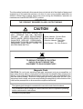
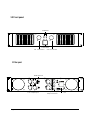
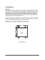
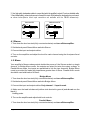
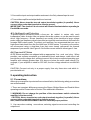
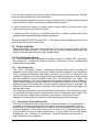
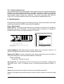
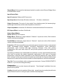
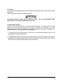
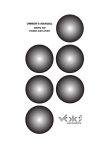
R
DIGISYNTHETIC
PROFESSIONAL POWER AMPLIFIER
DP45O
DP Series
Power Amplifier
USER MANUAL
TABLE OF CONTENTS
1. Safety Instructions
2
2. Introduction
2.1 Welcome
2.2 Unpacking
3
3
3. Description
3.1 Features
3.2 Frontpanel
3.3 Rearpanel
3
4
4
4. Installation
4.1 Stereo
4.2 Mono
4.3 Additional Load Protection
4.4 Required AC Mains
6
6
7
7
5. Operation
5.1 Precautions
5.2 Power Indicator
5.3 Protection Systems
5.3.1 Drive Protection
5.3.2 Transformer thermal Protection
5.3.3 Signal Limiting Circuit
7
8
8
8
8
9
6. Specifications
9
7. Service
12
Page 1
The information furnished in this manual does not include all of the details of design and
engineering of this particular product; not does it cover every possible application or
situation concerning its usage, which may occur during the installation, operation or
maintenance of said DIGISYNTHETIC product.
IMPORTANT
THE PRODUCT REQUIRES CLASS 2 OUTPUT WIRING.
CAUTION
TO PREVENT ELECTRIC SHOCK, DO
NOT REMOVE TOP OR BOTTOM
COVERS.
NO USER SERVICEABLE
PARTS INSIDE. REFER SERVICING TO
QUALIFIED SERVICE PERSONNEL.
DISCONNECT POWER CORD BEFORE
REMOVING REAR PANEL COVER TO
ACCESS GAIN SWITCH.
Shock Hazard - Do Not Enter
Choc Hasard - N*entrent
Schocke Hazard - Test Nicht
Betrete
Urto Hazard - Do Non Entrano
WARNING
TO REDUCE THE RISK OF ELECTRIC
SHOCK, DO NOT EXPOSE THIS
EQUIPMENT TO RAIN OR MOISTURE!
Magnetic Field
CAUTION: Do not locate sensitive high-gain equipment such as preamplifiers or
tape decks directly above or below this unit. Because this amplifier has a high power
density, it has a strong magnetic field which can induce hum into unshielded devices
that are located nearby. This field is strongest just above and below the unit. If an
equipment rack is used, we recommend locating the amplifier(s) at the bottom of the
rack and the preamplifier or other sensitive equipment at the top.
The lightning bolt triangle is used alert the user to the risk of electric shock
The exclamation point triangle is used to alert the user to important operating
and/or maintenance instructions.
Printed on recycled paper.
Page 2
2 Introduction
2.1 Welcome
Thank you for choosing DIGISYNTHETIC CO.LTD professional audio product. You
have joined a growing group of audio professionals who have turned to
DIGISYNTHETIC for the most advanced audio amplification products available. So
welcome to the DIGISYNTHETIC family! All DIGISYNTHETIC products have been
designed, engineered and manufactured to meet the demands of even the most critical
sound reinforcement professional.
Please read this manual carefully. It contains important and helpful information to enable
you to get the DIGISYNTHETIC performance out of your new product. If you plan to use
this amplifier in either of the 2 available Mono modes, please refer to section 2.2
1.1 Unpacking
Please unpack and inspect your new amplifier for any damage that may have occurred
during transit. If damage is found, notify the Transportation Company immediately. Only
you, the consignee, may initiate a claim with the carrier for damage which occurred
during shipment. Remember to save all packing materials in the unlikely event your unit
should ever need to be returned to the factory for service of any kind.
3 Description
3.1 Features
□Rugged, road-worthy professional power amplifier. E.I.A. Standard 19" (48.3cm) rackmountable chassis.
□ DP Series "Logic Output " circuitry generates large voltage swings while avoiding
electrical stress on the output stages. This results in low distortion and high reliability.
□ Front panel power switch with turn-on delay for loudspeaker protection.
□ Patented Output Device Emulation Protection keeps the amplifier working under
extreme conditions.
□ High damping factor provides superior control over low frequency drivers for a clean,
accurate low end.
□ Safe with any load. Bridge-Mono and Parallel-Mono modes offer optimal loadmatching performance.
□ Complete protection against shorted outputs, mismatched loads, overheating, DC
input/output and high frequency overload, full internal fault protection.
□ Balanced XLR inputs with balanced direct XLR output. Optional barrier block input
connectors are available with the PM-BB accessories.
□ Efficient heat sinks and self-contained forced air cooling system, dissipate heat
quickly and evenly for extra amplifier protection and greater power output.
Page 3
3.2 Front panel
Indicators
CH.2
CH.1
Power Switch
Ch1. Level Control
Ch2. Level Control
3.3 Rear panel
MODE SWITCH
AC 220V ±10%/ 50Hz-60Hz
1-Ch.1 Output Input
2-Ch.2 Output Input
Page 4
Binding Post andSpeakon
Output Connectors
Power
cord
4 Installation
Installation
Always reduce volume by turning level controls fully counterclockwise when either
connecting or disconnecting cables to the amplifier. This reduces the chance of an
audio "spike" that could possibly cause loudspeaker damage.The guidelines below
are provided to help you get your amplifier installed and ready to go quickly and
easily. Be sure to follow the instructions in Sections 2.1 and 2.2 for the selected
mode of operation. Additional information on input sensitivity, load protection and
required AC mains is provided in Section 2.3.
1. Install the amplifier in a standard 19-inch (48.3 cm) rack, or place it on a stable
surface. The mounting dimensions are 19-inch (48.3 cm) wide, 3.5-inch (8.9 cm) tall
and 17.7-inch (44.9 cm) deep behind the mounting surface.
IMPORTANT! ALLOW FOR ADEQUATE VENTILATION.
43.5cm
AIR FLOW
AIR FLOW
IMPORTANT: Be sure the back of
the amplifier is supported
AMPLIFIER
(TOP VIEW)
AIR FLOW
AIR FLOW
FRONT OF AMPLIFIER
Fig.2.4 Do Not Block Air Flow
Page 5
2. Use high-quality loudspeaker cables to connect the load to the amplifier's outputs. Do not use shielded cable.
3. Use shielded cables to connect audio sources to the amplifier's inputs. Either balanced or unbalanced wiring can be used
as shown below.(Barrier block input connectors are available with the PM-BB accessories).
BALANCED
GND
-
1
2
3
SHIELD
1
2
+
FROM
PREAMPLIFIER
INPUT
UNBALANCED
+
3
+
FROM
PREAMPLIFIER
INPUT
+
SHIELD
SHIELD
4.1 Stereo
1. Turn down the level controls (fully counterclockwise) and turn off the amplifier.
2. Set the back panel Stereo/Mono switch to Stereo.
3. Connect the input and output cables .
4. Turn on the amplifier and adjust the level for each channel using the front panel level
controls.
4.2 Mono
Your amplifier's Mono modes provide double the power of the Stereo mode in a single
channel. In Bridge-Mono mode, the outputs are wired for twice the output voltage. In
Parallel-Mono mode, the inputs are paralleled to link the two channels. Bridge-Mono
mode is provided for loads with impedance greater than 4 Ohms. Parallel-Mono mode
should be used with loads of 4 Ohms .
Bridge-Mono
1. Turn down the level controls (fully counterclockwise) and turn off the amplifier.
2. Set the back panel Stereo/Mono switch to Bridge-Mono.
3. Connect the input and output cables. Only channel 1 input is used.
4. Make sure the load is balanced (neither side shorted to ground) and do not use the
black (-)
binding posts.
5. Turn on the amplifier and adjust both level controls.
Parallel-Mono
1. Turn down the level controls (fully counterclockwise) and turn off the amplifier.
Page 6
3. Connect the input and output cables as shown in the Only channel input is used.
4. Turn on the amplifier and adjust both level controls.
CAUTION: Never strap the two red output terminals together (in parallel). Never
connect either red output terminal to chassis ground.
IMPORTANT: The channel 2 level control will remain illuminated when operating in
Parallel/M-ono mode.
4.3 Additional Load Protection
To protect against excessive power, a fuse can be added in series with each
loudspeaker cable. A single fuse can protect the entire system, or can be used for each
driver. High frequency drivers (tweeters) are usually more sensitive to large voltage
peaks, while low-frequency drivers (woofers) are typically most sensitive to the heat from
average RMS output power. To protect your tweeters, we recommend that you use a
high-speed instrument fuse like the Little fuse 361000 series. To protect your woofers,
we recommend using a slow-blow fuse that more closely represents the thermal
response of your woofer. Use Figure 2-6 to find the correct value for either type of fuse.
4.4 RequiredAC Mains
All DP Series amplifiers are shipped with an appropriate line cord and plug. When
possible, use a power receptacle on a dedicated circuit; and always, make sure it will
provide the correct voltage and sufficient current. We do not recommend operating your
amplifier with voltages greater than 10% above or below the unit's rated voltage. For
example, if your amplifier is rated for 220 VAC, the line voltage should not exceed 240
VAC.
CAUTION: Connect unit only to a proper supply. Use only three wire cord which is
provided with unit.
5.operating instruction
5.1 Precautions
Although your amplifier is protected from external faults, the following safety precautions
are recommended:
1. There are important differences among the Stereo, Bridge-Mono and Parallel-Mono
operating modes. Please refer to Section 2 for additional information.
2. WARNING: Do not change the position of the stereo/mono switch unless the
amplifier is first turned off .
CAUTION: Never strap the two red output terminals together (in parallel). Never
connect either red output terminal to chassis ground.
Also, make sure the Stereo/Mono switch is set to the proper position.
3. Use care when making connections, selecting signal sources and controlling the
output level.
Page 7
4. Do not short the ground lead of an output cable to the input signal ground. This will
form a ground loop and may cause oscillations.
5. Do not operate the amplifier from AC mains in excess of 10% variation above or below
the selected line voltage, and only at the specified line frequency.
6. Never connect the output to a power supply output, battery or power main. Such
connections may result in electrical shock.
7. Tampering with circuitry by unqualified personnel or making unauthorized circuit
changes may be hazardous and invalidates warranty.
Remember DIGISYNTHETIC Audio INC., is not liable for any damage that results from
overdriving other system components.
5.2 Power Indicator
When illuminated, the green power indicator (the volume control) shows that the
amplifier has been turned on. It is driven only by the low-voltage power supply and
does not indicate the status of the high-voltage supply.
5.3 Protection Systems
DP Series amplifiers have extensive protection systems, including TPC, protection,
drive protection, transformer thermal protection, and fuses or circuit breakers that
protect the power supplies.
5.3.1 Drive Protection
The Drive Protection System temporarily removes output drive to protect the
amplifier and its loads. Drive Protection System can be activated in two situations.
First, if dangerous subsonic frequencies or direct current (DC) is detected in the
amplifier's output, the unit will activate its DC/low-frequency protection circuitry, which
puts the amplifier in Drive Protection mode. This mode protects the loads and
prevents oscillations. The unit resumes normal operation as soon as the amplifier no
longer detects dangerous output. Although it is extremely unlikely that the DC/lowfrequency protecti-on system will ever be activated, improper source materials like
subsonic square waves or input over-loads, that excessively clip the input signal, can
activate this system.
The amplifier's protection system will activate the amplifier's Drive Protection mode
in rare situations where heavy common-mode current is detected in the output. The
unit should never output heavy common-mode current unless its circuitry is
damaged. Activating Drive Protection mode helps prevent further damage.
5.3.2 Transformer Thermal Protection
All DP Series amplifiers have Transformers Thermal Protection. This protection is
activated in unusual situations where the unit's transformer temperature rises to
unsafe levels. Under these abnormal conditions, the unit will removes output drive
to protect amplifier.. The fan will continue to run in all units. The amplifier will return
to normal after it cools to a safe temperature. It is very unlikely that your DP Series
amplifier will ever activate its Transformer Thermal Protection as long as it is
operated within rated conditions.
Page 8
5.3.3 Signal Limiting Circuit
This internal limiting circuit automatically reduce gain because of a significant deviation
between input and output signal flow, preventing occurrence of gross non-linearity
conditions inside the amplifier caused by overdrive, overload or defect, and keeps the
signal shape unaltered under any conditions. The circuit keep signal flow distortion
under 0.5%, and thus guarantees clean sound and effective speakon protection.
6. Specifications
All amplifier specifications apply to the following settings: Stereo mode with 8-ohm loads
and an input sensitivity of 32dB, unless otherwise specified.
Power Specification
Output Power: The following specifications are guaranteed minimums for standard 1
kHz power. For more information, see the power matrix in Figures 3.1 through 3.2
(DIGISYNTHETICimum average power @ 0.1% THD +N).
Heatsink temperature Temperature Protect Circuit (TPC)
90 c
80 c
70 c
60 c
90 C Mute the signal
Automatic
Out put the signal
80 C
At 75° C
60
C
TPC Limiter active
DIGISYNTHETIC. fan speed
50 c
40 c
CHANNEL 1
LEVEL CONTROL
CHANNEL 2
LEVEL CONTROL
30 c
20 c
10 c
Fig.2.1 Front Panel Level Control
The following diagram illustrates the actions taken by the Thermal
Management System:
Min. fan speed,
TPC normal
Fan speed
0 c
Amplifier: DP Series
Fig.2.2 TPC
Load Impedance: Safe with all types of loads. Rated at 4 to 8 ohms in Stereo, 4 to
8ohms in Bridge-Mono and 4 to 8 ohms in Parallel-Mono mode.
Required AC Mains: Current, frequency and voltage requirements are provided on
each unit's back panel. All models draw 90 Watts or less at idle.
DP450: (220/50Hz)
Draws up to 10 amps of current.
AC Connector: An appropriate AC line cord and plug are provided. 110/220 VAC,
50Hz/60Hz units have a standard 3-wire, 15-amp grounded connector (NEMA 515P).
Controls
Power: A front panel rocker switch is used to turn the amplifier on and off.
Level: A front panel rotary potentiometer for each channel is used to control the output
level.
Page 9
Stereo/Mono:A three-position back panel switch is used to select Stereo, Bridge-Mono
or Parallel-Mono mode.
Input/Output Data
Input Connector: Balanced XLR connector.
Input Impedance: Nominally 20k ohms, balanced; 10 k ohms, unbalanced.
Output Connector: Two sets of color-coded 5-way binding posts (for banana plugs,
spade lugs or bare wire) and two sets of speakon connectors.
Output Impedance: Less than 10 milliohms in series with less than 2 microhenries.
DC Output Offset: Less than 10 millivolts.
Output Signal Modes
Stereo: Balanced, two-channel.
Bridge-Mono: Balanced, single-channel. Channel 1 inputs are active; Both channel
volume controls are available.
Parallel-Mono: balanced, single-channel. Channel 1 inputs are active; Both channel
volume controls are available.
Protection DP Series amplifiers are protected against shorted circuits or mismatched
loads, overloaded power supplies, excessive temperature, chain destruction
phenomena, input overload and high frequency blowups. They also protect
loudspeakers from input and output DC and provide protection from turn-on/turn-off
transients.
If operating conditions are unreasonable, the patented circuitry proportionally limits the
drive level to protect the output transistors, particularly in the case of elevated
temperature. A thermal switch imbedded on the heat-sink protects the output device
from overload. In the rare event that a transformer overheats, the thermal switch turns
the power off, waits until the unit has cooled to a safe temperature and then resets itself.
Turn On: Five second delay with no dangerous transients. Contact DIGISYNTHETIC
Audio Inc. if you need to change the delay.
Construction
Durable black finish on steel chassis with special
panel to front panels.
"flow-through" ventilation from rear
Cooling: Internal heat sinks and two 80mm high speed low noise cooling fan with auto
speed-control forced-air cooling for rapid, uniform heat dissipation.
Page 10
Dimensions: Standard 56 cm rack mount width (ElA RS-310-B), 15 cm height and 47
cm depth behind the mounting surface.
Approximate Weight: Center of gravity is 10 inches (25.42 cm) behind front mounting
surface.
In an effort to provide you with as much information as possible about the high
power-producing capabilities of your amplifier, we have created the following
power matrices:
need to change the delay.
DP450
300W
500W
900W
300W
500W
20Hz-20kHz+/_0.5dB
+0dB/-0.3dBfrom 20Hz to 20kHz at 1 watt
+/_0.1degrees from 10Hz to 20kHz at 1 watt
>98dB
≤0.01% Rated Power@8Ω
≤0.01% Rated Power@8Ω 1kHZ
>300@1kHz/8 ohms
>60dB
40v/μs (Stereo)
10K/20K ohms, unbalanced or balanced
56cm x 47cm x 15cm
~220V 50/60Hz
FUSE:T10A
FUSE:T12A
FUSE:T15A
Page 11
5. Service
This unit has very sophisticated circuitry and should only be serviced by a fully trained
technician.
This is why each unit bears the following label:
CAUTION
To prevent electric shock, do not remove covers. No user serviceable parts
inside. Refer servicing to a qualified technician.
5.1 Worldwide Service
Service may be obtained from your local authorized agent. To obtain service, simply
present your sales receipt as proof of purchase along with the defective unit to an
authorized agent. They will handle the necessary paperwork and repair. Remember to
transport your unit in the original factory packaging.
1. To ensure the safe transportation of your unit to the authorized agent, ship it in an
original factory-packing container.
2. Do not ship the unit in any kind of rack. Ignoring this warning may result in extensive
damage to the unit and the equipment rack. Accessories are not needed. Do not send
the instruction manual, cables and any other hardware.
Page 12