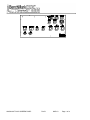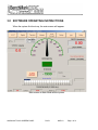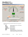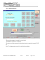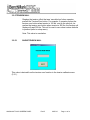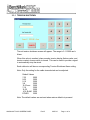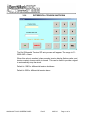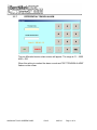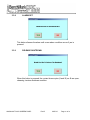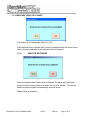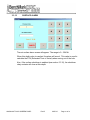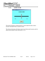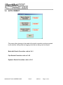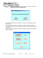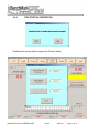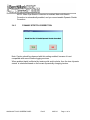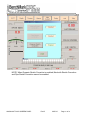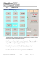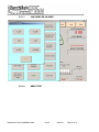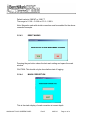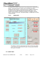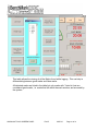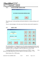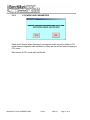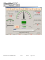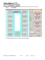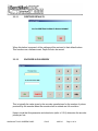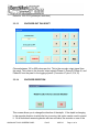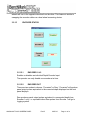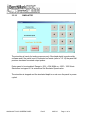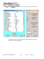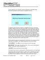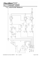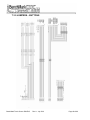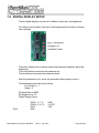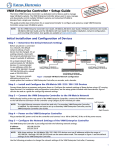
1
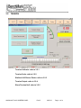
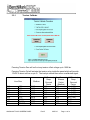
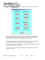
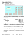
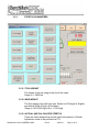
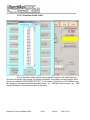
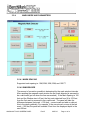
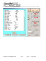
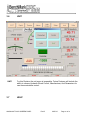
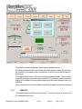
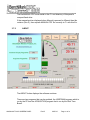
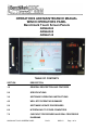
OPERATIONS AND MAINTENANCE MANUAL
WINCH OPERATORS PANEL
Benchmark Touch Screen Panels
AMS4A044
AMS4A048
AMS4A148
TABLE OF CONTENTS
SECTION
DESCRIPTION
1.0
GENERAL DESCRIPTION AND FEATURES
2.0
SPECIFICATIONS
3.0
SOFTWARE OPERATING INSTRUCTIONS
4.0
WELLSITE OPERATING SUMMARY
5.0
SOFTWARE UPDATE PROCEDURES
6.0
INTERFACING TO OTHER COMPUTERS
7.0
CHECKOUT PROCEDURES AND REAL PROCESSOR
DIAGRAMS
AMS4A148 TOUCH SCREEN PANEL
Rev B
MAR 10
Page 1 of 90
8.0
PARTS LIST
9.0
CABLE DRAWINGS
AMS4A148 TOUCH SCREEN PANEL
Rev B
MAR 10
Page 2 of 90
1.0
INTRODUCTION
1.1
GENERAL DESCRIPTION
This panel is used to acquire and display depth and tension data from a wireline
logging winch unit. The panel provides the operator a means to set and make
adjustments to the data as necessary. Depth is displayed from data provided from an
encoder mounted on a measuring device. The tension data is provided by a load pin
and is also passed through to the acquisition system. The panel will operate with the
Kerr AM5K Dual Wheel Measuring Device for both open hole and cased hole services.
The system consists of two main components, the real time acquisition board and
the PC. The acquisition board provides power to and processes the signals from
the encoders, load pin, and magnetic mark detector. This board operates
independent from the PC and is instantly on when power is applied. It also is
connected to displays for depth and tension. This allows depth and tension to be
displayed immediately on power up and always be displayed regardless of the PC
status.
The PC uses an Intel based high speed processor running MS Windows XP
embedded. The PC includes a color touch screen for operator input and command
entry. The PC is Ethernet ready for connection to the internet for remote display and
control.
AMS4A148 TOUCH SCREEN PANEL
Rev B
MAR 10
Page 3 of 90
1.2
HARDWARE FEATURES
Power Input
12 - 24 VDC
120 – 240 VAC 50/60 HZ
Internal UPS with 2 hour battery
Internal PC board
Intel based personal computer board
1 gb solid state media device
Embedded windows XP operating system
Three USB ports (2 front, 1 rear)
1 RS232 port
RJ 45 Ethernet port
USB Mouse / Keyboard included
Color Display
TFT LCD
Backlit
400 NITS Sunlight readable
Touch Screen Interface (replaces current key pad)
5 wire resistive
USB interface
Real Time Acquisition board
BenchMark Wireline Products proprietary design
8051 compatible microprocessor based
Provides power to encoders, mag mark detector, and load cell
Processes encoder quadrature, mag mark signal, and load cell
Runs independent of PC board
Connected to digital displays for real time display of depth and
tension
Overtension Relay Contact Closure output
Analog output interface
Encoder quadrature output
0 – 10vdc tension output
4-20ma tension output
Dual Intercom system
AMS4A148 TOUCH SCREEN PANEL
Rev B
MAR 10
Page 4 of 90
1.3
USER INTERFACE FEATURES
Total Tension numeric graphic
Incremental or Differential tension meter graphic
Meter reset button graphic (touch screen control)
Over_tension Warnings and Shutdown settings for both Differential and
Total Tension readings (touch screen activated)
Numeric graphic display of Last Mark Depth
Magnetic Mark or CCL depth table display
MMD or CCL selection button (touch screen control)
Mark Detection Window (touch screen control)
Mark Spacing Window (touch screen control)
Magnetic Mark Automatic Correction (touch screen control)
CCL depth numeric graphic
CCL meter graphic
CCL depth offset setting (touch screen control)
Tension Calibration Setup Window (touch screen control)
Encoder Resolution Settings (PPR value set by touch screen control)
Single / Dual Encoder Selection: (touch screen control)
Encoder 1, Encoder 2, or Both
Both (reads both encoders every 10 msec and takes value from the
one that moved the furthest since the previous reading.
AMS4A148 TOUCH SCREEN PANEL
Rev B
MAR 10
Page 5 of 90
2.0
SPECIFICATIONS
FRONT
SIDE
REAR
AMS4A148 TOUCH SCREEN PANEL
Rev B
MAR 10
Page 6 of 90
AMS4A148 TOUCH SCREEN PANEL
Rev B
MAR 10
Page 7 of 90
WEIGHT:
13 LBS
5.92 KG
POWER REQUIREMENTS:
INPUT VOLTAGE:
12 VDC OR 115 VAC 60 HZ
INPUT CURRENT:
4 AMPS STARTUP SURGE
3 AMPS NORMAL OPERATION
OPERATING TEMPERATURE
Min
Max
14
149 degrees F
-10
65 degrees C
STORAGE TEMPERATURE
Min
Max
-22
158 degrees F
-30
70 degrees C
AMS4A148 TOUCH SCREEN PANEL
Rev B
MAR 10
Page 8 of 90
3.0 SOFTWARE OPERATING INSTRUCTIONS
When the system first boots up, the main screen will appear.
Main screen in Mark Mode without power
AMS4A148 TOUCH SCREEN PANEL
Rev B
MAR 10
Page 9 of 90
Main screen in Mark Mode with power
Most of the commands are accessed through the buttons across the top
of the screen.
EXIT
DEPTH
TENSION
ALARMS
AUTOCORRECT
SETUP
UNITS
HELP
AMS4A148 TOUCH SCREEN PANEL
Exits the program and returns to MS-Windows.
Refer to section 3.1
Refer to section 3.2
Refer to section 3.3
Refer to section 3.4
Refer to section 3.5
Refer to section 3.6
Invokes the Help Screen. This document can be
displayed from the help menu. Also, the program
revision information is displayed. Refer to section 3.7
Rev B
MAR 10
Page 10 of 90
3.1
DEPTH
3.1.1 Set Depth
Invokes the keypad. The new depth can be directly entered using the keypad.
The valid range of depths are listed.
3.1.2 Raw1 Depth
Displays the current uncorrected encoder 1 depth
3.1.3 Raw2 Depth
Displays the current uncorrected encoder 2 depth
3.1.4 Depth Shim
AMS4A148 TOUCH SCREEN PANEL
Rev B
MAR 10
Page 11 of 90
Adds or subtracts depth continually.
If 1 is entered then 1 foot or 1 meter will be added every 1000 feet or 1000
meters.
If -.2 is entered then .2 feet or .2 meters will be subtracted every 1000 feet or
1000 meters.
3.1.5 Add / Subtract Increment
Default is 0.1 meters – operator can set this increment up to 1 meter.
3.1.6 Add .1 Mt
If line is moving, 0.1 meter is added over the next 1 meter interval. The gradual
correction is not performed until the line moves. Note: If line is moving and the
operator presses add 0.1 meter and then presses add 0.1 meter again while
the panel is in process of adding the first 0.1 meter, the total will not be 0.2
meters. If line is not moving, the increment is added immediately.
3.1.7 Subtract .1 Mt
If line is moving, 0.1 meter is subtracted over the next 1 meter interval. The
correction is not performed until the line moves. Note: If line is moving and the
operator presses add 0.1 meter and then presses add 0.1 meter again while
the panel is in process of adding the first 0.1 meter, the total will not be 0.2
meters. If line is not moving, the increment is subtracted immediately.
3.1.8 Offset
Displays a snapshot of the cumulative additions and/or subtraction that were
performed.
AMS4A148 TOUCH SCREEN PANEL
Rev B
MAR 10
Page 12 of 90
3.2
TENSION
Tension Calibrate: refer to 3.2.1
Tension Scale: refer to 3.2.2
Shallow & Hi Sheave Factor: refer to 3.2.3
Tension Output: refer to 3.2.4
Show Tension Null: refer to 3.2.5
AMS4A148 TOUCH SCREEN PANEL
Rev B
MAR 10
Page 13 of 90
3.2.1
Tension Calibrate
Pressing Tension Zero will null out any tension offset voltage up to 1000 lbs.
Pressing Tension Cal will activate the tension relay inside the panel which will provide
12VDC to shunt cal line on pin G. The load pin should then return a calibrated signal.
Line Size
.219
.280
.313
.375
.406
.438
.469
.474
7/32
9/32
5/16
3/8
10.3 mm
7/16
15/32
SLAM
OTHER
Shallow
6110
4806
4615
4160
3250
3576
3315
3250
3250
AMS4A148 TOUCH SCREEN PANEL
(HI Tension)
Deep
Grooved
Factor
6110
4806
4615
4160
3250
3576
7095
6750
6500
Rev B
Non-Grooved
Sheave
Factor
(Shallow)
1.88
1.48
1.42
1.28
1.19
1.10
1.02
1.00
1.00
MAR 10
(HI Tension)
Deep
Grooved
Factor
n/a (1.00)
n/a (1.00)
n/a (1.00)
n/a (1.00)
n/a (1.00)
n/a (1.00)
2.42
2.30
2.00
Page 14 of 90
3.2.2
TENSION SCALE
The Tension Scale Screen allows the changing of both Bar Meter Scale near the
bottom and the Needle Gauge Scale at the center of the screen. It also allows the
Gauge Scale to be used either in a Differential or Incremental scale.
Incremental tension provides a high resolution tension scale. It must be periodically
reset as tension increases or decreases to keep it from “pegging out”.
Differential tension provides a delta tension reading. The meter will slowly reset itself
to 0 so the reset switch is not necessary.
A note at the middle-right of the screen advises you of your measurement units, i.e.
kilograms or pounds.
AMS4A148 TOUCH SCREEN PANEL
Rev B
MAR 10
Page 15 of 90
3.2.3 SHEAVE FACTOR (SHALLOW & HI)
Sheave Factor is related to the loadcell angle. Loadcell angle is used to compensate
when a loadcell is not hung vertically (i.e. bottom sheave). Enter the value derived
from the formula:
Factor =
1
Examples:
cosine (angle)
30 degrees = 1.035
45 degrees = 1.082
2
90 degrees = 1.414
120 degrees = 2.000
Note: This function is only changeable when line size selected is “Other”. This option
would be selected if, for example, the inline load pin in the Benchmark 5K Measuring
Head was not utilized as the tension measuring device.
Sheave Factor is pre-determined for the 8 built-in line sizes using the 5K Head
Benchmark and cannot be changed.
Also, additionally, a deep grooved wheel factor is used, if enabled, and is predetermined and built-in and cannot be changed.
Note: Sheave factor (HI) is meaningful when the HI tension wheel option is chosen
‘YES’. Refer to section 3.5.1- Line size setup. This wheel option is available only for
the 5K head.
AMS4A148 TOUCH SCREEN PANEL
Rev B
MAR 10
Page 16 of 90
3.2.4 TENSION OUTPUT
This provides a means to re-scale the output signal.
The default is 12,500 lbs = 10 volts out.
This option would be necessary for jobs where tension is expected to exceed 12,500
lbs.
Note: The logging system needs to be calibrated accordingly.
AMS4A148 TOUCH SCREEN PANEL
Rev B
MAR 10
Page 17 of 90
3.2.5 TENSION NULL
Displays the tension offset that was ‘cancelled-out’ when operator
pushed the Tension Zero button. For example, if operator pushes the
tension zero button when tension is 100 lbs. and on the next job, he
pushes the tension zero button when tension is 200 lbs, the tension null
display will read 300 lbs. This null is reset to zero when restore defaults
is pressed (refer to setup menu).
Note: This value is cumulative.
3.2.5.1
SHOW TENSION NULL
This value is derived from the tension zero function in the tension calibrate menu
(3.2.1).
AMS4A148 TOUCH SCREEN PANEL
Rev B
MAR 10
Page 18 of 90
3.3
ALARMS
Tension Shutdown: refer to 3.3.1
Tension Alarm: refer to 3.3.2
Test Alarm: refer to 3.3.3
Test Shutdown: refer to 3.3.4
Test Load Cell Shunt: refer to 3.3.5
Differential Tension Shutdown: refer to 3.3.6
Differential Tension Alarm: refer to 3.3.7
Alarm Off: refer to 3.3.8
Release Shutdown: refer to 3.3.9
Release LC Shunt: refer to 3.3.10
Surface Shutdown: refer to 3.3.11
AMS4A148 TOUCH SCREEN PANEL
Rev B
MAR 10
Page 19 of 90
Surface Alarm: refer to 3.3.12
Max Depth Alarm: refer to 3.3.13
Alarm Volume: refer to 3.3.14
Fixed Well Marker Depth: refer to 3.3.15
AMS4A148 TOUCH SCREEN PANEL
Rev B
MAR 10
Page 20 of 90
3.3.1 TENSION SHUTDOWN
The set tension shutdown screen will appear. The range is 0.1-19999 and >
Alarm.
When this value is reached, alarm sounds, tension display flashes value, and
tension contact closure switch is closed. This can be used to provide a signal
to automatically stop the winch.
Each cable size will have a corresponding Tension Shutdown Alarm setting.
Note: Only the setting for the cable size selected can be adjusted.
Default Values
7-32
2000
9-32
3000
5-16
3500
3-8
3500
10.33 mm
3500
7-16
3500
15-32
3500
.474 SLAM 3500
OTHER
3500
Note: The default values are restored when restore defaults is pressed.
AMS4A148 TOUCH SCREEN PANEL
Rev B
MAR 10
Page 21 of 90
3.3.2
TENSION ALARM
The set tension alarm screen will appear. The range is 0.1 – 19999 and < S/D
When preset tension value is reached, alarm sounds and "TENSION ALARM" flashes
on the screen.
Each cable size will have a corresponding Tension Alarm setting.
Note: Only the setting for the cable size selected can be adjusted. The default values
are restored when restore defaults is pressed.
Default Values
7-32
9-32
5-16
3-8
10.3 mm
7-16
15-32
.474 SLAM
OTHER
AMS4A148 TOUCH SCREEN PANEL
1500
2400
2400
2400
2400
2400
2400
2400
2400
Rev B
MAR 10
Page 22 of 90
3.3.3
TEST ALARM
This button will sound the alarm when yes is pressed. This can be used
to verify the alarm is working and to determine if the volume is adequate.
3.3.4
TEST SHUTDOWN
When this button is pressed, the shutdown relay contacts are shorted
when yes is pressed. This can be used to test the winch shutdown
mechanism or any other mechanism that uses these contacts.
3.3.5
TEST LOAD CELL SHUNT
This feature is for testing the load cell shunt only. A tension calibration is
not performed with this feature.
AMS4A148 TOUCH SCREEN PANEL
Rev B
MAR 10
Page 23 of 90
3.3.6
DIFFERENTIAL TENSION SHUTDOWN
The Set Differential Tension S/D entry screen will appear. The range is 0.15000 AND > Alarm.
When this value is reached, alarm sounds, tension display flashes value, and
tension contact closure switch is closed. This can be used to provide a signal
to automatically stop the winch.
Default is 1000 for differential tension shutdown.
Default is 500 for differential tension alarm.
AMS4A148 TOUCH SCREEN PANEL
Rev B
MAR 10
Page 24 of 90
3.3.7
DIFFERENTIAL TENSION ALARM
The set differential tension alarm screen will appear. The range is 0.1 – 2000
AND < S/D.
When this setting is reached the alarm sounds and "DIFF TENSION ALARM"
flashes on the screen.
AMS4A148 TOUCH SCREEN PANEL
Rev B
MAR 10
Page 25 of 90
3.3.8
ALARM OFF
This button silences the alarm until a new alarm condition occurs if yes is
pressed.
3.3.9
RELEASE SHUTDOWN
When this button is pressed, the contact closure pins (A and B) on J8 are open,
releasing tension shutdown condition.
AMS4A148 TOUCH SCREEN PANEL
Rev B
MAR 10
Page 26 of 90
3.3.10 RELEASE LOAD CELL SHUNT
This feature is fro testing only (refer to 3.3.5).
If the load cell shunt is tested, then it must be released using the above menu
item. A tension calibration is not performed with this feature.
3.3.11
SURFACE SHUTDOWN
When the surface alarm depth value is reached, the alarm will sound and
tension contact closure switch is closed if this is set to ‘enable’. This can be
used to provide a signal to automatically stop the winch.
Default value is ‘disabled’.
AMS4A148 TOUCH SCREEN PANEL
Rev B
MAR 10
Page 27 of 90
3.3.12
SURFACE ALARM
The set surface alarm screen will appear. The range is 0 – 304 Mt.
When this depth value is reached, the alarm will sound. This value is used to
calculate the ETA (Estimated Time of Arrival) when coming out of the hole.
Also, if the surface shutdown is enabled (see section 3.3.10), the shutdown
relay contacts will close at this depth.
AMS4A148 TOUCH SCREEN PANEL
Rev B
MAR 10
Page 28 of 90
3.3.13
MAX DEPTH ALARM
The set max depth alarm screen will appear. The range is surface alarm – 9144
Mt.
When depth value is reached the alarm will sound and a message will flash on
the main screen.
This value is used to calculate the ETA (estimated time or arrival) when going
downhole (to T.D. for example).
AMS4A148 TOUCH SCREEN PANEL
Rev B
MAR 10
Page 29 of 90
3.3.14
ALARM VOLUME
This button will bring up a slider bar which is used to adjust the alarm volume.
Use the "Test Alarm" button to test the volume.
This slider and the alarm will always revert to ‘loud’ when panel is power cycled or
when restore defaults is done (see section 3.5.10).
AMS4A148 TOUCH SCREEN PANEL
Rev B
MAR 10
Page 30 of 90
3.3.15 FIXED WELL MARKER DEPTH
This feature offers a visual alarm that notifies the operator when a depth of interest is
approaching.
The background color of the depth box will change color when depth is within +/- 20
and +/- 10 meters of the operator inputted fixed well marker depth.
AMS4A148 TOUCH SCREEN PANEL
Rev B
MAR 10
Page 31 of 90
3.4
AUTO CORRECT
This menu allows changes to be made to the stretch correction mode as required
by the wireline, drilling mud and logging tools that are being used on the job.
Mark with Stretch Correction: refer to 3.4.1
Pipe Stretch Correction: refer to 3.4.2
Dynamic Stretch Correction: refer to 3.4.3
AMS4A148 TOUCH SCREEN PANEL
Rev B
MAR 10
Page 32 of 90
3.4.1
MARK WITH STRETCH CORRECTION
This mode is enabled when the depth is to be corrected to magnetically marked
Wireline cable.
For accurate depth correction it is important to ensure that the mud and cable
parameters are correct and that tool weight is entered. Also ensure that proper line
size is chosen.
NOTE: When Mark with Stretch Correction is enabled, you cannot enable Dynamic
Stretch Correction
AMS4A148 TOUCH SCREEN PANEL
Rev B
MAR 10
Page 33 of 90
3.4.2
PIPE STRETCH CORRECTION
Enabling this causes depth to agree with ‘Driller’s Depth’
AMS4A148 TOUCH SCREEN PANEL
Rev B
MAR 10
Page 34 of 90
NOTE: When Pipe Stretch Correction is enabled, Mark with Stretch
Correction is automatically enabled, and you cannot enable Dynamic Stretch
Correction.
3.4.3
DYNAMIC STRETCH CORRECTION
Note: Caution should be observed with this setting enabled, because it is not
compatible with some Wireline logging services.
When enabled depth is affected by tension pulls and/or slacks, thus the term ‘dynamic
stretch’ is calculated based on the current dynamically changing tension.
AMS4A148 TOUCH SCREEN PANEL
Rev B
MAR 10
Page 35 of 90
NOTE: When Dynamic Stretch Correction is enabled, Mark with Stretch Correction
and Pipe Stretch Correction cannot be enabled.
AMS4A148 TOUCH SCREEN PANEL
Rev B
MAR 10
Page 36 of 90
3.5 SETUP SCREEN
The Setup Menu allows changes to the peripheral hardware.
Line Size: refer to 3.5.1
Head Type: refer to 3.5.2
Stretch Parameters: refer to 3.5.3
Mark Mode and Parameters: refer to 3.5.4
Mark Table: refer to 3.5.5
Show and Beep Marks Mode: refer to 3.5.6
Wheel Size: refer to 3.5.7
AMS4A148 TOUCH SCREEN PANEL
Rev B
MAR 10
Page 37 of 90
English/Metric Units: refer to 3.5.8
CCL Mode and Parameters: refer to 3.5.9
CCL Table: refer to 3.5.10
Restore Defaults: refer to 3.5.11
Encoder In Pulses/Rev.: refer to 3.5.12
Encoder Out Pulses/Ft.: refer to 3.5.13
Encoder Direction: refer to 3.5.14
Encoder Status: refer to 3.5.15
Simulator: refer to 3.5.16
Summary: refer to 3.5.17
AMS4A148 TOUCH SCREEN PANEL
Rev B
MAR 10
Page 38 of 90
3.5.1
LINE SIZE SETUP
The selection of the 9 built-in line sizes and the deep grooved (Hi-Tension) wheel is
specifically for use with the Benchmark 5K Head.
Select the line size by pressing the corresponding gray box. This menu also allows
the changing to a deep grooved wheel on the measuring head. This does NOT
change the tension output settings (refer to 3.2.4)
Note that line size must be set to Other (Not Inline) at this menu to allow
some other parameters to be set, as noted on their individual menu’s.
Note: ‘Other’ should be chosen if not using the Benchmark AM5K Head.
AMS4A148 TOUCH SCREEN PANEL
Rev B
MAR 10
Page 39 of 90
3.5.1.1
LINE SIZE FOR 3K HEAD
3.5.1.2
HEAD TYPE
AMS4A148 TOUCH SCREEN PANEL
Rev B
MAR 10
Page 40 of 90
If ‘3K Head’ is chosen then the line size for the 3K head menu is available.
If ‘5K Head’ is chosen then the line size for the 5K head menu is available.
If ‘other’ is chosen there is no corresponding line size menu; rather, wheel size,
and sheave factor menus are available.
AMS4A148 TOUCH SCREEN PANEL
Rev B
MAR 10
Page 41 of 90
3.5.3
STRETCH PARAMETERS
3.5.2.1 TOOL WEIGHT
The weight of the tool string at the end of the cable.
Range is 1-10000 lbs.
3.5.2.2 MUD WEIGHT
The fluid weight of the well bore fluid. Default is 8.30 lb/gal for English,
and default is 994.56 kg/cu.M for Metric.
Range is 120-12000 Kg/cu.M or 1-100 lb/gal.
3.5.2.3 ACTUAL AND CALCULATED STRETCH
These are static displays that provide useful information if a Stretch
Adjustment needs to be performed at T.D.
AMS4A148 TOUCH SCREEN PANEL
Rev B
MAR 10
Page 42 of 90
Calculated Stretch is the theoretical stretch based on depth, line size
(weight and stretch coefficient), mud weight, and tool string weight and
the theoretical tension.
Actual Stretch is calculated using all of the above parameters, except
that the actual tension is used in the stretch calculation.
3.5.2.4 LINE WEIGHT
If line size and/or head chosen is: ‘OTHER’, Then this value must be
centered for the stretch calculations to be accurate.
3.5.2.5 LINE VOLUME
If line size and/or head chosen is: ‘OTHER’, Then this value must be
centered for the stretch calculations to be accurate.
3.5.2.6 STRETCH COEFFICIENT
If line size and/or head chosen is: ‘OTHER’, Then this value must be
centered for the stretch calculations to be accurate.
AMS4A148 TOUCH SCREEN PANEL
Rev B
MAR 10
Page 43 of 90
3.5.2.7 View/Save Profile Table
This is the table of the location of the magnetic marks on the cable based on:
line size, line weight, line volume, line stretch coefficient, tool weight, and mud weight. Note
the text box labeled ‘FIRST MARK OFFSET’. For Example: If the value is 10.00 Meters, then
all numbers in the table reflect the theoretical mark…eg… 50M plus the first mark…eg… 10M
Equals 60 Meters for the actual location of the mark.
AMS4A148 TOUCH SCREEN PANEL
Rev B
MAR 10
Page 44 of 90
3.5.4
MARK MODE AND PARAMETERS
3.5.4.1 MARK SPACING
Supported mark spacing is: 10M, 20M, 25M, 50M, and 100 FT.
3.5.4.2 WINDOW SIZE
The amount of correction possible is determined by the mark window intervals.
After resetting the magnetic mark window the first mark detected is assumed to
be a valid mark (put on when the line was marked.) If the Mark Spacing is 100
feet and the Window size is 2 feet, the first mark detected from 98 to 102 feet
from the first mark is assumed to be a valid mark. The panel will take the
difference between (last mark + 100 feet) – current mark and add or subtract
this to the depth gradually. For example, if the current mark occurs at the last
mark + 102 feet, the panel will subtract 2 feet from the displayed depth in the
next 20 feet.
AMS4A148 TOUCH SCREEN PANEL
Rev B
MAR 10
Page 45 of 90
Default value is 0.88 MT or 2.89 FT
The range is 0.1 Mt – 0.9 Mt or 0.3 ft – 2.96 ft.
Note: Magnetic mark with stretch correction must be enabled for the above
correction example.
3.5.4.3
RESET MARKS
Pressing the yes button clears the last mark setting and opens the mark
window.
CAUTION: This should only be done before start of logging.
3.5.4.4
MARK CORRECTION
This is the static display of mark correction at current depth.
AMS4A148 TOUCH SCREEN PANEL
Rev B
MAR 10
Page 46 of 90
Line stretch due to tension is accounted for by entering the tool weight and fluid
density. A theoretical tension vs depth curve is calculated and used to
establish the mark locations. At each mark the error is added or subtracted to
the depth so that the depth will match the theoretical mark depth. As an
example, if a tool weight of 1000# and fluid weight of 8.3 lbs/gal is used the
mark at 10000 feet is 10.8 feet + the mark at surface. At 20000 feet it is 43 feet
+ mark at surface.
3.5.4.5
MARK RATIO
This display is useful for determining if the marks on the line are getting
weak. The ratio is calculated as the number of strong marks divided by
the number of all marks.
3.5.5 MARK TABLE
AMS4A148 TOUCH SCREEN PANEL
Rev B
MAR 10
Page 47 of 90
This table allows the viewing of all the Marks found while logging. This can help in
differentiating between good marks and false marks.
All detected marks are listed in the table but only marks with * listed in front are
considered good marks, i.e. marks that fall within the mark window, and are used by
the system.
AMS4A148 TOUCH SCREEN PANEL
Rev B
MAR 10
Page 48 of 90
3.5.6
SHOW AND BEEP MARKS MODE
The choices are: to show and beep valid marks (default) or to show and beep on all
marks.
There is a new message on the main screen that shows what mode the panel is in.
3.5.7
WHEEL SIZE
This setting allows you to change the size of the depth measuring wheel that is used
to measure depth. To use a different measuring head from the Benchmark head, this
setting will need to be changed to match the wheel size of the new head.
To change Wheel Size, the line size must be first set to OTHER. At this
the load cell angle sheave factor will also need to be set (refer to section 3.2.3).
Default value is 2ft or .6096 meters
AMS4A148 TOUCH SCREEN PANEL
Rev B
MAR 10
Page 49 of 90
time,
Note: Depth shim (refer to section 3.1.4) affects depth in a manner similar to wheel
size. Care should be exercised when setting these values.
3.5.8
ENGLISH/METRIC UNITS
This menu allows you to select the display units for either depth or tension.
AMS4A148 TOUCH SCREEN PANEL
Rev B
MAR 10
Page 50 of 90
3.5.9
CCL MODE AND PARAMETERS
Depth could change when changing from magnetic mark correction mode to CCL
mode because magnetic mark corrections (if any) are zeroed-out when changing to
CCL mode.
Main screen in CCL mode will look like this:
AMS4A148 TOUCH SCREEN PANEL
Rev B
MAR 10
Page 51 of 90
AMS4A148 TOUCH SCREEN PANEL
Rev B
MAR 10
Page 52 of 90
3.5.10
CCL TABLE
This table allows the viewing of Collars found while logging
AMS4A148 TOUCH SCREEN PANEL
Rev B
MAR 10
Page 53 of 90
3.5.11
RESTORE DEFAULTS
When this button is pressed, all the settings will be restored to their default values.
This functions as a software reset. Depth will also be zeroed.
3.5.12
ENCODER IN PULSES/REV
This is typically the value given by the encoder manufacturer for the number of pulses
produced by the encoder when the encoder shaft is rotated one full revolution.
Keep in mind that this parameter and wheel size (refer to 3.5.6) determine the encoder
pulses per foot.
AMS4A148 TOUCH SCREEN PANEL
Rev B
MAR 10
Page 54 of 90
Default is 1200 PPR (pulses per revolution)
3.5.13
ENCODER OUT PULSES/FT.
Choose between 100 or 600 pulses per foot. This is the encoder output signal from
the panel. This refers to the encoder output signals Phase A, Phase B, Phase A/, and
Phase B/ from the panel to the logging system. (Connector J7 pins 2,3,14,15)
3.5.14
ENCODER DIRECTION
This screen allows you to change the direction of the depth. If the depth is changing
in the opposite direction to which the line is moving, this option can be used to correct
it. On a dual wheel measuring device with two encoders, the encoder on one of the
AMS4A148 TOUCH SCREEN PANEL
Rev B
MAR 10
Page 55 of 90
wheels will turn in the opposite direction from the other. This feature is similar to
swapping the encoder cables on a dual wheel measuring device.
3.5.15
ENCODER STATUS
3.5.15.1
ENCODER 1 & 2
Enables or disables an individual Depth Encoder Input.
The operator can only disable one encoder at a time.
3.5.15.2
ENCODER OUT
There are two modes to choose: “Corrected” or Raw. “Corrected” will produce
panel output pulses equivalent to the corrected depth displayed on the front
panel displays.
Raw produces panel output pulses equivalent to uncorrected depth from
Encoder 1 only, i.e. equivalent direct Raw pulses from Encoder 1 will go to
logging system.
AMS4A148 TOUCH SCREEN PANEL
Rev B
MAR 10
Page 56 of 90
3.5.16
SIMULATOR
The simulator is handy for testing purposes only. Simulated depth is produced by
software and if the panel is set to corrected out mode (refer to 3.5.14) the panel will
produce simulated corrected output pulses.
Enter speed to be simulated. Range is -304 - >304 M/Min or -1000 – 1000 ft/min.
Simulation is stopped if 0 is entered as Set Simulator Speed value.
The simulator is stopped and the simulated depth is re-set once the panel is powercycled.
AMS4A148 TOUCH SCREEN PANEL
Rev B
MAR 10
Page 57 of 90
3.5.17
SUMMARY
The Summary Menu is a quick reference to what all parameters are set to in
the panel. This is a static display.
AMS4A148 TOUCH SCREEN PANEL
Rev B
MAR 10
Page 58 of 90
AMS4A148 TOUCH SCREEN PANEL
Rev B
MAR 10
Page 59 of 90
3.6
UNIT:
3.7
UNIT
For this Revision the unit menu is inoperable. Future Features will include the
ability to choose Hydraulic Winch Control, Manufacturer, And Parameters for
can communications control.
HELP
AMS4A148 TOUCH SCREEN PANEL
Rev B
MAR 10
Page 60 of 90
The HELP button will display the three options displayed above.
Pressing the manual button will invoke the adobe acrobat reader and will load
the manual if it is located in the root directory of drive C and if the file name is:
manual.pdf
Pressing the about button will show the version window display. There are two
programs running in the panel: the acquisition CPU software and the hoistman
display GUI software. Ensure that the panel uses the latest released version of
software.
Note: older versions or mismatched versions will probably not function properly.
3.7.1
MANUAL
The manual button will bring up this manual. You can scroll up or down to find
the information you need.
AMS4A148 TOUCH SCREEN PANEL
Rev B
MAR 10
Page 61 of 90
The file MANUAL.PDF must reside in the C:\ root directory of this panel’s
compact flash drive.
If the manual revision displayed when Manual is pressed is different than this
revision (Rev G), then replace MANUAL.PDF file currently in C:\ with this file.
3.7.2
ABOUT
The ABOUT button displays the software revisions.
There are two programs that can be updated, the HOISTMAN program which is
run by the PC and the ACQUISITION program that is run by the Real Time
Board.
AMS4A148 TOUCH SCREEN PANEL
Rev B
MAR 10
Page 62 of 90
The Hoistman display.exe is located in the C:\ProgramFiles\Kerr subdirectory
and the acquisition program S480000.HEX is typically found in the C:\ root
directory of the panel compact flash drive.
The hyperterminal program is typically used to program the acquisition cpu on
the Real Time Board with the S480000.HEX program (refer to programming
instructions in section 7.2).
The latest software revisions reflected in this manual are:
3.7.3
Hoistman:
1.10
Acquistion:
1.10
DRIVE SPACE
This Feature checks and displays the compact flash capacity and available
space.
3.8
DESCRIPTION OF ALGORITHMS
Dynamic Stretch Correction Algorithm: Stretch in the wireline is
compensated in the following manner:
As the tool is lowered into the well the depth traveled is measured using the
optical encoders 10 times a second. The tension is used to “back out” the
stretch on the wireline for that segment and a non stretched depth is calculated
by keeping a tally of all of the segments. This summed value is used in the
following manner to calculate the depth: If the tension is less than the
calculated line weight the tool is assumed to be floating or supported in some
other manner. The tension is due to the line weight so the stretch added is =
summed depth * tension * Ks * 1/2 where Ks is the stretch coefficient. If the
tension is greater than the line weight the stretch due to the line weight is
calculated as above and all other weight is assumed to be acting over the entire
length of the cable= sum depth *((line weight * ½) + (tension-line weight)) * Ks
Magnetic Mark Detection: The panel can be set to detect and correct depth
using magnetic marks or to detect and display marks but make no corrections.
AMS4A148 TOUCH SCREEN PANEL
Rev B
MAR 10
Page 63 of 90
If set for detection only, magnetic marks are displayed in the MMK Depth
window but the depth is not corrected or changed in any way.
If magnetic mark with stretch correction is enabled the amount of correction
possible is determined by the mark window width. After resetting the magnetic
mark (find 1st mark) the first mark detected is assumed to be a valid mark (put
on when the line was marked.) If the mark interval is 100 feet and the window
width is 2 feet, the first mark detected from 98 to 102 feet from the first mark is
assumed to be a valid mark. The panel will add or subtract the difference
between the last mark +100 feet – current mark. If the current mark occurs at
the last mark + 102 feet, the panel will subtract 2 feet from the displayed depth
in the next 20 feet. If the panel output is ‘corrected’ the panel quadrature output
will be 2*600 pulses less than the output would have been if the panel output
was ‘raw’ (assuming encoder out ppf is set to 600).
When enabled the panel will automatically correct depth to the magnetic marks
detected on the wireline. The following parameters need to be entered:,
TOOL WEIGHT: The weight of the tool string at the end of the cable.
MUD WEIGHT: The weight of the well bore fluid. This is used to calculate the
weight of the wireline and tool string in fluid.
LINE SIZE: Ensure that line size is set properly.
Line stretch due to tension is accounted for. The panel uses the tool weight and
fluid density and a theoretical tension vs. depth curve is calculated and used to
establish the mark locations. At each mark the error is added or subtracted to
the depth so that the depth will match the theoretical mark depth. As an
AMS4A148 TOUCH SCREEN PANEL
Rev B
MAR 10
Page 64 of 90
example, if a tool weight of 1000 lbs and fluid weight of 8.3 lbs/gal is used the
mark at 10000 feet is 10.8 feet + the mark at surface. At 20000 feet it is 43 feet
+ mark at surface. A depth add/subtract feature allows the operator to add
/subtract depth while logging. To demonstrate the panel operation set MMD
correction on, window width to 2 feet, and encoder out to corrected. Zero the
panel depth, the system depth and reset the MMD. Rotate the encoder so that
the depth says 100.0 feet. Advance the depth to 198 and simulate a mark.
Advance the panel depth to 220. The system will read 220 feet, but the raw
encoder counts will read 218 feet. The panel added the 2 feet to make up for
the error at depth 198.
4.0 WELLSITE OPERATING SUMMARY
4.1
Power up panel and verify it is working properly.
4.2
Verify the panel is configured to match the measuring head.
Check Encoder PPR setting matches the encoders on the measuring head.
If the measuring wheel is not a 2ft circumference wheel then select line size
OTHER.
Set the load cell angle if using a sheave mounted load cell (3.2.3)
4.3
Verify the panel is configured to match the system (Acquisition System,
encoder, etc.).
Check System PPF out (3.5.13)
Direct or Correct out (3.5.15.2)
Tension out (3.2.4)
4.4
Set up acquisition system:
Example: If System PPF is set to 600 set the Acquistion system to a 1’ wheel
and a 600 PPR encoder.
4.5
Press T-Zero and verify that panel tension reads 0. Verify tension is recorded
on acquisition system.
4.6
Set line size to match cable size installed in head (refer to section 3).
4.7
Set Tension Alarm value (refer to section 3).
4.8
Set depth adjust value (refer to section 3).
AMS4A148 TOUCH SCREEN PANEL
Rev B
MAR 10
Page 65 of 90
4.9
Install cable in measuring head and lay it slack on the ground.
4.10
Press T-Zero to zero the tension value.
4.11
Press T-Test and verify that panel tension reads 10000 lbs. Verify tension is
being properly recorded on acquisition system.
4.12
Pull tool to depth 0 position. Press D-Zero and verify that panel depth reads 0.
Set acquisition system depth to 0 at this time.
5.0 SOFTWARE UPDATE PROCEDURE
PREREQUISITES:
5.1
1.
USB keyboard/touchpad.
2.
USB floppy drive or USB CompactFlash card reader or USB thumb-drive or
equivalent or a Ethernet connection with the new revision real-time data
acquisition HEX file program.
HOISTMAN PROGRAM UPDATE (PC BASED PROGRAM)
5.1.1 Close all running programs in Windows XP Embedded.
5.1.2 Copy Hoistman Display.EXE to the directory C:\ Program Files\Kerr\
5.1.3 Shutdown Windows XP Embedded, and cycle power. When the Hoistman
Display program comes up check the HELP – ABOUT menu and confirm that
the Hoistman software version is at the latest revision and acquisition software
version is the latest.
5.1.4 Copy this file (manual.pdf) to C:\. This manual can then be evoked from the
help menu.
5.2 REAL TIME BOARD PROGRAM UPDATE (AMS40 BOARD)
The following Instructions for programming the DS89C450
MicroController's internal Flash memory with the real-time data acquisition program.
AMS4A148 TOUCH SCREEN PANEL
Rev B
MAR 10
Page 66 of 90
NOTE: the rear panel screws need to be removed to gain access to the switches on
the CPU piggy-back PCB.
5.2.1 Close all running programs in Windows XP Embedded.
5.2.2 Copy the file S148200.HEX to the root directory C:\
Note: You can transfer these files to the CompactFlash (C:\) root directory
via Ethernet or USB connection using the Windows Explorer
5.2.3 Open a Hyperterminal session. Use the following settings:
Serial Port: COM1
Baud Rate: 57600
Data Bits: 8
Parity: None
Stop Bits: 1
Flow Control: None
5.2.4 Set the switches on the piggy-back PCB to PROGRAM mode as follows:
SW1 - position away from CPU
SW2 - position away from CPU
SW3 - position towards CPU
5.2.5 Press the keyboard ENTER key. The MicroController ROM Loader will respond
with a banner and then a '>' prompt.
5.2.6 Type an uppercase 'K' for Klean and Erase. When complete (approx. 1-2
seconds) the prompt should appear. If the prompt does not appear, cycle the
switches and repeat steps 5.2.5, 5.2.6, and 5.2.7.
5.2.7 Type an 'L' and the ROM Loader will wait to Load a HEX file.
5.2.8 Pull down the TRANSFER menu and choose: SEND TEXT FILE. The file
browser will open and choose files of type: ALL FILES *.* FILTER then go to
the C:\ root directory and choose the new revision HEX file to transfer.
5.2.9 The ROM Loader will begin programming the Flash and will report a GOOD
status for the duration of the programming procedure (about 5 minutes) as
follows:
GGGGGGGGGGGGGGGGGGGGGGGGGGGGGGGGGGGGGGGGGGGGGGGGGGGGG
GGGGGGGGGGGGGGGGGGGGGGGGGGGGGGGGGGGGGGGGGGGGGGGGGGGGG
GGGGGGGGGGGGGGGGGGGGGGGGGGGGGGGGGGGGGGGGGGGGGGGGGGGGG
AMS4A148 TOUCH SCREEN PANEL
Rev B
MAR 10
Page 67 of 90
GGGGGGGGGGGGGGGGGGGGGGGGGGGGGGGGGGGGGGGGGGGGGGGGGGGGG
GGGGGGGGGGGGGGGGGGGGGGGGGGGGGGGGGGGGGGGGGGGGGGGGGGGGG
GGGGGGGGGGGGGGGGGGGGGGGGGGGGGGGGGGGGGGGGGGGGGGGGGGGGG
GGGGGGGGGGGGGGGGGGGGGGGGGGGGGGGGGGGGGGGGGGGGGGGGGGGGG
GGGGGGGGGGGGGGGGGGGGGGGGGGGGGGGGGGGGGGGGGGGGGGGGGGGGG
GGGGGGGGGGGGGGGGGGGGGGGGGGGGGGGGGGGGGGGGGGGGGGGGGGGGG
GGGGGGGGGGGGGGGGGGGGGGGGGGGGGGGGGGGGGGGGGGGGGGGGGGGGG
GGGGG >
5.2.10 After the ROM Loader is finished programming the Flash and the MEMDISK
program is complete set the switches on the piggy-back PCB as follows:
SW1 - position towards CPU
SW2 - position towards CPU
SW3 - position away from CPU
The real-time data acquisition program will start and the front panel Depth and
Tension LED's will flash and then show a Depth of 0.0. the Tension reading will
vary depending on whether there is a load cell connected to the panel.
5.2.11 HyperTerm uses the same serial port as the Hoistman program, so close it
before opening the Hoistman program. The best practice would be to close
Win-XP properly and power cycle panel. Confirm Hoistman’s Display Startup
and reenter all special parameters.
The latest software revisions reflected in this manual is:
6.0
Hoistman:
1.10
Acquistion:
1.10
INTERFACING TO OTHER COMPUTERS
6.1.
Serial Communications
To connect the panel to a host computer, connect a serial cable to the serial port on
the rear of the panel. The wiring is as follows:
DB9 PIN OUT: 2 = TRANSMIT, 3 = RECEIVE, 5 = GROUND
BAUD
BITS
PARITY
AMS4A148 TOUCH SCREEN PANEL
9600
8
N
Rev B
MAR 10
Page 68 of 90
STOP
1
6.1.1 SERIAL COMMUNICATION COMMANDS AND DATA
* * * AMS4AXXX Help Screen * * *
H,?
D
P
V
Z
A
W
N
U
-
M
J
X
0
T
-
This screen.
Display units, direction, depth, speed, and tension.
Modify encoder pulses/revolution. Usage: P1200
Verify AMS4AXXX status.
Preset depth.Usage: Z0.0 |_|--> New depth.
Depth Alarm. Usage: A100 |_|--> Depth Alarm.
Wheel Size.
Line Size
Modify units of measure
F(feet);UM(meters);UP(pounds);UK(kg)
Tension Alarm. Usage: 'M2500' for 2500 pound alarm.
Depth Adjust. Usage: 'J-1' for -1 ft per 1000 feet
Encoder Direction. X+ or XTension Zero Cal
Tension Shunt Cal
Press V to get the following verification screen
* * * AMS4AXXX Setup Status * * *
Load Cell Angle-Factor
Encoder PPR:
Line size =
Units =
Depth_adjust =
Linespeed =
Tension Alarm =
Depth Alarm =
1.000
1200
SLAM
English
0.0
0
2500
100
Type D to get a data string.
DATA STRING DESCRIPTION
12345678901234567890123456
U D Zddddd.d ssss.s tttttt<CR><LF>
WHERE:
U – UNITS (Depth and Tension)
'E' - English, English,
'G' - English, Metric,
'M' - Metric, Metric,
'F' - Metric, English
D - DIRECTION
'U' - UP; 'D' - DOWN; 'S' - STOPPED
Z - ZERO DEPTH REF.
'+' BELOW GROUND;'-' ABOVE GROUND
d - DEPTH
s - LINE SPEED
t - TENSION
<CR> - CARRIAGE RETURN,
<LF> - LINEFEED
AMS4A148 TOUCH SCREEN PANEL
Rev B
MAR 10
Page 69 of 90
6.1.2 HOST COMPUTER SERIAL COMMANDS
Following is a list of the commands can be sent from the host to control the
hoist panel.
6.1.2.1
One character only commands
Depth command.
ADD_HALF_FOOT
SUB_HALF_FOOT
ENABLE_GROOVED
DISABLE_GROOVED
RESET_MARKS
ZERO_CAL_TENSION_COMMAND
SHUNT_CAL_TENSION_COMMAND
ENERGIZE_SHUNT_RELAY
DE-ENERGIZE_SHUNT_RELAY
TEST_SHUTDOWN
RELEASE_SHUTDOWN
ENCODER_DIRECTION
MMK_CORR_ON/OFF (Toggle)
STRETCH_CORR_ON/OFF (Toggle)
ALARM_ON
ALARM_OFF
ENCODER1_ON
ENCODER1_OFF
ENCODER2_ON
ENCODER2_OFF
RESTORE_DEFAULTS
CORRECTED/RAW_OUT (Toggle)
AMS4A148 TOUCH SCREEN PANEL
Rev B
D
?
q
H
V
O
o
t
F
f
R
r
E
m
k
*
n
x
g
y
z
~
+
MAR 10
Page 70 of 90
6.1.2.2 The following require a parameter after the command
Load-cell factor
Pulse per revolution.
UNITS_MEASURE
Wheel size (circumference)
SET DEPTH
Depth Alarm
Max Depth Alarm
Select line size
TENSION_ALARM
TENSION_SD_ALARM
TOOL_WEIGHT
MMK_SPACE
MMK_WINDOW_WIDTH
VOLUME_COMMAND
ENTER_MUD_WEIGHT
DELTA_TEN_ALARM
DELTA_TEN_SD
SHIM
L
P
U
W
Z
A
l
N
M
G
T
X
Y
v
B
(
)
%
6.1.2.3 The following describes commands w/parameters usage
D - Display Units, Mark, Direction, Depth, Speed, and Tension.
L - Modify Load Cell Angle Factor - Usage: L1.2
P - Modify Encoder Pulses/Revolution - Usage: P600
W - Modify Wheel Size (Head OTHER Only) - Usage: W4.125
Z - Preset Depth - Usage: Z0.0
U - Modify Units - UF (feet), UM (meters), UP (pounds), UK (kilograms)
A - Depth Alarm - Usage: A100
l - Max Depth Alarm - Usage: l10000
N - Line Size - N0 7/32; N1 9/32; N2 5/16; N3 3/8; N4 7/16;
N5 15/32; N6 SLAM; N7 S-SLAM; N8 OTHER
M - Tension Alarm - Usage: 'M2500' (for 2500 LB./KG Alarm)
G - Tension S/D Alarm - Usage: 'G3500' (for 3500 LB/KG S/D)
( - Delta Tension Alarm - Usage: '(250' (for 250 LB/KG Diff Alarm)
) - Delta Tension S/D Alarm - Usage: ')750' (for 750 LB/KG diff S/D)
B - Enter Mud Weight - Usage: B12.3 (Lbs/Gal Or Kgs/Lit)
T - Enter Tool Weight - Usage: T1000 (Lbs Or Kgs)
X - Modify MMK Spacing - XC (100 Foot), XL (50 Meter), XT (25 Meter)
Y - Modify MMK Window Size - Usage: Y4.0
v - Adjust Alarm Volume - Usage: v0 -> v255
% - Shim (ft/kft)
AMS4A148 TOUCH SCREEN PANEL
Rev B
MAR 10
Page 71 of 90
6.1.3 The following commands will return a parameter or a flag
(0 -> Disabled, 1 -> Enabled)
CA - Request Sheave Factor
CB - Request Depth Alarm
CC - Request Tension Alarm
CD - Request Mark Corr Enable
CE - Request Stretch Corr Enable
CF - Request Dual Encoder Enable
CH - Request Line Size
CI - Request Wheel Size
CJ - Request Mark Spacing
CK - Request Window Size
CL - Request Encoder PPR
CM - Request Encoder Direction
CN - Request Depth Units
CO - Request Tension Units
CP - Request Tension S/D Alarm
CQ - Request Intensify Enable
CR - Request Corrected Out
CS - Request Delta Tension Alarm
CT - Request Delta Tension S/D Alarm
CU - Request Surface Shutdown Flag
CV - Request Max Depth Alarm
CW - Request Tool Weight
CX - Request Mud Weight
C( - Request Raw Encoder 1 Depth
C) - Request Raw Encoder 2 Depth
C* - Request Depth Offset Value
C& - Request MMK Depth Corrected Value
C% - Request Actual Stretch Value
C^ - Request Calculated Stretch Value
C$ - Request Shim Value
C: - Request Grooved Wheel Flag
AMS4A148 TOUCH SCREEN PANEL
Rev B
MAR 10
Page 72 of 90
6.2
Windows Remote Administration (Using VNC)
This procedure is for the use of controlling one Windows based PC from
another using VNC. VNC (Virtual Network Connection) as a free means to
controlling a remote system and does work “cross-platform”. Windows XP has
the ability for remote administration; however, some of the functions are
disabled in embedded systems (BenchMark Panels). This process does require
some knowledge in networking as VNC communicates over the IP protocol.
This mean that the two systems need to be communicating thru TCP/IP before
this program will work.
Networking the Systems
Though networking can be difficult, this project will be quite simple. First off, a
RJ45 Crossover (Ethernet CAT5) cable will be needed to physically connect the
systems together. They can also be connected together with 2 regular RJ45
(CAT5) cables and an Ethernet Hub or Switch.
Both systems will be setup in the same way except the IP address we assign
will be one number off. We will be using IP: 192.168.0.1 for server (BenchMark
Panel) and IP: 192.168.0.2 for the remote system. Please insure the systems
have administrative users up. To configure the systems go to [Network
Connections] and right-click on the interface that is being used (typically “local
internet connection”). Scroll down the box and select [Internet Protocol TCP/IP]
and click the properties.
BenchMark Touch Screen PANELS
Rev A. July 2010
Page 73 of 90
Once in the “TCP/IP” properties, check the radio button “Use the following IP
Address”. Input the IP address of the system you are setting up and insure the
“Subnet Mask” is “255.255.255.0”. Please refer to the picture below for how this
should look. Once completed, click the [OK] to close that window and click the
[OK] to close the properties. Set network is setup.
BenchMark Touch Screen PANELS
Rev A. July 2010
Page 74 of 90
Next, the network needs to be tested to insure proper connection between the
server and the remote. Click on the [Start] button and click the [RUN] button.
Type “cmd” and click the [OK] to open a terminal.
In the terminal type “ping 192.168.0.X” with “X” being the system not currently
in use, meaning that if operator is currently on the remote, they will ping the
server IP, and if they are on the server, ping the remote IP. Best idea is to ping
both IPs to be certain connections are made.
BenchMark Touch Screen PANELS
Rev A. July 2010
Page 75 of 90
The connections are completed and the systems are ready for VNC. The
Firewall to the server will need to be disabled for the VNC protocol
communication to get thru. However, the remote will is able to keep its firewall
up.
Getting the VNC Program
VNC can be downloaded at http://www.vnc.com/products/download.html .
Select the “free edition” of VNC. Do not bother putting any information in the
next page and continue to the download at the bottom. On the download page,
select the Windows Executable for download. Except the “terms and
conditions” and click the download. From there, you will be able to save the
program where you wish.
The setups for both systems are the same except for what options will be
installed. Double-click install program to begin the install of VNC to the
systems.
BenchMark Touch Screen PANELS
Rev A. July 2010
Page 76 of 90
Most of the setup be just clicking Next.
This next screen is where the change is made. For the server, check the “VNC Server”
and uncheck the “VNC Viewer”. The remote system is the opposite.
BenchMark Touch Screen PANELS
Rev A. July 2010
Page 77 of 90
Again, clicking next a few more times.
BenchMark Touch Screen PANELS
Rev A. July 2010
Page 78 of 90
Keeping clicking [Next] till the [Finish] comes up and click that to complete the
setup.
When the server setup finishes the properties of the server will come up. Insure
“No Authentication” is selected and click the [OK]. The server is now ready to
receive requests from the remote.
The remote will have the options below. This would be user choice.
BenchMark Touch Screen PANELS
Rev A. July 2010
Page 79 of 90
Communication
The server is ready for the remote to connect. Double-click the “VNC Viewer 4”
and input the IP address of the server.
Click the [OK]. Welcome to remote desktop…..
BenchMark Touch Screen PANELS
Rev A. July 2010
Page 80 of 90
7.0 CHECKOUT PROCEDURES AND REAL TIME PROCESSOR
SCHEMATICS.
7.1
REPLACING INTERNAL FLASH CARD
7.1.1 Locate the PC processor board mounted to the front panel. Remove zip tie from
the top left corner. The card is on the back side of this board.
7.1.2 Using a pen or small screwdriver press the reject tab. The card will then pop
out of the holder.
BenchMark Touch Screen PANELS
Rev A. July 2010
Page 81 of 90
7.1.3 The card can now be removed using small needle nose pliers.
7.1.4 To re-install a card place it in the slot, then press it in until you feel it latch into
place. A small screwdriver or pen may be required to fully insert.
7.2
CHECKOUT PROCEDURE
7.2.1 Verify all switches, knobs, meters, and connectors are installed properly (refer
to assy. Drawings and BOMS.
7.2.2 Visually inspect panel for any problems (loose wires, metal shavings, etc.)
BenchMark Touch Screen PANELS
Rev A. July 2010
Page 82 of 90
7.2.3 Power up panel using 12vdc. Start up current should measure approximately 4
amps
then drop to 2 amps.
7.2.4 Verify all digital displays display digits.
7.2.5 Set the digital displays for the correct address, baud rate, and brightness
The button nearest the connector selects the parameter (address, baud rate,
brightness).
The center button increments the parameter up
The end button increments the parameter down.
After the parameter is set, press the parameter button again to store it.
The addresses should be set as follows:
Line Tension = 1
Line Speed = 2
Set Baud Rate to 9600
Set Brightness to 15
7.2.6 On the AMS40 board, verify that JP9 is set to D. Verify R60 is 44.2k ohm/
Power up the panel and verify the hoistman screen loads (should take
approximately 1.5 minutes).
7.2.7 Connect an encoder to the panel
Connect an AM5K low voltage load pin or a load pin simulator to the panel.
7.3 REAL TIME PROCESSOR SCHEMATICS
7.3.1 Real Time Processor Board Pinouts
BenchMark Touch Screen PANELS
Rev A. July 2010
Page 83 of 90
BenchMark Touch Screen PANELS
Rev A. July 2010
Page 84 of 90
7.3.2
ENCODER AND MMD INPUTS
BenchMark Touch Screen PANELS
Rev A. July 2010
Page 85 of 90
7.3.3 ENCODER OUTPUT AND COM PORT I/O
BenchMark Touch Screen PANELS
Rev A. July 2010
Page 86 of 90
7.3.4 LOAD PIN AND TENSION I/O
BenchMark Touch Screen PANELS
Rev A. July 2010
Page 87 of 90
7.3.5 JUMPERS – BUTTONS
BenchMark Touch Screen PANELS
Rev A. July 2010
Page 88 of 90
7.3.6
POWER SUPPLIES
BenchMark Touch Screen PANELS
Rev A. July 2010
Page 89 of 90
7.4 DIGITAL DISPLAY SETUP
The two digital displays can be set for address, baud rate, and brightness
Two buttons are located on the rear of the display which are used to change
these settings.
The button nearest the connector selects the parameter (address, baud rate,
brightness).
The center button increments the parameter up
The end button increments the parameter down.
After the parameter is set, press the parameter button again to store it.
The addresses should be set as follows:
Line Tension = 1
Depth = 2
Set Baud Rate to 9600
Set Brightness to 15
Digital Display Pinout
PIN 5
PINS 1, 2, 7, 9
PINS 4, 6, 8, 10
PIN 3
RXD
BenchMark Touch Screen PANELS
GND
+5 VDC
TXD
Rev A. July 2010
Page 90 of 90