1
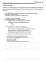
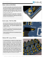
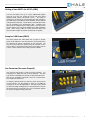
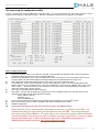
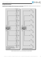
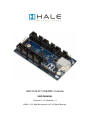
UMC32+M DIY USB-MIDI Controller USER MANUAL Firmware v3.1.0 / Hardware v1.1 ©2008 – 2011 Hale Microsystems LLC, All Rights Reserved. UMC32+ DIY USB-MIDI User Manual Product Description The UMC32+M is an OEM/DIY product that allows Electronic Musicians, Multimedia Artists and Experimenters the ability to create custom user interfaces to control any software application that supports the MIDI protocol. The UMC32+M provides the essential core (microcontroller, power supply, USB-MIDI functionality) to allow the user to easily implement their choice of control elements (example: switches, pots and or faders). The UMC32+M will also translate data from your MIDI host application into logic levels for driving LEDs, Relays and more. Easy to implement with little or no electronics experience. 32 individually configurable inputs or outputs that send or receive user defined MIDI data with any MIDI host application. 64 I/O‟s can be achieved by linking two UMC32+M‟s together using the UMC-Linker board (sold separately). Multiple units can co-exist on the USB bus. Small printed circuit board (1.7” x 3.3”) allows creating portable end devices True plug-and-play (USB-MIDI class compliant drivers are provided by the operating system) Compatible with all versions of Mac OS X, Windows 7 / Vista / XP / 2000 USB bus powered. A single USB cable handles power and data. No programming is necessary (No code to write). Upgradeable firmware via USB using Windows bootloader utility. Using extended MIDI commands, complex MIDI mappings can be realized including: o Individual selection of each I/O‟s corresponding MIDI channel (1 to 16) o Individual selection of each I/O‟s corresponding MIDI message value o Individual selection of each I/O‟s corresponding MIDI message type(s): Note On Poly Pressure Controller Individual selection of each I/O‟s corresponding hardware type including: o Digital Input with pull-up (active low) - For use with SPST tactile switches o Digital Input (active low) - For receiving messages from sensors with active low TTL outputs o Digital Input (active hi) - For receiving messages from sensors with active high TTL outputs o Analog Input - For connection to potentiometers, joysticks, faders etc. o Analog Input (Inverted) - Same as above, except that MIDI data is inverted. o Digital Output (Active High) – For driving LED‟s, Relays, or high power FETs etc. o LED Output with Blink –For blinking of status LED's (see manual for details). The new “plus” version incorporates the following enhancements over original UMC32. o A redesigned PCB with dedicated GND and VCC planes for enhanced signal integrity. o I/O Configuration is now handled entirely by the configuration utility. o Connector for external status LED, on board status LED is now blue. o USB connector is now the standard TYPE B and is much more secure. o Mounting holes (#4 screw) close to USB connector make for a near bulletproof installation. o AUX I/O block for future expansion (TBD) o Improved Firmware Boot loader o Linkable with the original UMC32 o RoHS Compliant (lead Free), manufactured to IPC-A-610 Rev. B, Class II. * Please note that that the new UMC32+M firmware is not compatible with the original UMC32. Before proceeding it is strongly recommended that you read and understand the precautions section of this manual. Please pay attention to the section discussing the safe handling and how to avoid electrostatic discharge (ESD). Failure to observe the recommendations may result in damage to your UMC32+M and void your warranty. Firmware v3.1.0, Hardware v1.1, Datasheet: 09/12/2011 6:15 PM / © 2008-20011 Hale Microsystems LLC, http://www.halemicro.com 2 UMC32+ DIY USB-MIDI User Manual Status Indicator LED (CN11) The indicator LED (LED1) can be found next to the USB connector. This LED provides information about the state of the UMC. When connected, your computer will recognize the UMC and load the class compliant USB-MIDI class device driver that is provided by your operating system. The LED will stay on until communication with your host application begins. At this point the LED will flicker when MIDI traffic between the host application and the UMC occurs. The UMC32+M also provides a 2 pin header + (Anode) and – (Cathode) for connecting to an external LED. It is important to remember that in an addition to the LED itself, you will need to provide a current limiting resistor in series with your LED (Less than 20mA is recommended at 5V dc). Boot Loader / Shift Pin (CN9) When the UMC is plugged into the USB port it first checks the state of the shift pin, if it is pulled low (your switch is being held) then the UMC will enter bootloader mode and prepare to accept a firmware update. See the Windows Bootloader Driver Installation section of this manual for instructions on how upgrade your firmware. In response to customer requests there have been many revisions to the UMC firmware. It is important that you ensure that you are reviewing the correct manual that corresponds with the firmware version of your device. During normal MIDI operation this pin can double the number of software parameters you can control. See Hardware I/O Types For more information. Multiple UMC’s using a USB Hub For connecting more than 1 UMC32+M to the same computer it is recommended that you install one of 8 available firmware binaries on your UMC32+M. First download the latest firmware set from the Hale website. The zip file will contain multiple firmware revisions with “.DLD” extensions. Next download and install the UMC32+M‟s firmware update utility, follow the directions provided by the utility and select the appropriate firmware. Each firmware binary is slightly different in that they contain a unique USB product ID as well as a unique driver name that allows the operating system to identify it on the USB bus. As a rule of thumb it is recommended that when you are configuring your device using the Configuration Utility you dedicate one MIDI channel to each device (2 MIDI channels if you are using the shift feature). As MIDI host applications and operating system do not always load and assign UMCs in the same order this method has proven to be a consistent way of identifying each UMC that is connected to your system. Firmware v3.1.0, Hardware v1.1, Datasheet: 09/12/2011 6:15 PM / © 2008-20011 Hale Microsystems LLC, http://www.halemicro.com 3 UMC32+ DIY USB-MIDI User Manual Linking of two UMC’s for 64 IO’s (CN6) You have the ability to link up to 2 (two) UMC32+Ms together using the 5 pin aux port located at the far end of the board between Bank2 (09-16) and Bank3 (17-24). The linking is achieved by connecting the corresponding pins with jumpers or the “UMC linker” board. Master / Slave operation is auto-detected making the link hassle free. Please keep in mind that slaved units are not accessible to the Configuration utility. Therefore each UMC must be configured prior to being linked. The total current for both devices must not exceed 500mA when utilizing USB bus power. When using a UMC as a slave device the slave must have the CN10 Jumper removed or the slave will not operate. Setup for USB Power(CN10) The factory default has CN10 fitted with a jumper to provide power via the USB bus. This also provides a convenients means for measuring the current consumption of your final build. The only other cases where this jumper should be removed or off is when a UMC is connected to a linker board and is being used as a slave, or when external power is being used as a Master. Aux Connector (An extra 8 inputs!) This connector will provide a means for future expansion. It is configured as a digital input with a 10mS debounce. The input Type is NOT configurable and is fixed as Note On/Off Channel 1, Note # 1 thru 8 if Master, and Notes # 9 thru 16 if a linked slave. The shift pin also works here. If a jumper is placed across Pin1 and Pin3 of the Aux Connector (“A” and Ground - see Pin Diagram on Page 11), the UMC will configure it‟s 32 I/O‟s as Digital Inputs. This test mode is useful tor trouble shooting and diagnosis. It is also important to note that this test mode will not overwrite any of your configuration settings as only the configuration utility will do that. Firmware v3.1.0, Hardware v1.1, Datasheet: 09/12/2011 6:15 PM / © 2008-20011 Hale Microsystems LLC, http://www.halemicro.com 4 UMC32+ DIY USB-MIDI User Manual I/O setup using the configuration utility To begin, download and install the UMC32+M configuration utility. It is recommended that your video display should be set at a minimum screen resolution of 1024x768 or higher). The utility is available for download from the halemicro.com website. How to configure (quick start): 1) 2) 3) 4) 5) 6) 7) 8) 9) 10) Disconnect any wires, ribbon or usb cables from the UMC. Close any MIDI host applications that may be running as the configuration utility needs exclusive access to the UMC‟s MIDI I/O. Reconnect the UMC32+M to your PC with your USB cable. If this is the first time you have connected this device to your computer please wait until Windows displays a message stating that your hardware/devices are ready to use. After windows has installed and loaded the drivers for the device, launch the Configuration Utility. In the “MIDI Ports” section, select the IN Device, and the corresponding OUT device. If you are using Windows XP the UMC32+ will show up as “USB Audio Device”, under Vista and Windows 7 it will show up as “UMC32+_D0x”, where x is the device number. .. The device number you see will depend on the firmware that you have bootloaded into the UMC. All devices are shipped from the factory as D01. Click “Open” to open MIDI input and MIDI output ports. Click “Read”. This will cause the application to grab all of the current configuration data for the selected device into the application. The „Status‟ window should display the following: “Status: UMC32+ read OK” “Firmware: v3.x.x” “Build Date: MM//DD//YY” For each I/O channel select the Hardware I/O type, MIDI Channel, Message Type and message number. When you are finished, click on “Write” to update the UMC with the changes you have made. Exit/Quit the application. Disconnect the USB cable from the UMC, then reconnect it to resume normal MIDI operations. Please exercise care in selecting and connecting any sensors or controls to your UMC. It is recommended that you triple check your wiring to and from the UMC. This is especially the case when using Output Mode(s). It is quite easy to set a channel for output mode and mistake it as an input when connecting your pots or switches causing a short circuit. If you are in doubt about the hardware type of your control please post your compatibility question in the UMC32+M user forums located at http://forums.halemicro.com/. Firmware v3.1.0, Hardware v1.1, Datasheet: 09/12/2011 6:15 PM / © 2008-20011 Hale Microsystems LLC, http://www.halemicro.com 5 UMC32+ DIY USB-MIDI User Manual Configuration utility controls and settings Hardware I/O Types: I/O Disabled – Channel I/O is disabled and will not be processed. All unused channels should use this setting. IN Digital w/pullup (2ms) – Channel is set for Digital (TTL) input with the microcontroller‟s internal pullup enabled. This type is the same digital input mode when using the onboard DIP pack. This type of input is typically used to connect to a single pole single throw switch. One end of the switch connects to ground the other will connect to this I/O channel. This type is also useful for sensors that pull the line low (active low) when the sensor is actuated and release the line or place it in Hi-Z state when the sensor is not actuated. The variations of this input type 2ms, 5ms, 10ms and 20ms denote the debounce delay utilized when the switch is read. Higher values are useful for switches that generate unwanted noise when actuated. IN Digital (Active Low) - Channel is set for Digital (TTL) input. This type is used when accepting a high or low signal from the output of a powered sensor on/off type output. This is for sensors that pull the line low when the sensor is actuated and high when it is not actuated. IN Digital (Active High) - Channel is set for Digital (TTL) input. This type is used when accepting a high or low signal from the output of a powered sensor with a on/off type output. This is for sensors that pull the line high when the sensor is actuated and low when it is not actuated. IN Analog Average - Channel is set for Analog (0v to 5volts) inputs. This is most commonly used for connection to potentiometers, faders and joysticks. It can also accept the input from other sensors that output a voltage in the range of 0 to 5 volts. In this mode, an input of 5 volts will generate a message value of 127 (0x7F hex), whereas an input of 0 volts (gro und) will generate a message value of 0 (0x00 hex). IN Analog Average w/Shift – Same as previous Type IN Analog Average (Inverted) – Same as above however in this mode, an input of 5 volts will generate a message value of 0 (0x00 hex), whereas an input of 0 volts (ground) will generate a message value of 127 (0x7F hex). This mode is especially useful if you happen to solder the +5V and Ground terminals on a potentiometer backwards. Instead of reopening your device to correct the problem by resolder again, simply select this mode instead. IN Analog Average (Inverted) – Same as previous Type IN Analog Direct – This input type reports the raw value of the ADC and does not perform any averaging on the sampled data. This mode is most useful for raw performance and is best used with so force sensing resistors or soft pots. You should expect to see erroneous data from this type of input since filtering is disabled. IN Analog Direct (Inverted) – Same as above however a value of 0 becomes 127, and 127 becomes 0. See above for more information. OUT Digital (Active High) – If a corresponding MIDI message is received by the UMC with a value of 0 then the output for this channel will be low or 0 volts (ground). If the corresponding MIDI message is 127 (0x7F in hexadecimal) then the output will be high or +5volts. OUT LED Blink –This mode functions like the OUT Digital above however, values between 64 and 127 shall turn the LED on values between 1 and 63 shall blink the LED. Zero value turns the LED off. IN Analog Average (MIDI OFF) – This input type is used for internal testing and should not be used. The selected channel is sampled however no data is transmitted. MIDI channel shifting using the BtLdr/Shift pin The configuration utility also provides variants of the above inputs types. These are post fixed as “with Shift”. When a button connected to the shift pin is pressed data is transmitted on the base of the MIDI Channel plus 8. This effectively multiplies the number of software parameters that you can manipulate with your controller. For example a button that ordinarily sends a “Note on, Note #24, on MIDI Channel 1”, when Shifted instead sends “Note on, Note #24, MIDI Channel 9.” For types that are assigned with a base channel of 9 thru 16, those are shifted down. For example a button that ordinarily sends a “Note on, Note #30, on MIDI Channel 10”, when Shifted instead sends “Note on, Note #30, MIDI Channel 2.” MIDI CH Here you can select the desired MIDI Input or output channel that corresponds to the UMC32+M‟s physical hardware I/O channel. Here You can select 1 of 16 channels. When using multiple UMC32s on different ports of a USB hub it is recommended that you assign a MIDI channel to a UMC and stick with it. As it is impossible to guarantee the order which multiple UMC32 will enume rate with Windows a full proof way to consistently identify an assigned I/O is by its MIDI channel. Firmware v3.1.0, Hardware v1.1, Datasheet: 09/12/2011 6:15 PM / © 2008-20011 Hale Microsystems LLC, http://www.halemicro.com 6 UMC32+ DIY USB-MIDI User Manual Message Type Note On (0x90) – This is the recommended message type for input or output controls that are Boolean or ON/OFF. Such controls are switches, or other sensors that output a logic level high or low. When this mode is selected for a channel there are certain conditions that will cause a note off (0x80) message to be generated. Instead of generating a Note On with a velocity of zero the UMC will generate a true note off message. This applies to IN Digital w/Pullup (active low), IN Digital (Active Low), IN Digital (Active High) hardware Input types. For the hardware Output type(s), both note on velocity of 0 as well as Note off velocity zero are interpreted correctly by the UMC. Poly Pressure (0xA0) & Controller (0xB0): These message types are recommended for I/O‟s that are configured as Analog inputs. Msg Num (Message Number) Depending on the Message type the message number may be interpreted differently. The allowable range for this parameter is 0 to 127 (0x00 to 0x7F in hexadecimal). With regards to note on and poly pressure message types these values are indicative of note numbers or keys on a piano keyboard. For instance C-1 is 0, C#4 is 61 and G9 is 127. Default: This will initialize all controls to the following: IN Digital w/pull-up (active low), MIDI Channel X (where X = the device #), Note On, message number 36 thru 67. All Off: This will initialize all controls to the following: I/O Disabled, MIDI Channel X (Where X = the device #), Note On, message number 36 thru 67. Windows Bootloader Driver Installation The UMC32+M is unique in that it allows new firmware revisions are release you can install them in your device by performing a firmware update using the boot loader utility. To continue on and upgrade your firmware, please ensure that your UMC is disconnected from your PC before proceeding. If you have anything connected to the 32 I/O‟s or other connections please remove them prior to initiating a firmware update. Now place the supplied jumper across CN9. Whenever the UMC32+M is attached to your USB port it will check to see if a jumper is placed on CN9. If so, it will enter a special boot loader mode. This bootloader mode requires installing an additional driver so that the PC Bootloader application can perform firmware updates. Download the latest version of the driver and bootloader utility from the halemicro.com website: UMC32+M_USB-MIDI_Bootloader.zip (Bootloader application for Windows) UMC32+M_USB-MIDI_Bootloader_Drivers.zip (Bootloader drivers) UMC32+M_USB-MIDI_DLD.zip (Firmware binary to upgrade UMC) Save and extract the ZIP file to a new folder on your desktop. At this point you can re-connect the USB cable to your UMC. In the lower right corner of your screen Windows will report “Installing device driver software”. After a few moments Windows will display a message stating “Device driver software was not successfully installed”. This message is expected. Go to your Start menu, click on Control Panel, click on Hardware and Sound and open Device manager. Double click On “Other devices” and double click on “UMC32+M BootLdrUSBFSe_1.x” to bring up properties. Click on “Update Driver” and select “Browse my computer for driver software.” Click the Browse button and find the “UMC32+M_USB-MIDI_Bootloader_Drivers” folder on your desktop. Windows will show a message stating “Installing driver software” followed by a Security message. Verify that Hale Microsystems LLC is the publisher and click the install button. You should see “Windows has successfully installed your driver software”, click Close. Click close for properties as well. Back in the Device Manager under “Universal Serial Bus controllers” you should see “UMC32+M USB-MIDI Bootloader Driver (3.4.6.000)”. Now that your driver is installed you can launch the Bootloader utility “UMC32+M_USB-MIDI_Bootloader_v1_x”. If you get an error when launching the application check and make sure that “CyUSB.dll” is in the same directory as the app. Once the application has loaded you should see a message at the bottom of the app indicating that the driver has been detected. Now click on select DLD file to download. You should see the “Downloading….” Message, then after a minute or so a popup dialog will display “Downloa d complete. You many now disconnect the USB cable from your UMC and remove the jumper on CN9.” Click OK, then disconnect the USB cable from the UMC, and remove CN9. The firmware update is complete. Firmware v3.1.0, Hardware v1.1, Datasheet: 09/12/2011 6:15 PM / © 2008-20011 Hale Microsystems LLC, http://www.halemicro.com 7 UMC32+ DIY USB-MIDI User Manual General Precautions The UMC is designed to protect against short circuits, over current conditions, transient voltages and electrostatic discharge. However, we ask that you observe some simple guidelines when working with the UMC. Failure to do so may cause damage to your equipmen t and/or void your product warranty. o Treat the UMC32 as you would any modern computer RAM and observe best practices for Electrostatic Discharge see: http://www.phys.cwru.edu/courses/p203/resources/ESDprocedure.pdf or http://www.esda.org/esd_fundamentals.html o Do not place a jumper across the ExtLED or Ext 5V Power pins, otherwise it will cause a short circuit o Do not solder any wires or attempt to make any modifications to the UMC directly. o Do not connect the “+V” (+5 Volts DC) terminal to G (Ground). When this occurs, it is commonly referred to as a “short circuit”. o Always unplug the USB cable from the device before modifying connections on the UMC. o As with all electronic devices, observe proper ESD handling practices. Always handle the printed circuit board (PCB) by the edges. Never touch the top or bottom of the PCB. o Never allow the UMC to touch a wet or conductive surface. o Do not use any external voltage source to power devices that are connected to the UMC. o The maximum recommended current per channel is 8mA. o You may use the +5V and Ground pins off each bank to power other devices such as LED‟s however the maximum recommended is 80mA. o As an additional precaution, we strongly recommend using a powered USB hub when experimenting with the device. Once you have finalized your project, and are sure you do not have any short circuits, then you may connect the UMC directly to your computer‟s USB input. This is especially important when interfacing with a laptop, as damage to your laptop could be substantial. o This product is offered to the end user in a non-enclosed OEM form. It is the responsibility of the end user of this product to ensure that they comply with local regulations pertaining to unintentional radio frequency emissions. In the United States, this pertains to FCC rules and regulations, Part 15, Section B. Firmware v3.1.0, Hardware v1.1, Datasheet: 09/12/2011 6:15 PM / © 2008-20011 Hale Microsystems LLC, http://www.halemicro.com 8 UMC32+ DIY USB-MIDI User Manual Example Connections Although there are a seemingly infinite number of types of control elements (potentiometers, switches etc.) that you can connect to the UMC, here are a few examples of how to connect the most common types. * Please note that connection to +5V is not necessary for any SPST switch. Firmware v3.1.0, Hardware v1.1, Datasheet: 09/12/2011 6:15 PM / © 2008-20011 Hale Microsystems LLC, http://www.halemicro.com 9 UMC32+ DIY USB-MIDI User Manual UMC32+M I/O Pin Diagram UMC32+M with ribbon cables attached Ribbon cable kit sold separately (Part # RIB50) Firmware v3.1.0, Hardware v1.1, Datasheet: 09/12/2011 6:15 PM / © 2008-20011 Hale Microsystems LLC, http://www.halemicro.com 10 UMC32+ DIY USB-MIDI User Manual Two (2) UMC32+M’s with 10 EXP8SC screw terminal boards for 64 channel inputs plus an additional 16 switches on the Aux inputs (8 from master, 8 from slave). This provides a total of 80 controls using a single bus powered USB connector. Linker board (in center) connects the UMC’s together. Using multiple processors (a dedicated processor for every 32 I/O’s and 8 aux inputs) the UMC can achieve a scan rate that is 2X faster than a single processor. It should be noted that the UMC that is connected to the USB bus is the Master, while the linked UMC is the slave. Firmware v3.1.0, Hardware v1.1, Datasheet: 09/12/2011 6:15 PM / © 2008-20011 Hale Microsystems LLC, http://www.halemicro.com 11 UMC32+ DIY USB-MIDI User Manual Mechanical Specifications UMC32+M dimensions (inches): The three 0.22” mounting holes for the UMC32+M are for #4 screws USB Connector measurments (millimeters): Electrical Specifications Exceeding the absolute maximum ratings below may cause permanent damage to the device. Storage temperature: -20ºC to + 70ºC Operating temperature: 0ºC to + 50ºC Operating voltage (power supplied via USB bus): 5.1 Volts DC max Max recommended current per I/O channel 8mA Maximum device current: *500mA USB Bus Powered, 2A external. Firmware v3.1.0, Hardware v1.1, Datasheet: 09/12/2011 6:15 PM / © 2008-20011 Hale Microsystems LLC, http://www.halemicro.com 12 UMC32+ DIY USB-MIDI User Manual Limited Warranty Hale Microsystems LLC warrants this product to be free of manufacturing defects for a period of 90 days (USA only). If you feel that there is a defect with your device, please email technical support with a detailed description of the problem: [email protected]. In most cases we will simply issue a replacement. It is the responsibility of the customer to cover the cost of shipping to and from Hale Micro. Devices shall only be accepted in original factory packaging. We will not accept the return of any product that has been modified beyond factory condition. Any attempt to modify your unit shall void this warranty. Disclaimer Neither the whole nor any part of the information contained herein or the product described in this datasheet may be adapted or reproduced in any material or electronic form without the prior written consent of Hale Microsystems. This product and its documentation are supplied on an as-is basis, and no warranty as to their suitability for any particular purpose is either made or implied. Hale Microsystems LLC will not accept any claim for damages whatsoever arising as a result of use or failure of this product. Your statutory rights are not affected. This product is not intended for use in any medical appliance, device or system in which the failure of the product might reasonably be expected to result in personal injury. This document provides preliminary information that may be subject to change without notice. Windows is a registered trademark of Microsoft Corporation in the United States and other countries. Firmware v3.1.0, Hardware v1.1, Datasheet: 09/12/2011 6:15 PM / © 2008-20011 Hale Microsystems LLC, http://www.halemicro.com 13