1
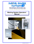
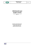
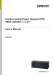
Operating Instructions INSIGHT GENIUS DATA MANAGEMENT 9 – 18812 96th Ave Surrey, BC Canada, V4N 3R1 Tel: (001) 604 607-6028 Fax: (001) 604 607-6026 e-mail: [email protected] 1 TecTronix-INSIGHT-GENIUS.doc Customer Name: Location: Date in Service d/m/y: We would like to take this opportunity to thank you for purchasing your Metal Detector from Tectronix. The confidence you have placed in our product is sincerely appreciated and we will endeavor to provide the best service and support possible. Please take the time to read the User Manual completely as this provides you with the expertise necessary to install and adjust the system according to your requirements. In addition to this, you will learn about the sophisticated options provided by the Genius electronics. If you have any problems in the set up and operation of your system, the Tectronix team are available to assist you. Tectronix Systems inc. 9 – 18812 96th Ave. Surrey, British Columbia Canada, V4N 3R1 Telephone: (001) 604 607-6028 Fax: (001) 604 607-6026 E-mail: [email protected] 2 TecTronix-INSIGHT-GENIUS.doc Contents Contents 1 Introduction 4 2 System requirements 5 3 Installation 6 4 Installation instructions 7 4.1 Interface card 7 4.2 Cabling 7 4.3 Serial data format (RS232 and RS485) 7 4.4 Instruction for the installation of the serial interface board (Option) 8 4.5 Software installation 9 4.6 Starting the INSIGHT GENIUS software package 9 5 6 Instruction manual 10 5.1 General 10 5.2 General overview 11 5.3 Main display 5.3.1 Task strip 5.3.2 Change of product number and product name 5.3.3 Change of parameters 5.3.4 Data transfer interrupt and restorage 5.3.5 Alarm and error messages 5.3.6 Bar graph display 5.3.7 Quitting the program 11 12 13 13 14 15 16 16 5.4 Setup window 17 5.5 Service display 18 5.6 Product parameter window 20 5.7 Date / Time window 22 5.8 Password window 22 5.9 Test interval window 23 5.10 Product teaching 24 5.11 Log book menu 27 5.12 Online diagram 29 5.13 Metal diagram 30 5.14 Diagram feature 31 Address 32 3 TecTronix-INSIGHT-GENIUS.doc 1. Introduction 1 Introduction The HACCP standard is an important part of the quality management in the food processing industry. Tectronix Metal Detectors of the series GENIUS provide thanks to the sophisticated state of the art electronics beside the extreme ease of operation all relevant HACCP informations. The storage of all parameters, metal, error and alarm status signals provided with date and time (log book) allows a comfortable evaluation and interpretation of sources of metal impurities. Furthermore all functions are integrated that are necessary to meet the HACCP standards which includes the examination and filling of device and process datas. The Central Data Management INSIGHT GENIUS provides well arranged displayed and recorded datas. Additionally remote assistance by the Tectronix customs service support can be provided by a modem or ISDN-board. Features at a glance: • Central and ease of operation of Tectronix Metal Detectors and Separators by a single PC • Clearly arranged display of all installed Tectronix devices and processing equipment • Central changing of device parameters in case of product and batch change • Central recording, logging and evaluation of events of all connected Tectronix units (parameter changings, alarm, metal and error messages) • Easy integration of the stored datas into the management system INSIGHT GENIUS • Simple and fast analysis of metal impurity sources • Reduction of machine down time and maintenance costs by means of remote service support capability 4 TecTronix-INSIGHT-GENIUS.doc 2. System requirements 2 System requirements The Central Data Management System INSIGHT GENIUS allows to connect up to 10 (optional 40) Tectronix Metal Detectors and Separators equipped with the GENIUS control unit. Systems requirements: • Pentium Processor 233 MHz min. • RAM 32 MB (pref. 64 MB) • Screen resolution 1024 x 768 • RS 485 Interface board with automatic TxD / RxD control • Recommended Interface board: MOXA Industio CP 132 (optional) • 15" -monitor (pref. 17") The data communication is handled by Tectronix interface protocol. Remote service support can be operated by a modem or ISDN-board. 5 TecTronix-INSIGHT-GENIUS.doc 3. Example installation 3 Installation The picture below shows an example for an integrated metal detector and separator control system using the Central Data Management System INSIGHT GENIUS. The communication is carried out by a simple shielded two wire cable using the RS 485 interface standard. 6 TecTronix-INSIGHT-GENIUS.doc 4. Instructions 4 Installation instructions 4.1 Interface card The INSIGHT GENIUS software requires an RS 485 interface card. Tectronix recommends the MOXA Industio CP 132, which can be delivered on request. However any other interface card can be used which provides an automatic RxD / TxD control. 4.2 Cabling The connection cabling has to be carried out by a shielded two-wire line which can also be supplied on request. It has to be connected according to the diagram. The wiring diagram relates to the recommended interface card Industio CP 132. If a different card is used consider different pinning of the Sub-D connector (see operating manual Control Unit GENIUS Optional: serial interface”). S S S S 2 1 2 3 1 3 4 Female connector Sub-D 9-pin for RS485 of Industio CP 132 (back view) GENIUS m 4 sw rt sw GENIUS 1 rt GENIUS 2 5 S 4 9 rt GENIUS 3 S rt sw 2 = a = rt 1 = b = sw Twisted pair shielded cable (Article No. 08025320) GENIUS n S S 1 6 2 7 3 8 sw S 2 1 2 3 1 4 sw 3 4 rt sw rt Male connector type Hirschmann ELST 4012 PG9 (Article No. 08021325) back view 4.3 Serial data format (RS232 and RS485) 19200 Baud 8 Data bits 1 Stop bit no parity The INSIGHT GENIUS requires a baud rate to be set on the electronics board to 19200 Baud. 7 TecTronix-INSIGHT-GENIUS.doc 4. Instructions 4.4 Instruction for the installation of the serial interface board (Option) The serial interface board Industio CP 132, supplied by MOXA, is used for the integration of the metal detector into the data management system. It provides two additional serial interfaces, one RS 422 and one RS 485. The data management system requires the RS 485 mode. To install the board follow the instruction: 1. Disconnect the PC from the mains supply! 2. Remove the PC cover 3. Set the switches and jumpers according to the picture below: JP 1 set SW 1 SW 2 1 1 ON OFF COM 3 2 2 all switches ON JP 2 set COM 4 JP 1 and 2 set the load resistors for both ports. SW 1 sets the automatic data direction control for both ports. SW 2 sets both ports to RS 485 mode. 4. Insert the board to a free PCI slot and close the PC with the cover. Use the installation instruction of the board supplier. All relevant steps are described in a comprehensive form. 8 TecTronix-INSIGHT-GENIUS.doc 4. Instructions 4.5 Software installation Insert the disk or CD-Rom and open the file “install.exe”. You will get an installation menu which indicates the recommended installation path (Unzip-listing). Activate the “Unzip” button with the mouse which installes the software with the path “C:\CDM”. Close the installation routine by pressing the “Close” button. 4.6 Starting the INSIGHT GENIUS software package Call the Explorer and change to above stated directory. Start then the file MSG_Visu.exe. 9 TecTronix-INSIGHT-GENIUS.doc 5. Instruction manual 5 Instruction manual 5.1 General The Central Data Management INSIGHT GENIUS allows to display, log and print out: • Product data (product name and parameters) • Service and setup data • Metal alarms • Log book data including device and product statistics The exact meaning of the datas are explained in the instruction manual of metal detector GENIUS. The program consists of several menus or program windows: • General overview. This window is opened at the program start and displays product number, product name, device name and device status. • Main menu. Device parameters, metal signals and the buttons to call the remaining menus. • Device parameters are displayed in service, setup and product data menu. • Log book allows the polling, printing and storage of all historic recorded events. • Online metal signal diagram displays the current analog metal signals. • Signal diagram records the maximum value of metal signals within 24 hours. At the program start the main menu and the signal diagram are opened automatically. The remaining menu can be opened and closed by using the buttons at any time. 10 TecTronix-INSIGHT-GENIUS.doc 5. Instruction manual 5.2 General overview The main menu contains all important informations of the individual devices. By double clicking on the desired device, the main menu is closed and the main display for the selected device is opened (see 5.3, 5.8 and 5.9). 5.3 Main display Tabulator strip for the change between the individual devices Display of the device parameters Button for restoration of the data transfer between PC and Control unit Display for data transfer interruption between PC and Control unit. In this situation the button "Connection restore" has to be operated 11 TecTronix-INSIGHT-GENIUS.doc 5. Instruction manual Display for alarm- and error messages of the Control unit Task strip with different programs Button for parameter changing. Clicking this button allows to change the parameters. Clicking a second time causes a transfer and change of the parameters at the addressed metal detector Control unit. 5.3.1 Task strip The task strip allows four different selections: • General overview display an overview of all connected devices (see chapter 5.2) • Log book see chapter 5.11 • Setup eight submenus can be selected - Setup menu (chapter 5.4) - Service menu (chapter 5.5) - Product data (chapter 5.6) - Date and time (chapter 5.7) - Diagram adjustments (chapter 5.14) - Test interval (chapter 5.9) - Password (chapter 5.8) - Product teaching (chapter 5.10) The menu topics date / time, test interval and product teaching are secured by a password. Essential functions could be erased. • Quit (escape) 12 TecTronix-INSIGHT-GENIUS.doc 5. Instruction manual 5.3.2 Change of product number and product name The button “Change product” allows to change product number and product name of a current product. After pressing the button the input fields turn to yellow and the product number and name can be changed. The new datas are set when escaping the input field or pressing the ENTER button. 5.3.3 Change of parameters The parameters displayed in the main menu can be changed by pressing the button “change parameter” which enables the input. After a parameter change press the button “Send parameter” to transfer the new data to the corresponding device. After pressing “Change parameter” the bottom line will display the limits within the corresponding parameter can be adjusted. 13 TecTronix-INSIGHT-GENIUS.doc 5. Instruction manual 5.3.4 Data transfer interrupt and restorage In case of interruption between the PC and the metal detector control unit the message “Connection interrupted” is displayed. The button “Restore connection” allows to restore the connection to the device. Besides this, the program tries every 30 sec to restore the connection automatically. A successful restorage of the connection will change to the main menu. 14 TecTronix-INSIGHT-GENIUS.doc 5. Instruction manual 5.3.5 Alarm and error messages As soon as an alarm or error message is sent from a metal detector control unit it will be displayed on the screen in a red field. It remains displayed until the problem is fixed or reset. Eight different alarm and error messages exist and are displayed with an additional message box showing the faulty device, date and time. Alarm/error message in INSIGHT GENIUS Signification Autobalance active balance Automatic balance of the detector head due to extrem changements in the surroundings is activated The automatic balance control is out of range Receiver too high Receiver too low Transmitter or receiver faulty Output overloaded Proximity switch faulty Battery low Control unit or connection cable between detector head and pc board AWE faulty Short circuit at the magnetic valve or cable Proximity switches, scanning the belt speed, are faulty Battery on the control board is discharged 15 TecTronix-INSIGHT-GENIUS.doc 5. Instruction manual 5.3.6 Bar graph display A bar graph display shows the analog signal (amplitude) of the metal detector. As long as the bar is in blue colour no metal alarm is triggered. When the bar turns to red a metal pulse is generated. Normal status, signal amplitude below threshold Metal detection, threshold exceeded 5.3.7 Quitting the program To quit the INSIGHT GENIUS program press the “Quit” button. The application will be closed and the connection to the metal detection control units are interrupted. A certainty inquiry whether the program wants to be exited appears. 16 TecTronix-INSIGHT-GENIUS.doc 5. Instruction manual 5.4 Setup window 1 2 3 4 5 6 7 8 9 10 The Setup window provides information about software version, balance condition of the detector head and operating frequency. This information is not changeable. Version no of the software of the controller board Version no of the software of the evaluation board Board version of the controller Receiver voltage in Volts Operating frequency of the metal detector in kHz Alternative frequency of the coil in kHz 17 TecTronix-INSIGHT-GENIUS.doc 5. Instruction manual Frequency divergence in percentage Negative boundary in percentage Positive boundary in percentage Number of the used detection coil The indicated values are - besides the alignment - invariable values and can only be used for information. Detailed information which includes the significance of each single value can be found in „GENIUS“ operating manual volume 2 5.5 Service display The service menu provides information about the current operating modes and characteristics. In dependence on your appliance type either the right or the left window appears. Product conveying modes Conv. Conveyor mode (product is conveyed by belt conveyor) Consens Conveyor belt and belt control system (left window) FF Free fall or gravity fall, e.g. Rapid xxxx (right window) SC/PC Vacuum or pressure conveying lines (right window) Time delay or distance measurement Used to control an eject unit after metal detection 18 TecTronix-INSIGHT-GENIUS.doc 5. Instruction manual Time delay used with conveyors running at a constant speed. The conveying speed is indicated in m/s. Distance used with conveyors which can run of a varying conveying speed. The signals of proximity switches are used to get the set distance. Light barrier This field indicates if a light barrier is used in order to determine the exact position of a contaminated product for exact and reliable rejection. non Metal signal not synchronized with photoelectric barrier LS synchrony Metal signal synchronized with photoelectric barrier inverse detection A metal signal is created for products not containing any metal impurity. Ejection monitoring Indicates whether the control waits for a revertive signal or not after the splitting. Full indicator Indicates an alarm when the reject container is full. Dimensional unit Indicates the dimension of the conveyor speed Meter per second Speed in m/s. Meter per minute Speed in meter per minutes. Flap monitoring Indicates whether the ejection flap is in correct position or not (i.e. operative). Quickflap Pneumatic cylinder monitor. In each case it needs a signal for release and a signal for reset. 19 TecTronix-INSIGHT-GENIUS.doc 5. Instruction manual 5.6 Product parameter window This window shows information about metal detection modes and the most important parameter, which is the processing speed of a product. Output for magnetic valve High active or Low active The output is set to 24V at the High active mode when a metal alarm its set. The Low active mode sets the output to 0V in case of metal detection. Metal in case of failure If YES is set, the metal alarm output is also set in case of system failure. Direction of ejection: one way or two ways One way setting: A pusher is activated by metal detection and resets to the starting position after the ejection period. Two way setting: A pusher is activated by metal detection and stays in its current position after the ejection period. 20 TecTronix-INSIGHT-GENIUS.doc 5. Instruction manual Tracking The tracking function can be activated (On) or not (Off). It is used to compensate small changings of product characteristics or of the surrounding automatically to obtain optimum sensitivity. Quicklearn Activated if input is On. Used if a change of products should be detected and adjusted automatically. This feature however requires sufficient space between detector and eject unit, i.e. at least three times of the product length. If an extreme change of the current product characteristic is detected, a metal alarm is set. If the following product has the same characteristic the parameters are adjusted automatically to the product and checked a third time. The metal alarm is reset before the first product reaches the eject unit. Half wave Activated when set to On. Used mainly with intermittent operation (stop and go) to provide optimum detection capabilities. This so called halfwave metal detection mode is more sensitive to interferences than the standard mode which is active when set to Off Conveying speed The field displays the current set conveying speed. It should correspond to the actual speed of conveyor unit. 21 TecTronix-INSIGHT-GENIUS.doc 5. Instruction manual 5.7 Date / Time window By activation of this window, date and time setting of the electronic unit are shown. To change the value push the „change“ button. To send the changed value to the appliance push the „send“ button. This window is secured by a password. 5.8 Password window The password locks the functions and can be changed in window. The function change of product and parameter changes for example are secured by this password. 22 TecTronix-INSIGHT-GENIUS.doc 5. Instruction manual 5.9 Test interval window The test interval, which verifies the operability, can be set by the visibility. Only the appliance which is active on the main screen can be adjusted. By activation the window actual shows the settings of the appliance. The menu alarm interval provides the following settings: no alarm hourly daily weekly Depending on the settings your choose, a varying number of settings can be chosen in the following menu topics. 23 TecTronix-INSIGHT-GENIUS.doc 5. Instruction manual Described as following: no alarm: No further settings can be made. The transmission of the settings to the appliance cuts the alarm function off. hourly: The setting of the weekday and time can be deactivated in this mode. Every hour the alarm triggers independently of the time and the weekday. daily: The time is additionally activated in this section. With this settings the test forward transfer signal is delivered to exactly this time, which is set in the time field. The „Weekday“ field is still deactivated. Test object: Additional comments have to be made for the following three fields. Up to three test objects can be set. Therefore the numbers 0 to 99 are used. Hereby the 0 means no test object. A test object has to be set, hence, the first field can be set from 1 to 99. The other two test objects are optional. If 0, no test object is selected for the second test object the third can only be 0. Hence, the field is deactivated and set to 0. 5.10 Product teaching The menu product teaching allows to start the product teaching procedure with a current running product. Important: Is the learning process started on base of the visualization it has also be completed by the visualization. In case of remote teaching a direct appliance operation is not possible, because of indefinite conditions. The reason therefore is, that the visualization always has to know the actual conditions of the appliance. Thereby the conditions are extracted after each step. If all in a sudden work is continued directly at the appliance, no information divulged to the visualization and it operates in its previous conditions. 24 TecTronix-INSIGHT-GENIUS.doc 5. Instruction manual Procedure: The device has to run in the operating mask, so that the teaching procedure can be started. Otherwide the following window appears: First step of teach in procedure: At first the F4 button appears in gray colour. It can only be pushed when the lettering turns to black. Second step: The following message appears: The actual teaching cycle appears in the lower left corner. This step is repeated a several times (max. 15 times) with products having an extremely high product effect. Afterwards an error message appears and the process is broken off. 25 TecTronix-INSIGHT-GENIUS.doc 5. Instruction manual The message can also appear earlier, if the product effect in general is too high. Third step: In case of successful teach in procedure the following message appears: To get back to the main menu, confirm this message. 26 TecTronix-INSIGHT-GENIUS.doc 5. Instruction manual 5.11 Log book menu The log book menu allows to poll all records. Each button represents a corresponding listing shown on the picture below. For more information see the operating manual for the GENIUS Control unit. 27 TecTronix-INSIGHT-GENIUS.doc 5. Instruction manual Print The Print button opens the printing menu for the current record. Save The Save button stores the current record as a text file on the hard disk. The listing of the record files can be set and read by the inifile “Setup ini” with the key (directory). The data is stored with date, time and device identification: Structure: Year, month, day, device id (i.e. 990601M.txt) 99 year 06 month 01 day M device id The datas can be processed with any editor or even with Excel. Close The Close button closes the displayed windows. Display Display field for the recorded datas. Scroll bar for long records. 28 TecTronix-INSIGHT-GENIUS.doc 5. Instruction manual 5.12 Online diagram The online diagram displays and records the metal signal of the last 10 minutes in steps of 1 second. This diagram eases a diagnosis in case of failure. red bar metal detection represents the threshold. Signal amplitudes exceeding the threshold trigger a metal alarm. blue bar signal noise 29 TecTronix-INSIGHT-GENIUS.doc 5. Instruction manual 5.13 Metal diagram The metal diagram records the amplitudes of the metal signal of the last 4 hours in steps of 1 min. Each recording represents the maximum amplitude within the 1 min. period. The diagram has a time capacity of 24 hours. After this period the recording starts at the beginning by overwriting the old datas red bar metal detection threshold. Exceeding signals causes a metal alarm. blue bar signal noise 30 TecTronix-INSIGHT-GENIUS.doc 5. Instruction manual 5.14 Diagram feature The window diagram features allows to change time axis as well as the metal signal axis. The button “Treshold” zooms the metal signal axis in reference to the threshold which gives more detailed information about the noise conditions or product signal characteristic. To get back press the button again. The lower arrow buttons are able to shift the diagrams. The time axis skips 4 hours to the left or the right side if the button is pushed once. With this view the user is able to look at the daily progression precisely. To go back to the actual curve, close the window. 31 TecTronix-INSIGHT-GENIUS.doc 6. Address 6 Address Manufacturer’s Tectronix Systems inc. 9 – 18812 96th Ave Surrey, British Columbia Canada, V4N 3R1 Telephone: (001) 604 607-6028 Fax: (001) 604 607-6026 E-mail: [email protected] Representative: 32 TecTronix-INSIGHT-GENIUS.doc