1
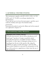
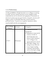
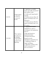
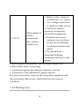
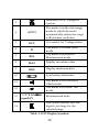
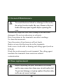
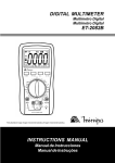
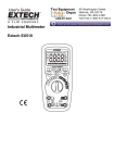
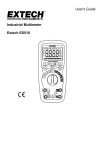
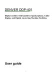
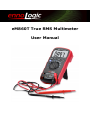
eM860T True RMS Multimeter
User Manual
Version 1.4. Revised 3/19/2015.
© 2015 ennoLogic™. All rights reserved.
http://ennologic.com
TABLE OF CONTENTS
1. GENERAL INSTRUCTIONS ................................................. 1
1.1 Precautionary Safety Measures .......................................... 1
1.1.1 Preliminary............................................................... 2
1.1.2 During Use ............................................................... 4
1.2 Battery Installation or Replacement ................................... 7
1.3 Symbols ............................................................................... 9
1.4 Instructions ......................................................................... 9
2. INSTRUMENT DESCRIPTION ........................................... 11
2.1 Main User Elements .......................................................... 11
2.2 LCD Display ....................................................................... 13
2.3 Keypad .............................................................................. 15
2.3.1 SELECT ................................................................... 15
2.3.2 HOLD/BACKLIGHT............................................. 15
2.3.3 RANGE ................................................................... 15
2.3.4 REL△ ....................................................................... 16
2.3.5 Hz % ........................................................................ 16
2.3.6 MAX/MIN .............................................................. 16
3. FUNCTION DESCRIPTION ................................................ 17
3.1 General Functions ............................................................. 17
3.1.1 DATA HOLD mode .............................................. 17
3.1.2 Manual ranging and Autorange mode............... 17
3.1.3 Battery Saver .......................................................... 18
3.1.4 Relative Measurement Mode ............................... 19
3.1.5 TRUE RMS Measurement .................................... 19
3.2 Measurement Functions ................................................... 20
3.2.1 AC and DC Voltage measurement ..................... 20
3.2.2 Resistance Measurement ...................................... 23
3.2.3 Capacitance Measurement ................................... 26
3.2.4 Continuity Check .................................................. 28
3.2.5 Diode Test .............................................................. 31
3.2.6 Frequency and Duty Cycle Measurement ......... 34
3.2.7 Temperature Measurement ................................. 35
3.2.8 Current Measurement .......................................... 36
3.2.9 NCV (Non-Contact Voltage Detect) ................... 38
4. TECHNICAL SPECIFICATIONS ........................................ 39
4.1 General specifications ....................................................... 39
4.2 Measurement Specifications ............................................ 40
4.2.1 Voltage .................................................................... 40
4.2.2 Frequency ............................................................... 42
4.2.3 Resistance ............................................................... 42
4.2.4 Diode Test .............................................................. 43
4.2.5 Continuity Check .................................................. 43
4.2.6 Capacitance ............................................................ 43
4.2.7 Temperature ........................................................... 44
4.2.8 Current.................................................................... 44
5. MAINTENANCE .................................................................. 45
5.1 General Maintenance ....................................................... 46
5.2 Fuse replacement ............................................................. 46
6. ACCESSORIES ....................................................................... 47
1. GENERAL INSTRUCTIONS
This instrument complies with IEC 61010-1: 2001, CAT Ⅲ
1000V and CAT Ⅵ 600V overvoltage standards. See
Specifications.
To get the best service from this instrument, read this user's
manual carefully and respect the detailed safety
precautions.
International symbols used on the Meter and in this manual
are explained in chapter 1.2.
1.1 Precautionary Safety Measures
Important Note: Limited Liability
Cascadia Innovations is the exclusive distributor of all
ennoLogic™ products. Except as explicitly stated,
Cascadia Innovations is not liable for direct, indirect,
incidental, or other types of damages arising out of, or
resulting from the use of this product. By using the
eM860T you agree to hold ennoLogic™ and Cascadia
Innovations harmless for any and all consequences of the
use of this product or application of data from the use of
this instrument.
1
1.1.1 Preliminary
As the possibilities of high transient over-voltages occurring
in today’s power systems increase, more stringent safety
standards are set for electrical test equipment. Transients on
electrical systems (power grid, feeder or branch circuits) will
trigger a series of incidents that may result in serious
personal injury. To protect you against transients, safety
must be built into the test equipment.
Overvoltage
category
CAT I
In brief
Examples
Electronic
• Protected electronic
equipment.
• Equipment connected to
(source) circuits in
which measures are
taken to limit transient
over-voltages to an
appropriately low level.
• Any high-voltage, lowenergy source derived
from a high winding
resistance transformer,
such as the high-voltage
section of a copier.
2
CAT II
CAT III
Single-phase
receptacle
connected
loads
Three-phase
distribution,
including
single-phase
commercial
lighting
3
• Appliance, portable
tools, and other household
and similar loads.
• Outlet and long branch
circuits.
• Outlets at more than 10
meters (30 feet) from CAT
III source.
• Outlets at more that 20
meters (60 feet) from CAT
IV source.
• Equipment in fixed
installations, such as
switchgear and polyphase
motors.
• Bus and feeder in
industrial plants.
• Feeders and short
branch circuits,
distribution panel devices.
• Lighting systems in
larger buildings.
• Appliance outlets with
short connections to
service entrance.
CAT VI
Three-phase at
utility
connection,
any outdoor
conductors
• Refers to the “origin of
installation”; i.e., where
low-voltage connection
is made to utility power.
• Electricity meters,
primary overcurrent
protection equipment.
• Outside and service
entrance, service drop
from pole to building,
run between meter and
panel.
• Overhead line to
detached building,
underground line to well
pump.
When using this Multimeter, the user must observe all
normal safety rules concerning:
• protection against the dangers of electric current.
• protection of the Multimeter against misuse.
For your own safety, only use the test probes supplied with
the instrument. Before use, check that they are in good
condition.
1.1.2 During Use
4
• If the meter is used near noise generating equipment, be
aware that display may become unstable or indicate large
errors.
• Do not use the meter or test leads if they look damaged.
• Use the meter only as specified in this manual; otherwise,
the protection provided by the meter may be impaired.
• Use extreme caution when working around bare
conductors or bus bars.
• Do not operate the meter around explosive gas, vapor, or
dust.
• Verify a Meter's operation by measuring a known
voltage. Do not use the Meter if it operates abnormally.
Protection may be impaired. When in doubt, have the
Meter serviced.
• Use the proper terminals, function, and range for your
measurements.
• When the range of the value to be measured is unknown,
check that the range initially set on the multimeter is the
highest possible or, wherever possible, choose the
autoranging mode.
• To avoid damage to the instrument, do not exceed the
maximum limits of the input values shown in the
technical specification tables.
• When the multimeter is linked to measurement circuits,
do not touch unused terminals.
• Caution when working with voltages above 60Vdc or 30V
AC rms. Such voltages pose a shock hazard.
5
• When using the probes, keep your fingers behind the
finger guards.
• When making connections, connect the common test lead
before connecting the live test lead; when disconnecting,
disconnect the live test lead before disconnecting the
common test lead.
• Before changing functions, disconnect the test leads from
the circuit under test.
• For all DC functions, including manual or auto-ranging,
to avoid the risk of shock due to possible improper
reading, verify the presence of any AC voltages by first
using the AC function. Then select a DC voltage range
equal to or greater than the AC range.
• Disconnect circuit power and discharge all high-voltage
capacitors before testing resistance, continuity, diodes, or
capacitance.
• Never perform resistance or continuity measurements on
live circuits.
• Before measuring current, check the meter's fuse and turn
off power to the circuit before connecting the meter to
• the circuit.
• In TV repair work, or when carrying out measurements
on power switching circuits, remember that high
amplitude voltage pulses at the test points can damage
the multimeter. Use of a TV filter will attenuate any such
pulses.
6
• Use just one 6F22 battery, properly installed in the
Meter's battery case, to power the Meter.
• Replace the battery as soon as the battery indicator
(
) appears. A low battery might produce false
readings that can lead to electric shock and personal
injury.
• Do not measure voltages above 1000V in Category III, or
600V in Category Ⅳ installations.
• When in REL mode, the “REL” symbol is displayed.
Caution must be used because hazardous voltage may be
present.
• Do not operate the Meter with the case (or part of the
case) removed.
1.2 Battery Installation or Replacement
To avoid false readings, which could lead to
possible electric shock or personal injury, replace
the battery as soon as the battery indicator
(
) appears.
Before installing or replacing the battery,
disconnect test leads and/or any connectors from
any circuit under test, turn the meter off and remove
test leads from the input terminals.
7
1. Set rotary switch to the OFF position.
2. Disconnect test leads and/or any connectors from the
terminals.
3. Remove the red protective rubber casing by carefully
peeling it away from the black plastic enclosure.
4. Use a screwdriver to unscrew the two screws on the
5.
6.
7.
8.
9.
battery cover, on the back of the unit near the bottom.
Remove the battery cover from the meter.
If you are replacing the battery: remove the used battery
Install a new 9V battery (6F22).
Replace the battery cover and tighten the screws.
Attach protective rubber casing.
8
1.3 Symbols
Symbols used in this manual and on the instrument:
Caution: refer to the instruction manual.
Incorrect use may result in damage to the device
or its components.
~
AC (Alternating Current)
DC (Direct Current)
AC or DC
Earth ground
Double insulated
Fuse
Conforms to European Union directives
1.4 Instructions
• Remove test leads from the Meter before opening the
Meter case or battery cover.
• When servicing the Meter, use only specified replacement
parts.
• Before opening up the instrument, always disconnect
from all sources of electric current and make sure you are
9
•
•
•
•
•
not charged with static electricity, which may destroy
internal components.
Any adjustment, maintenance or repair work carried out
on the meter while it is live should be carried out only by
appropriately qualified personnel, after having taken into
account the instructions in this manual.
A "qualified person" is someone who is familiar with the
installation, construction and operation of the equipment
and the hazards involved. He is trained and authorized to
energize and de-energize circuits and equipment in
accordance with established practices.
When the instrument is opened up, remember that some
internal capacitors can retain a dangerous potential even
after the instrument is switched off.
If any faults or abnormalities are observed, take the
instrument out of service and ensure that it cannot be
used until it has been checked out.
If the meter is not going to be used for a long time, take
out the battery and do not store the meter in high
temperature or high humidity environments.
10
2. INSTRUMENT DESCRIPTION
2.1 Main User Elements
The front panel is shown in Figure 2-1, and its user
elements are described below:
① LCD display: Used for displaying measurement results
and various symbols.
② Keypad: Measurement function keys.
③ Rotary switch: Used for selecting measurement
functions.
④
V
Hz :
Connection terminal for the red test lead during
voltage, resistance, capacitance, frequency,
temperature, diode and continuity measurements.
⑤ uA/mA:
Connection terminal for the red test lead during µA
and mA measurements.
⑥ A:
Connection terminal for the red test lead during 6A
and 10A measurements.
⑦ COM:
Connection terminal for the black test lead (common
reference.)
11
Figure 2-1: Meter Front Panel
12
2.2 LCD Display
Figure 2-2: LCD Display
The LCD screen is shown in Figure 2-2 above, and the
meanings of the symbols are explained in Table 1 below:
No.
Meaning
Symbol
1
Indicates negative readings
2
Indicator for AC voltage or
current
13
3
Indicator for DC voltage or
current
The meter is in the Autorange
mode in which the meter
automatically selects the range
with the best resolution.
4
AUTO
5
NCV
6
H
7
REL
8
MAX
Display maximum data
9
MIN
Display minimum data
10
The meter is in Continuity
Check mode.
The meter is in Diode Test
mode.
12
14
The meter is in Data Hold
mode.
The meter is in Relative
Measurement mode.
Low battery indication
11
13
No-contact AC Voltage detect
ΩHz
%°C°F KMΩ
nμmFAV
Measurement units
This symbol means that the
input is too large for the
selected range.
Table 1: LCD Display Symbols
14
2.3 Keypad
2.3.1 SELECT
Change to the second function:
1. In the Ω
and
position
Switches between Resistance measurement, Diode Test
and Continuity Check.
2. In the A mA µA position
Switches between DC and AC current.
3. Power-up Option
Disables the automatic power-off feature when pressed
(held down) while turning the Meter on.
2.3.2 HOLD/BACKLIGHT
Press to enter and exit the Data Hold mode. To turn the
backlight on and off, press and hold for 2 seconds.
2.3.3 RANGE
At V~, V
, Ω, A, mA and µA.
1. Press RANGE to enter the manual ranging mode.
15
2. Press RANGE to step through the ranges available
for the selected function.
3. Press and hold RANGE for 2 seconds to return to
autoranging.
2.3.4 REL△
Press REL△
△ to enter and exit the Relative measurement
mode. (Except Hz/Duty)
2.3.5 Hz %
At V~, A, mA and µA.
1. Press once to start the frequency counter.
2. Press again to enter duty (load factor) mode.
3. Press a third time to exit the frequency counter
mode.
2.3.6 MAX/MIN
This key is for measuring maximum and minimum values.
1. Press once to enter Max/Min mode.
2. Press again, and the LCD will display the Maximum
Value.
3. Press a third time and the LCD will display the
Minimum Value.
16
4. Press and hold for two seconds and the meter will
return to the normal measurement state.
(Except Hz/Duty and Capacitance)
3. FUNCTION DESCRIPTION
3.1 General Functions
3.1.1 DATA HOLD mode
Data Hold mode causes the meter to stop updating the
display. Enabling the Data Hold function in autorange mode
switches the meter to Manual ranging mode, but the fullscale range remains the same. The Data Hold function can
be cancelled by changing the measurement mode, pressing
the RANGE key, or pushing the
key again.
To enter and exit Data Hold mode:
key (short press). This freezes the
1. Press the
display at the current value, H is displayed.
2. A second short press returns the meter to normal mode.
3.1.2 Manual ranging and Autorange mode
The Meter has both manual ranging and autorange options.
17
• In autorange mode, the Meter selects the best range for
the input detected. This allows you to switch test points
without having to reset the range.
• In manual ranging mode, you select the range. This
allows you to override autorange and lock the meter into
a specific range.
• The Meter defaults to autorange mode in measurement
functions that have more than one range. When the Meter
is in autorange mode, AUTO is displayed.
To enter and exit manual ranging mode:
1. Press the RANGE key. The Meter enters manual ranging
mode. AUTO turns off. Each press of the RANGE key
increments the range. When the highest range is reached,
the Meter wraps back to the lowest range.
NOTE: If you manually change the measurement range
after entering the Data Hold mode, the Meter exits this
mode.
2. To exit the manual ranging mode, press and hold down
the RANGE key for two seconds. The Meter returns to the
autorange mode and AUTO is displayed.
3.1.3 Battery Saver
The Meter enters "Sleep mode" and blanks the display if the
Meter is on but not used for 15 minutes.
18
Press the
key or rotate the rotary switch to wake
the meter up.
To disable Sleep mode, hold down the SELECT key while
turning the meter on.
3.1.4 Relative Measurement Mode
The Meter will display relative measurements in all
functions except frequency.
To enter and exit the relative measurement mode:
1. With the Meter in the desired function, apply the test
leads to the circuit to measure a value on which you want
future measurements to be based.
2. Press the REL△
△ key to store the displayed value as
reference value and activate relative measurement mode.
The difference between the reference value and
subsequent readings will be displayed from now on.
3. Press the REL△
△ key again to return the Meter to normal
operation.
3.1.5 TRUE RMS Measurement
All AC measurement values are true RMS (true root-meansquare) values. Frequency range is up to 1KHz.
19
3.2 Measurement Functions
3.2.1 AC and DC Voltage measurement
To avoid electrical shock and/or damage to the
instrument, do not attempt to take any voltage
measurements that might exceed 1000Vdc or 1000Vac
rms.
To avoid electrical shock and/or damage to the
instrument, do not apply more than 1000Vdc or
1000Vac rms between the common terminal and the
earth ground.
The Meter's voltage ranges are 600.0mV, 6.000V, 60.00V,
600.0V and 1000V.
To measure AC or DC voltage (set up and connect the
Meter as shown in Figure 3-1):
1. Set rotary switch to the DCV, ACV or AC/DCmV range.
2. Connect the black and red test leads to the COM and V
terminals respectively.
3. Connect the test leads to the circuit being measured
4. Read the displayed value. The polarity of the red test
lead connection will be indicated when making a DCV
measurement.
NOTE: The displayed values may be unstable especially in
the 600mV range, even though you do not connect the test
leads to a measurement source.
20
For better accuracy when measuring the DC offset of an
AC voltage, measure the AC voltage first. Note the AC
voltage range, then manually select a DC voltage range
equal to or higher than the AC range. This improves the
accuracy of the DC measurement by ensuring that the
input protection circuits are not activated.
Figure 3-1a: Measuring AC Voltage
21
Figure 3-1b: Measuring DC Voltage
22
3.2.2 Resistance Measurement
To avoid electrical shock and/or damage to the
instrument, disconnect circuit power and discharge
all high-voltage capacitors before measuring
resistance.
The Meter's resistance ranges are 600.0Ω, 6.000kΩ, 60.00kΩ,
600.0kΩ, 6.000MΩ and 60.00MΩ.
To measure resistance, set up the Meter as shown in Figure
3-2:
1. Set the rotary switch to Ω
.
2. Connect the black and red test leads to the COM and
VΩ terminals respectively.
3. Connect the test leads to the circuit or resistor being
measured and read the displayed value.
Some tips for measuring resistance:
• The measured value of a resistor in a circuit is often
different from the resistor's rated value. This is because
the Meter's test current flows through all possible paths
between the probe tips.
• In order to ensure the best accuracy in measurements of
low resistance, short the test leads before measurement
and note the test probe resistance. Then subtract the test
probe resistance from measured resistance.
• The resistance function can produce enough voltage to
forward-bias silicon diode or transistor junctions,
23
causing them to conduct. To avoid this, do not use the
60MΩ range for in-circuit resistance measurements.
• In the 60MΩ range, the meter’s display may take a few
seconds to stabilize. This is normal for high resistance
measurements.
• When the input is not connected, i.e. open circuit, the
symbol "OL" will be displayed to indicate over-range
condition.
24
Figure 3-2: Measuring Resistance
25
3.2.3 Capacitance Measurement
To avoid electrical shock and/or damage to the
instrument, disconnect circuit power and discharge
all high-voltage capacitors before measuring
capacitance. Use the DC voltage function to confirm
that the capacitor is discharged.
The Meter's capacitance ranges are 6.000nF, 60.00nF,
600.0nF, 6.000µF, 60.00µF, 600.0µF, 6.000mF, 60.00mF.
To measure capacitance, set up the Meter as shown in
Figure 3-3:
1. Set the rotary switch to Ω
.
2. Press the SELECT key to select capacitance test.
3. Connect the black and red test leads to the COM and
terminals respectively.
4. Connect the test leads to the capacitor being measured
and read the displayed value.
Some tips for measuring capacitance:
The meter’s display may take a few seconds (>30
seconds in 600.0µF range) to stabilize. This is normal for
high capacitance measurements.
To improve the accuracy of measurements less than 6nF,
subtract the residual capacitance of the Meter and leads.
Below 100pF, the accuracy of measurements is
unspecified.
26
Figure 3-3: Measuring Capacitance
27
3.2.4 Continuity Check
To avoid electrical shock and/or damage to the
instrument, disconnect circuit power and discharge
all high-voltage capacitors before testing for
Continuity.
To test for continuity, set up the Meter as shown in Figure
3-4:
1. Set the rotary switch to
.
2. Connect the black and red test leads to the COM and Ω
terminals respectively.
3. Connect the test leads to the resistance in the circuit
being measured.
4. A resistance between test leads of less than 50Ω is
indicated by continuous beeping.
NOTE:
The Continuity test is commonly used to check for
opens and shorts of a circuit.
28
Figure 3-4a: Checking Continuity - Short
29
Figure 3-4b: Checking Continuity - Open
30
3.2.5 Diode Test
To avoid electrical shock and/or damage to the
instrument, disconnect circuit power and discharge
all high-voltage capacitors before testing diodes.
To test a diode outside of a circuit, set up the Meter as
shown in Figure 3-3:
1. Set the rotary switch to
.
2. Press the SELECT key to select Diode Test.
3. Connect the black and red test leads to the COM and VΩ
terminals respectively.
4. For forward-bias readings on any semiconductor
component, place the red test lead on the component's
anode and place the black test lead on the component's
cathode.
5. The meter will show the approximate forward voltage
of the diode.
Inside a circuit, a good diode (Si) should still produce a
forward bias reading of 0.5V to 0.8V; however, the reversebias reading can vary depending on the resistance of other
pathways between the probe tips.
31
Figure 3-5a: Diode Test - Forward Bias
32
Figure 3-5b: Diode Test - Reverse Bias
33
3.2.6 Frequency and Duty Cycle Measurement
Do not measure Frequency on high voltage (>1000V)
circuits to avoid electrical shock hazard and/or
damage to the instrument.
The Meter can measure Frequency or Duty Cycle while
making either an AC Voltage or AC Current measurement.
To measure Frequency or Duty Cycle:
1. With the meter in the desired function (AC Voltage or
AC Current), press the Hz % key.
2. Read the frequency of the AC signal on the display.
3. To make a duty cycle measurement, press the Hz % key
again.
4. Read the percent of duty cycle on the display.
5. Set the rotary switch to the Hz range.
6. Insert the black and red test leads into the COM and Hz
input terminals.
7. Connect the test lead tips in parallel with the circuit to
be measured. And don’t touch any electrical conductors.
8. When in frequency measuring mode, press Hz % once
to enter duty cycle measuring mode. Press it again to
return to frequency measuring mode.
9. Read the measurement result on the display.
NOTE:
In a noisy environment, it is recommended to use shielded
cables for measuring small signals.
34
3.2.7 Temperature Measurement
To avoid electrical shock and/or damage to the
instrument, do not apply more than 250VDC or
220VAC rms between the °C terminal and the
COM terminal.
To avoid electrical shock, do not use this instrument
when voltages at the measurement surface exceed
60VDC or 24V rms. AC.
To avoid damage or burns. Do not make
temperature measurement in microwave ovens.
To measure temperature:
1. Set the rotary switch to °C and the LCD will show the
current environment temperature.
2. Insert ‘K’ type thermocouple into the COM terminal and
°C terminal (or you can insert it by using a MultiFunction Socket) taking care to observe the correct
polarity.
3. Touch the object to be measured with the thermocouple
probe.
4. Read the temperature on the LCD after values have
stabilized.
35
3.2.8 Current Measurement
To avoid damage to the Meter or injury if the fuse
blows, never attempt an in-circuit current
measurement where the open-circuit potential to
earth is greater than 1000V.
To avoid damage to the meter, check the meter's fuse
before proceeding. Use the proper terminals,
function, and range for your measurement. Never
place the probes in parallel with a circuit or
component when the leads are plugged into the
current terminals.
The Meter's current ranges are 600.0µA, 6000µA,
60.00mA, 600.0mA, 6.000A and 10.00A.
To measure current, set up the Meter as shown in Figure
3-6:
1. Turn off power to the circuit. Discharge all high
voltage capacitors.
2. Set the rotary switch to the µA, mA or A range.
3. Press the SELECT key to select DCA or ACA
measuring mode.
4. For currents up to 600mA, connect the black test lead
to the COM terminal and the red test lead to the
µA/mA terminal. For currents above 600mA and less
than 10A, connect the red test lead to the A terminal
instead.
5. Disconnect (break) the circuit path to be tested.
36
6. Connect or touch the black probe to the negative side
of the break and connect or touch the red probe to the
positive side of the break. (Reversing the leads will
give a negative reading, but will not damage the
Meter.)
7. Turn on power to the circuit; then read the display. Be
sure to note the measurement units at the right side of
the display (µA, mA or A). When "OL" is being
displayed, it indicates an over-range situation and a
higher range has to be selected.
8. Turn off power to the circuit and discharge all high
voltage capacitors. Remove the Meter and restore the
circuit to normal operation.
37
Figure 3-6: Measuring Current
3.2.9 NCV (Non-Contact Voltage Detect)
Set the rotary switch to the
/ACV mode. Press the
SELECT key to switch to NCV detect mode. Hold the EFDETECT AREA at the top of the Meter close to the AC
power cable or power socket. If AC electrical voltage is
38
present, the Buzzer warning will sound, and one or more
bar symbols “-“ will be displayed on the LCD.
The lowest detectable voltage is around 50V, 50/60Hz.
The LCD will display EF, when detecting the AC voltage
signal. The LCD display may indicate between one and four
bars, from weak to strong (‘ - ’/‘ -- ’/‘ --- ’/‘ ---- ’.)
4. TECHNICAL SPECIFICATIONS
4.1 General specifications
• Environmental conditions: 1000V CAT III and 600V CAT
IV
• Pollution degree: 2
• Altitude < 2000m
• Operating temperature: 0~40°C, 32°F~122°F (<80% RH,
<10°C non-condensing)
• Storage temperature: -10~60°C, 14°F~140°F (<70% RH,
battery removed)
• Temperature Coefficient: 0.1×(specified accuracy) / °C
(<18°C or >28°C)
• MAX. Voltage between terminals and earth ground:
1000V AC rms or 1000V DC.
• Fuse Protection: µA and mA: F 0.63A/1000V ∅10.3×38; A:
F 10A/1000V ∅10.3×38.
• Sample Rate: 3 times/sec for digital data.
39
• Display: 3 5/6 digits LCD display. Automatic indication
of functions and symbols.
• Range selection: automatic and manual.
• Over Range indication: LCD will display "OL".
• Low battery indication: The "
" is displayed when
battery power is too low to guarantee proper operation.
• Polarity indication: "−" displayed automatically.
•
•
•
•
Power source: 9V
Battery type: 6F22.
Dimensions: 190(L)×90(W)×40(H) mm.
Weight: 500g approx. (battery included).
4.2 Measurement Specifications
Accuracy is specified for one year after calibration, at
operating temperatures of 18°C to 28°C, with relative
humidity at less than 80%.
Accuracy specifications take the form of: ± (% of Reading +
Number of Least Significant Digits)
4.2.1 Voltage
DCV:
Range
Resolution
Accuracy
600mV
0.1mV
±(0.5% of rdg +5 digits)
40
6V
1mV
±(0.8% of rdg +5 digits)
60V
10mV
600V
100mV
1000V
1V
±(1.0% of rdg +2 digits)
Accuracy
ACV:
Range
Resolution
600mV
0.1mV
6V
1mV
60V
10mV
600V
100mV
750V
1V
±(1.0% of rdg + 5 digits)
±(1.5% of rdg + 5 digits)
Above accuracies can be guaranteed within 5%~100% of
the full range.
The RMS meter has residual values within 10 counts when
the test leads are shortened, but that will not affect the
accuracy of measurement.
1. Frequency Range for ACV: 40Hz~400Hz.
2. Response for ACV: RMS measure, calibrated in rms of
sine wave.
3. Overload Protection: 1000V DC or 1000V AC rms.
4. Input Impedance (Nominal): DC voltage: >10MΩ; AC
voltage: >10MΩ.
41
4.2.2 Frequency
Logic frequency (1Hz-1MHz)
Range
Resolution
99.99Hz
0.01 Hz
999.9Hz
0.1 Hz
9.999kHz
0.001kHz
99.99kHz
0.01kHz
999.9kHz
0.1kHz
Accuracy
±(0.1% of rdg+3digits)
Linear frequency (6HZ~10KHZ)
Range
Resolution
99.99Hz
0.01 Hz
999.9Hz
0.1 Hz
9.999kHz
0.001kHz
Accuracy
±(0.05% of rdg+8digits)
Above accuracies can be guaranteed within 10%~100% of
the full range.
4.2.3 Resistance
Range
Resolution
Accuracy
600.0Ω
0.1Ω
±(0.5% of rdg+3 digits)
6.000kΩ
1Ω
60.00kΩ
10Ω
600.0kΩ
100Ω
±(0.5% of rdg+2 digits)
42
6.000MΩ
1kΩ
60.00MΩ
10kΩ
±(1.5% of rdg+5 digits)
4.2.4 Diode Test
Range
1V
Resolution
Test Condition
0.001V
Forward Bias DC current
approximately 1mA.
Reverse Bias DC voltage
approximately 1.5V.
4.2.5 Continuity Check
Range
Resolution
Test Condition
600Ω
0.1Ω
Open circuit voltage:
approx. 0.5V
Note: Continuity beeper at ≤ 50Ω
4.2.6 Capacitance
Range
Resolution
Accuracy
6nF
1pF
±(5.0% of rdg +20 digits)
60nF
10pF
±(3.0% of rdg +20 digits)
600nF
100pF
6µF
1nF
60µF
10nF
± (5.0% of rdg+10 digits)
43
600µF
100nF
6mF
1µF
±(5.0% of rdg +20 digits)
4.2.7 Temperature
Range
Resolution
-200~0℃
0~400℃
Accuracy
±(5.0% of rdg + 4°C)
1°C
±(2.0% of rdg+ 3°C)
400~1200℃
±(2.0% of rdg+ 2°C)
Note: The temperature specifications do not include
thermocouple errors.
4.2.8 Current
DCA:
Range
600µA
6000µA
60mA
600mA
6A
10A
Resolution
0.1µA
1µA
0.01mA
0.1mA
1mA
10mA
Accuracy
±(1.5% of rdg+3 digits)
±(1.5% of rdg+3 digits)
±(1.5% of rdg+5 digits)
ACA:
Range
Resolution
600µA
0.1µA
6000µA
1µA
Accuracy
±(1.8% of rdg+5 digits)
44
60mA
0.01mA
600mA
0.1mA
6A
1mA
10A
10mA
±(1.8% of rdg+5 digits)
±(3.0% of rdg+8 digits)
Above accuracies can be guaranteed within 5%~100% of
the full range.
The true RMS meter has residual values within 10
counts when the test leads are shortened, but that will
not affect the accuracy of measurement.
1. Frequency Range for ACA: 40Hz-400Hz
2. Overload protection: F 10A/1000V fuse for 10A
Overload protection: F 0.63A/1000V fuse for µA and mA
ranges.
3. Maximum input current: 600mA DC or 600mA AC rms
for µA and mA ranges, 10A DC or 10A AC rms for 10A
ranges.
4. For measurements >6A, 15 seconds ON each 10 minutes;
Above 10A unspecified.
5. MAINTENANCE
This section provides basic maintenance information,
including fuse and battery replacement instructions.
Do not attempt to repair or service your Meter unless you
are qualified to do so and have the relevant calibration,
performance test, and service information.
45
5.1 General Maintenance
To avoid electrical shock or damage to the meter,
do not get water inside the case. Remove the test
leads and any input signals before opening the
case
Periodically wipe the case with a damp cloth and mild
detergent. Do not use abrasives or solvents.
Dirt or moisture in the terminals can affect readings.
To clean the terminals:
Turn the meter off and remove all test leads.
Shake out any dirt that may be in the terminals.
Soak a new swab with a cleaning and oiling agent (such as
WD-40).
Work the swab around in each terminal. The oiling agent
insulates the terminals from moisture-related
contamination.
5.2 Fuse replacement
Before replacing the fuse, disconnect test leads
and/or any connectors from any circuit under test.
To prevent damage or injury replace the fuse only
with one of correct ratings.
46
1. Set rotary switch to the OFF position.
2. Disconnect test leads and/or any connectors from the
terminals.
3. Use a screwdriver to unlock the four screws on the rear
cover.
4. Remove the rear cover from the meter.
5. Remove the fuse by gently prying one end loose, then
slide the fuse out of its bracket.
6. Only install replacement fuses with the following ratings:
F 0.63A/1000V ∅10.3×38 and F 10A/1000V ∅10.3×38
7. Replace the rear cover and tighten the screws.
6. ACCESSORIES
Package contents:
•
Multimeter eM860T
•
Test Leads (black and red)
•
K Type Thermocouple Probe
•
9V Battery
•
Carrying Case
•
User Manual
47
48
ennoLogic.com
PO Box 25207
Eugene, OR 97402