1
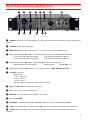
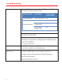
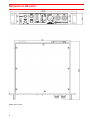
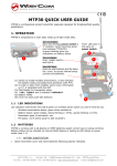
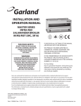
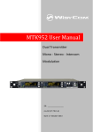
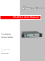
MSR916 User Manual True diversity Receiver Module SN: ________________ Rev. 01 Date: 26 July 2013 FEATURES Available in various ranges: VHF ⇒ 150 ÷ 250 MHz, UHF ⇒ 470 ÷ 880 MHz Wide pre-tuned switching-window: ⇒ 15 MHz in 140 ÷ 250 MHz range, ⇒ 15 MHz (VHF) ; 32 MHz (UHF) 16 switchable frequencies Easy PC frequency-reprogramming by the user (in the pre-tuned switching-window). Friendly factory frequency re-allocation (in the whole working-range). Broadcast superlative quality of any audio-signal transposition. Suitable for very complex multi-channel systems thanks to the extraordinarily high intermodulation immunity and RF/IF selectivity. Very easy and friendly to operate. Exceptional sturdiness and absolute reliability. SAFETY INSTRUCTION 1 Read this safety instruction and the manual first Follow all instructions and information. Do not lose this manual. Do not use this apparatus under the rain or near the water. Do not install the apparatus near heaters or in hot environments, do not use outside the operating temperature range. Do not open the apparatus, only qualified service technician are enabled to operate on it. The apparatus needs servicing when it is not properly working or is damaged by liquids, moisture or other objects are fallen in the apparatus. Use only accessories or replacement parts authorized or specified by the manufacturer. Clean the apparatus only with dry cloths, do not use liquids. Report the serial number and the purchasing date in front of the manual. It is needed to have proper replacement parts or accessories from the manufacturer. When replacement parts are needed, use only replacement parts authorized from the manufacturer. Substitution with not authorized parts could result in electric shock, hazards or fire. Keep attention on all the labels with warnings or hazards on the apparatus. FRONT PANEL CONTROL AND FUNCTIONS ❶ ❷ ❸ ❾ ❿ ⓫ ❹ ⓬ ❺ ❻ ❼ ❽ ⓭ ⓮ ❶ REMOTE indication. The red Led lights is on when the remote control interface is active (optional, on request). ❷ CHANNEL switch (with back-light). ❸ MONITOR output connector (standard ¼”, i.e. 6.3 mm, stereo jack, parallel wired). ❹ Multifunction display, RF section. The following parameters are simultaneously displayed: “A” antenna RF-signal (bar-graph) “A” antenna selected (Led A is on) “B” antenna RF-signal (bar-graph) “B” antenna selected (Led B is on). ❺ Multifunction display, AF section. The following parameters are displayed: AF line output level (bar-graph) Open squelch (Led AF ON is on). ❻ Multifunction display, Batt. section ( TX % battery lifetime: 100%, 75%, 50%, 25%, 12%). ❼ LINE OUT connector. XLR3-M type: pin 1 = ground; pin 2 = AF-a; pin 3 = AF-b The line-output is transformer-balanced and floating. ❽ RXA and RXB antenna connectors (N-F type). ❾ ON on/off switch (with Led indication). ❿ SQUELCH threshold adjustment (between 0 ÷ 50 V). ⓫ Monitor VOLUME. ⓬ CH GROUP: channel’s group switch [ #1 / #2 ] (when on, green Led indicates group #1). ⓭ T.SQL: tone-squelch function switch [ On / Off ] (when on, yellow Led indicates tone-squelch on). ⓮ P.TONE (Pilot Tone) indication. The yellow Led lights on when the matching pilot sub-carrier is received. 2 REAR PANEL ⓯ ⓰ ⓱ ⓯ Connector for remote-control interface (type D25-F connector) Optional, on request. ⓰ Product Label reports the following information: Product code Serial number Compander (ENR or NR) Band limits Option ⓱ DC-input connector (XLR4-M type) Powering: 10.5 16 Vdc, 500 mA max. pin 1 & 3 = ground; pin 4 = +Vcc input; pin 2 = +Vcc output controlled by squelch-relais. 3 PUTTING INTO OPERATION Connect the power supply to the XLR4-M connector ⓱ (see optionals PSP910-X4) Connect the antennas to the N-F antenna connectors ❽ Connect the mixer/amplifier to the Line out connector ❼ Put the selector ❾ to ON and verify the led indicator is turned on Turn off all the transmitters Chose the desired frequency rotating the Channel switch ❷ (prefer a channel with no RF level or low level on bars ❹) NOTE: a label placed on the top of the receiver shows the pre-configured frequencies list on the 2 groups (16 + 16 frequencies) . Selector ⓬ allows to change group#1-group#2. Select the appropriate squelch turning the knob from 0µV to 50µV: increase gradually the squelch level and stop when there is no RF level on bars ❹ Switch on the transmitter (on the same frequency of the MSR16) verify the AF ON indicator is ON NOTE: AF ON indicator reports the state of the audio output on connector ❼ : led ON presence of audio output led OFF absence of audio output See troubleshooting section for more details verify the bar ❺ (AF line output level) and adjust the audio gain on the transmitter in order to avoid clipping (never red levels on AF bar) NOTE: using Wisycom transmitter only : if the transmitter sends the pilot sub-carrier, the P.TONE indicator ⓮ turns on with yellow colour and the battery charger of the transmitter is shown on bar ❻ of the MSR916 if the T.SQL selector is set to ON, the audio output is enabled only if the tone squelch is detected (P.TONE indicator yellow) and the RF level is above the squelch level 4 Troubleshooting No audio output Check AF ON indicator: if it is OFF, verify T.SQL and SQUELCH setting according the following table SQUELCH setting T.SQL setting AF ONaudio output enabled RF level<SQUELCH T.SQL = OFF or ON off T.SQL = OFF on T.SQL = ON & P.TONE is OFF off T.SQL = ON & P.TONE is ON on RF level>SQUELCH Check RF level bar: if they shows no level or low level, try to decrease the squelch level If T.SQL is set to ON but the P.TONE indicator is OFF check on the transmitter’s configuration if the Wisycom pilot sub-carries is enabled change T.SQL to OFF no levels on battery bar check on the transmitter’s configuration if the Wisycom pilot sub-carries is enabled to send battery data Distortion or unwanted noise bursts Remove nearby sources of RF interference (CD players, computers, digital effects, in-ear monitor system, etc.) Change receiver and transmitter to a different frequency Reduce transmitter gain Replace transmitter batteries 5 TECHNICAL SPECIFICATIONS Switchable channels : Channel groups Switching-window Frequencies : : : Frequency error Temperature range Modulation Nominal deviation : : : : “A” / “B” antenna inputs Sensitivity (ENR) : : Amplitude response Co-channel rejection Adjacent chan. selectivity Spurious rec. rejection IF image rejection Intermodul. rejection Spurious emissions Squelch : : : : : : : : Squelch-controlled DC outputpower : “Noise reduction” system : : AF line output AF output level AF bandwidth : : : Distortion SND/N ratio (ENR) Monitor output Monitor output level : : : : Diversity technology : Remote diversity function : 16 + 16 preset in the 150 ÷ 250 MHz (VHF) or 470 ÷ 880 MHz (UHF) range (others on request). 2, externally selectable. 15 MHz (VHF); 32MHz (UHF). microprocessor controlled PLL frequency synthesizer circuit, with 25 KHz minimum step.They can be easily user-reprogrammed by PC and optional “UPK32 or UPK100 Programming kit”. < ± 5 ppm, in the rated temperature range -10 ÷ +55 °C FM, with 50 µs de-emphasis. ±20 kHz @ 1 kHz. (Max. deviation = ±75 KHz). ±40 KHz @ 1 kHz (Peak deviation = ±60 KHz). with N-F connectors. RF input impedance = 50 ohm (SWR < 1:2; typ. 1:1.4). < 2 µV ( +6 dBµV), for SND/N = 84 dB [1], < 10 µV (+20 dBµV), for SND/N = 96 dB [1], in the whole switching-range. < 0.2 dB (for RF input signal between +4 dBµV ÷ +120 dBµV). > -3.5 dB @ 2 µV RF; > -1.5 dB @ 100 µV RF. > 90 dB (for channel spacing 400 kHz). > 93 dB. > 98 dB. > 76 dB. IIP3 (Input 3°-order Intercept Point) = +9 dBm. < 10pW (typ. = 0.1 pW). field-strength: with externally adjustable threshold and adaptive-mode working (the receiver adapts itself to the different situations of medium signal-strength levels and fading-speeds). tone-squelch: with decoding of the matching sub-carrier, digitally modulated, generated by the relevant transmitter. This function can be switched-off for the compatibility with other brand TXs. is controlled by the squelch circuit. When the AF output line is active, the DC inputpower is connected to pin 2 of the XLR4-M - DC input-connector on rear-panel (max current = 2A). compander circuit, can be internally pre-set to (or eventually switched off) on following modes: ENR (Wisycom Extended-NR; NR (standard NR), to be compatible with other systems. transformer balanced, floating. Output impedance = < 50 ohm. +10 dBu (2450 mVrms), @ ±40 KHz deviation 20 Hz ÷ 20 kHz. Frequency response = ±0.5 dB (±0.2 dB typ.) in the 30 Hz ÷ 20 kHz range. < 0.3 % (0.15 % typ.) @ ±40 KHz deviation (< 0.5 % @ peak deviation). > 105 dB (115 dB typ.) [1]. ¼” (6.3 mm) stereo jack connector, mono wired, on the front panel. max 3 Vrms / 200 ohm, with volume control. Monitor output impedance = 35 ohm. true-diversity (Twin receiver circuits, with high-speed and low-noise electronic switching). the MSR916 receiver, along with audio signal on the line-output, is signalling also the RSSI level. A Centralized Automatic Selector (i.e.: RDA41, suitable for 4 remote receivers) can use this voting information to use in any time select the best audio signal. 6 Bar-graph meters : Led indications : Powering : Size Weight : : RF field strengths (both “A” and “B” antennas at the same time ) AF output level (-20 ÷ +12 dBu). TX battery lifetime, 5 steps: 100%, 75%, 50%, 25%, 12% (the last Led blinks ). diversity switching (“A” / “B” antenna) AF output-line is active (AF ON) matching sub-carrier is present (P.TONE) channel Group 1 selected (#1) tone-squelch function is on (T.SQL) receiver on. 10.5 ÷ 16 Vdc / 4 W (typ.: 350 mA @ 12 Vdc), negative ground mains 100 ÷ 240 Vac, by means of separated PSP910-X4 “mains-plug” power supply. 240,99 x 225,2 x 43,6 mm (WxDxH) 1.7 Kg approx. Note [1]: RMS value, unweighted, 22 Hz / 22 kHz, and referred to the peak deviation. 7 OPTIONALS: AGN00 - Groundplane antenna VHF/UHF AMN 05 - Magnetic-base antenna UHF, (with 5 m RG58 coax cable). AMN 05-V - Magnetic-base antenna VHF, (with 5 m RG58 coax cable). CDC 150-X4 - External 12 Vdc powering cable (1.5 m). PSP 910-X4 - 100 ÷ 240 Vac mains-plug power supply. RCD 915 - Remote control and monitoring interface (parallel type) UPK 100 - Working frequencies user programming kit (Interface + software). 8 MECHANICAL DRAWING Note: unit is mm 9 10 • WISYCOM srl • Via Spin 156 • I-36060 Romano d’Ezzelino • Italy Tel. +39 -0424 -382605 • Fax +39 - 0424 – 382733 • www.wisycom.com • e-mail: [email protected] 11