1
ConneXium Ethernet Cabling System
31007130.03
TCSESM, TCSESM-E Managed Switch
Command Line Interface Reference Manual
www.schneider-electric.com
31007130 - 03/2010
Content
Content
Safety information
15
About this Manual
17
Validity Note
Product Related Information
User Comments
Related Documents
17
17
17
18
1
Command Structure
19
1.1
Format
1.1.1 Command
1.1.2 Parameters
1.1.3 Values
1.1.4 Conventions
1.1.5 Annotations
1.1.6 Special keys
1.1.7 Special characters in scripts
1.1.8 Secrets in scripts
1.1.9 Unit-Slot-Port Naming Convention
20
21
21
22
24
25
26
27
29
30
2
Quick Start up
31
2.1
Quick Starting the Switch
32
2.2
System Info and System Setup
33
3
Mode-based CLI
39
3.1
Mode-based Topology
41
3.2
Mode-based Command Hierarchy
42
3.3
Flow of Operation
44
3.4
“No” Form of a Command
3.4.1 Support for “No” Form
3.4.2 Behavior of Command Help ("?")
46
46
46
31007130 - 03/2010
3
Content
4
CLI Commands: Base
47
4.1
System Information and Statistics Commands
4.1.1 show address-conflict
4.1.2 show arp switch
4.1.3 show bridge address-learning
4.1.4 show bridge aging-time
4.1.5 show bridge fast-link-detection
4.1.6 show bridge framesize
4.1.7 show bridge vlan-learning
4.1.8 bridge framesize
4.1.9 show config-watchdog
4.1.10show device-status
4.1.11show authentication
4.1.12show classofservice
4.1.13show eventlog
4.1.14show interface
4.1.15show interface ethernet
4.1.16show interface switchport
4.1.17show logging
4.1.18show mac-addr-table
4.1.19show signal-contact
4.1.20show slot
4.1.21show running-config
4.1.22show sysinfo
4.1.23show temperature
4.1.24snmp-server
48
48
48
49
49
49
50
50
51
51
52
53
53
54
55
57
65
65
66
67
68
68
70
72
72
4.2
Management VLAN Commands
4.2.1 network mgmt_vlan
73
73
4.3
Class of Service (CoS) Commands
4.3.1 classofservice dot1p-mapping
4.3.2 classofservice ip-dscp-mapping
4.3.3 classofservice trust
4.3.4 show classofservice dot1p-mapping
4.3.5 show classofservice ip-dscp-mapping
4.3.6 show classofservice trust
4.3.7 vlan port priority all
4.3.8 vlan priority
74
75
76
77
78
79
80
81
81
4.4
Management Commands
4.4.1 transport input telnet
82
82
4
31007130 - 03/2010
Content
4.4.2 bridge address-learning
4.4.3 bridge aging-time
4.4.4 bridge fast-link-detection
4.4.5 bridge vlan-learning
4.4.6 ethernet-ip
4.4.7 network javascriptmode
4.4.8 network parms
4.4.9 network protocol
4.4.10network priority
4.4.11serial timeout
4.4.12set prompt
4.4.13show ethernet-ip
4.4.14show network
4.4.15show serial
4.4.16show snmp-access
4.4.17show snmpcommunity
4.4.18show snmptrap
4.4.19show telnetcon
4.4.20show trapflags
4.4.21snmp-access global
4.4.22snmp-access version
4.4.23snmp-server community
4.4.24snmp-server community ipaddr
4.4.25snmp-server community ipmask
4.4.26snmp-server community mode
4.4.27snmp-server community ro
4.4.28snmp-server community rw
4.4.29snmp-server location
4.4.30snmp-server sysname
4.4.31snmp-server enable traps
4.4.32snmp-server enable traps chassis
4.4.33snmp-server enable traps l2redundancy
4.4.34snmp-server enable traps linkmode
4.4.35snmp-server enable traps multiusers
4.4.36snmp-server enable traps port-sec
4.4.37snmp-server enable traps stpmode
4.4.38snmptrap
4.4.39snmptrap ipaddr
4.4.40snmptrap mode
4.4.41snmptrap snmpversion
4.4.42telnetcon maxsessions
31007130 - 03/2010
83
84
85
85
85
86
87
87
88
89
90
90
91
92
93
93
95
96
97
98
99
100
101
102
103
104
104
104
105
106
107
108
109
110
111
112
113
114
115
116
117
5
Content
4.4.43telnetcon timeout
118
4.5
Syslog Commands
4.5.1 logging buffered
4.5.2 logging buffered wrap
4.5.3 logging cli-command
4.5.4 logging console
4.5.5 logging host
4.5.6 logging host reconfigure
4.5.7 logging host remove
4.5.8 Global Configlogging syslog
4.5.9 logging syslog port
119
119
120
121
122
123
124
124
125
125
4.6
Scripting Commands
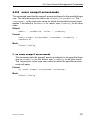
4.6.1 script apply
4.6.2 script delete
4.6.3 script list
4.6.4 script show
4.6.5 script validate
126
126
127
127
128
128
4.7
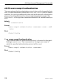
Device Configuration Commands
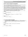
4.7.1 auto-negotiate
4.7.2 cable-crossing
4.7.3 auto-negotiate all
4.7.4 media-module remove
4.7.5 macfilter
4.7.6 macfilter adddest
4.7.7 macfilter adddest all
4.7.8 monitor session <session-id>
4.7.9 monitor session <session-id> mode
4.7.10monitor session <session-id> source/destination
4.7.11rmon-alarm add
4.7.12rmon-alarm delete
4.7.13rmon-alarm enable
4.7.14rmon-alarm disable
4.7.15rmon-alarm modify mib-variable
4.7.16rmon-alarm modify thresholds
4.7.17rmon-alarm modify interval
4.7.18rmon-alarm modify sample-type
4.7.19rmon-alarm modify startup-alarm
4.7.20rmon-alarm modify rising-event
4.7.21rmon-alarm modify falling-event
129
129
130
131
131
132
133
134
135
136
137
138
138
139
139
140
140
141
141
142
143
143
6
31007130 - 03/2010
Content
4.7.22set garp timer join
4.7.23set garp timer leave
4.7.24set garp timer leaveall
4.7.25set gmrp adminmode
4.7.26set gmrp interfacemode
4.7.27set gmrp interfacemode
4.7.28set gmrp forward-all-groups
4.7.29set igmp
4.7.30set igmp
4.7.31set igmp aging-time-unknown
4.7.32set igmp automatic-mode
4.7.33set igmp forward-all
4.7.34set igmp forward-unknown
4.7.35set igmp static-query-port
4.7.36set igmp groupmembershipinterval
4.7.37set igmp interfacemode
4.7.38set igmp lookup-interval-unknown
4.7.39set igmp lookup-resp-time-unknown
4.7.40set igmp maxresponse
4.7.41set igmp querier max-response-time
4.7.42set igmp querier protocol-version
4.7.43set igmp querier status
4.7.44set igmp querier tx-interval
4.7.45set igmp query-ports-to-filter
4.7.46selftest ramtest
4.7.47selftest reboot-on-error
4.7.48show garp
4.7.49show gmrp configuration
4.7.50show igmpsnooping
4.7.51show mac-filter-table gmrp
4.7.52show mac-filter-table igmpsnooping
4.7.53show mac-filter-table multicast
4.7.54show mac-filter-table static
4.7.55show mac-filter-table staticfiltering
4.7.56show mac-filter-table stats
4.7.57show monitor
4.7.58show monitor session
4.7.59show port
4.7.60show rmon-alarm
4.7.61show selftest
4.7.62show storm-control
31007130 - 03/2010
144
145
146
147
148
149
150
151
152
153
153
154
155
156
157
158
159
159
160
161
161
162
162
163
164
164
165
166
168
170
171
172
173
174
175
176
176
177
179
179
180
7
Content
4.8
8
4.7.63show storm-control limiters port
4.7.64show vlan
4.7.65show vlan brief
4.7.66show vlan port
4.7.67shutdown
4.7.68shutdown all
4.7.69snmp trap link-status
4.7.70snmp trap link-status all
4.7.71spanning-tree bpdumigrationcheck
4.7.72speed
4.7.73storm-control broadcast
4.7.74storm-control egress-limiting
4.7.75storm-control ingress-limiting
4.7.76storm-control broadcast (port-related)
4.7.77storm-control egress-limit
4.7.78storm-control ingress-limit
4.7.79storm-control ingress-mode
4.7.80storm-control flowcontrol
4.7.81vlan
4.7.82vlan0-transparent-mode
4.7.83vlan acceptframe
4.7.84vlan database
4.7.85vlan ingressfilter
4.7.86vlan name
4.7.87vlan participation
4.7.88vlan participation all
4.7.89vlan port acceptframe all
4.7.90vlan port ingressfilter all
4.7.91vlan port pvid all
4.7.92vlan port tagging all
4.7.93vlan pvid
4.7.94vlan tagging
181
181
183
184
185
186
187
188
189
190
191
192
192
192
193
193
193
194
195
196
197
198
199
200
201
202
203
204
205
206
207
208
User Account Management Commands
4.8.1 disconnect
4.8.2 show loginsession
4.8.3 show users
4.8.4 users defaultlogin
4.8.5 users login <user>
4.8.6 users access
4.8.7 users name
209
209
210
211
212
213
214
215
31007130 - 03/2010
Content
4.9
4.8.8 users passwd
4.8.9 users snmpv3 accessmode
4.8.10users snmpv3 authentication
4.8.11 users snmpv3 encryption
216
217
218
219
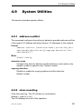
System Utilities
4.9.1 address-conflict
4.9.2 clear eventlog
4.9.3 traceroute
4.9.4 clear arp-table-switch
4.9.5 clear config
4.9.6 clear config factory
4.9.7 clear counters
4.9.8 clear hiper-ring
4.9.9 clear igmpsnooping
4.9.10clear mac-addr-table
4.9.11clear pass
4.9.12clear signal-contact
4.9.13clear traplog
4.9.14clear ring-coupling
4.9.15clear vlan
4.9.16config-watchdog
4.9.17copy
4.9.18device-status
4.9.19device-status
4.9.20logout
4.9.21ping
4.9.22signal-contact connection-error
4.9.23signal-contact
4.9.24temperature
4.9.25reboot
4.9.26reload
221
221
221
222
222
223
223
223
224
225
225
226
226
226
227
228
229
230
231
231
232
233
233
234
235
236
236
4.10 LLDP - Link Layer Discovery Protocol
4.10.1show lldp
4.10.2show lldp config
4.10.3show lldp config chassis
4.10.4show lldp config chassis admin-state
4.10.5show lldp config chassis notification-interval
4.10.6show lldp config chassis re-init-delay
4.10.7show lldp config chassis tx-delay
4.10.8show lldp config chassis tx-hold-mult
31007130 - 03/2010
237
237
237
238
238
239
239
240
240
9
Content
4.10.9show lldp config chassis tx-interval
4.10.10show lldp config port
4.10.11show lldp config port tlv
4.10.12show lldp remote-data
4.10.13lldp
4.10.14lldp config chassis admin-state
4.10.15lldp config chassis notification-interval
4.10.16lldp config chassis re-init-delay
4.10.17lldp config chassis tx-delay
4.10.18lldp config chassis tx-hold-mult
4.10.19lldp chassis tx-interval
4.10.20clear lldp config all
4.10.21lldp admin-state
4.10.22lldp fdb-mode
4.10.23lldp sa-mode
4.10.24lldp hm-mode
4.10.25lldp max-neighbors
4.10.26lldp notification
4.10.27lldp tlv link-aggregation
4.10.28lldp tlv mac-phy-config-state
4.10.29lldp tlv max-frame-size
4.10.30lldp tlv mgmt-addr
4.10.31lldp tlv port-desc
4.10.32lldp tlv port-vlan
4.10.33lldp tlv gmrp
4.10.34lldp tlv igmp
4.10.35lldp tlv portsec
4.10.36lldp tlv ptp
4.10.37lldp tlv protocol
4.10.38lldp tlv sys-cap
4.10.39lldp tlv sys-desc
4.10.40lldp tlv sys-name
4.10.41lldp tlv vlan-name
4.10.42name
4.11 SNTP - Simple Network Time Protocol
4.11.1show sntp
4.11.2show sntp anycast
4.11.3show sntp client
4.11.4show sntp operation
4.11.5show sntp server
10
240
241
242
243
244
245
245
246
246
247
247
248
248
249
250
251
251
252
252
252
253
253
253
254
254
254
255
255
255
256
256
256
257
257
259
259
259
260
261
261
31007130 - 03/2010
Content
4.11.6show sntp status
4.11.7show sntp time
4.11.8no sntp
4.11.9sntp anycast address
4.11.10sntp anycast transmit-interval
4.11.11sntp anycast vlan
4.11.12sntp client accept-broadcast
4.11.13sntp client disable-after-sync
4.11.14sntp client offset
4.11.15sntp client request-interval
4.11.16no sntp client server
4.11.17sntp client server primary
4.11.18sntp client server secondary
4.11.19sntp client threshold
4.11.20sntp operation
4.11.21sntp server disable-if-local
4.11.22sntp time system
262
263
263
264
264
265
265
266
266
267
267
267
269
270
271
271
272
4.12 PTP - Precision Time Protocol
4.12.1show ptp
4.12.2ptp clock-mode
4.12.3ptp operation
273
273
273
274
5
CLI Commands: Switching
275
5.1
Spanning Tree Commands
5.1.1 show spanning-tree
5.1.2 show spanning-tree interface
5.1.3 show spanning-tree mst detailed
5.1.4 show spanning-tree mst port detailed
5.1.5 show spanning-tree mst port summary
5.1.6 show spanning-tree summary
5.1.7 show spanning-tree vlan
5.1.8 spanning-tree
5.1.9 spanning-tree auto-edgeport
5.1.10spanning-tree configuration name
5.1.11spanning-tree configuration revision
5.1.12spanning-tree edgeport
5.1.13spanning-tree forceversion
5.1.14spanning-tree forward-time
5.1.15spanning-tree hello-time
5.1.16spanning-tree max-age
277
277
279
280
281
284
285
286
287
288
289
290
291
292
293
294
295
31007130 - 03/2010
11
Content
5.1.17spanning-tree max-hops
5.1.18spanning-tree mst
5.1.19spanning-tree mst priority
5.1.20spanning-tree mst vlan
5.1.21spanning-tree port mode
5.1.22spanning-tree port mode all
5.1.23spanning-tree stp-mrp-mode
296
297
299
300
301
302
303
MRP
5.2.1
5.2.2
5.2.3
5.2.4
5.2.5
5.2.6
show mrp
show mrp current-domain
mrp
mrp current-domain
mrp delete-domain
mrp new-domain
305
305
306
307
308
309
309
5.3
HIPER-Ring
5.3.1 show hiper-ring
5.3.2 show hiper-ring info
5.3.3 hiper-ring
5.3.4 hiper-ring mode
5.3.5 hiper-ring port primary
5.3.6 hiper-ring port secondary
5.3.7 hiper-ring recovery-delay
311
312
313
313
314
314
315
315
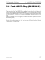
5.4
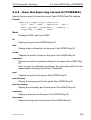
Fast-HIPER-Ring (TCSESM-E)
5.4.1 show fast-hiper-ring (TCSESM-E)
5.4.2 show fast-hiper-ring current-id (TCSESM-E)
5.4.3 fast-hiper-ring
317
318
319
320
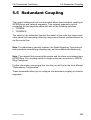
5.5
Redundant Coupling
5.5.1 show ring-coupling
5.5.2 ring-coupling
5.5.3 ring-coupling config
5.5.4 ring-coupling net-coupling
5.5.5 ring-coupling operation
5.5.6 ring-coupling port
5.5.7 ring-coupling redundancy-mode
323
324
326
327
328
328
329
329
5.6
Port Security
5.6.1 show port-sec mode
5.6.2 show port-sec port
5.6.3 port-sec mode
5.6.4 port-sec action
331
331
331
332
332
5.2
12
31007130 - 03/2010
Content
5.6.5 port-sec allowed-ip
5.6.6 port-sec allowed-mac
5.6.7 clear port-sec
333
333
334
5.7
DHCP Relay Commands
5.7.1 show dhcp-relay
5.7.2 dhcp-relay
5.7.3 dhcp-relay
335
335
336
337
5.8
Sub-Ring Commands
(TCSESM-E) 339
5.8.1 show sub-ring
5.8.2 sub-ring <id> mode
5.8.3 sub-ring <id> operation
5.8.4 sub-ring <id> protocol
5.8.5 sub-ring <id> port
5.8.6 sub-ring <id> ring-name
5.8.7 sub-ring <id> vlan
5.8.8 sub-ring <id> mrp-domainID
5.8.9 sub-ring delete-ring
5.8.10sub-ring new-ring
339
341
342
342
343
343
344
345
346
346
6
CLI Commands: Security
347
6.1
Security Commands
6.1.1 authentication login
6.1.2 show authentication
6.1.3 show authentication users
6.1.4 show users authentication
6.1.5 users defaultlogin
6.1.6 users login
349
349
351
352
353
354
355
6.2
HTTP Commands
6.2.1 ip http secure-port
6.2.2 ip http secure-protocol
6.2.3 ip http server
6.2.4 show ip http
357
357
358
359
360
7
Appendix- VLAN Example
361
7.1
SOLUTION 1
363
7.2
SOLUTION 2
365
31007130 - 03/2010
13
Content
8
Glossary
367
9
Index
383
14
31007130 - 03/2010
Safety information
Safety information
U Important Information
Notice:
Read these instructions carefully, and look at the equipment to
become familiar with the device before trying to install, operate, or
maintain it. The following special messages may appear throughout
this documentation or on the equipment to warn of potential hazards
or to call attention to information that clarifies or simplifies a
procedure.
31007130 - 03/2010
15
Safety information
PLEASE NOTE:
Electrical equipment should be installed, operated, serviced, and
maintained only by qualified personnel.
No responsibility is assumed by Schneider Electric for any
consequences arising out of the use of this material.
© 2009 Schneider Electric. All Rights Reserved.
16
31007130 - 03/2010
About this Manual
About this Manual
Validity Note
The data and illustrations found in this book are not binding. We reserve the
right to modify our products in line with our policy of continuous product
development. The information in this document is subject to change without
notice and should not be construed as a commitment by Schneider Electric.
Product Related Information
Schneider Electric assumes no responsibility for any errors that may appear
in this document. If you have any suggestions for improvements or amendments or have found errors in this publication, please notify us.
No part of this document may be reproduced in any form or by any means,
electronic or mechanical, including photocopying, without express written
permission of Schneider Electric.
All pertinent state, regional, and local safety regulations must be observed
when installing and using this product. For reasons of safety and to ensure
compliance with documented system data, only the manufacturer should
perform repairs to components.
When devices are used for applications with technical safety requirements,
please follow the relevant instructions.
Failure to use Schneider Electric software or approved software with our
hardware products may result in improper operating results.
Failure to observe this product related warning can result in injury or
equipment damage.
User Comments
We welcome your comments about this document. You can reach us by
email at [email protected]
31007130 - 03/2010
17
About this Manual
Related Documents
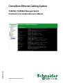
Title of Documentation
ConneXium Ethernet Cabling System Managed Switch
User Manual Redundancy Configuration
ConneXium Ethernet Cabling System Managed Switch
User Manual Basic Configuration
ConneXium Ethernet Cabling System Managed Switch
Reference Manual Command Line Interface
ConneXium Ethernet Cabling System Managed Switch
Reference Manual Web-based Interface
ConneXium Ethernet Cabling System Managed Switch
Installation Manual TCSESM
ConneXium Ethernet Cabling System Managed Switch
Installation Manual TCSESM-E
Reference-Number
31007126.03
31007122.04
31007130.03
EIO0000000482.01
31007118.05
EIO0000000529.01
Note: The Glossary you will find in the Reference Manual Command Line
Interface.
The "Web-based Interface" reference manual contains detailed information
on using the Web interface to operate the individual functions of the device.
The "Command Line Interface" reference manual contains detailed information on using the Command Line Interface to operate the individual functions
of the device.
The “Installation” user manual contains a device description, safety instructions, a description of the display, and the other information that you need to
install the device before you begin with the configuration of the device.
The “Basic Configuration” user manual contains the information you need to
start operating the device. It takes you step by step from the first startup
operation through to the basic settings for operation in your environment.
The “Redundancy Configuration” user manual contains the information you
need to select a suitable redundancy procedure and configure it.
18
31007130 - 03/2010
Command Structure
1 Command Structure
The Command Line Interface (CLI) syntax, conventions and terminology are
described in this section. Each CLI command is illustrated using the structure
outlined below.
31007130 - 03/2010
19
Command Structure
1.1 Format
1.1 Format
Some commands, such as clear vlan, do not require parameters. Other
commands, such as network parms, have parameters for which you must
supply a value. Parameters are positional — you must type the values in the
correct order. Optional parameters will follow required parameters. For example:
U Example 1
network parms <ipaddr> <netmask> [gateway]
D network parms
is the command name.
D <ipaddr> <netmask>
are the required values for the command.
D [gateway]
is the optional value for the command.
U Example 2
snmp-server location <loc>
D snmp-server location
is the command name.
D <loc>
is the required parameter for the command.
U Example 3
clear config
D clear config
is the command name.
U Example 3
clear vlan
D clear vlan
is the command name.
20
31007130 - 03/2010
Command Structure
1.1 Format
1.1.1 Command
The following conventions apply to the command name:
D The command name is displayed in this document in courier font and is
to be typed exactly as shown.
D Once you have entered enough letters of a command name to uniquely
identify the command, pressing the <Space bar> or <Tab key> will
cause the system to complete the word.
D Entering Ctrl-Z will return you to the root level command prompt.
1.1.2 Parameters
Parameters are order dependent.
Parameters are displayed in this document in italic font, which are to
be replaced with a name or number.
To use spaces as part of a name parameter, enclose it in double quotes. For
example, the expression "System Name with Spaces" forces the system to
accept the spaces.
Parameters may be mandatory values, optional values, choices, or a combination.
D <parameter>. The <> angle brackets indicate that a mandatory parameter is to be entered in place of the brackets and text inside them.
D [parameter]. The [] square brackets indicate that an optional parameter may be entered in place of the brackets and text inside them.
D choice1 | choice2. Vertical bars ‘|’ separate alternative, mutually exclusive, elements.
D The {} curly braces indicate that a parameter must be chosen from the list
of choices.
D Braces within square brackets [{}] indicate a required choice within an optional element.
31007130 - 03/2010
21
Command Structure
1.1 Format
1.1.3 Values
ipaddr
This parameter is a valid IP address. Presently the IP address can be entered in following formats:
a (32 bits)
a.b (8.24 bits)
a.b.c (8.8.16 bits)
a.b.c.d (8.8.8.8)
In addition to these formats, decimal, hexidecimal and octal formats are supported
through the following input formats (where
n is any valid hexidecimal, octal or decimal
number):
0xn (CLI assumes hexidecimal format)
0n (CLI assumes octal format with leading
zeros)
n (CLI assumes decimal format)
macaddr
The MAC address format is six hexadecimal numbers separated by colons, for
example 00:06:29:32:81:40.
areaid
Area IDs may be entered in dotted-decimal
notation (for example, 0.0.0.1). An area ID
of 0.0.0.0 is reserved for the backbone.
Area IDs have the same form as IP
addresses, but are distinct from IP
addresses. The IP network number of the
sub-netted network may be used for the
area ID.
outerid
The value of <router id> must be entered in
4-digit dotted-decimal notation (for example, 0.0.0.1). A router ID of 0.0.0.0 is
invalid.
Valid slot and port number separated by
forward slashes. For example, 0/1 represents slot number 0 and port number 1.
Interface
22
31007130 - 03/2010
Command Structure
1.1 Format
See “Unit-Slot-Port Naming Convention”
on page 30.
Logical Interface
Logical slot and port number. This is applicable in the case of a port-channel (LAG).
The operator can use the logical slot/port to
configure the port-channel. See “Unit-SlotPort Naming Convention” on page 30.
Character strings Use double quotation marks to identify character
strings, for example, “System Name with Spaces”. An empty string (“”) is not
valid.
31007130 - 03/2010
23
Command Structure
1.1 Format
1.1.4 Conventions
Network addresses are used to define a link to a remote host, workstation or
network. Network addresses are shown using the following syntax:
Address Type
ipaddr
macaddr
Format
192.168.11.110
A7:C9:89:DD:A9:B3
Range
0.0.0.0 to 255.255.255.255 (decimal)
hexidecimal digit pairs
Table 1: Network Address Syntax
Double quotation marks such as "System Name with Spaces" set off user defined strings. If the operator wishes to use spaces as part of a name parameter then it must be enclosed in double quotation marks.
Empty strings (““) are not valid user defined strings.
Command completion finishes spelling the command when enough letters of
a command are typed to uniquely identify the command word. The command
may be executed by typing <enter> (command abbreviation) or the command word may be completed by typing the <tab> or <space bar> (command
completion).
The value 'Err' designates that the requested value was not internally accessible.
The value of '-----' designates that the value is unknown.
24
31007130 - 03/2010
Command Structure
1.1 Format
1.1.5 Annotations
The CLI allows the user to type single-line annotations at the command
prompt for use when writing test or configuration scripts and for better readability. The exclamation point (‘!’) character flags the beginning of a comment. The comment flag character can begin a word anywhere on the
command line and all input following this character is ignored. Any command
line that begins with the character ‘!’ is recognized as a comment line and ignored by the parser.
Some examples are provided below:
! Script file for setting the CLI prompt
set prompt example-switch
! End of the script file
31007130 - 03/2010
25
Command Structure
1.1 Format
1.1.6 Special keys
Certain special key combinations speed up use of the CLI. They are listed in
this section. Also, help is available for the CLI by typing HELP:
BS
delete previous character
Ctrl-A
Ctrl-E
go to beginning of line
go to end of line
Ctrl-F
Ctrl-B
go forward one character
go backward one character
Ctrl-D
delete current character
Ctrl-H
display command history or retrieve a command
Ctrl-U, X
Ctrl-K
delete to beginning of line
delete to end of line
Ctrl-W
delete previous word
Ctrl-T
transpose previous character
Ctrl-P
go to previous line in history buffer
Ctrl-N
go to next line in history buffer
Ctrl-Z
return to root command prompt
Tab, <SPACE> command-line completion
Exit
go to next lower command prompt
?
list choices
26
31007130 - 03/2010
Command Structure
1.1 Format
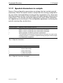
1.1.7 Special characters in scripts
Some of the configuration parameters are strings that can contain special
characters. When the switch creates a script from the running configuration
(by use of the command #show running-config <scriptname.cli>), these special characters are written to the script with a so-called escape character preceding them. This ensures that when applying the script, these characters
are regarded as a normal part of the configuration parameter, not having the
special meaning they usually have.
Character (plain)
!
"
'
?
\
Meaning, when entered in the CLI
Begin of a comment, ! and the rest of the line will be ignored
Begin or end of a string that may contain space characters
Begin or end of a string that may contain space characters
Shows possible command keywords or parameters
The backslash has no special meaning here but because it is used as the
escape character, it now bears a special meaning (this part of the concept
is not backward compatible).
Tab. 2: Special characters
Character (escaped)
\!
\"
\'
?
\
Meaning, when entered in the CLI
! is part of the string
" is part of the string
' is part of the string
? is part of the string
\ is part of the string
Tab. 3: Special characters escaped
31007130 - 03/2010
27
Command Structure
1.1 Format
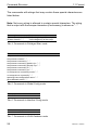
The commands with strings that may contain these special characters are
listed below.
Note: Not every string is allowed to contain special characters. The string
that is output with the escape characters (if necessary) is shown as "...".
Command
!System Description "..."
!System Version "..."
Note
"At the beginning of the script
"At the beginning of the script
Tab. 4: Commands in Privileged Exec mode
Command
snmp-server location "..."
snmp-server contact "..."
snmp-server community "..."
snmp-server community ipaddr <ip> "..."
snmp-server community ipmask <ip> "..."
snmp-server community ro "..."
snmp-server community rw "..."
no snmp-server community mode "..."
no snmp-server community "..."
spanning-tree configuration name "..."
ptp subdomain-name "..."
Note
Tab. 5: Commands in Global Config mode
Command
name "..."
Note
Tab. 6: Commands in Interface Config mode
Command
Note
vlan name <n> "..."
Tab. 7: Commands in VLAN Database mode
28
31007130 - 03/2010
Command Structure
1.1 Format
When a device creates a script, a human-readable header is included that
lists the special characters and the escape characters:
!Parameter string escape handling \, 1
!Characters to be preceded with escape char (\): \, !, ", ', ?
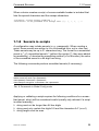
1.1.8 Secrets in scripts
A configuration may include secrets (e. g., passwords). When creating a
script, these secrets are written to it in a scrambled form, not in clear text.
These secrets may be up to 31 characters long. The format for a scrambled
secret is: ":v1:<scrambled secret>:" (without the quotes ("), they were added
for readability). v1 denotes the scrambling method (v1 in this case), the value
of the scrambled secret is a 64-digit hex string.
The following commands produce scrambled secrets (if necessary):
Command
radius server key acct <ip> <password>
radius server key auth <ip> <password>
users passwd <username> <password>
users snmpv3 encryption <username> des <password>
Note
Tab. 8: Commands in Global Config mode
Applying or validating a script requires the following conditions for a scrambled secret, else it will be considered invalid (usually only relevant if a script
is edited manually):
D string must not be longer than 64 hex digits
D string must only contain the digits 0-9 and the characters A-F (or a-f)
D string length must be even
31007130 - 03/2010
29
Command Structure
1.1 Format
1.1.9 Unit-Slot-Port Naming Convention
Switch software references physical entities such as cards and ports using a
Slot/Port naming convention. This convention is also used to identify certain
logical entities such as Link Aggregation (LAG) interfaces.
The slot number has two uses. In the case of physical ports it identifies the
card containing the ports. In the case of logical ports it also identifies the type
of interface or port.
Physical slot numbers
Physical slot numbers begin with one, and are allocated up to the
maximum number of physical slots
Logical slot numbers
Logical slots immediately follow physical slots and identify LAG or
router interfaces. For LAG the slot number 8 is used. For VLAN interfaces the slot number 9 is used.
The port identifies the specific physical port or logical interface being managed on a given slot.
Physical Ports
The physical ports for each slot are numbered sequentially starting
from one.
Logical Interfaces
There are two types of logical interfaces: LAG and VLAN routing
interfaces.
D LAG interfaces are only used for bridging functions. Each LAG interface consists of a set of up to eight physical ports identified by their
own Slot/Port.
D VLAN routing interfaces are only used for routing functions.
30
31007130 - 03/2010
Quick Start up
2 Quick Start up
The CLI Quick Start up details procedures to quickly become acquainted with
the software.
31007130 - 03/2010
31
Quick Start up
2.1 Quick Starting the Switch
2.1 Quick Starting the Switch
D Read the device Installation Guide for the connectivity procedure. In-band
connectivity allows access to the software locally or from a remote workstation. The device must be configured with IP information (IP address,
subnet mask, and default gateway).
D Turn the Power ON.
D Allow the device to load the software until the login prompt appears. The
device initial state is called the default mode.
D When the prompt asks for operator login, execute the following steps:
D Type the word admin in the login area. Since a number of the Quick
Setup commands require administrator account rights, CLI suggests
logging into an administrator account.
D Enter the state on delivery password private.
D Press the enter key twice.
D The CLI User EXEC prompt will be displayed.
User EXEC prompt:
(Schneider Product) >
D Use “enable” to switch to the Privileged EXEC mode from User EXEC.
Privileged EXEC prompt:
(Schneider Product) #
D Use “configure” to switch to the Global Config mode from Privileged
EXEC.
Global Config prompt:
(Schneider Product) (Config)#
D Use “exit” to return to the previous mode.
32
31007130 - 03/2010
Quick Start up
2.2 System Info and System Setup
2.2 System Info and System
Setup
This chapter informs you about:
D
D
D
D
D
Quick Start up Software Version Information
Quick Start up Physical Port Data
Quick Start up User Account Management
Quick Start up IP Address
Quick Start up Uploading from Switch to Out-of-Band PC
Only XMODEM)
D Quick Start up Downloading from Out-of-Band PC to Switch
(Only XMODEM)
D Quick Start up Downloading from TFTP Server
D Quick Start up Factory Defaults
31007130 - 03/2010
33
Quick Start up
2.2 System Info and System Setup
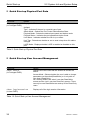
U Quick Start up Physical Port Data
Command
show port all
Details
Displays the Ports
(in Privileged EXEC)
slot/port
Type - Indicates if the port is a special type of port
Admin Mode - Selects the Port Control Administration State
Physical Mode - Selects the desired port speed and duplex mode
Physical Status - Indicates the port speed and duplex mode
Link Status - Indicates whether the link is up or down
Link Trap - Determines whether or not to send a trap when link status
changes
LACP Mode - Displays whether LACP is enabled or disabled on this
port.
Table 9: Quick Start up Physical Port Data
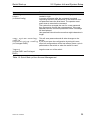
U Quick Start up User Account Management
Command
show users
(in Privileged EXEC)
Details
Displays all of the users that are allowed to access the
switch
Access Mode - Shows whether the user is able to change
parameters on the switch(Read/Write) or is only able to
view them (Read Only).
As a factory default, the ‘admin’ user has Read/Write
access and the ‘user’ user has Read Only access. There
can only be one Read/Write user and up to five Read Only
users.
show loginsession
Displays all of the login session information
(in User EXEC)
Table 10: Quick Start up User Account Management
34
31007130 - 03/2010
Quick Start up
Command
users passwd <username>
(in Global Config)
2.2 System Info and System Setup
Details
Allows the user to set passwords or change passwords
needed to login
A prompt will appear after the command is entered
requesting the users old password. In the absence of an
old password leave the area blank. The operator must
press enter to execute the command.
The system then prompts the user for a new password
then a prompt to confirm the new password. If the new
password and the confirmed password match a message
will be displayed.
User password should not be more than eight characters in
length.
copy system:running- This will save passwords and all other changes to the
config
device.
nvram:startup-config If you do not save the configuration by doing this com(in Privileged EXEC)
mand, all configurations will be lost when a power cycle is
performed on the switch or when the switch is reset.
logout
Logs the user out of the switch
(in User EXEC and Privileged
EXEC)
Table 10: Quick Start up User Account Management
31007130 - 03/2010
35
Quick Start up
2.2 System Info and System Setup
U Quick Start up IP Address
To view the network parametes the operator can access the device by the
following methods.
D Simple Network Management Protocol - SNMP
D Web Browser
Note: Helpful Hint: The user should do a ‘copy system:running-config
nvram:startup-config’ after configuring the network parameters so that the
configurations are not lost.
Command
show network
Details
Displays the Network Configurations
(in User EXEC)
IP Address - IP Address of the switch
Default IP is 0.0.0.0
Subnet Mask - IP Subnet Mask for the switch
Default is 0.0.0.0
Default Gateway - The default Gateway for this switch
Default value is 0.0.0.0
Burned in MAC Address - The Burned in MAC Address used for inband connectivity
Network Configurations Protocol (BOOTP/DHCP) - Indicates which
network protocol is being used
Default is DHCP
Network Configurations Protocol Ethernet Switch Configurator Software - Indicates the status of the Ethernet Switch Configurator Software protocol.
Default is read-write
Management VLAN Id - Specifies VLAN id
Web Mode - Indicates whether HTTP/Web is enabled.
JavaScript Mode - Indicates whether java mode is enabled.
When the user accesses the switch’s web interface and JavaScript
Mode is enabled, the switch’s web server will deliver a HTML page
that contains JavaScript. Some browsers do not support JavaScript. In
this case, a HTML page without JavaScript is necessary. In this case,
set JavaScript Mode to disabled.
Default: enabled.
network parms Sets the IP Address, subnet mask and gateway of the router. The IP
<ipaddr> <net- Address and the gateway must be on the same subnet.
mask> [gateway]
(in Privileged EXEC)
IP Address range from 0.0.0.0 to 255.255.255.255
Table 11: Quick Start up IP Address
36
31007130 - 03/2010
Quick Start up
Command
2.2 System Info and System Setup
Details
Subnet Mask range from 0.0.0.0 to 255.255.255.255
Gateway Address range from 0.0.0.0 to 255.255.255.255
Table 11: Quick Start up IP Address
U Quick Start up Downloading from TFTP Server
Before starting a TFTP server download, the operator must complete the
Quick Start up for the IP Address.
Command
copy <url> {nvram:startupconfig | system:image}
Details
Sets the destination (download) datatype to be an
image (system:image) or a configuration file
(nvram:startup-config).
The URL must be specified as:
tftp://ipAddr/filepath/fileName.
The nvram:startup-config option downloads the
configuration file using tftp and system:image
option downloads the code file.
Table 12: Quick Start up Downloading from TFTP Server
U Quick Start up Factory Defaults
Command
clear config
(in Privileged EXEC Mode)
Details
Enter yes when the prompt pops up to clear all the configurations made to the switch.
copy system:running- Enter yes when the prompt pops up that asks if you want
config nvram:startup- to save the configurations made to the switch.
config
reboot (or cold boot the switch) Enter yes when the prompt pops up that asks if you want
(in Privileged EXEC Mode)
to reset the system.
This is the users choice either reset the switch or cold
boot the switch, both work effectively.
Table 13: Quick Start up Factory Defaults
31007130 - 03/2010
37
Quick Start up
38
2.2 System Info and System Setup
31007130 - 03/2010
Mode-based CLI
3 Mode-based CLI
The CLI groups all the commands in appropriate modes according to the nature of the command. A sample of the CLI command modes are described
below. Each of the command modes support specific software commands.
D
D
D
D
D
D
D
User Exec Mode
Privileged Exec Mode
Global Config Mode
Interface Config Mode
Line Config Mode
Router RIP Config Mode
MAC Access-list Config Mode
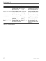
The Command Mode table captures the command modes, the prompts visible in that mode and the exit method from that mode.
Command Mode
User Exec Mode
Access Method
This is the first level of
access. Perform basic
tasks and list system
information
Privileged Exec From the User Exec
Mode
Mode, enter the
enable command
VLAN Mode
From the Privileged
User Exec mode, enter
the vlan database
command
Global Config
From the Privileged
Mode
Exec mode, enter the
configure command
Interface Config From the Global ConMode
figuration mode, enter
the interface
<slot/port> command
Prompt
(Schneider
Product)>
Exit or Access Next Mode
Enter Logout command
(Schneider
Product)#
To exit to the User Exec
mode, enter exit or press
Ctrl-Z.
To exit to the Privileged
Exec mode, enter the exit
command, or press Ctrl-Z to
switch to User Exec mode.
To exit to the Privileged
Exec mode, enter the exit
command, or press Ctrl-Z to
switch to user exec mode.
To exit to the Global Config
mode enter exit. To return to
user EXEC mode enter ctrlZ.
(Schneider
Product)
(Vlan) #
(Schneider
Product)
(Config)#
(Schneider
Product)
(Interface"if number")#
Table 14: Command Mode
31007130 - 03/2010
39
Mode-based CLI
Command Mode
Access Method
Line Config Mode From the Global Configuration mode, enter
the lineconfig
command
Router RIP Config From the Global Config
Mode
mode, enter the
router rip command
MAC Access-list From the Global Config
Config Mode
mode enter the mac
access-list
extended <name>
command.
Stack Global Config
From the Global ConMode
figuration mode, enter
the stack command
Prompt
(Schneider
Product)
(line) #
Exit or Access Next Mode
To exit to the Global Config
mode enter exit. To return to
User Exec mode enter ctrlZ.
(Schneider
To exit to the Global Config
Product)
mode enter exit. To return to
(ConfigUser Exec mode enter ctrlrouter)#
Z.
(Schneider
To exit to the Global Config
Product)
mode, enter the exit com(Config mac- mand. To return to the User
accessEXEC mode, enter Ctrl-Z.
list)#
Switch (Config- To exit to Global Configurastack )#
tion mode enter exit. To
return to user EXEC mode,
enter ctrl-Z
Table 14: Command Mode
40
31007130 - 03/2010
Mode-based CLI
3.1 Mode-based Topology
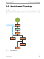
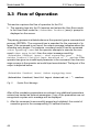
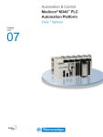
3.1 Mode-based Topology
The CLI tree is built on a mode concept where the commands are available
according to the interface. Some of the modes are depicted in the following
figure.
ROOT
The User Exec commands
are also accessible in the
Priviledged Exec mode.
User Exec
Eanable
Privileged Exec
VLAN
Global Config
Interface Config
Line Config
Fig. 1:
Mode-based CLI
31007130 - 03/2010
41
Mode-based CLI
3.2 Mode-based Command Hierarchy
3.2 Mode-based Command
Hierarchy
The CLI is divided into various modes. The Commands in one mode are not
available until the operator switches to that particular mode, with the exception of the User Exec mode commands. The User Exec mode commands
may also be executed in the Privileged Exec mode.
The commands available to the operator at any point in time depend upon
the mode. Entering a question mark (?) at the CLI prompt, displays a list of
the available commands and descriptions of the commands.
The CLI provides the following modes:
User Exec Mode
When the operator logs into the CLI, the User Exec mode is the initial
mode. The User Exec mode contains a limited set of commands. The
command prompt shown at this level is:
Command Prompt: (Schneider Product)>
Privileged Exec Mode
To have access to the full suite of commands, the operator must enter
the Privileged Exec mode. Privileged users authenticated by login are
able to enter the Privileged EXEC mode. From Privileged Exec mode,
the operator can issue any Exec command, enter the Global Configuration mode . The command prompt shown at this level is:
Command Prompt: (Schneider Product)#
VLAN Mode
This mode groups all the commands pertaining to VLANs. The command prompt shown at this level is:
Command Prompt: (Schneider Product)(VLAN)#
Global Config Mode
This mode permits the operator to make modifications to the running
configuration. General setup commands are grouped in this mode.
From the Global Configuration mode, the operator can enter the System Configuration mode, the Physical Port Configuration mode, the
Interface Configuration mode, or the Protocol Specific modes specified below. The command prompt at this level is:
42
31007130 - 03/2010
Mode-based CLI
3.2 Mode-based Command Hierarchy
Command Prompt: (Schneider Product)(Config)#
From the Global Config mode, the operator may enter the following configuration modes:
Interface Config Mode
Many features are enabled for a particular interface. The Interface
commands enable or modify the operation of an interface.
In this mode, a physical port is set up for a specific logical connection
operation. The Interface Config mode provides access to the router
interface configuration commands. The command prompt at this level
is:
Command Prompt: (Schneider Product)(Interface
<slot/port>)#
The resulting prompt for the interface configuration command entered
in the Global Configuration mode is shown below:
(Schneider Product)(Config)# interface 2/1
(Schneider Product)(Interface 2/1)#
Line Config Mode
This mode allows the operator to configure the console interface. The
operator may configure the interface from the directly connected console. The command prompt at this level is:
Command Prompt: (Schneider Product)(Line)#
MAC Access-List Config Mode
Use the MAC Access-List Config mode to create a MAC Access-List
and to enter the mode containing Mac Access-List configuration commands.
(Schneider Product)(Config)# mac-access-list extended
<name>
Command Prompt: (Schneider Product)(Config mac-accesslist)#
31007130 - 03/2010
43
Mode-based CLI
3.3 Flow of Operation
3.3 Flow of Operation
This section captures the flow of operation for the CLI:
D The operator logs into the CLI session and enters the User Exec mode.
In the User Exec mode the (Schneider Product)(exec)> prompt is
displayed on the screen.
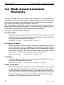
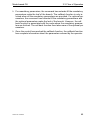
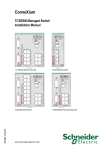
The parsing process is initiated whenever the operator types a command and
presses <ENTER>. The command tree is searched for the command of interest. If the command is not found, the output message indicates where the
offending entry begins. For instance, command node A has the command
"show spanning-tree" but the operator attempts to execute the command "show arpp brief" then the output message would be
(Schneider Product)(exec)> show sspanning-tree^. (Schneider Product)%Invalid input detected at '^' marker. If the
operator has given an invalid input parameter in the command, then the message conveys to the operator an invalid input was detected. The layout of the
output is depicted below:
(Schneider Product)(exec) #show sspanning-tree
^
(Schneider Product)Invalid input detected at '^' marker.
Fig. 2:
Syntax Error Message
After all the mandatory parameters are entered, any additional parameters
entered are treated as optional parameters. If any of the parameters are not
recognized a syntax error message will be displayed.
D After the command is successfully parsed and validated, the control of
execution goes to the corresponding CLI callback function.
44
31007130 - 03/2010
Mode-based CLI
3.3 Flow of Operation
D For mandatory parameters, the command tree extends till the mandatory
parameters make the leaf of the branch. The callback function is only invoked when all the mandatory parameters are provided. For optional parameters, the command tree extends till the mandatory parameters and
the optional parameters make the leaf of the branch. However, the call
back function is associated with the node where the mandatory parameters are fetched. The call back function then takes care of the optional parameters.
D Once the control has reached the callback function, the callback function
has complete information about the parameters entered by the operator.
31007130 - 03/2010
45
Mode-based CLI
3.4 “No” Form of a Command
3.4 “No” Form of a Command
“No” is a specific form of an existing command and does not represent a new
or distinct command. Only the configuration commands are available in the
“no” form. The behavior and the support details of the “no” form is captured
as part of the mapping sheets.
3.4.1 Support for “No” Form
Almost every configuration command has a “no” form. In general, use the no
form to reverse the action of a command or reset a value back to the default.
For example, the no shutdown interface configuration command reverses the shutdown of an interface. Use the command without the keyword
”no“ to re-enable a disabled feature or to enable a feature that is disabled by
default.
3.4.2 Behavior of Command Help ("?")
The “no” form is treated as a specific form of an existing command and does
not represent a new or distinct command. However, the behavior of the “?”
and help text differ for the “no” form (the help message shows only options
that apply to the “no” form).
D The help message is the same for all forms of the command. The help
string may be augmented with details about the “no” form behavior.
D For the (no interface?) and (no inte?) cases of the “?”, the options
displayed are identical to the case when the “no” token is not specified as
in (interface) and (inte?).
46
31007130 - 03/2010
CLI Commands: Base
4 CLI Commands: Base
This chapter provides detailed explanation of the Switching commands. The
commands are divided into five functional groups:
D Show commands display switch settings, statistics, and other information.
D Configuration commands configure features and options of the switch.
For every configuration command, there is a show command that displays
the configuration setting.
D Copy commands transfer or save configuration and informational files to
and from the switch.
D Clear commands clear
- some
(e.g. the ”clear arp-table-switch” command which clears the agent´s
ARP table) or
- all
(e.g. the ”clear config factory” command which resets the whole
configuration to the factory defaults).
This chapter includes the following configuration types:
D
D
D
D
D
D
D
D
D
D
System information and statistics commands
Management commands
Device configuration commands
User account management commands
Security commands
System utilities
Link Layer Discovery Protocol Commands
Simple Network Time Protocol Commands
Precision Time Protocol Commands
Power over Ethernet Commands
31007130 - 03/2010
47
CLI Commands: Base
4.1 System Information and Statistics Com-
4.1 System Information and
Statistics Commands
4.1.1 show address-conflict
This command displays address-conflict settings.
Format
show address-conflict
Mode
Privileged EXEC and User EXEC
4.1.2 show arp switch
This command displays the Address Resolution Protocol cache of the switch.
Format
show arp switch
Mode
Privileged EXEC and User EXEC
48
31007130 - 03/2010
CLI Commands: Base
4.1 System Information and Statistics Com-
4.1.3 show bridge address-learning
This command displays the address-learning setting.
The setting can be enable or disable.
Format
show bridge address-learning
Mode
Privileged EXEC and User EXEC
4.1.4 show bridge aging-time
This command displays the timeout for address aging.
Format
show bridge aging-time
Mode
Privileged EXEC and User EXEC
4.1.5 show bridge fast-link-detection
This command displays the Bridge Fast Link Detection setting.
Format
show bridge fast-link-detection
Mode
Privileged EXEC and User EXEC
31007130 - 03/2010
49
CLI Commands: Base
4.1 System Information and Statistics Com-
4.1.6 show bridge framesize
This command displays the maximum size of frame (packet size) setting.
Format
show bridge framesize
Mode
Privileged EXEC and User EXEC
4.1.7 show bridge vlan-learning
This command displays the bridge vlan-learning mode.
Format
show bridge vlan-learning
Mode
Privileged EXEC and User EXEC
50
31007130 - 03/2010
CLI Commands: Base
4.1 System Information and Statistics Com-
4.1.8 bridge framesize
Activation of long frames. Configure 1522 or 1632 as maximum size of frame
(packet size). Default: 1522.
Format
bridge framesize {1522|1632}
Mode
Global Config
bridge framesize 1522
Configure 1522 as maximum size of frame.
bridge framesize 1632
Configure 1632 as maximum size of frame.
4.1.9 show config-watchdog
Activating the watchdog enables you to return automatically to the last
configuration after a set time period has elapsed. This gives you back your
access to the Switch.
Format
show config-watchdog
Mode
Privileged EXEC and User EXEC
31007130 - 03/2010
51
CLI Commands: Base
4.1 System Information and Statistics Com-
4.1.10 show device-status
The signal device status is for displaying
D the monitoring functions of the switch,
D the device status trap setting.
Format
show device-status
[monitor|state|trap]
Mode
Privileged EXEC and User EXEC
Device status monitor
Displays the possible monitored events and which of them are
monitored:
– the detected failure of at least one of the supply voltages.
– the removal of the EAM
– the removal of a media module
– the temperature limits
– the defective link status of at least one port. With the switch, the
indication of link status can be masked by the management for each
port. Link status is not monitored in the delivery condition.
– the loss of Redundancy guarantee.
Ring/network coupling:
– The following conditions are reported in Stand-by mode:
– interrupted control line
– partner device running in Stand-by mode.
HIPER-Ring:
– The following condition is reported in RM mode additionally:
– Ring redundancy guaranteed. Ring redundancy is not monitored in
the delivery condition.
Device status state
Error The current device status is error.
No Error The current device status is no error.
Device status trap
enabled A trap is sent if the device status changes.
disabled No trap is sent if the device status changes.
52
31007130 - 03/2010
CLI Commands: Base
4.1 System Information and Statistics Com-
4.1.11 show authentication
This command displays users assigned to authentication login lists.
Format
show authentication [users <listname>]
Mode
Privileged EXEC and User EXEC
4.1.12 show classofservice
This command displays class of service settings.
Format
show classofservice dot1p-mapping [slot/port]
Mode
Privileged EXEC and User EXEC
slot/port
Valid slot and port number separated by forward slashes.
31007130 - 03/2010
53
CLI Commands: Base
4.1 System Information and Statistics Com-
4.1.13 show eventlog
This command displays the event log, which contains error messages from
the system. The event log is not cleared on a system reset.
Format
show eventlog
Mode
Privileged EXEC and User EXEC
File
The file in which the event originated.
Line
The line number of the event
Task Id
The task ID of the event.
Code
The event code.
Time
The time this event occurred.
Note: Event log information is retained across a switch reset.
54
31007130 - 03/2010
CLI Commands: Base
4.1 System Information and Statistics Com-
4.1.14 show interface
This command displays a summary of statistics for a specific port or a count
of all CPU traffic based upon the argument.
Format
show interface {<slot/port> | switchport}
Mode
Privileged EXEC and User EXEC
The display parameters, when the argument is ' <slot/port>', is as follows :
Packets Received Without Error
The total number of packets (including broadcast packets and multicast packets) received by the processor.
Packets Received With Error
The number of inbound packets that contained errors preventing
them from being deliverable to a higher-layer protocol.
Broadcast Packets Received
The total number of packets received that were directed to the broadcast address. Note that this does not include multicast packets.
Packets Transmitted Without Error
The total number of packets transmitted out of the interface.
Transmit Packets Errors
The number of outbound packets that could not be transmitted
because of errors.
Collisions Frames
The best estimate of the total number of collisions on this Ethernet
segment.
Time Since Counters Last Cleared
The elapsed time, in days, hours, minutes, and seconds since the statistics for this port were last cleared.
The display parameters, when the argument is 'switchport', is as follows :
Packets Received Without Error
The total number of packets (including broadcast packets and multicast packets) received by the processor.
31007130 - 03/2010
55
CLI Commands: Base
4.1 System Information and Statistics Com-
Broadcast Packets Received
The total number of packets received that were directed to the broadcast address. Note that this does not include multicast packets.
Packets Received With Error
The number of inbound packets that contained errors preventing
them from being deliverable to a higher-layer protocol.
Packets Transmitted Without Error
The total number of packets transmitted out of the interface.
Broadcast Packets Transmitted
The total number of packets that higher-level protocols requested to
be transmitted to the Broadcast address, including those that were
discarded or not sent.
Transmit Packet Errors
The number of outbound packets that could not be transmitted
because of errors.
Address Entries Currently In Use
The total number of Forwarding Database Address Table entries now
active on the switch, including learned and static entries.
VLAN Entries Currently In Use
The number of VLAN entries presently occupying the VLAN table.
Time Since Counters Last Cleared
The elapsed time, in days, hours, minutes, and seconds since the statistics for this switch were last cleared.
56
31007130 - 03/2010
CLI Commands: Base
4.1 System Information and Statistics Com-
4.1.15 show interface ethernet
This command displays detailed statistics for a specific port or for all CPU
traffic based upon the argument.
Format
show interface ethernet {<slot/port> | switchport}
Mode
Privileged EXEC and User EXEC
The display parameters, when the argument is '<slot/port>', are as follows :
Packets Received
Octets Received - The total number of octets of data (including those
in bad packets) received on the network (excluding framing bits but
including Frame Check Sequence (FCS) octets). This object can be
used as a reasonable estimate of ethernet utilization. If greater precision is desired, the etherStatsPkts and etherStatsOctets objects
should be sampled before and after a common interval. ----- The
result of this equation is the value Utilization which is the percent utilization of the ethernet segment on a scale of 0 to 100 percent.
Packets Received < 64 Octets - The total number of packets (including bad packets) received that were < 64 octets in length (excluding
framing bits but including FCS octets).
Packets Received 64 Octets - The total number of packets (including bad packets) received that were 64 octets in length (excluding
framing bits but including FCS octets).
Packets Received 65-127 Octets - The total number of packets
(including bad packets) received that were between 65 and 127
octets in length inclusive (excluding framing bits but including FCS
octets).
Packets Received 128-255 Octets - The total number of packets
(including bad packets) received that were between 128 and 255
octets in length inclusive (excluding framing bits but including FCS
octets).
Packets Received 256-511 Octets - The total number of packets
(including bad packets) received that were between 256 and 511
octets in length inclusive (excluding framing bits but including FCS
octets).
Packets Received 512-1023 Octets - The total number of packets
(including bad packets) received that were between 512 and 1023
31007130 - 03/2010
57
CLI Commands: Base
4.1 System Information and Statistics Com-
octets in length inclusive (excluding framing bits but including FCS
octets).
Packets Received 1024-1518 Octets - The total number of packets
(including bad packets) received that were between 1024 and 1518
octets in length inclusive (excluding framing bits but including FCS
octets).
Packets Received 1519-1522 Octets - The total number of packets
(including bad packets) received that were between 1519 and 1522
octets in length inclusive (excluding framing bits but including FCS
octets).
Packets Received > 1522 Octets - The total number of packets
received that were longer than 1522 octets (excluding framing bits,
but including FCS octets) and were otherwise well formed.
Packets Received Successfully
Total - The total number of packets received that were without errors.
Unicast Packets Received - The number of subnetwork-unicast
packets delivered to a higher-layer protocol.
Multicast Packets Received - The total number of good packets
received that were directed to a multicast address. Note that this
number does not include packets directed to the broadcast address.
Broadcast Packets Received - The total number of good packets
received that were directed to the broadcast address. Note that this
does not include multicast packets.
Packets Received with MAC Errors
Total - The total number of inbound packets that contained errors preventing them from being deliverable to a higher-layer protocol.
Jabbers Received - The total number of packets received that were
longer than 1518 octets (excluding framing bits, but including FCS
octets), and had either a bad Frame Check Sequence (FCS) with an
integral number of octets (FCS Error) or a bad FCS with a non-integral number of octets (Alignment Error). Note that this definition of
jabber is different than the definition in IEEE-802.3 section 8.2.1.5
(10BASE5) and section 10.3.1.4 (10BASE2). These documents
define jabber as the condition where any packet exceeds 20 ms. The
allowed range to detect jabber is between 20 ms and 150 ms.
Fragments/Undersize Received - The total number of packets
received that were less than 64 octets in length (excluding framing
bits but including FCS octets).
58
31007130 - 03/2010
CLI Commands: Base
4.1 System Information and Statistics Com-
Alignment Errors - The total number of packets received that had a
length (excluding framing bits, but including FCS octets) of between
64 and 1518 octets, inclusive, but had a bad Frame Check Sequence
(FCS) with a non-integral number of octets.
Rx FCS Errors - The total number of packets received that had a
length (excluding framing bits, but including FCS octets) of between
64 and 1518 octets, inclusive, but had a bad Frame Check Sequence
(FCS) with an integral number of octets
Overruns - The total number of frames discarded as this port was
overloaded with incoming packets, and could not keep up with the
inflow.
Received Packets not forwarded
Total - A count of valid frames received which were discarded (i.e. filtered) by the forwarding process.
Local Traffic Frames - The total number of frames dropped in the
forwarding process because the destination address was located off
of this port.
802.3x Pause Frames Received - A count of MAC Control frames
received on this interface with an opcode indicating the PAUSE operation. This counter does not increment when the interface is operating
in half-duplex mode.
Unacceptable Frame Type - The number of frames discarded from
this port due to being an unacceptable frame type.
VLAN Membership Mismatch - The number of frames discarded on
this port due to ingress filtering.
VLAN Viable Discards - The number of frames discarded on this
port when a lookup on a particular VLAN occurs while that entry in the
VLAN table is being modified, or if the VLAN has not been configured.
Multicast Tree Viable Discards - The number of frames discarded
when a lookup in the multicast tree for a VLAN occurs while that tree
is being modified.
Reserved Address Discards - The number of frames discarded that
are destined to an IEEE 802.1 reserved address and are not supported by the system.
Broadcast Storm Recovery - The number of frames discarded that
are destined for FF:FF:FF:FF:FF:FF when Broadcast Storm Recovery
is enabled.
CFI Discards - The number of frames discarded that have CFI bit set
and the addresses in RIF are in non-canonical format.
31007130 - 03/2010
59
CLI Commands: Base
4.1 System Information and Statistics Com-
Upstream Threshold - The number of frames discarded due to lack
of cell descriptors available for that packet's priority level.
Packets Transmitted Octets
Total Bytes - The total number of octets of data (including those in
bad packets) transmitted into the network (excluding framing bits but
including FCS octets). This object can be used as a reasonable estimate of ethernet utilization. If greater precision is desired, the etherStatsPkts and etherStatsOctets objects should be sampled before
and after a common interval. ----Packets Transmitted 64 Octets - The total number of packets
(including bad packets) transmitted that were 64 octets in length
(excluding framing bits but including FCS octets).
Packets Transmitted 65-127 Octets - The total number of packets
(including bad packets) transmitted that were between 65 and 127
octets in length inclusive (excluding framing bits but including FCS
octets).
Packets Transmitted 128-255 Octets - The total number of packets
(including bad packets) transmitted that were between 128 and 255
octets in length inclusive (excluding framing bits but including FCS
octets).
Packets Transmitted 256-511 Octets - The total number of packets
(including bad packets) transmitted that were between 256 and 511
octets in length inclusive (excluding framing bits but including FCS
octets).
Packets Transmitted 512-1023 Octets - The total number of packets
(including bad packets) transmitted that were between 512 and 1023
octets in length inclusive (excluding framing bits but including FCS
octets).
Packets Transmitted 1024-1518 Octets - The total number of packets (including bad packets) transmitted that were between 1024 and
1518 octets in length inclusive (excluding framing bits but including
FCS octets).
Packets Transmitted 1519-1522 Octets - The total number of packets (including bad packets) transmitted that were between 1519 and
1522 octets in length inclusive (excluding framing bits but including
FCS octets).
Max Info - The maximum size of the Info (non-MAC) field that this
port will receive or transmit.
60
31007130 - 03/2010
CLI Commands: Base
4.1 System Information and Statistics Com-
Packets Transmitted Successfully
Total - The number of frames that have been transmitted by this port
to its segment.
Unicast Packets Transmitted - The total number of packets that
higher-level protocols requested be transmitted to a subnetwork-unicast address, including those that were discarded or not sent.
Multicast Packets Transmitted - The total number of packets that
higher-level protocols requested be transmitted to a Multicast
address, including those that were discarded or not sent.
Broadcast Packets Transmitted - The total number of packets that
higher-level protocols requested be transmitted to the Broadcast
address, including those that were discarded or not sent.
Transmit Errors
Total Errors - The sum of Single, Multiple, and Excessive Collisions.
Tx FCS Errors - The total number of packets transmitted that had a
length (excluding framing bits, but including FCS octets) of between
64 and 1518 octets, inclusive, but had a bad Frame Check Sequence
(FCS) with an integral number of octets
Oversized - The total number of frames that exceeded the max permitted frame size. This counter has a max increment rate of 815
counts per sec. at 10 Mb/s.
Underrun Errors - The total number of frames discarded because
the transmit FIFO buffer became empty during frame transmission.
Transmit Discards
Total Discards - The sum of single collision frames discarded, multiple collision frames discarded, and excessive frames discarded.
Single Collision Frames - A count of the number of successfully
transmitted frames on a particular interface for which transmission is
inhibited by exactly one collision.
Multiple Collision Frames - A count of the number of successfully
transmitted frames on a particular interface for which transmission is
inhibited by more than one collision.
Excessive Collisions - A count of frames for which transmission on
a particular interface is discontinued due to excessive collisions.
Port Membership - The number of frames discarded on egress for
this port due to egress filtering being enabled.
VLAN Viable Discards - The number of frames discarded on this
port when a lookup on a particular VLAN occurs while that entry in the
VLAN table is being modified, or if the VLAN has not been configured.
31007130 - 03/2010
61
CLI Commands: Base
4.1 System Information and Statistics Com-
Protocol Statistics
BPDU's received - The count of BPDU's (Bridge Protocol Data Units)
received in the spanning tree layer.
BPDU's Transmitted - The count of BPDU's (Bridge Protocol Data
Units) transmitted from the spanning tree layer.
802.3x Pause Frames Received - A count of MAC Control frames
received on this interface with an opcode indicating the PAUSE operation. This counter does not increment when the interface is operating
in half-duplex mode.
GVRP PDU's Received - The count of GVRP PDU's received in the
GARP layer.
GMRP PDU's received - The count of GMRP PDU's received in the
GARP layer.
GMRP PDU's Transmitted - The count of GMRP PDU's transmitted
from the GARP layer.
GMRP Failed Registrations - The number of times attempted
GMRP registrations could not be completed.
STP BPDUs Transmitted - Spanning Tree Protocol Bridge Protocol
Data Units sent
STP BPDUs Received - Spanning Tree Protocol Bridge Protocol
Data Units received
RST BPDUs Transmitted - Rapid Spanning Tree Protocol Bridge
Protocol Data Units sent
RSTP BPDUs Received - Rapid Spanning Tree Protocol Bridge Protocol Data Units received
MSTP BPDUs Transmitted - Multiple Spanning Tree Protocol Bridge
Protocol Data Units sent
MSTP BPDUs Received - Multiple Spanning Tree Protocol Bridge
Protocol Data Units received
Dot1x Statistics
EAPOL Frames Received- The number of valid EAPOL frames of
any type that have been received by this authenticator.
EAPOL Frames Transmitted - The number of EAPOL frames of any
type that have been transmitted by this authenticator.
Time Since Counters Last Cleared
The elapsed time, in days, hours, minutes, and seconds since the statistics for this port were last cleared.
62
31007130 - 03/2010
CLI Commands: Base
4.1 System Information and Statistics Com-
The display parameters, when the argument is ‘switchport, are as follows :
Octets Received - The total number of octets of data received by the
processor (excluding framing bits but including FCS octets).
Total Packets Received Without Error- The total number of packets
(including broadcast packets and multicast packets) received by the
processor.
Unicast Packets Received - The number of subnetwork-unicast
packets delivered to a higher-layer protocol.
Multicast Packets Received - The total number of packets received
that were directed to a multicast address. Note that this number does
not include packets directed to the broadcast address.
Broadcast Packets Received - The total number of packets
received that were directed to the broadcast address. Note that this
does not include multicast packets.
Receive Packets Discarded - The number of inbound packets which
were chosen to be discarded even though no errors had been
detected to prevent their being deliverable to a higher-layer protocol.
A possible reason for discarding a packet could be to free up buffer
space.
Octets Transmitted - The total number of octets transmitted out of
the interface, including framing characters.
Packets Transmitted without Errors - The total number of packets
transmitted out of the interface.
Unicast Packets Transmitted - The total number of packets that
higher-level protocols requested be transmitted to a subnetwork-unicast address, including those that were discarded or not sent.
Multicast Packets Transmitted - The total number of packets that
higher-level protocols requested be transmitted to a Multicast
address, including those that were discarded or not sent.
Broadcast Packets Transmitted - The total number of packets that
higher-level protocols requested be transmitted to the Broadcast
address, including those that were discarded or not sent.
Transmit Packets Discarded - The number of outbound packets
which were chosen to be discarded even though no errors had been
detected to prevent their being deliverable to a higher-layer protocol.
A possible reason for discarding a packet could be to free up buffer
space.
Most Address Entries Ever Used - The highest number of Forwarding Database Address Table entries that have been learned by this
switch since the most recent reboot.
31007130 - 03/2010
63
CLI Commands: Base
4.1 System Information and Statistics Com-
Address Entries in Use - The number of Learned and static entries
in the Forwarding Database Address Table for this switch.
Maximum VLAN Entries - The maximum number of Virtual LANs
(VLANs) allowed on this switch.
Most VLAN Entries Ever Used - The largest number of VLANs that
have been active on this switch since the last reboot.
Static VLAN Entries - The number of presently active VLAN entries
on this switch that have been created statically.
Dynamic VLAN Entries - The number of presently active VLAN
entries on this switch that have been created by GVRP registration.
VLAN Deletes - The number of VLANs on this switch that have been
created and then deleted since the last reboot.
Time Since Counters Last Cleared
The elapsed time, in days, hours, minutes, and seconds, since the
statistics for this switch were last cleared.
64
31007130 - 03/2010
CLI Commands: Base
4.1 System Information and Statistics Com-
4.1.16 show interface switchport
This command displays data concerning the internal port to the management
agent.
Format
show interface switchport
Mode
Privileged EXEC and User EXEC
4.1.17 show logging
This command displays the trap log maintained by the switch. The trap log
contains a maximum of 256 entries that wrap.
Format
show logging [buffered | hosts | traplogs]
Mode
Privileged EXEC and User EXEC
buffered
Display buffered (in-memory) log entries.
hosts
Display logging hosts.
traplogs
Display trap records.
31007130 - 03/2010
65
CLI Commands: Base
4.1 System Information and Statistics Com-
4.1.18 show mac-addr-table
This command displays the forwarding database entries. If the command is
entered with no parameter, the entire table is displayed. This is the same as
entering the optional all parameter. Alternatively, the administrator can enter a MAC Address to display the table entry for the requested MAC address
and all entries following the requested MAC address.
Note: This command displays only learned unicast addresses. For other
addresses use the command show mac-filter-table.
Format
show mac-addr-table [<macaddr> | all]
Mode
Privileged EXEC and User EXEC
Mac Address
A unicast MAC address for which the switch has forwarding and or filtering
information. The format is 6 or 8 two-digit hexadecimal numbers that are
separated by colons, for example 01:23:45:67:89:AB.
Slot/Port
The port which this address was learned.
if Index
This object indicates the ifIndex of the interface table entry associated
with this port.
Status
The status of this entry. The meanings of the values are:
Learned The value of the corresponding instance was learned by
observing the source MAC addresses of incoming traffic, and is currently in use.
Management The value of the corresponding instance (system MAC
address) is also the value of an existing instance of
dot1dStaticAddress.
66
31007130 - 03/2010
CLI Commands: Base
4.1 System Information and Statistics Com-
4.1.19 show signal-contact
The signal contact is for displaying
D the manual setting and the current state of the signal contact,
D the monitoring functions of the switch,
D the signal-contacts trap setting.
Format
show signal-contact
[1|2|all [mode|monitor|state|trap]]
Mode
Privileged EXEC and User EXEC
Signal contact mode
Auto The signal contact monitors the functions of the switch which
makes it possible to perform remote diagnostics.
A break in contact is reported via the zero-potential signal contact
(relay contact, closed circuit).
Device Status The signal contact monitors the device-status.
Manual This command gives you the option of remote switching the
signal contact.
Signal contact monitor
Displays the possible monitored events and which of them are monitored:
– the detected failure of at least one of the supply voltages.
– the removal of a media module
– the temperature limits
– the defective link status of at least one port. With the switch, the
indication of link status can be masked by the management for each
port. Link status is not monitored in the delivery condition.
– the loss of Redundancy guarantee.
Ring/network coupling:
– The following conditions are reported in Stand-by mode:
– interrupted control line
– partner device running in Stand-by mode.
HIPER-Ring:
– The following condition is reported in RM mode additionally:
– Ring redundancy guaranteed. Ring redundancy is not monitored in
the delivery condition.
31007130 - 03/2010
67
CLI Commands: Base
4.1 System Information and Statistics Com-
Signal contact manual setting
closed The signal contact´s manual setting is closed.
open The signal contact´s manual setting is open.
Signal contact operating state
closed The signal contact is currently closed.
open The signal contact is currently open.
Signal contact trap
enabled A trap is sent if the signal contact state changes.
disabled No trap is sent if the signal contact state changes.
Note: To show the signal contact´s port related settings, use the command
show port {<slot/port> | all} (see “show port” on page 177).
4.1.20 show slot
This command is used to display information about slot(s).
For [slot] enter the slot ID.
Format
show slot [slot]
Mode
Privileged EXEC
4.1.21 show running-config
This command is used to display the current setting of different protocol
packages supported on the switch. This command displays only those
parameters, the values of which differ from default value. The output is
68
31007130 - 03/2010
CLI Commands: Base
4.1 System Information and Statistics Com-
displayed in the script format, which can be used to configure another switch
with the same configuration.
Format
show running-config [all | <scriptname>]
Mode
Privileged EXEC
all
Show all the running configuration on the switch. All configuration
parameters will be output even if their value is the default value.
<scriptname>
Script file name for writing active configuration.
Note: file extension must be .cli, file name must not exceed 16 characters, must not start with a dot (.) and must not contain a directory.
31007130 - 03/2010
69
CLI Commands: Base
4.1 System Information and Statistics Com-
4.1.22 show sysinfo
This command displays switch information.
Format
show sysinfo
Mode
Privileged EXEC and User EXEC
Alarm
Displays the latest present Alarm for a signal contact.
System Description
Text used to identify this switch.
System Name
Name used to identify the switch.
System Location
Text used to identify the location of the switch. May be up to 31 alphanumeric characters. The factory default is blank.
System Contact
Text used to identify a contact person for this switch. May be up to 31
alpha-numeric characters. The factory default is blank.
System Up Time
The time in days, hours and minutes since the last switch reboot.
System Date and Time
The system clock´s date and time in local time zone.
System IP Address
The system´s IP address.
Boot Software Release
The boot code´s version number.
Boot Software Build Date
The boot code´s build date.
Operating system Software Release
The operating system´s software version number.
Operating system Software Build Date
The operating system´s software build date.
70
31007130 - 03/2010
CLI Commands: Base
4.1 System Information and Statistics Com-
Backplane Hardware Revision
The hardware´s revision number.
Backplane Hardware Description
The hardware´s device description.
Serial Number (Backplane)
The hardware´s serial number.
Base MAC Address (Backplane)
The hardware´s base MAC address.
Number of MAC Addresses (Backplane)
The number of hardware MAC addresses.
Configuration state
The state of the actual configuration.
Memory Backup Adapter, State
The Menory Backup Adapter's state.
Memory Backup Adapter, Serial Number
The Memory Backup Adapter's serial number (if present and
operative).
Power Supply Information
The status of the power supplies.
CPU Utilization
The utilization of the central processing unit.
Flashdisk
Free memory on flashdisk (in Kbytes).
31007130 - 03/2010
71
CLI Commands: Base
4.1 System Information and Statistics Com-
4.1.23 show temperature
This command displays the lower and upper temperature limit for sending a
trap.
Format
show temperature
Mode
Privileged EXEC and User EXEC
4.1.24 snmp-server
This command sets the name and the physical location of the switch, and the
organization responsible for the network.The range for name, location and
contact is from 0 to 64 alphanumeric characters.
Default
None
Format
snmp-server {sysname <name> | location <loc> | contact <con>}
Mode
Global Config
72
31007130 - 03/2010
CLI Commands: Base
4.2 Management VLAN Commands
4.2 Management VLAN Commands
4.2.1 network mgmt_vlan
This command configures the Management VLAN ID. If you enter the VLAN
ID “0” , the agent can be accessed by all VLANs.
Default
1
Format
network mgmt_vlan <0-4042>
Mode
Privileged EXEC
31007130 - 03/2010
73
CLI Commands: Base
4.3 Class of Service (CoS) Commands
4.3 Class of Service (CoS)
Commands
This chapter provides a detailed explanation of the QoS CoS commands.
The following commands are available.
The commands are divided into these different groups:
D Configuration Commands are used to configure features and options of
the switch. For every configuration command there is a show command
that will display the configuration setting.
D Show commands are used to display device settings, statistics and other
information.
Note: The 'Interface Config' mode only affects a single interface, whereas the
'Global Config' mode is applied to all interfaces.
74
31007130 - 03/2010
CLI Commands: Base
4.3 Class of Service (CoS) Commands
4.3.1 classofservice dot1p-mapping
This command maps an 802.1p priority to an internal traffic class for a device
when in ‘Global Config’ mode. The number of available traffic classes may
vary with the platform. Userpriority and trafficclass can both be the range
from 0-7. The command is only available on platforms that support priority to
traffic class mapping on a ‘per-port’ basis, and the number of available traffic
classes may vary with the platform.
Format
classofservice dot1p-mapping <userpriority> <trafficclass>
Mode
Global Config or Interface Config
U no classofservice dot1p-mapping
This command restores the default mapping of the 802.1p priority to an
internal traffic class.
Format
no classofservice dot1p-mapping
Modes
Global Config or Interface Config
31007130 - 03/2010
75
CLI Commands: Base
4.3 Class of Service (CoS) Commands
4.3.2 classofservice ip-dscp-mapping
This command maps an IP DSCP value to an internal traffic class.
The <ipdscp> value is specified as either an integer from 0 to 63, or
symbolically through one of the following keywords: af11, af12, af13, af21,
af22, af23, af31, af32, af33, af41, af42, af43, be, cs0, cs1, cs2, cs3, cs4, cs5,
cs6, cs7, ef.
Format
classofservice ip-dscp-mapping <ipdscp> <trafficclass>
Mode
Global Config
U no classofservice ip-dscp-mapping
This command restores the default mapping of the IP DSCP value to an
internal traffic class.
Format
no classofservice dot1p-mapping
Modes
Global Config
76
31007130 - 03/2010
CLI Commands: Base
4.3 Class of Service (CoS) Commands
4.3.3 classofservice trust
This command sets the class of service trust mode of an interface. The mode
can be set to trust one of the Dot1p (802.1p) or IP DSCP packet markings.
Note: In trust ip-dscp mode the switch modifies the vlan priority for outgoing frames according to
– the a fix mapping table
(see Reference Manual ”Web-based Management” for further details).
Format
classofservice trust dot1p | <ip-dscp>
Mode
Global Config or
U no classofservice trust
This command sets the interface mode to untrusted, i.e. the packet priority marking is ignored and the default port priority is used instead.
Format
no classofservice trust
Modes
Global Config or
31007130 - 03/2010
77
CLI Commands: Base
4.3 Class of Service (CoS) Commands
4.3.4 show classofservice dot1p-mapping
This command displays the current 802.1p priority mapping to internal traffic
classes for a specific interface. The slot/port parameter is required on
platforms that support priority to traffic class mapping on a ‘per-port’ basis.
Platforms that support priority to traffic class mapping on a per-port basis:
Format
show classofservice dot1p-mapping [<slot/port>]
Platforms that do not support priority to traffic class mapping on a per-port
basis:
Format
show classofservice dot1p-mapping
Mode
Privileged EXEC and User EXEC
78
31007130 - 03/2010
CLI Commands: Base
4.3 Class of Service (CoS) Commands
4.3.5 show classofservice ip-dscp-mapping
This command displays the current IP DSCP mapping to internal traffic classes for the global configuration settings.
Format
show classofservice ip-dscp-mapping
Mode
Privileged EXEC
The following information is repeated for each user priority.
IP DSCP
The IP DSCP value.
Traffic Class
The traffic class internal queue identifier to which the IP DSCP value
is mapped.
31007130 - 03/2010
79
CLI Commands: Base
4.3 Class of Service (CoS) Commands
4.3.6 show classofservice trust
This command displays the current trust mode for the specified interface.
The slot/port parameter is optional. If specified, the trust mode of the interface is displayed. If omitted, the most recent global configuration settings are
displayed.
Format
show classofservice trust [slot/port]
Mode
Privileged EXEC
Class of Service Trust Mode
The current trust mode: Dot1p, IP DSCP, or Untrusted.
Untrusted Traffic Class
The traffic class used for all untrusted traffic. This is only displayed
when the COS trust mode is set to 'untrusted'.
80
31007130 - 03/2010
CLI Commands: Base
4.3 Class of Service (CoS) Commands
4.3.7 vlan port priority all
This command configures the port priority assigned for untagged packets for
all ports presently plugged into the device. The range for the priority is 0-7.
Any subsequent per port configuration will override this configuration setting.
Format
vlan port priority all <priority>
Mode
Global Config
4.3.8 vlan priority
This command configures the default 802.1p port priority assigned for untagged packets for a specific interface. The range for the priority is 0-7
Default
0
Format
vlan priority <priority>
Mode
Interface Config
31007130 - 03/2010
81
CLI Commands: Base
4.4 Management Commands
4.4 Management Commands
These commands manage the switch and show current management
settings.
4.4.1 transport input telnet
This command regulates new telnet sessions. If sessions are enabled, new
telnet sessions can be established until there are no more sessions
available. If sessions are disabled, no new telnet sessions are established.
An established session remains active until the session is ended or an
abnormal network error ends the session.
Default
enabled
Format
transport input telnet
Mode
Line Config
U no transport input telnet
This command disables telnet sessions. If sessions are disabled, no new
telnet sessions are established.
Format
no transport input telnet
Mode
Line Config
82
31007130 - 03/2010
CLI Commands: Base
4.4 Management Commands
4.4.2 bridge address-learning
To enable you to observe the data at all the ports, the Switch allows you to
disable the learning of addresses. When the learning of addresses is disabled, the Switch transfers all the data from all ports to all ports. The default
value is enable.
Format
bridge address-learning {disable|enable}
Mode
Global Config
31007130 - 03/2010
83
CLI Commands: Base
4.4 Management Commands
4.4.3 bridge aging-time
This command configures the forwarding database address aging timeout in
seconds.
Default
30
Format
bridge aging-time <15-3825>
Mode
Global Config
Seconds
The <seconds> parameter must be within the range of 10 to 630 seconds.
U no bridge aging-time
This command sets the forwarding database address aging timeout to
30 seconds.
Format
no bridge aging-time
Mode
Global Config
84
31007130 - 03/2010
CLI Commands: Base
4.4 Management Commands
4.4.4 bridge fast-link-detection
This command enables or disables the Bridge Fast Link Detection.
Default
Enabled
Format
bridge fast-link-detection {disable|enable}
Mode
Global Config
4.4.5 bridge vlan-learning
With ”independent” you set the Shared VLAN Learning mode to Independent. The switch will treat equal MAC source addresses from different VLANs
as separate addresses.
With ”shared” you set the Shared VLAN Learning mode to Shared. The
switch will treat equal MAC source addresses from different VLANs as the
same adress.
Format
bridge vlan-learning {independent|shared}
Mode
Global Config
4.4.6 ethernet-ip
This command controls the EtherNet/IP function on the switch.
Detailed information you can find in the User Manual Industrial Protocols.
31007130 - 03/2010
85
CLI Commands: Base
4.4 Management Commands
Default
depends on the order code (standard = disable)
Format
ethernet-ip admin-state {enable | disable}
Mode
Global Config
Admin-state
disable Disables the EtherNet/IP function on this device.
Note: the relevant MIB objects are still accessible.
enable Enables the EtherNet/IP function on this device.
4.4.7 network javascriptmode
When the user accesses the switch’s web interface, the switch’s web server
will deliver a HTML page that contains JavaScript.
Default
enabled
Format
network javascriptmode
Mode
Privileged EXEC
U no network javascriptmode
When the user accesses the switch’s web interface, the switch’s web
server will deliver a HTML page that contains no JavaScript.
Format
no network javamode
Mode
Privileged EXEC
86
31007130 - 03/2010
CLI Commands: Base
4.4 Management Commands
4.4.8 network parms
This command sets the IP Address, subnet mask and gateway of the router.
The IP Address and the gateway must be on the same subnet.
Format
network parms <ipaddr> <netmask> [gateway]
Mode
Privileged EXEC
4.4.9 network protocol
This command specifies the network configuration protocol to be used. If you
modify this value change is effective immediately. The parameter bootp indicates that the switch periodically sends requests to a Bootstrap Protocol
(BootP) server or a DHCP server until a response is received. none indicates
that the switch should be manually configured with IP information.
Independently of the BootP and DHCP settings, Ethernet Switch Configurator Software can be configured as an additional protocol.
Default
DHCP
Format
network protocol {none | bootp | dhcp | ethernetswitch-conf {off | read-only | read-write}}
Mode
Privileged EXEC
31007130 - 03/2010
87
CLI Commands: Base
4.4 Management Commands
4.4.10 network priority
This command configures the VLAN priority or the IP DSCP value for outgoing management packets. The <ipdscp> is specified as either an integer
from 0-63, or symbolically through one of the following keywords:
af11,af12,af13,af21,af22,af23,af31,af32,af33,af41,af42,af43,be,cs0, cs1,
cs2,cs3,cs4,cs5,cs6,cs7,ef.
Default
0 for both values
Format
network priority {dot1p-vlan <0-7> |
ip-dscp <ipdscp> }
Mode
Privileged EXEC
U no network priority
This command sets the VLAN priority or the IP DSCP value for outgoing
management packets to default which means VLAN priority 0 or
IP DSCP value 0 (Best effort).
Format
no network priority {dot1p-vlan | ip-dscp }
Mode
Privileged EXEC
88
31007130 - 03/2010
CLI Commands: Base
4.4 Management Commands
4.4.11 serial timeout
This command specifies the maximum connect time (in minutes) without
console activity. A value of 0 indicates that a console can be connected indefinitely. The time range is 0 to 160.
Default
5
Format
serial timeout <0-160>
Mode
Line Config
U no serial timeout
This command sets the maximum connect time without console activity
(in minutes) back to the default value.
Format
no serial timeout
Mode
Line Config
31007130 - 03/2010
89
CLI Commands: Base
4.4 Management Commands
4.4.12 set prompt
This command changes the name of the prompt. The length of name may be
up to 64 alphanumeric characters.
Format
set prompt <prompt string>
Mode
Privileged EXEC
4.4.13 show ethernet-ip
This command displays the admin state of the EtherNet/IP function.
Format
show ethernet-ip
Mode
Privileged EXEC and User EXEC
90
31007130 - 03/2010
CLI Commands: Base
4.4 Management Commands
4.4.14 show network
This command displays configuration settings associated with the switch's
network interface. The network interface is the logical interface used for inband connectivity with the switch via any of the switch's front panel ports.
The configuration parameters associated with the switch's network interface
do not affect the configuration of the front panel ports through which traffic is
switched or routed.
Format
show network
Mode
Privileged EXEC and User EXEC
IP Address
The IP address of the interface. The factory default value is 0.0.0.0
Subnet Mask
The IP subnet mask for this interface. The factory default value is
0.0.0.0
Default Gateway
The default gateway for this IP interface. The factory default value is
0.0.0.0
Burned In MAC Address
The burned in MAC address used for in-band connectivity.
Network Configuration Protocol (BootP/DHCP)
Indicates which network protocol is being used. The options are
bootp | dhcp | none.
DHCP Client ID (same as SNMP System Name)
Displays the DHCP Client ID.
Network Configuration Protocol Ethernet Switch Configurator Software
Indicates in which way the Ethernet Switch Configurator Software
protocol is being used. The options are off | read-only |
read-write.
Management VLAN ID
Specifies the management VLAN ID.
Management VLAN Priority
Specifies the management VLAN Priority.
31007130 - 03/2010
91
CLI Commands: Base
4.4 Management Commands
Management VLAN IP-DSCP Value
Specifies the management VLAN IP-DSCP value.
Java Script Mode
Specifies if the Switch will use Java Script to start the Management
Applet. The factory default is enabled.
4.4.15 show serial
This command displays serial communication settings for the switch.
Format
show serial
Mode
Privileged EXEC and User EXEC
Serial Port Login Timeout (minutes)
Specifies the time, in minutes, of inactivity on a Serial port connection,
after which the Switch will close the connection. Any numeric value
between 0 and 160 is allowed, the factory default is 5. A value of 0
disables the timeout.
92
31007130 - 03/2010
CLI Commands: Base
4.4 Management Commands
4.4.16 show snmp-access
This command displays SNMP access information related to global and
SNMP version settings. SNMPv3 is always enabled.
Format
show snmp-access
Mode
Privileged EXEC and User EXEC
4.4.17 show snmpcommunity
This command displays SNMP community information. Six communities are
supported. You can add, change, or delete communities. The switch does
not have to be reset for changes to take effect.
The SNMP agent of the switch complies with SNMP Version 1 (for more
about the SNMP specification, see the SNMP RFCs). The SNMP agent
sends traps through TCP/IP to an external SNMP manager based on the
SNMP configuration (the trap receiver and other SNMP community
parameters).
Format
show snmpcommunity
Mode
Privileged EXEC
SNMP Community Name
The community string to which this entry grants access. A valid entry
is a case-sensitive alphanumeric string of up to 32 characters. Each
row of this table must contain a unique community name.
Client IP Address An IP address (or portion thereof) from which this device will accept
SNMP packets with the associated community. The requesting
entity's IP address is ANDed with the Subnet Mask before being compared to the IP Address. Note: that if the Subnet Mask is set to
31007130 - 03/2010
93
CLI Commands: Base
4.4 Management Commands
0.0.0.0, an IP Address of 0.0.0.0 matches all IP addresses. The
default value is 0.0.0.0
Client IP Mask A mask to be ANDed with the requesting entity's IP address before
comparison with IP Address. If the result matches with IP Address
then the address is an authenticated IP address. For example, if the
IP Address = 9.47.128.0 and the corresponding Subnet Mask =
255.255.255.0 a range of incoming IP addresses would match, i.e.
the incoming IP Address could equal 9.47.128.0 - 9.47.128.255. The
default value is 0.0.0.0
Access Mode
The access level for this community string.
Status
The status of this community access entry.
94
31007130 - 03/2010
CLI Commands: Base
4.4 Management Commands
4.4.18 show snmptrap
This command displays SNMP trap receivers. Trap messages are sent
across a network to an SNMP Network Manager. These messages alert the
manager to events occurring within the switch or on the network. Six trap receivers are simultaneously supported.
Format
show snmptrap
Mode
Privileged EXEC and User EXEC
SNMP Trap Name
The community string of the SNMP trap packet sent to the trap manager. This may be up to 32 alphanumeric characters. This string is
case sensitive.
IP Address
The IP address to receive SNMP traps from this device. Enter four
numbers between 0 and 255 separated by periods.
Status
A pull down menu that indicates the receiver's status (enabled or disabled) and allows the administrator/user to perform actions on this
user entry:
Enable - send traps to the receiver
Disable - do not send traps to the receiver.
Delete - remove the table entry.
31007130 - 03/2010
95
CLI Commands: Base
4.4 Management Commands
4.4.19 show telnetcon
This command displays inbound telnet settings.
Format
show telnetcon
Mode
Privileged EXEC and User EXEC
Telnet Connection Login Timeout (minutes)
This object indicates the number of minutes a remote connection session is allowed to remain inactive before being logged off. May be
specified as a number from 1 to 160. The factory default is 4.
Maximum Number of Remote Telnet Sessions
This object indicates the number of simultaneous remote connection
sessions allowed. The factory default is 2 (4 for version L2P)
Allow New Telnet Sessions
Indicates that new telnet sessions will not be allowed when set to no.
The factory default value is yes.
96
31007130 - 03/2010
CLI Commands: Base
4.4 Management Commands
4.4.20 show trapflags
This command displays trap conditions. Configure which traps the switch
should generate by enabling or disabling the trap condition. If a trap condition
is enabled and the condition is detected, the switch's SNMP agent sends the
trap to all enabled trap receivers. The switch does not have to be reset to implement the changes. Cold and warm start traps are always generated and
cannot be disabled.
Format
show trapflags
Mode
Privileged EXEC and User EXEC
Authentication Flag
May be enabled or disabled. The factory default is enabled. Indicates
whether authentication failure traps will be sent.
Chassis
Indicates whether traps that are related to the chassis functionality of
the switch will be sent. These functions include the signal contacts,
the EAM, temperature limits exceeded, status of power supply has
changed and the LLDP and SNTP features. May be enabled or disabled.
Default: enabled.
Layer 2 Redundancy
Indicates whether traps that are related to the layer 2 redundancy
features of the switch will be sent. The HiPER-Ring and the
Redundant Coupling will tell you with these traps when the main line
has become inoperative or returned. May be enabled or disabled.
Default: enabled.
Link Up/Down Flag
May be enabled or disabled. The factory default is enabled. Indicates
whether link status traps will be sent.
Multiple Users Flag
May be enabled or disabled. The factory default is enabled. Indicates
whether a trap will be sent when the same user ID is logged into the
switch more than once at the same time (either via telnet or serial
port).
31007130 - 03/2010
97
CLI Commands: Base
4.4 Management Commands
Port Security (MAC, IP and 802.1X
Enable/disable sending port security event traps (for MAC/IP port
security as well as for 802.1X).
Spanning Tree Flag
May be enabled or disabled. The factory default is enabled. Indicates
whether spanning tree traps will be sent.
4.4.21 snmp-access global
This command configures the global SNMP access setting (for all SNMP
versions).
Format
snmp-access global {disable|enable|read-only}
Mode
Global Config
disable
Disable SNMP access to this switch, regardless of the SNMP version
used.
enable
Enable SNMP read and write access to this switch, regardless of the
SNMP version used.
read-only
Enable SNMP read-only access to this switch (disable write access),
regardless of the SNMP version used.
98
31007130 - 03/2010
CLI Commands: Base
4.4 Management Commands
4.4.22 snmp-access version
This command configures the SNMP version specific access mode for
SNMPv1 and SNMPv2.
Format
snmp-access version {all|v1|v2} {disable|enable}
Mode
Global Config
all
Enable or disable SNMP access by all protocol versions (v1 and v2).
v1
Enable or disable SNMP access by v1.
v2
Enable or disable SNMP access by v2.
Note: The SNMPv3 is always allowed and can only be disabled or restricted
by the global command (snmp-access global ...).
31007130 - 03/2010
99
CLI Commands: Base
4.4 Management Commands
4.4.23 snmp-server community
This command adds a new SNMP community name. A community name is
a name associated with the switch and with a set of SNMP managers that
manage it with a specified privileged level. The length of name can be up to
32 case-sensitive characters.
Note: Community names in the SNMP community table must be unique.
When making multiple entries using the same community name, the first
entry is kept and processed and all duplicate entries are ignored.
Default
Two default community names: Public and Private. You can replace
these default community names with unique identifiers for each community. The default values for the remaining four community names
are blank.
Format
snmp-server community <name>
Mode
Global Config
U no snmp-server community
This command removes this community name from the table. The name
is the community name to be deleted.
Format
no snmp-server community <name>
Mode
Global Config
100
31007130 - 03/2010
CLI Commands: Base
4.4 Management Commands
4.4.24 snmp-server community ipaddr
This command sets a client IP address for an SNMP community. The address is the associated community SNMP packet sending address and is
used along with the client IP mask value to denote a range of IP addresses
from which SNMP clients may use that community to access the device. A
value of 0.0.0.0 allows access from any IP address. Otherwise, this value is
ANDed with the mask to determine the range of allowed client IP addresses.
The name is the applicable community name.
Default
0.0.0.0
Format
snmp-server community ipaddr <ipaddr> <name>
Mode
Global Config
U no snmp-server community ipaddr
This command sets a client IP address for an SNMP community to
0.0.0.0. The name is the applicable community name.
Format
no snmp-server community ipaddr <name>
Mode
Global Config
31007130 - 03/2010
101
CLI Commands: Base
4.4 Management Commands
4.4.25 snmp-server community ipmask
This command sets a client IP mask for an SNMP community. The address
is the associated community SNMP packet sending address and is used
along with the client IP address value to denote a range of IP addresses from
which SNMP clients may use that community to access the device. A value
of 255.255.255.255 will allow access from only one station, and will use that
machine's IP address for the client IP Address. A value of 0.0.0.0 will allow
access from any IP address. The name is the applicable community name.
Default
0.0.0.0
Format
snmp-server community ipmask <ipmask> <name>
Mode
Global Config
U no snmp-server community ipmask
This command sets a client IP mask for an SNMP community to 0.0.0.0.
The name is the applicable community name. The community name may
be up to 32 alphanumeric characters.
Format
no snmp-server community ipmask <name>
Mode
Global Config
102
31007130 - 03/2010
CLI Commands: Base
4.4 Management Commands
4.4.26 snmp-server community mode
This command activates an SNMP community. If a community is enabled, an
SNMP manager associated with this community manages the switch according to its access right. If the community is disabled, no SNMP requests using
this community are accepted. In this case the SNMP manager associated
with this community cannot manage the switch until the Status is changed
back to Enable.
Default
The default private and public communities are enabled by default.
The four undefined communities are disabled by default.
Format
snmp-server community mode <name>
Mode
Global Config
U no snmp-server community mode
This command deactivates an SNMP community. If the community is
disabled, no SNMP requests using this community are accepted. In this
case the SNMP manager associated with this community cannot
manage the switch until the Status is changed back to Enable.
Format
no snmp-server community mode <name>
Mode
Global Config
31007130 - 03/2010
103
CLI Commands: Base
4.4 Management Commands
4.4.27 snmp-server community ro
This command restricts access to switch information. The access mode is
read-only (also called public).
Format
snmp-server community ro <name>
Mode
Global Config
4.4.28 snmp-server community rw
This command restricts access to switch information. The access mode is
read/write (also called private).
Format
snmp-server community rw <name>
Mode
Global Config
4.4.29 snmp-server location
This command configures the system location.
Format
snmp-server location <system location>
Mode
Global Config
104
31007130 - 03/2010
CLI Commands: Base
4.4 Management Commands
4.4.30 snmp-server sysname
This command configures the system name.
Format
snmp-server sysname <system name>
Mode
Global Config
31007130 - 03/2010
105
CLI Commands: Base
4.4 Management Commands
4.4.31 snmp-server enable traps
This command enables the Authentication Trap Flag.
Default
enabled
Format
snmp-server enable traps
Mode
Global Config
U no snmp-server enable traps
This command disables the Authentication Trap Flag.
Format
no snmp-server enable traps
Mode
Global Config
106
31007130 - 03/2010
CLI Commands: Base
4.4 Management Commands
4.4.32 snmp-server enable traps chassis
Configures whether traps that are related to the chassis functionality of the
switch will be sent. These functions include the signal contacts, the EAM,
temperature limits exceeded, status of power supply has changed and the
LLDP and SNTP features. May be enabled or disabled.
Default: enabled.
Default
enabled
Format
snmp-server enable traps chassis
Mode
Global Config
U no snmp-server enable traps chassis
This command disables chassis traps for the entire switch.
Format
no snmp-server enable traps chassis
Mode
Global Config
31007130 - 03/2010
107
CLI Commands: Base
4.4 Management Commands
4.4.33 snmp-server enable traps l2redundancy
Indicates whether traps that are related to the layer 2 redundancy features of
the switch will be sent. The HiPER-Ring and the Redundant Coupling will tell
you with these traps when the main line has become inoperative or returned.
May be enabled or disabled.
Default: enabled.
Default
enabled
Format
snmp-server enable traps l2redundancy
Mode
Global Config
U no snmp-server enable traps l2redundancy
This command disables layer 2 redundancy traps for the entire switch.
Format
no snmp-server enable traps l2redundancy
Mode
Global Config
108
31007130 - 03/2010
CLI Commands: Base
4.4 Management Commands
4.4.34 snmp-server enable traps linkmode
This command enables Link Up/Down traps for the entire switch. When enabled, link traps are sent only if the Link Trap flag setting associated with the
port is enabled (see ‘snmp trap link-status’ command).
Default
enabled
Format
snmp-server enable traps linkmode
Mode
Global Config
U no snmp-server enable traps linkmode
This command disables Link Up/Down traps for the entire switch.
Format
no snmp-server enable traps linkmode
Mode
Global Config
31007130 - 03/2010
109
CLI Commands: Base
4.4 Management Commands
4.4.35 snmp-server enable traps multiusers
This command enables Multiple User traps. When the traps are enabled, a
Multiple User Trap is sent when a user logs in to the terminal interface (EIA
232 (serial port) or telnet) and there is an existing terminal interface session.
Default
enabled
Format
snmp-server enable traps multiusers
Mode
Global Config
U no snmp-server enable traps multiusers
This command disables Multiple User traps.
Format
no snmp-server enable traps multiusers
Mode
Global Config
110
31007130 - 03/2010
CLI Commands: Base
4.4 Management Commands
4.4.36 snmp-server enable traps port-sec
This command enables port security traps. When the traps are enabled, a
Port Security Trap is sent if a port security event occurs
(applies to MAC/IP Port Security as well as to 802.1X Port Security.
Default
enabled
Format
snmp-server enable traps port-sec
Mode
Global Config
U no snmp-server enable traps port-sec
This command disables Port Security traps.
Format
no snmp-server enable traps port-sec
Mode
Global Config
31007130 - 03/2010
111
CLI Commands: Base
4.4 Management Commands
4.4.37 snmp-server enable traps stpmode
This command enables the sending of new root traps and topology change
notification traps.
Default
enabled
Format
snmp-server enable traps stpmode
Mode
Global Config
U no snmp-server enable traps stpmode
This command disables the sending of new root traps and topology
change notification traps.
Format
no snmp-server enable traps stpmode
Mode
Global Config
112
31007130 - 03/2010
CLI Commands: Base
4.4 Management Commands
4.4.38 snmptrap
This command adds an SNMP trap name. The maximum length of name is
32 case-sensitive alphanumeric characters.
Default
The default name for the six undefined community names is Delete.
Format
snmptrap <name> <ipaddr> [snmpversion snmpv1]
Mode
Global Config
U no snmptrap
This command deletes trap receivers for a community.
Format
no snmptrap <name> <ipaddr>
Mode
Global Config
31007130 - 03/2010
113
CLI Commands: Base
4.4 Management Commands
4.4.39 snmptrap ipaddr
This command assigns an IP address to a specified community name. The
maximum length of name is 32 case-sensitive alphanumeric characters.
Note: IP addresses in the SNMP trap receiver table must be unique. If you
make multiple entries using the same IP address, the first entry is retained
and processed. All duplicate entries are ignored.
Format
snmptrap ipaddr <name> <ipaddr> <ipaddrnew>
Mode
Global Config
ipaddr
Enter the old IP Address.
ipaddrnew
Enter the new IP Address.
114
31007130 - 03/2010
CLI Commands: Base
4.4 Management Commands
4.4.40 snmptrap mode
This command activates or deactivates an SNMP trap. Enabled trap receivers are active (able to receive traps). Disabled trap receivers are inactive (not
able to receive traps).
Format
snmptrap mode <name> <ipaddr>
Mode
Global Config
U no snmptrap mode
This command deactivates an SNMP trap. Disabled trap receivers are
inactive (not able to receive traps).
Format
no snmptrap mode <name> <ipaddr>
Mode
Global Config
31007130 - 03/2010
115
CLI Commands: Base
4.4 Management Commands
4.4.41 snmptrap snmpversion
This command configures SNMP trap version for a specified community.
Format
snmptrap snmpversion <name> <ipAddr>
{snmpv1 | snmpv2}
Mode
Global Config
name
Enter the community name.
ipAaddr
Enter the IP Address.
snmpv1
Use SNMP v1 to send traps.
snmpv2
Use SNMP v2 to send traps.
116
31007130 - 03/2010
CLI Commands: Base
4.4 Management Commands
4.4.42 telnetcon maxsessions
Configure the number of remote telnet connections allowed.
Default
5
Format
telnetcon maxsessions <0-5>
Mode
Privileged EXEC
U no telnetcon maxsessions
This command sets the maximum number of telnet connection sessions
that can be established to the default value.
Format
no telnetcon maxsessions
Mode
Privileged EXEC
31007130 - 03/2010
117
CLI Commands: Base
4.4 Management Commands
4.4.43 telnetcon timeout
This command sets the telnet connection session timeout value, in minutes.
A session is active as long as the session has not been idle for the value set.
The time is a decimal value from 1 to 160.
Default
5
Format
telnetcon timeout <1-160>
Mode
Privileged EXEC
U no telnetcon timeout
This command sets the telnet connection session timeout value to the
default.
Changing the timeout value for active sessions does not become effective until the session is reaccessed. Also, any keystroke activates the
new timeout duration.
Format
no telnetcon timeout
Mode
Privileged EXEC
118
31007130 - 03/2010
CLI Commands: Base
4.5 Syslog Commands
4.5 Syslog Commands
This section provides a detailed explanation of the Syslog commands. The
commands are divided into two functional groups:
D Show commands display spanning tree settings, statistics, and other information.
D Configuration Commands configure features and options of the device.
For every configuration command there is a show command that displays
the configuration setting.
4.5.1 logging buffered
This command enables logging to an in-memory log where up to 128 logs are
kept.
Default
enabled
Format
logging buffered
Mode
Global Config
U no logging buffered
This command disables logging to in-memory log.
Format
no logging buffered
31007130 - 03/2010
119
CLI Commands: Base
4.5 Syslog Commands
4.5.2 logging buffered wrap
This command enables wrapping of in-memory logging when full capacity
reached. Otherwise when full capacity is reached, logging stops.
Default
wrap
Format
logging buffered wrap
Mode
Privileged EXEC
U no logging buffered wrap
This command disables wrapping of in-memory logging and
configures logging to stop when capacity is full.
Format
no logging buffered wrap
120
31007130 - 03/2010
CLI Commands: Base
4.5 Syslog Commands
4.5.3 logging cli-command
This command enables the CLI command Logging feature. The Command
Logging component enables the switch software to log all Command Line
Interface (CLI) commands issued on the system.
Default
disabled
Format
logging cli-command
Mode
Global Config
U no logging cli-command
This command disables the CLI command Logging feature.
Format
no logging cli-command
31007130 - 03/2010
121
CLI Commands: Base
4.5 Syslog Commands
4.5.4 logging console
This command enables logging to the console. The <severitylevel> value is
specified as either an integer from 0 to 7 or symbolically through one of the
following keywords: emergency (0), alert (1), critical (2), error (3), warning
(4), notice (5), informational (6), debug (7).
Default
disabled; critical
Format
logging console [severitylevel]
Mode
Global Config
U no logging console
This command disables logging to the console.
Format
no logging console
122
31007130 - 03/2010
CLI Commands: Base
4.5 Syslog Commands
4.5.5 logging host
This command enables logging to a host where up to eight hosts can be
configured.
Default
Port - 514; Level - Alert;
Format
logging host <hostaddress>
[<port> [<severitylevel>]]
Mode
Global Config
Severity number
0
Severity name
emergency
1
2
3
4
5
6
7
alert
critical
error
warning
notice
info
debug
Meaning
Minimum severity to be logged is 0. This is the
highest level and will result in all other messages of
lower levels not being logged.
Minimum severity to be logged is 1.
Minimum severity to be logged is 2.
Minimum severity to be logged is 3.
Minimum severity to be logged is 4.
Minimum severity to be logged is 5.
Minimum severity to be logged is 6.
Minimum severity to be logged is 7. This is the lowest
level and will result in messages of all levels being
logged.
Tab. 15: Possible severity levels
31007130 - 03/2010
123
CLI Commands: Base
4.5 Syslog Commands
4.5.6 logging host reconfigure
The Logging Host Index for which to change the IP Address.
Format
logging host reconfigure <hostindex> <hostaddress>
Mode
Global Config
4.5.7 logging host remove
The Logging Host Index to be removed.
Format
logging host remove <hostindex>
Mode
124
31007130 - 03/2010
CLI Commands: Base
4.5 Syslog Commands
4.5.8 Global Configlogging syslog
This command enables syslog logging.
Default
disabled
Format
logging syslog
Mode
Global Config
U no logging syslog
This command disables syslog logging.
Format
no logging syslog
4.5.9 logging syslog port
Enter the port number of the syslog server.
Default
514
Format
logging syslog port <portid>
Mode
Global Config
31007130 - 03/2010
125
CLI Commands: Base
4.6 Scripting Commands
4.6 Scripting Commands
Configuration Scripting allows the user to generate text-formatted script files
representing the current configuration. These configuration script files can be
uploaded to a PC and edited, downloaded to the system and applied to the
system. Configuration scripts can be applied to one or more switches with no/
minor modifications.
Use the show running-config command to capture the running configuration
into a script. Use the copy command to transfer the configuration script to/
from the switch.
Scripts are intended to be used on systems with default configuration but
users are not prevented from applying scripts on systems with non-default
configurations.
Note:
D The file extension must be “.cli”.
D A maximum of ten scripts are allowed on the switch.
D The combined size of all script files on the switch shall not exceed
1024 KB.
4.6.1 script apply
This command applies the commands in the script to the switch. We recommend that the system have default configurations but users are not prevented from applying scripts on systems with non-default configurations. The
<scriptname> parameter is the name of the script to apply.
Format
script apply <scriptname>
Mode
Privileged EXEC
126
31007130 - 03/2010
CLI Commands: Base
4.6 Scripting Commands
4.6.2 script delete
This command deletes a specified script where the <scriptname> parameter
is the name of the script to be deleted. The ‘all’ option deletes all the scripts
present on the switch.
Format
script delete {<scriptname> | all}
Mode
Privileged EXEC
4.6.3 script list
This command lists all scripts present on the switch as well as the remaining
available space.
Format
script list [eam]
Mode
Privileged EXEC
Configuration Script
Name of the script.
Without the optional EAM parameter: Listing of the scripts in the
switch´s flash memory.
With the optional EAM parameter: Listing of the scripts on the external EAM.
Size
Size of the script.
31007130 - 03/2010
127
CLI Commands: Base
4.6 Scripting Commands
4.6.4 script show
This command displays the contents of a script file. The parameter <scriptname> is the name of the script file.
Format
script show <scriptname>
Mode
Privileged EXEC
The format of display is
Line <no>: <Line contents>
4.6.5 script validate
This command validates a script file by parsing each line in the script file
where <scriptname> is the name of the script to validate.The validate option
is intended to be used as a tool for script development.
Validation identifies potential problems. It may or may not identify all problems with a given script on any given device.
Format
script validate <scriptname>
Mode
Privileged EXEC
128
31007130 - 03/2010
4.7 Device Configuration Commands
4.7
Device Configuration
Commands
4.7.1 auto-negotiate
This command enables automatic negotiation on a port. The default value is
enable.
Format
auto-negotiate
Mode
Interface Config
U no auto-negotiate
This command disables automatic negotiation on a port.
Format
no auto-negotiate
Mode
Interface Config
31007130 - 03/2010
129
4.7 Device Configuration Commands
4.7.2 cable-crossing
Enable or disable the cable crossing function.
Note: The cable-crossing settings become effective for a certain port, if
auto-negotiate is disabled for this port.
The cable-crossing settings are irrelevant for a certain port, if
auto-negotiate is enabled for this port.
Format
cable-crossing {enable|disable}
Mode
Interface Config
cable-crossing enable
The device swaps the port output and port input of the TP port.
cable-crossing disable
The device does not swap the port output and port input of the TP
port.
130
31007130 - 03/2010
4.7 Device Configuration Commands
4.7.3 auto-negotiate all
This command enables automatic negotiation on all ports. The default value
is enable.
Format
auto-negotiate all
Mode
Global Config
U no auto-negotiate all
This command disables automatic negotiation on all ports.
Format
no auto-negotiate all
Mode
Global Config
4.7.4 media-module remove
This command logically removes a media-module that has already been
physically removed.
Format
media-module remove <1..n>
Mode
Global Config
31007130 - 03/2010
131
4.7 Device Configuration Commands
4.7.5 macfilter
This command adds a static MAC filter entry for the MAC address <macaddr> on the VLAN <vlanid>. The <macaddr> parameter must be specified as
a 6-byte hexadecimal number in the format of b1:b2:b3:b4:b5:b6.
The restricted MAC Addresses are: 00:00:00:00:00:00, 01:80:C2:00:00:00 to
01:80:C2:00:00:0F, 01:80:C2:00:00:20 to 01:80:C2:00:00:21, and
FF:FF:FF:FF:FF:FF.
The <vlanid> parameter must identify a valid VLAN (1 to 4042) .
Up to 100 static MAC filters may be created.
Format
macfilter <macaddr> <vlanid>
Mode
Global Config
U no macfilter
This command removes all filtering restrictions and the static MAC filter
entry for the MAC address <macaddr> on the VLAN <vlanid>. The
<macaddr> parameter must be specified as a 6-byte hexadecimal number in the format of b1:b2:b3:b4:b5:b6.
The <vlanid> parameter must identify a valid VLAN (1 to 4042).
Format
no macfilter <macaddr> <vlanid>
Mode
Global Config
132
31007130 - 03/2010
4.7 Device Configuration Commands
4.7.6 macfilter adddest
This command adds the interface to the destination filter set for the MAC filter
with the given <macaddr> and VLAN of <vlanid>. The <macaddr> parameter
must be specified as a 6-byte hexadecimal number in the format of
b1:b2:b3:b4:b5:b6.
The <vlanid> parameter must identify a valid VLAN (1-4042).
Format
macfilter adddest <macaddr> <vlanid>
Mode
Interface Config
U no macfilter adddest
This command removes a port from the destination filter set for the MAC
filter with the given <macaddr> and VLAN of <vlanid>. The <macaddr>
parameter must be specified as a 6-byte hexadecimal number in the format of b1:b2:b3:b4:b5:b6.
The <vlanid> parameter must identify a valid VLAN (1-4042).
Format
no macfilter adddest <macaddr> <vlanid>
Mode
Interface Config
31007130 - 03/2010
133
4.7 Device Configuration Commands
4.7.7 macfilter adddest all
This command adds all interfaces to the destination filter set for the MAC filter
with the given <macaddr> and VLAN of <vlanid>. The <macaddr> parameter
must be specified as a 6-byte hexadecimal number in the format of
b1:b2:b3:b4:b5:b6.
The <vlanid> parameter must identify a valid VLAN (1 to 4042).
Format
macfilter adddest {all | <macaddr> <vlanid>}
Mode
Global Config
U no macfilter adddest all
This command removes all ports from the destination filter set for the
MAC filter with the given <macaddr> and VLAN of <vlanid>. The
<macaddr> parameter must be specified as a 6-byte hexadecimal number in the format of b1:b2:b3:b4:b5:b6.
The <vlanid> parameter must identify a valid VLAN (1 to 4042).
Format
no macfilter adddest [all | <macaddr> <vlanid>}
Mode
Global Config
134
31007130 - 03/2010
4.7 Device Configuration Commands
4.7.8 monitor session <session-id>
This command configures a probe port and a monitored port for monitor session (port monitoring). The first slot/port is the source monitored port and the
second slot/port is the destination probe port. If this command is executed
while port monitoring is enabled, it will have the effect of changing the probe
and monitored port values.
Format
monitor session <session-id>
[mode | {source | destination}
interface <slot/port>]
Mode
Global Config
destination
Configure the probe interface.
mode
Enable/Disable port mirroring session.
Note: does not affect the source or destination interfaces.
source
Configure the source interface.
U no monitor session<session-id>
This command removes the monitor session (port monitoring) designation from both the source probe port and the destination monitored
portand removes the probe port from all VLANs. The port must be manually re-added to any desired VLANs
Format
no monitor session <session-id> [mode]
Mode
Global Config
31007130 - 03/2010
135
4.7 Device Configuration Commands
4.7.9 monitor session <session-id> mode
This command configures the monitor session (port monitoring) mode to enable. The probe and monitored ports must be configured before monitor session (port monitoring) can be enabled. If enabled, the probe port will monitor
all traffic received and transmitted on the physical monitored port. It is not
necessary to disable port monitoring before modifying the probe and monitored ports.
Default
disabled
Format
monitor session <session-id> mode
Mode
Global Config
U no monitor session <session-id> mode
This command sets the monitor session (port monitoring) mode to
disable.
Format
no monitor session <session-id> mode
Mode
Global Config
136
31007130 - 03/2010
4.7 Device Configuration Commands
4.7.10 monitor session <session-id> source/
destination
This command allows you to configure and activate the port mirroring function of the switch. Port mirroring is when the data traffic of a source port is
copied to a specified destination port. The data traffic at the source port is not
influenced by port mirroring. A management tool connected at the specified
port, e.g., an RMON probe, can thus monitor the data traffic of the source
port.
Note: In active port mirroring, the specified destination port is used solely for
observation purposes.
Default
none
Format
monitor session <session-id> {source | destination}
interface <slot/port>
Mode
Global Config
U no monitor session <session-id> source/destination
This command resets the monitor session (port monitoring) source/destination.
Format
no monitor session <session-id> {source | destination} interface
Mode
Global Config
31007130 - 03/2010
137
4.7 Device Configuration Commands
4.7.11 rmon-alarm add
This command adds an RMON alarm.
Format
rmon-alarm add <index>
[<mib-variable>
<rising-threshold>
<falling-threshold>]
Mode
Global Config
index
Enter the index of the RMON alarm.
mib-variable
Enter the MIB variable.
rising-threshold
Enter the rising threshold for the RMON alarm.
falling-threshold
Enter the falling threshold for the RMON alarm.
4.7.12 rmon-alarm delete
This command deletes an RMON alarm.
Format
rmon-alarm delete <index>
Mode
Global Config
index
Enter the index of the RMON alarm.
138
31007130 - 03/2010
4.7 Device Configuration Commands
4.7.13 rmon-alarm enable
This command enables an RMON alarm.
Format
rmon-alarm enable <index>
Mode
Global Config
index
Enter the index of the RMON alarm.
4.7.14 rmon-alarm disable
This command disables an RMON alarm.
Format
rmon-alarm disable <index>
Mode
Global Config
index
Enter the index of the RMON alarm.
31007130 - 03/2010
139
4.7 Device Configuration Commands
4.7.15 rmon-alarm modify mib-variable
This command modifies the mib-variable of an RMON alarm.
Format
rmon-alarm modify <index> mib-variable <mib-variable>
Mode
Global Config
index
Enter the index of the RMON alarm.
mib-variable
Enter the MIB variable.
4.7.16 rmon-alarm modify thresholds
This command modifies the thresholds of an RMON alarm.
Format
rmon-alarm modify <index> thresholds
<rising-threshold>
<falling-threshold>
Mode
Global Config
index
Enter the index of the RMON alarm.
rising-threshold
Enter the rising threshold for the RMON alarm.
falling-threshold
Enter the falling threshold for the RMON alarm.
140
31007130 - 03/2010
4.7 Device Configuration Commands
4.7.17 rmon-alarm modify interval
This command modifies the interval of an RMON alarm.
Format
rmon-alarm modify <index> interval <interval>
Mode
Global Config
index
Enter the index of the RMON alarm.
interval
Enter the interval for the RMON alarm.
4.7.18 rmon-alarm modify sample-type
This command modifies the sample-type of an RMON alarm.
Format
rmon-alarm modify <index> sample-type {absolute|delta}
Mode
Global Config
index
Enter the index of the RMON alarm.
absolute
Sample-type for RMON alarm is absolute.
delta
Sample-type for RMON alarm is delta.
31007130 - 03/2010
141
4.7 Device Configuration Commands
4.7.19 rmon-alarm modify startup-alarm
This command modifies the startup-alarm of an RMON alarm.
Format
rmon-alarm modify <index> startup-alarm
{rising | falling | risingorfalling}
Mode
Global Config
index
Enter the index of the RMON alarm.
rising
Start-up alarm if the value is rising.
falling
Start-up alarm if the value is falling.
risingorfalling
Start-up alarm if the value is rising or falling.
142
31007130 - 03/2010
4.7 Device Configuration Commands
4.7.20 rmon-alarm modify rising-event
This command modifies the rising-event of an RMON alarm.
Format
rmon-alarm modify <index> rising-event
<rising-event-index>
Mode
Global Config
index
Enter the index of the RMON alarm.
rising-event-index
Enter the index for the rising event for the RMON
alarm.
4.7.21 rmon-alarm modify falling-event
This command modifies the falling-event of an RMON alarm.
Format
rmon-alarm modify <index> falling-event
<falling-event-index>
Mode
Global Config
index
Enter the index of the RMON alarm.
falling-event-index
Enter the index for the falling event for the RMON
alarm.
31007130 - 03/2010
143
4.7 Device Configuration Commands
4.7.22 set garp timer join
This command sets the GVRP join time per port and per GARP. Join time is
the interval between the transmission of GARP Protocol Data Units (PDUs)
registering (or re-registering) membership for a VLAN or multicast group.
This command has an effect only when GVRP is enabled. The time is from
10 to 100 (centiseconds). The value 20 centiseconds is 0.2 seconds.
Default
20
Format
set garp timer join <10-100>
Mode
Global Config
Interface Config
U no set garp timer join
This command sets the GVRP join time per port and per GARP to 20
centiseconds (0.2 seconds). This command has an effect only when
GVRP is enabled.
Format
no set garp timer join
Mode
Global Config
Interface Config
144
31007130 - 03/2010
4.7 Device Configuration Commands
4.7.23 set garp timer leave
This command sets the GVRP leave time per port. Leave time is the time to
wait after receiving an unregister request for a VLAN or a multicast group before deleting the VLAN entry. This can be considered a buffer time for another station to assert registration for the same attribute in order to maintain
uninterrupted service.time is 20 to 600 (centiseconds). The value 60 centiseconds is 0.6 seconds.
Note: This command has an effect only when GVRP is enabled.
Default
60
Format
set garp timer leave <20-600>
Mode
Global Config
Interface Config
U no set garp timer leave
TThis command sets the GVRP leave time per port to 60 centiseconds
(0.6 seconds).
Note: This command has an effect only when GVRP is enabled.
Format
no set garp timer leave
Mode
Global Config
Interface Config
31007130 - 03/2010
145
4.7 Device Configuration Commands
4.7.24 set garp timer leaveall
This command sets how frequently Leave All PDUs are generated per port. A
Leave All PDU indicates that all registrations will be unregistered. Participants
would need to rejoin in order to maintain registration. The value applies per
port and per GARP participation. The time may range from 200 to 6000 (centiseconds). The value 1000 centiseconds is 10 seconds.
Note: This command has an effect only when GVRP is enabled.
Default
1000
Format
set garp timer leaveall <200-6000>
Mode
Global Config
Interface Config
U no set garp timer leaveall
This command sets how frequently Leave All PDUs are generated per
port to 1000 centiseconds (10 seconds).
Note: This command has an effect only when GVRP is enabled.
Format
no set garp timer leaveall
Mode
Global Config
Interface Config
146
31007130 - 03/2010
4.7 Device Configuration Commands
4.7.25 set gmrp adminmode
This command enables GARP Multicast Registration Protocol (GMRP) on
the system. The default value is disable.
Format
set gmrp adminmode
Mode
Privileged EXEC
U no set gmrp adminmode
This command disables GARP Multicast Registration Protocol (GMRP)
on the system.
Format
no set gmrp adminmode
Mode
Privileged EXEC
31007130 - 03/2010
147
4.7 Device Configuration Commands
4.7.26 set gmrp interfacemode
This command enables GARP Multicast Registration Protocol on a selected
interface. If an interface which has GARP enabled is enlisted as a member
of a Link Aggregation (LAG), GARP functionality will be disabled on that interface. GARP functionality will subsequently be re-enabled if Link Aggregation (LAG) membership is removed from an interface that has GARP
enabled.
Default
enabled
Format
set gmrp interfacemode
Mode
Interface Config
U no set gmrp interfacemode
This command disables GARP Multicast Registration Protocol on a
selected interface. If an interface which has GARP enabled is enlisted as
a member of a Link Aggregation (LAG), GARP functionality will be disabled on that interface. GARP functionality will subsequently be reenabled if Link Aggregation (LAG) membership is removed from an interface that has GARP enabled.
Format
no set gmrp interfacemode
Mode
Interface Config
148
31007130 - 03/2010
4.7 Device Configuration Commands
4.7.27 set gmrp interfacemode
This command enables GARP Multicast Registration Protocol on all interfaces. If an interface which has GARP enabled is enabled for routing or is enlisted as a member of a link-aggregation (LAG), GARP functionality will be
disabled on that interface. GARP functionality will subsequently be re-enabled if routing is disabled and link-aggregation (LAG) membership is removed from an interface that has GARP enabled.
Default
disabled
Format
set gmrp interfacemode
Mode
Global Config
U no set gmrp interfacemode
This command disables GARP Multicast Registration Protocol on a
selected interface.
Format
no set gmrp interfacemode
Mode
Global Config
31007130 - 03/2010
149
4.7 Device Configuration Commands
4.7.28 set gmrp forward-all-groups
This command enables the GMRP Multicast Registration Protocol feature
'Forward All Groups' for all ports.
Default
disabled
Format
set gmrp forward-all-groups
Mode
Interface Config
Global Config
U no set gmrp forward-all-groups
This command disables the GMRP Multicast Registration Protocol feature 'Forward All Groups' for all ports.
Format
no set gmrp forward-all-groups
Mode
Interface Config
Global Config
150
31007130 - 03/2010
4.7 Device Configuration Commands
4.7.29 set igmp
This command enables IGMP Snooping on the system. The default value is
disable.
Note: The IGMP snooping application supports the following:
D Global configuration or per interface configuration.
D Validation of the IP header checksum (as well as the IGMP header checksum) and discarding of the frame upon checksum error.
D Maintenance of the forwarding table entries based on the MAC address
versus the IP address.
D Flooding of unregistered multicast data packets to all ports.
Format
set igmp
Mode
Global Config
U no set igmp
This command disables IGMP Snooping on the system.
Format
no set igmp
Mode
Global Config
31007130 - 03/2010
151
4.7 Device Configuration Commands
4.7.30 set igmp
This command enables IGMP Snooping on a selected interface.
Default
enabled
Format
set igmp
Mode
Interface Config
U no set igmp
This command disables IGMP Snooping on a selected interface.
Format
no set igmp
Mode
Interface Config
152
31007130 - 03/2010
4.7 Device Configuration Commands
4.7.31 set igmp aging-time-unknown
This command configures the IGMP Snooping aging time for unknown
multicast frames (unit: seconds, min.: 3, max.: 3600, default: 260).
Format
set igmp aging-time-unknown <3-3600>
Mode
Global Config
4.7.32 set igmp automatic-mode
If enabled, this port is allowed to be set as static query port automatically, if
the LLDP protocol has found a switch or router connected to this port. Use
the command's normal form to enable the feature, the 'no' form to disable it.
Default
disabled
Format
set igmp automatic-mode
Mode
Interface Config
31007130 - 03/2010
153
4.7 Device Configuration Commands
4.7.33 set igmp forward-all
This command activates the forwarding of multicast frames to this interface
even if the given interface has not received any reports by hosts. N. B.: this
applies only to frames that have been learned via IGMP Snooping. The purpose is that an interface (e. g. a HIPER Ring's ring port) may need to forward
all such frames even if no reports have been received on it. This enables faster recovery from ring interruptions for multicast frames.
Default
disabled
Format
set igmp forward-all
Mode
Interface Config
U no set igmp forward-all
This command disables the forwarding of all multicast frames learned via
IGMP Snooping on a selected interface.
Format
no set igmp forward-all
Mode
Interface Config
154
31007130 - 03/2010
4.7 Device Configuration Commands
4.7.34 set igmp forward-unknown
This command defines how to handle unknown multicast frames.
Format
set igmp forward-unknown {discard|flood|queryports}
Mode
Global Config
discard
Unknown multicast frames will be discarded.
flood
Unknown multicast frames will be flooded.
query-ports
Unknown multicast frames will be forwarded only to query ports.
31007130 - 03/2010
155
4.7 Device Configuration Commands
4.7.35 set igmp static-query-port
This command activates the forwarding of IGMP membership report frames
to this interface even if the given interface has not received any queries. The
purpose is that a port may need to forward such frames even if no queries
have been received on it (e. g., if a router is connected to the interface that
sends no queries).
Default
disabled
Format
set igmp static-query-port
Mode
Interface Config
U no set igmp
This command disables the unconditional forwarding of IGMP membership report frames to this interface.
Format
no set igmp static-query-port
Mode
Interface Config
156
31007130 - 03/2010
4.7 Device Configuration Commands
4.7.36 set igmp groupmembershipinterval
This command sets the IGMP Group Membership Interval time on the system. The Group Membership Interval time is the amount of time in seconds
that a switch will wait for a report from a particular group on a particular interface before deleting the interface from the entry. This value must be greater
than the IGMP Maximum Response time value. The range is 3 to
3600 seconds.
Default
260
Format
set igmp groupmembershipinterval <3-3600>
Mode
Global Config
U no set igmp groupmembershipinterval
This command sets the IGMP Group Membership Interval time on the
system to 260 seconds.
Format
no set igmp groupmembershipinterval
Mode
Global Config
31007130 - 03/2010
157
4.7 Device Configuration Commands
4.7.37 set igmp interfacemode
This command enables IGMP Snooping on all interfaces. If an interface
which has IGMP Snooping enabled is enabled for port-based routing or is enlisted as a member of a link-aggregation (LAG), IGMP Snooping functionality
will be disabled on that interface. IGMP Snooping functionality will subsequently be re-enabled if routing is disabled or link-aggregation (LAG) membership is removed from an interface that has IGMP Snooping enabled.
Format
set igmp interfacemode
Mode
Global Config
U no set igmp interfacemode
This command disables IGMP Snooping on all interfaces.
Format
no set igmp interfacemode
Mode
Global Config
158
31007130 - 03/2010
4.7 Device Configuration Commands
4.7.38 set igmp lookup-interval-unknown
This command configures the IGMP Snooping lookup response time for
unknown multicast frames (unit: seconds, min.: 2, max.: 3599, default: 125).
Format
set igmp lookup-interval-unknown <2-3599>
Mode
Global Config
<2-3599>
Enter the IGMP Snooping lookup response time for unknown multicast frames (unit: seconds, min.: 2, max.: 3599, default: 125).
4.7.39 set igmp lookup-resp-time-unknown
This command configures the IGMP Snooping lookup interval for unknown
multicast frames (unit: seconds, min.: 1, max.: 3598, default: 10).
Format
set igmp lookup-resp-time-unknown <1-3598>
Mode
Global Config
<2-3598>
Enter the IGMP Snooping lookup interval for unknown multicast
frames (unit: seconds, min.: 1, max.: 3598, default: 10).
31007130 - 03/2010
159
4.7 Device Configuration Commands
4.7.40 set igmp maxresponse
This command sets the IGMP Maximum Response time on the system. The
Maximum Response time is the amount of time in seconds that a switch will
wait after sending a query in response to a received leave message, before
deleting the multicast group received in the leave message. If the switch receives a report in response to the query within the maxresponse time, then
the multicast group is not deleted. This value must be less than the IGMP
Query Interval time value. The range is 1 to 3598 seconds.
Default
10
Format
set igmp maxresponse <1-3598>
Mode
Global Config
Note: the IGMP Querier's max. response time was also set. It is always the
same value as the IGMP Snooping max. response time.
U no set igmp maxresponse
This command sets the IGMP Maximum Response time on the system to
10 seconds.
Format
no set igmp maxresponse
Mode
Global Config
160
31007130 - 03/2010
4.7 Device Configuration Commands
4.7.41 set igmp querier max-response-time
Configure the IGMP Snooping Querier's maximum response time. The range
is 1 to 3598 seconds.
Default
10
Format
set igmp querier max-response-time <1-3598>
Mode
Global Config
Note: The IGMP Snooping max. response time was also set. It is always the
same value as the IGMP Querier´s max. response time.
4.7.42 set igmp querier protocol-version
Configure the IGMP Snooping Querier's protocol version (1, 2 or 3).
Default
2
Format
set igmp querier protocol-version {1 | 2 | 3}
Mode
Global Config
31007130 - 03/2010
161
4.7 Device Configuration Commands
4.7.43 set igmp querier status
Configure the IGMP Snooping Querier's administrative status
(enable or disable).
Default
disable
Format
set igmp querier status {enable | disable}
Mode
Global Config
4.7.44 set igmp querier tx-interval
Configure the IGMP Snooping Querier's transmit interval. The range is 2 to
3599 seconds.
Default
125
Format
set igmp querier tx-interval <2-3599>
Mode
Global Config
162
31007130 - 03/2010
4.7 Device Configuration Commands
4.7.45 set igmp query-ports-to-filter
This command enables or disables the addition of query ports to multicast filter portmasks. The setting can be enable or disable.
Default
Disable
Format
set igmp query-ports-to-filter {enable | disable}
Mode
Global Config
enable
Addition of query ports to multicast filter portmasks.
disable
No addition of query ports to multicast filter portmasks.
31007130 - 03/2010
163
4.7 Device Configuration Commands
4.7.46 selftest ramtest
Enable or disable the ramtest. Default: enabled.
Format
selftest ramtest {disable|enable}
Mode
Global Config
selftest ramtest disable
Disable the ramtest.
selftest ramtest enable
Enable the ramtest. This is the default.
4.7.47 selftest reboot-on-error
Enable or disable the reboot-on-error function (default: disabled).
Format
selftest reboot-on-error {disable|enable}
Mode
Global Config
selftest reboot-on-error disable
Disable the reboot-on-error function. This is the default.
selftest reboot-on-error enable
Enable the reboot-on-error function.
164
31007130 - 03/2010
4.7 Device Configuration Commands
4.7.48 show garp
This command displays Generic Attributes Registration Protocol (GARP) information.
Format
show garp
Mode
Privileged EXEC and User EXEC
GMRP Admin Mode
This displays the administrative mode of GARP Multicast Registration
Protocol (GMRP) for the system.
31007130 - 03/2010
165
4.7 Device Configuration Commands
4.7.49 show gmrp configuration
This command displays Generic Attributes Registration Protocol (GARP) information for one or all interfaces.
Format
show gmrp configuration {<slot/port> | all}
Mode
Privileged EXEC and User EXEC
Interface
This displays the slot/port of the interface that this row in the table
describes.
Join Timer
Specifies the interval between the transmission of GARP PDUs registering (or re-registering) membership for an attribute. Current attributes are a VLAN or multicast group. There is an instance of this
timer on a per-Port, per-GARP participant basis. Permissible values
are 10 to 100 centiseconds (0.1 to 1.0 seconds). The factory default is
20 centiseconds (0.2 seconds). The finest granularity of specification
is 1 centisecond (0.01 seconds).
Leave Timer
Specifies the period of time to wait after receiving an unregister
request for an attribute before deleting the attribute. Current attributes
are a VLAN or multicast group. This may be considered a buffer time
for another station to assert registration for the same attribute in order
to maintain uninterrupted service. There is an instance of this timer on
a per-Port, per-GARP participant basis. Permissible values are 20 to
600 centiseconds (0.2 to 6.0 seconds). The factory default is 60 centiseconds (0.6 seconds). The finest granularity of specification is 1 centisecond (0.01 seconds).
LeaveAll Timer
This Leave All Time controls how frequently LeaveAll PDUs are generated. A LeaveAll PDU indicates that all registrations will shortly be
deregistered. Participants will need to rejoin in order to maintain registration. There is an instance of this timer on a per-Port, per-GARP
participant basis. The Leave All Period Timer is set to a random value
in the range of LeaveAllTime to 1.5*LeaveAllTime. Permissible values
are 200 to 6000 centiseconds (2 to 60 seconds). The factory default is
166
31007130 - 03/2010
4.7 Device Configuration Commands
1000 centiseconds (10 seconds). The finest granularity of specification is 1 centisecond (0.01 seconds).
Port GMRP Mode
Indicates the GMRP administrative mode for the port. It may be
enabled or disabled. If this parameter is disabled, Join Time, Leave
Time and Leave All Time have no effect. The factory default is disabled.
31007130 - 03/2010
167
4.7 Device Configuration Commands
4.7.50 show igmpsnooping
This command displays IGMP Snooping information. Configured information
is displayed whether or not IGMP Snooping is enabled. Status information is
only displayed when IGMP Snooping is enabled.
Format
show igmpsnooping
Mode
Privileged EXEC and User EXEC
Admin Mode
This indicates whether or not IGMP Snooping is globally enabled on
the switch.
Forwarding of Unknown Frames
This displays if and how unknown multicasts are forwarded.
The setting can be Discard, Flood or Query Ports.
The default is Query Ports.
Group Membership Interval
This displays the IGMP Group Membership Interval. This is the
amount of time a switch will wait for a report for a particular group on
a particular interface before it sends a query on that interface. This
value may be configured.
Multicast Control Frame Count
This displays the number of multicast control frames that are
processed by the CPU.
Interfaces Enabled for IGMP Snooping
This is the list of interfaces on which IGMP Snooping is enabled.
Additionally, if a port has a special function, it will be shown to the
right of its slot/port number. There are 3 special functions:
Forward All, Static Query Port and Learned Query Port.
Querier Status (the administrative state).
This displays the IGMP Snooping Querier's administrative status.
Querier Mode (the actual state, read only)
This displays the IGMP Snooping Querier's operating status.
168
31007130 - 03/2010
4.7 Device Configuration Commands
Querier Transmit Interval
This displays the IGMP Snooping Querier's transmit interval in
seconds.
Querier Max. Response Time
This displays the IGMP Snooping Querier's maximum response time
in seconds.
Querier Protocol Version
This displays the IGMP Snooping Querier's protocol version number.
31007130 - 03/2010
169
4.7 Device Configuration Commands
4.7.51 show mac-filter-table gmrp
This command displays the GARP Multicast Registration Protocol (GMRP)
entries in the Multicast Forwarding Database (MFDB) table.
Format
show mac-filter-table gmrp
Mode
Privileged EXEC and User EXEC
Mac Address
A unicast MAC address for which the switch has forwarding and or
filtering information. The format is 6 or 8 two-digit hexadecimal numbers that are separated by colons, for example 01:23:45:67:89:AB. In
an IVL system the MAC address will be displayed as 8 bytes.
Type
This displays the type of the entry. Static entries are those that are
configured by the end user. Dynamic entries are added to the table as
a result of a learning process or protocol.
Description
The text description of this multicast table entry.
Interfaces
The list of interfaces that are designated for forwarding (Fwd:) and
filtering (Flt:).
170
31007130 - 03/2010
4.7 Device Configuration Commands
4.7.52 show mac-filter-table igmpsnooping
This command displays the IGMP Snooping entries in the Multicast Forwarding Database (MFDB) table.
Format
show mac-filter-table igmpsnooping
Mode
Privileged EXEC and User EXEC
Mac Address
A multicast MAC address for which the switch has forwarding and or
filtering information. The format is two-digit hexadecimal numbers that
are separated by colons, for example 01:23:45:67:89:AB.
Type
This displays the type of the entry. Static entries are those that are
configured by the end user. Dynamic entries are added to the table as
a result of a learning process or protocol.
Description
The text description of this multicast table entry.
Interfaces
The list of interfaces that are designated for forwarding (Fwd:) and filtering (Flt:).
31007130 - 03/2010
171
4.7 Device Configuration Commands
4.7.53 show mac-filter-table multicast
This command displays the Multicast Forwarding Database (MFDB) information. If the command is entered with no parameter, the entire table is displayed. This is the same as entering the optional all parameter. The user
can display the table entry for one MAC Address by specifying the MAC address as an optional parameter.
Format
show mac-filter-table multicast <macaddr | all>
Mode
Privileged EXEC and User EXEC
Mac Address
A multicast MAC address for which the switch has forwarding and or
filtering information. The format is two-digit hexadecimal numbers that
are separated by colons, for example 01:23:45:67:89:AB.
Type
This displays the type of the entry. Static entries are those that are
configured by the end user. Dynamic entries are added to the table as
a result of a learning process or protocol.
Component
The component that is responsible for this entry in the Multicast Forwarding Database. Possible values are IGMP Snooping, GMRP and
Static Filtering.
Description
The text description of this multicast table entry.
Interfaces
The list of interfaces that are designated for forwarding (Fwd:) and filtering (Flt:).
Forwarding Interfaces
The resultant forwarding list is derived from combining all the component’s forwarding interfaces and removing the interfaces that are
listed as the static filtering interfaces.
172
31007130 - 03/2010
4.7 Device Configuration Commands
4.7.54 show mac-filter-table static
This command displays the Static MAC Filtering information for all Static
MAC Filters. If all is selected, all the Static MAC Filters in the system are
displayed. If a macaddr is entered, a vlan must also be entered and the Static
MAC Filter information will be displayed only for that MAC address and
VLAN.
Format
show mac-filter-table static {<macaddr> <vlanid> |
all}
Mode
Privileged EXEC and User EXEC
MAC Address
Is the MAC Address of the static MAC filter entry.
VLAN ID
Is the VLAN ID of the static MAC filter entry.
Source Port(s)
Indicates the source port filter set's slot and port(s).
Destination Port(s)
Indicates the destination port filter set's slot and port(s).
31007130 - 03/2010
173
4.7 Device Configuration Commands
4.7.55 show mac-filter-table staticfiltering
This command displays the Static Filtering entries in the Multicast Forwarding Database (MFDB) table.
Format
show mac-filter-table staticfiltering
Mode
Privileged EXEC and User EXEC
Mac Address
A unicast MAC address for which the switch has forwarding and or filtering information. The format is 6 or 8 two-digit hexadecimal numbers that are separated by colons, for example 01:23:45:67:89:AB.
Type
This displays the type of the entry. Static entries are those that are
configured by the end user. Dynamic entries are added to the table as
a result of a learning process or protocol.
Description
The text description of this multicast table entry.
Interfaces
The list of interfaces that are designated for forwarding (Fwd:) and filtering (Flt:).
174
31007130 - 03/2010
4.7 Device Configuration Commands
4.7.56 show mac-filter-table stats
This command displays the Multicast Forwarding Database (MFDB) statistics.
Format
show mac-filter-table stats
Mode
Privileged EXEC and User EXEC
Total Entries
This displays the total number of entries that can possibly be in the
Multicast Forwarding Database table.
Most MFDB Entries Ever Used
This displays the largest number of entries that have been present in
the Multicast Forwarding Database table. This value is also known as
the MFDB high-water mark.
Current Entries
This displays the current number of entries in the Multicast Forwarding Database table.
31007130 - 03/2010
175
4.7 Device Configuration Commands
4.7.57 show monitor
This command displays the Port monitoring information for the system.
Format
show monitor
Mode
Privileged EXEC and User EXEC
Port Monitor Mode
indicates whether the Port Monitoring feature is enabled or disabled.
The possible values are enable and disable.
Probe Port slot/port
is the slot/port configured as the probe port. If this value has not been
configured, 'Not Configured' will be displayed.
Monitored Port slot/port
is the slot/port configured as the monitored port. If this value has not
been configured, 'Not Configured' will be displayed.
4.7.58 show monitor session
This command displays the port monitor session settings.
Enter 1 for the Session Number.
Format
show monitor session <Session Number>
Mode
Privileged EXEC and User EXEC
176
31007130 - 03/2010
4.7 Device Configuration Commands
4.7.59 show port
This command displays port information.
Format
show port {<slot/port> | all} [name]
Mode
Privileged EXEC and User EXEC
Slot/Port
Valid slot and port number separated by forward slashes.
Name
When the optional command parameter name was specified, the output is different. It specifically includes the Interface Name as the second column, followed by other basic settings that are also shown by
the normal command without the command parameter name.
Type
If not blank, this field indicates that this port is a special type of port.
The possible values are:
Mon - this port is a monitoring port. Look at the Port Monitoring
screens to find out more information.
LA Mbr - this port is a member of a Link Aggregation (LAG).
Probe - this port is a probe port.
Admin Mode
Indicates the Port control administration state. The port must be
enabled in order for it to be allowed into the network. - May be
enabled or disabled. The factory default is enabled.
Physical Mode
Indicates the desired port speed and duplex mode. If auto-negotiation
support is selected, then the duplex mode and speed will be set from
the auto-negotiation process. Note that the port's maximum capability
(full duplex -100M) will be advertised. Otherwise, this object will determine the port's duplex mode and transmission rate. The factory
default is Auto.
Physical Status
Indicates the port speed and duplex mode.
Link Status
Indicates whether the Link is up or down.
31007130 - 03/2010
177
4.7 Device Configuration Commands
Link Trap
This object determines whether or not to send a trap when link status
changes. The factory default is enabled.
Flow
Indicates if enable flow control is enabled on this port.
Device Status
Indicates whether or not the given port's link status is monitored by
the device status.
VLAN Prio
This object displays the port VLAN priority.
178
31007130 - 03/2010
4.7 Device Configuration Commands
4.7.60 show rmon-alarm
This command displays switch configuration information.
Format
show rmon-alarm
Mode
Privileged EXEC and User EXEC
4.7.61 show selftest
This command displays switch configuration information.
Format
show selftest
Mode
Privileged EXEC and User EXEC
Ramtest state
May be enabled or disabled. The factory default is enabled.
Reboot on error
May be enabled or disabled. The factory default is enabled.
31007130 - 03/2010
179
4.7 Device Configuration Commands
4.7.62 show storm-control
This command displays switch configuration information.
Format
show storm-control
Mode
Privileged EXEC and User EXEC
Ingress Limiting
May be enabled or disabled. The factory default is disabled.
Egress Broadcast Limiting
May be enabled or disabled. The factory default is disabled.
Egress Limiting (all traffic)
May be enabled or disabled. The factory default is disabled.
802.3x Flow Control Mode
May be enabled or disabled. The factory default is disabled.
180
31007130 - 03/2010
4.7 Device Configuration Commands
4.7.63 show storm-control limiters port
This command displays the limiter settings per port. "0" means that the respective limiter is disabled.
Format
show storm-control limiters port {<slot/port>|all}
Mode
Privileged EXEC and User EXEC
Ingress Mode
Shows the mode for the ingress limiter. The factory default is: Broadcasts only.
Ingress Limit
Shows the ingress rate limit. The factory default is: 0.
Egress Broadcast Limit
Shows the egress broadcast rate limit. The factory default is: 0.
Egress Limit (all traffic)
Shows the egress rate limit for all frame types.
The factory default is: 0.
4.7.64 show vlan
This command displays detailed information, including interface information,
for a specific VLAN. The ID is a valid VLAN identification number
Format
show vlan <vlanid>
Mode
Privileged EXEC and User EXEC
VLAN ID
There is a VLAN Identifier (VID) associated with each VLAN. The
range of the VLAN ID is 1 to 4042.
31007130 - 03/2010
181
4.7 Device Configuration Commands
VLAN Name
A string associated with this VLAN as a convenience. It can be up to
32 alphanumeric characters long, including blanks. The default is
blank. VLAN ID 1 always has a name of `Default`. This field is
optional.
VLAN Type
Type of VLAN, which can be Default, (VLAN ID = 1), a static (one that
is configured and permanently defined), or Dynamic (one that is created by GVRP registration).
Slot/Port
Valid slot and port number separated by forward slashes. It is possible to set the parameters for all ports by using the selectors on the top
line.
Current
Determines the degree of participation of this port in this VLAN. The
permissible values are:
Include - This port is always a member of this VLAN. This is
equivalent to registration fixed in the IEEE 802.1Q standard.
Exclude - This port is never a member of this VLAN. This is equivalent to registration forbidden in the IEEE 802.1Q standard.
Autodetect - Specifies to allow the port to be dynamically registered in this VLAN via GVRP. The port will not participate in this
VLAN unless a join request is received on this port. This is equivalent
to registration normal in the IEEE 802.1Q standard.
Configured
Determines the configured degree of participation of this port in this
VLAN. The permissible values are:
Include - This port is always a member of this VLAN. This is
equivalent to registration fixed in the IEEE 802.1Q standard.
Exclude - This port is never a member of this VLAN. This is equivalent to registration forbidden in the IEEE 802.1Q standard.
Autodetect - Specifies to allow the port to be dynamically registered in this VLAN via GVRP. The port will not participate in this
VLAN unless a join request is received on this port. This is equivalent
to registration normal in the IEEE 802.1Q standard.
Tagging
Select the tagging behavior for this port in this VLAN.
182
31007130 - 03/2010
4.7 Device Configuration Commands
Tagged - specifies to transmit traffic for this VLAN as tagged
frames.
Untagged - specifies to transmit traffic for this VLAN as untagged
frames.
4.7.65 show vlan brief
This command displays a list of all configured VLANs.
Format
show vlan brief
Mode
Privileged EXEC and User EXEC
VLAN ID
There is a VLAN Identifier (vlanid )associated with each VLAN. The
range of the VLAN ID is 1 to 4042.
VLAN Name
A string associated with this VLAN as a convenience. It can be up to
32 alphanumeric characters long, including blanks. The default is
blank. VLAN ID 1 always has a name of `Default`. This field is
optional.
VLAN Type
Type of VLAN, which can be Default, (VLAN ID = 1), a static (one that
is configured and permanently defined), or a Dynamic (one that is
created by GVRP registration).
VLAN Creation Time
Displays the time (as the system time up time) when the VLAN was
created.
31007130 - 03/2010
183
4.7 Device Configuration Commands
4.7.66 show vlan port
This command displays VLAN port information.
Format
show vlan port {<slot/port> | all}
Mode
Privileged EXEC and User EXEC
Slot/Port
Valid slot and port number separated by forward slashes. It is possible to set the parameters for all ports by using the selectors on the top
line.
Port VLAN ID
The VLAN ID that this port will assign to untagged frames or priority
tagged frames received on this port. The value must be for an existing
VLAN. The factory default is 1.
Acceptable Frame Types
Specifies the types of frames that may be received on this port. The
options are 'VLAN only' and 'Admit All'. When set to 'VLAN only',
untagged frames or priority tagged frames received on this port are
discarded. When set to 'Admit All', untagged frames or priority tagged
frames received on this port are accepted and assigned the value of
the Port VLAN ID for this port. With either option, VLAN tagged
frames are forwarded in accordance to the 802.1Q VLAN specification.
Ingress Filtering
May be enabled or disabled. When enabled, the frame is discarded if
this port is not a member of the VLAN with which this frame is associated. In a tagged frame, the VLAN is identified by the VLAN ID in the
tag. In an untagged frame, the VLAN is the Port VLAN ID specified for
the port that received this frame. When disabled, all frames are forwarded in accordance with the 802.1Q VLAN bridge specification.
The factory default is disabled.
Default Priority
The 802.1p priority assigned to tagged packets arriving on the port.
184
31007130 - 03/2010
4.7 Device Configuration Commands
4.7.67 shutdown
This command disables a port.
Default
enabled
Format
shutdown
Mode
Interface Config
U no shutdown
This command enables a port.
Format
no shutdown
Mode
Interface Config
31007130 - 03/2010
185
4.7 Device Configuration Commands
4.7.68 shutdown all
This command disables all ports.
Default
enabled
Format
shutdown all
Mode
Global Config
U no shutdown all
This command enables all ports.
Format
no shutdown all
Mode
Global Config
186
31007130 - 03/2010
4.7 Device Configuration Commands
4.7.69 snmp trap link-status
This command enables link status traps by interface.
Note: This command is valid only when the Link Up/Down Flag is enabled.
See ‘snmp-server enable traps linkmode’ command.
Format
snmp trap link-status
Mode
Interface Config
U no snmp trap link-status
This command disables link status traps by interface.
Note: This command is valid only when the Link Up/Down Flag is enabled. See ‘snmp-server enable traps linkmode’ command).
Format
no snmp trap link-status
Mode
Interface Config
31007130 - 03/2010
187
4.7 Device Configuration Commands
4.7.70 snmp trap link-status all
This command enables link status traps for all interfaces.
Note: This command is valid only when the Link Up/Down Flag is enabled
(see “snmp-server enable traps linkmode” ).
Format
snmp trap link-status all
Mode
Global Config
U no snmp trap link-status all
This command disables link status traps for all interfaces.
Note: This command is valid only when the Link Up/Down Flag is enabled
(see “snmp-server enable traps linkmode”).
Format
no snmp trap link-status all
Mode
Global Config
188
31007130 - 03/2010
4.7 Device Configuration Commands
4.7.71 spanning-tree bpdumigrationcheck
This command enables BPDU migration check on a given interface. The all
option enables BPDU migration check on all interfaces.
Format
spanning-tree bpdumigrationcheck {<slot/port> | all}
Mode
Global Config
U no spanning-tree bpdumigrationcheck
This command disables BPDU migration check on a given interface. The
all option disables BPDU migration check on all interfaces.
Format
no spanning-tree bpdumigrationcheck {<slot/port> |
all}
Mode
Global Config
31007130 - 03/2010
189
4.7 Device Configuration Commands
4.7.72 speed
This command sets the speed and duplex setting for the interface.
Format
speed {<100 | 10> <half-duplex | full-duplex> | 1000
full-duplex}
Mode
Interface Config
Acceptable values are:
1000f
1000BASE-T full duplex
100h
100BASE-T half duplex
100f
100BASE-T full duplex
10h
10BASE-T half duplex
10f
100BASE-T full duplex
190
31007130 - 03/2010
4.7 Device Configuration Commands
4.7.73 storm-control broadcast
This command enables the egress broadcast limiter globally.
Format
storm-control broadcast
Mode
Global Config
U no storm-control broadcast
This command disables the egress broadcast limiter globally.
Format
no storm-control broadcast
Mode
Global Config
31007130 - 03/2010
191
4.7 Device Configuration Commands
4.7.74 storm-control egress-limiting
This command enables or disables the egress limiter globally for all frame
types.
Format
storm-control egress-limiting {disable | enable}
Mode
Global Config
4.7.75 storm-control ingress-limiting
This command enables or disables the ingress limiter globally.
Format
storm-control ingress-limiting {disable | enable}
Mode
Global Config
4.7.76 storm-control broadcast (port-related)
This command enables the broadcast limiter per port.
Enter the maximum number of broadcasts that the given port is allowed to
send (unit: frames per second, min.: 0 (no limit), default: 0 (no limit)).
Format
storm-control broadcast <max. broadcast rate>
Mode
Interface Config
192
31007130 - 03/2010
4.7 Device Configuration Commands
4.7.77 storm-control egress-limit
Sets the egress rate limit in kbit/s. "0" means: no limit.
Format
storm-control egress-limit <max. egress rate>
Mode
Interface Config
4.7.78 storm-control ingress-limit
Sets the ingress rate limit in kbit/s. "0" means: no limit.
Format
storm-control ingress-limit <max. ingress rate>
Mode
Interface Config
4.7.79 storm-control ingress-mode
This command sets the frame type for the ingress limiter to:
All, BC, BC+MC, BC+MC+uUC (TCSESM only).
Format
storm-control ingress-mode {all | bc | mc+bc |
uuc+mc+bc}
Mode
Interface Config
31007130 - 03/2010
193
4.7 Device Configuration Commands
4.7.80 storm-control flowcontrol
This command enables 802.3x flow control for the switch.
Note: This command only applies to full-duplex mode ports.
Default
disabled
Format
storm-control flowcontrol
Mode
Interface Config
Global Config
U no storm-control flowcontrol
This command disables 802.3x flow control for the switch.
Note: This command only applies to full-duplex mode ports.
Format
no storm-control flowcontrol
Mode
Interface Config
Global Config
194
31007130 - 03/2010
4.7 Device Configuration Commands
4.7.81 vlan
This command creates a new VLAN and assigns it an ID. The ID is a valid
VLAN identification number (ID 1 is reserved for the default VLAN). VLAN
range is 1-4042.
Format
vlan <1-4042>
Mode
VLAN database
U no vlan
This command deletes an existing VLAN. The ID is a valid VLAN identification number (ID 1 is reserved for the default VLAN). VLAN range is
1-4042.
Format
no vlan <1-4042>
Mode
VLAN database
31007130 - 03/2010
195
4.7 Device Configuration Commands
4.7.82 vlan0-transparent-mode
Activate the “Transparent Mode“ to be able to switch priority tagged frames
without a VLAN affiliation thus with VLAN-ID “0”.
In this mode the VLAN-ID “0” persists in the frame, irrespective of the Port
VLAN ID setting in the “VLAN Port“ dialog.
Note:
In transparency mode devices ignore the configured port vlan id. Set the vlan
membership of the ports from vlan 1 to untagged or member.
Format
vlan0-transparent-mode {disable|enable}
Mode
VLAN database
196
31007130 - 03/2010
4.7 Device Configuration Commands
4.7.83 vlan acceptframe
This command sets the frame acceptance mode per interface. For VLAN
Only mode, untagged frames or priority frames received on this interface are
discarded. For Admit All mode, untagged frames or priority frames received
on this interface are accepted and assigned the value of the interface VLAN
ID for this port. With either option, VLAN tagged frames are forwarded in accordance with the IEEE 802.1Q VLAN Specification.
Default
Admit All
Format
vlan acceptframe <vlanonly | all>
Mode
Interface Config
U no vlan acceptframe
This command sets the frame acceptance mode per interface to Admit
All. For Admit All mode, untagged frames or priority frames received on
this interface are accepted and assigned the value of the interface VLAN
ID for this port. With either option, VLAN tagged frames are forwarded in
accordance with the IEEE 802.1Q VLAN Specification.
Format
vlan acceptframe <vlanonly | all>
Mode
Interface Config
31007130 - 03/2010
197
4.7 Device Configuration Commands
4.7.84 vlan database
This command switches into the global VLAN mode.
Default
Admit All
Format
vlan database
Mode
Global Config
198
31007130 - 03/2010
4.7 Device Configuration Commands
4.7.85 vlan ingressfilter
This command enables ingress filtering. If ingress filtering is disabled, frames
received with VLAN IDs that do not match the VLAN membership of the receiving interface are admitted and forwarded to ports that are members of
that VLAN.
Default
disabled
Format
vlan ingressfilter
Mode
Interface Config
U no vlan ingressfilter
This command disables ingress filtering. If ingress filtering is disabled,
frames received with VLAN IDs that do not match the VLAN membership
of the receiving interface are admitted and forwarded to ports that are
members of that VLAN.
Format
no vlan ingressfilter
Mode
Interface Config
31007130 - 03/2010
199
4.7 Device Configuration Commands
4.7.86 vlan name
This command changes the name of a VLAN. The name is an alphanumeric
string of up to 32 characters, and the ID is a valid VLAN identification number.
ID range is 1-4042.
Default
The name for VLAN ID 1 is always Default. The name for other
VLANs is defaulted to a blank string.
Format
vlan name <1-4042> <name>
Mode
VLAN database
U no vlan name
This command sets the name of a VLAN to a blank string. The VLAN ID
is a valid VLAN identification number. ID range is 1-4042.
Format
no vlan name <1-4042>
Mode
VLAN database
200
31007130 - 03/2010
4.7 Device Configuration Commands
4.7.87 vlan participation
This command configures the degree of participation for a specific interface
in a VLAN. The ID is a valid VLAN identification number, and the interface is
a valid interface number .
Format
vlan participation
<exclude | include | auto> <1-4042>
Mode
Interface Config
Participation options are:
include
The interface is always a member of this VLAN. This is equivalent to
registration fixed.
exclude
The interface is never a member of this VLAN. This is equivalent to
registration forbidden.
auto
The interface is dynamically registered in this VLAN by GVRP. The
interface will not participate in this VLAN unless a join request is
received on this interface. This is equivalent to registration normal.
31007130 - 03/2010
201
4.7 Device Configuration Commands
4.7.88 vlan participation all
This command configures the degree of participation for all interfaces in a
VLAN. The ID is a valid VLAN identification number.
Format
vlan participation all <exclude | include | auto>
<1-4042>
Mode
Global Config
Participation options are:
include
The interface is always a member of this VLAN. This is equivalent to
registration fixed.
exclude
The interface is never a member of this VLAN. This is equivalent to
registration forbidden.
auto
The interface is dynamically registered in this VLAN by GVRP. The
interface will not participate in this VLAN unless a join request is
received on this interface. This is equivalent to registration normal.
202
31007130 - 03/2010
4.7 Device Configuration Commands
4.7.89 vlan port acceptframe all
This command sets the frame acceptance mode for all interfaces. For VLAN
Only mode, untagged frames or priority frames received on this interface are
discarded. For Admit All mode, untagged frames or priority frames received
on this interface are accepted and assigned the value of the interface VLAN
ID for this port. With either option, VLAN tagged frames are forwarded in accordance with the IEEE 802.1Q VLAN Specification.
Default
Admit All
Format
vlan port acceptframe all <vlanonly | all>
Mode
Global Config
U no vlan port acceptframe all
This command sets the frame acceptance mode for all interfaces to
Admit All. For Admit All mode, untagged frames or priority frames
received on this interface are accepted and assigned the value of the
interface VLAN ID for this port. With either option, VLAN tagged frames
are forwarded in accordance with the IEEE 802.1Q VLAN Specification.
Format
no vlan port acceptframe all
Mode
Global Config
31007130 - 03/2010
203
4.7 Device Configuration Commands
4.7.90 vlan port ingressfilter all
This command enables ingress filtering for all ports. If ingress filtering is disabled, frames received with VLAN IDs that do not match the VLAN membership of the receiving interface are admitted and forwarded to ports that are
members of that VLAN.
Default
disabled
Format
vlan port ingressfilter all
Mode
Global Config
U no vlan port ingressfilter all
This command disables ingress filtering for all ports. If ingress filtering is
disabled, frames received with VLAN IDs that do not match the VLAN
membership of the receiving interface are admitted and forwarded to
ports that are members of that VLAN.
Format
no vlan port ingressfilter all
Mode
Global Config
204
31007130 - 03/2010
4.7 Device Configuration Commands
4.7.91 vlan port pvid all
This command changes the VLAN ID for all interface.
Default
1
Format
vlan port pvid all <1-4042>
Mode
Global Config
U no vlan port pvid all
This command sets the VLAN ID for all interfaces to 1.
Format
no vlan port pvid all <1-4042>
Mode
Global Config
31007130 - 03/2010
205
4.7 Device Configuration Commands
4.7.92 vlan port tagging all
This command configures the tagging behavior for all interfaces in a VLAN to
enabled. If tagging is enabled, traffic is transmitted as tagged frames. If tagging is disabled, traffic is transmitted as untagged frames. The ID is a valid
VLAN identification number.
Format
vlan port tagging all <1-4042>
Mode
Global Config
U no vlan port tagging all
This command configures the tagging behavior for all interfaces in a
VLAN to disabled. If tagging is disabled, traffic is transmitted as
untagged frames. The ID is a valid VLAN identification number.
Format
no vlan port tagging all <1-4042>
Mode
Global Config
206
31007130 - 03/2010
4.7 Device Configuration Commands
4.7.93 vlan pvid
This command changes the VLAN ID per interface.
Default
1
Format
vlan pvid <1-4042>
Mode
Interface Config
U no vlan pvid
This command sets the VLAN ID per interface to 1.
Format
no vlan pvid <1-4042>
Mode
Interface Config
31007130 - 03/2010
207
4.7 Device Configuration Commands
4.7.94 vlan tagging
This command configures the tagging behavior for a specific interface in a
VLAN to enabled. If tagging is enabled, traffic is transmitted as tagged
frames. If tagging is disabled, traffic is transmitted as untagged frames. The
ID is a valid VLAN identification number.
Format
vlan tagging <1-4042>
Mode
Interface Config
U no vlan tagging
This command configures the tagging behavior for a specific interface in
a VLAN to disabled. If tagging is disabled, traffic is transmitted as
untagged frames. The ID is a valid VLAN identification number.
Format
no vlan tagging <1-4042>
Mode
Interface Config
208
31007130 - 03/2010
4.8 User Account Management Commands
4.8
User Account Management
Commands
These commands manage user accounts.
4.8.1 disconnect
This command closes a telnet session.
Format
disconnect {<sessionID> | all}
Mode
Privileged EXEC
31007130 - 03/2010
209
4.8 User Account Management Commands
4.8.2 show loginsession
This command displays current telnet and serial port connections to the
switch.
Format
show loginsession
Mode
Privileged EXEC and User EXEC
ID
Login Session ID
User Name
The name the user will use to login using the serial port or Telnet. A
new user may be added to the switch by entering a name in a blank
entry. The user name may be up to 8 characters, and is not case sensitive. Two users are included as the factory default, ‘admin’ and
‘user’.
Connection From
IP address of the telnet client machine or EIA-232 for the serial port
connection.
Idle Time
Time this session has been idle.
Session Time
Total time this session has been connected.
210
31007130 - 03/2010
4.8 User Account Management Commands
4.8.3 show users
This command displays the configured user names and their settings. This
command is only available for users with readwrite privileges. The SNMPv3
fields will only be displayed if SNMP is available on the system.
Format
show users
Mode
Privileged EXEC
User Name
The name the user will use to login using the serial port, Telnet or
Web. A new user may be added to the switch by entering a name in a
blank entry. The user name may be up to eight characters, and is not
case sensitive. Two users are included as the factory default, ‘admin’
and ‘user’
Access Mode
Shows whether the operator is able to change parameters on the
switch (Read/Write) or is only able to view them (Read Only). As a
factory default, the ‘admin’ user has Read/Write access and the ‘user’
has Read Only access. There can only be one Read/Write user and
up to five Read Only users.
SNMPv3 AccessMode
This field displays the SNMPv3 Access Mode. If the value is set to
ReadWrite, the SNMPv3 user will be able to set and retrieve parameters on the system. If the value is set to ReadOnly, the SNMPv3 user
will only be able to retrieve parameter information. The SNMPv3
access mode may be different than the CLI and Web access mode.
SNMPv3 Authentication
This field displays the authentication protocol to be used for the specified login user.
SNMPv3 Encryption
This field displays the encryption protocol to be used for the specified
login user.
31007130 - 03/2010
211
4.8 User Account Management Commands
4.8.4 users defaultlogin
Enter an alphanumeric string of not more than 15 characters.
Format
users defaultlogin <listname>
Mode
Global Config
U no users name
This command removes an operator.
Format
no users default <listname>
Mode
Global Config
Note:
The ‘admin’ user account cannot be deleted.
212
31007130 - 03/2010
4.8 User Account Management Commands
4.8.5 users login <user>
Enter user name.
Format
users login <user> <listname>
Mode
Global Config
Note:
When assigning a list to the 'admin' account, include an authentication method that allows administrative access even when remote
authentication is unavailable (use 'authentication login <listname>
[method1 [method2 [method3]]]').
U no users login <user>
This command removes an operator.
Format
no users login <user> <listname>
Mode
Global Config
Note:
The ‘admin’ user account cannot be deleted.
31007130 - 03/2010
213
4.8 User Account Management Commands
4.8.6 users access
This command sets access for a user: readonly/readwrite.
Format
users access <username> {readonly | readwrite}
Mode
Global Config
<username>
Enter a name up to 32 alphanumeric characters in length.
readonly
Enter the access mode as readonly.
readwrite
Enter the access mode as readwrite.
U no users access
This command deletes access for a user.
Format
no users access <username>
Mode
Global Config
214
31007130 - 03/2010
4.8 User Account Management Commands
4.8.7 users name
This command adds a new user (account) if space permits. The account
<username> can be up to eight characters in length. The name may be comprised of alphanumeric characters as well as the dash (‘-’) and underscore
(‘_’). The <username> is not case-sensitive.
Six user names can be defined.
Format
users name <username>
Mode
Global Config
U no users name
This command removes an operator.
Format
no users name <username>
Mode
Global Config
Note:
The ‘admin’ user account cannot be deleted.
31007130 - 03/2010
215
4.8 User Account Management Commands
4.8.8 users passwd
This command is used to change a password. The password should not be
more than eight alphanumeric characters in length. If a user is authorized for
authentication or encryption is enabled, the password must be at least eight
alphanumeric characters in length. The username and password are not
case-sensitive. When a password is changed, a prompt will ask for the former
password. If none, press enter.
Default
No Password
Format
users passwd <username> {<password>}
Mode
Global Config
U no users passwd
This command sets the password of an existing operator to blank. When
a password is changed, a prompt will ask for the operator's former password. If none, press enter.
Format
no users passwd <username> {<password>}
Mode
Global Config
216
31007130 - 03/2010
4.8 User Account Management Commands
4.8.9 users snmpv3 accessmode
This command specifies the snmpv3 access privileges for the specified login
user. The valid accessmode values are readonly or readwrite. The
<username> is the login user name for which the specified access mode
applies. The default is readwrite for ‘admin’ user; readonly for all other
users
Default
admin -- readwrite; other -- readonly
Format
users snmpv3 accessmode <username> <readonly |
readwrite>
Mode
Global Config
U no users snmpv3 accessmode
This command sets the snmpv3 access privileges for the specified login
user as readwrite for the ‘admin’ user; readonly for all other users.
The <username> is the login user name for which the specified access
mode will apply.
Format
no users snmpv3 accessmode <username>
Mode
Global Config
31007130 - 03/2010
217
4.8 User Account Management Commands
4.8.10 users snmpv3 authentication
This command specifies the authentication protocol to be used for the specified login
user. The valid authentication protocols are none, md5 or sha. If md5 or sha are
specified, the user login password is also used as the snmpv3 authentication
password and therefore must be at least eight characters in length. The
<username> is the login user name associated with the authentication protocol.
Default
no authentication
Format
users snmpv3 authentication <username> <none | md5
| sha>
Mode
Global Config
U no users snmpv3 authentication
This command sets the authentication protocol to be used for the specified login user to none. The <username> is the login user name for
which the specified authentication protocol will be used.
Format
users snmpv3 authentication <username>
Mode
Global Config
218
31007130 - 03/2010
4.8 User Account Management Commands
4.8.11 users snmpv3 encryption
This command specifies the encryption protocol to be used for the specified
login user. The valid encryption protocols are des or none.
If des is specified, the required key may be specified on the command line.
The key may be up to 16 characters long. If the des protocol is specified but
a key is not provided, the user will be prompted for the key. When using the
des protocol, the user login password is also used as the snmpv3 encryption
password and therefore must be at least eight characters in length.
If none is specified, a key must not be provided. The <username> is the
login user name associated with the specified encryption.
Default
no encryption
Format
users snmpv3 encryption <username> <none |
des[key]>
Mode
Global Config
U no users snmpv3 encryption
This command sets the encryption protocol to none. The <username> is
the login user name for which the specified encryption protocol will be
used.
Format
no users snmpv3 encryption <username>
Mode
Global Config
31007130 - 03/2010
219
4.8 User Account Management Commands
220
31007130 - 03/2010
4.9 System Utilities
4.9
System Utilities
This section describes system utilities.
4.9.1 address-conflict
This command configures the setting for detection possible address conflicts
of the agent´s IP address with other devices´ IP addresses in the network.
Format
address-conflict {detection-mode {active-only|disable|enable|passive-only}|ongoing-detection {disable|enable} }
Mode
Global Config
detection mode
Configure the device's address conflict detection mode (active-only,
disable, enable or passive-only). Default: enable.
ongoing detection
Disable or enable the ongoing address conflict detection.
Default: enable.
4.9.2 clear eventlog
Clear the event log. The CLI will ask for confirmation.
Answer y (yes) or n (no).
The CLI displays the end of this operation.
31007130 - 03/2010
221
4.9 System Utilities
Format
clear eventlog
Mode
Privileged EXEC
4.9.3 traceroute
This command is used to discover the routes that packets actually take when
traveling to their destination through the network on a hop-by-hop basis.
<ipaddr> should be a valid IP address.
The optional port parameter is the UDP port used as the destination of packets sent as part of the traceroute. This port should be an unused port on the
destination system. [port] should be a valid decimal integer in the range of 0
(zero) to 65535. The default value is 33434.
Format
traceroute <ipaddr> [port]
Mode
Privileged EXEC
4.9.4 clear arp-table-switch
This command clears the agent´s ARP table (cache).
Format
clear arp-table-switch
Mode
Privileged EXEC
222
31007130 - 03/2010
4.9 System Utilities
4.9.5 clear config
This command resets the configuration in RAM to the factory defaults without
powering off the switch.
Format
clear config
Mode
Privileged EXEC
4.9.6 clear config factory
This command resets the whole configuration to the factory defaults. Configuration data and scripts stored in nonvolatile memory will also be deleted.
Format
clear config factory
Mode
Privileged EXEC
4.9.7 clear counters
This command clears the stats for a specified <slot/port>or for all the ports or
for the entire switch based upon the argument.
Format
clear counters {<slot/port> | all}
Mode
Privileged EXEC
31007130 - 03/2010
223
4.9 System Utilities
4.9.8 clear hiper-ring
This command clears the HIPER Ring configuration (deletes it).
Format
clear hiper-ring
Mode
Privileged EXEC
224
31007130 - 03/2010
4.9 System Utilities
4.9.9 clear igmpsnooping
This command clears the tables managed by the IGMP Snooping function
and will attempt to delete these entries from the Multicast Forwarding Database.
Format
clear igmpsnooping
Mode
Privileged EXEC
4.9.10 clear mac-addr-table
This command clears the switch's MAC address table (the forwarding database that contains the learned MAC addresses).
Note: this command does not affect the MAC filtering table.
Format
clear igmpsnooping
Mode
Privileged EXEC
31007130 - 03/2010
225
4.9 System Utilities
4.9.11 clear pass
This command resets all user passwords to the factory defaults without powering off the switch. You are prompted to confirm that the password reset
should proceed.
Format
clear pass
Mode
Privileged EXEC
4.9.12 clear signal-contact
This command clears the signal-contact output configuration.
Switches the signal contact 1´s mode to auto and its manual setting to open.
Switches the signal contact 2´s mode to manual and its manual setting to
closed.
Enables the monitoring of the power supplies for signal contact 1 only.
Disables the sending of signal contact traps.
Format
clear signal-contact
Mode
Privileged EXEC
4.9.13 clear traplog
This command clears the trap log.
Format
clear traplog
226
31007130 - 03/2010
4.9 System Utilities
Mode
Privileged EXEC
4.9.14 clear ring-coupling
This command clears the ring-coupling configuration.
Format
clear ring-coupling
Mode
Privileged EXEC
31007130 - 03/2010
227
4.9 System Utilities
4.9.15 clear vlan
This command resets VLAN configuration parameters to the factory defaults.
Format
clear vlan
Mode
Privileged EXEC
228
31007130 - 03/2010
4.9 System Utilities
4.9.16 config-watchdog
If the function is enabled and the connection to the switch is interrupted for
longer than the time specified in “timeout [s]”, the switch then loads the last
configuration saved.
Format
config-watchdog {admin-state {disable|enable}|timeout <10..600>}
Mode
Global Config
admin-state
Enable or disable the Auto Configuration Undo feature
(default: disabled).
timeout
Configure the Auto Configuration Undo timeout (unit: seconds).
31007130 - 03/2010
229
4.9 System Utilities
4.9.17 copy
This command uploads and downloads to/from the switch. Remote URLs
can be specified using tftp. A list of valid commands is provided below.
The command can be used to the save the running configuration to nvram by
specifying the source as system:running-config and the destination as
nvram:startup-config.
Default
none
Format
copy
copy eam:script <source filename> nvram:script
[target filename]
copy nvram:errorlog <url>
copy nvram:log <url>
copy nvram:script <source filename> eam:script
[target filename]
copy nvram:script <source filename> <url>
copy nvram:startup-config <url>
copy nvram:startup-config system:running-config
copy nvram:traplog <url>
copy system:running-config nvram:startup-config
copy system:running-config <url>
copy <url> nvram:sshkey-rsa1
copy <url> nvram:startup-config
copy <url> system:image
copy <url> system:running-config
copy <url> system:bootcode.
Mode
Privileged EXEC
230
31007130 - 03/2010
4.9 System Utilities
4.9.18 device-status
This command configures the device status link error monitoring for this port.
Default
ignore
Format
device-status connection-error {ignore|propagate}
Mode
Interface Config
4.9.19 device-status
This command configures the device-status.
Format
device-status
{monitor {all|connection-error|
eam-removal|hiper-ring|
module-removal|power-supply-1|
power-supply-2|power-supply-3-1|
power-supply-3-2|power-supply-4-1|
power-supply-4-2|ring-coupling|temperature}
{error|ignore}
|trap {disable|enable} }
Mode
Global Config
monitor
Determines the monitoring of the selected event or all events.
– error If the given event signals an error, the device state will also
signal error,
– ignore Ignore the given event - even if it signals an error, the
device state will not signal 'error' because of that.
31007130 - 03/2010
231
4.9 System Utilities
trap
Configure if a trap is sent when the device status changes its state.
– enable enables sending traps,
– disable disables sending traps.
4.9.20 logout
This command closes the current telnet connection or resets the current serial connection.
Note: Save configuration changes before logging out.
Format
logout
Mode
Privileged EXEC
232
31007130 - 03/2010
4.9 System Utilities
4.9.21 ping
This command checks if another computer is on the network and listens for
connections. To use this command, configure the switch for network (inband) connection. The source and target devices must have the ping utility
enabled and running on top of TCP/IP. The switch can be pinged from any IP
workstation with which the switch is connected, as long as there is a physical
path between the switch and the workstation. The terminal interface sends,
three pings to the target station.
Format
ping <ipaddr>
Mode
Privileged EXEC and User EXEC
4.9.22 signal-contact connection-error
This command configures the signal contact link error monitoring for this port.
Format
signal-contact connection-error {disable|enable}
Mode
Interface Config
disable
A link down event on this port will be not monitored by a signal contact (default).
enable
A link down event on this port will be monitored by a signal contact.
31007130 - 03/2010
233
4.9 System Utilities
4.9.23 signal-contact
This command configures the signal contacts.
Format
signal-contact {1|2|all}
{mode {auto|device-status|manual}
|monitor {eam-removal|all|
connection-error|hiper-ring|
|power-supply-1| power-supply-2
|ring-coupling|temperature} {disable|enable}
|state {closed|open}
|trap {disable|enable} }
Mode
Global Config
Contact No.
Selection of the signal contact:
– 1 signal contact 1,
– 2 signal contact 2,
– all signal contact 1 and signal contact 2.
mode
Selection of the operational mode:
– auto function monitoring,
– device-status the device-status determines the signal contact´s
status.
– manual manually setting the signal contact.
monitor
Enables or disables the monitoring of the selected event or all events.
– enable monitoring,
– disable no monitoring.
state
Set the manual setting of the signal contact:
– closed ,
– open.
Only takes immediate effect in manual mode.
234
31007130 - 03/2010
4.9 System Utilities
trap
Configures the sending of traps concerning the signal contact.
– enable enables sending traps,
– disable disables sending traps.
4.9.24 temperature
This command configures the lower and upper temperature limit for the
device. If these limits are exceeded, a trap is sent. The unit for the
temperature limit is °C (Celsius), the minimum value is -99, the maximum value is 99. The default for the lower limit is 0, for the upper limit, it is 70.
Note: to give the temperature in Fahrenheit, use the suffix f.
Format
temperature {lower-limit|upper-limit} <temperature
value> [{c|f}]
Mode
Global Config
lower-limit
Configure the lower temperature limit.
lower-upper
Configure the upper temperature limit.
31007130 - 03/2010
235
4.9 System Utilities
4.9.25 reboot
This command resets the switch (cold start, See “reload” on page 236).
Reset means that all network connections are terminated and the boot code
executes. The switch uses the stored configuration to initialize the switch.
You are prompted to confirm that the reset should proceed. A successful
reset is indicated by the LEDs on the switch.
Format
reboot
Mode
Privileged EXEC
4.9.26 reload
This command resets the switch (warm start, See “reboot” on page 236).
Reset means that all network connections are terminated and the boot code
executes. The switch uses the stored configuration to initialize the switch.
You are prompted to confirm that the reset should proceed. A successful
reset is indicated by the LEDs on the switch.
Format
reload
Mode
Privileged EXEC
236
31007130 - 03/2010
4.10 LLDP - Link Layer Discovery Protocol
4.10 LLDP - Link Layer Discovery
Protocol
These commands show and configure the LLDP parameters in compliance
with IEEE 802.1 AB.
4.10.1 show lldp
This command shows all LLDP settings.
Format
show lldp
Mode
Privileged EXEC and User EXEC
4.10.2 show lldp config
This command shows all LLDP configuration settings.
Format
show lldp config
Mode
Privileged EXEC and User EXEC
31007130 - 03/2010
237
4.10 LLDP - Link Layer Discovery Protocol
4.10.3 show lldp config chassis
This command shows all LLDP configuration settings concerning the entire
device.
Format
show lldp config chassis
Mode
Privileged EXEC and User EXEC
4.10.4 show lldp config chassis admin-state
Display the LLDP/IEEE802.1AB functionality on this device. If disabled, the
LLDP protocol is inactive but the LLDP MIBs can still be accessed.
Format
show lldp config chassis admin-state
Mode
Privileged EXEC and User EXEC
238
31007130 - 03/2010
4.10 LLDP - Link Layer Discovery Protocol
4.10.5 show lldp config chassis notification-interval
Display the LLDP minimum notification trap interval (unit: seconds).
Format
show lldp config chassis notification-interval
Mode
Privileged EXEC and User EXEC
4.10.6 show lldp config chassis re-init-delay
Display the LLDP configuration's chassis re-initialization delay
(unit: seconds).
Format
show lldp config chassis re-init-delay
Mode
Privileged EXEC and User EXEC
31007130 - 03/2010
239
4.10 LLDP - Link Layer Discovery Protocol
4.10.7 show lldp config chassis tx-delay
Display the LLDP transmit delay (unit: seconds). It indicates the delay
between successive LLDP frame transmissions.
Format
show lldp config chassis tx-delay
Mode
Privileged EXEC and User EXEC
4.10.8 show lldp config chassis tx-hold-mult
Display the LLDP transmit hold multiplier, a time-to-live value expressed as
a multiple of the LLDP Message Tx Interval (tx-interval).
Format
show lldp config chassis tx-hold-mult
Mode
Privileged EXEC and User EXEC
4.10.9 show lldp config chassis tx-interval
Display the interval (unit: seconds) at which LLDP frames are transmitted on
behalf of this LLDP agent.
Format
show lldp config chassis tx-interval
Mode
Privileged EXEC and User EXEC
240
31007130 - 03/2010
4.10 LLDP - Link Layer Discovery Protocol
4.10.10show lldp config port
This command shows all LLDP configuration settings and states concerning
one or all ports.
Format
show lldp config port <{slot/port|all}>
Mode
Privileged EXEC and User EXEC
admin-state
Display the port's LLDP admin state (if LLDP/IEEE802.1AB frames
will be transmitted and/or received).
fdb-mode
Display the port's LLDP FDB mode.
sa-mode
Display the port's LLDP Schneider Electric mode.
max-neighbors
Display the port's max. no. of LLDP neighbors.
notification
Display the port's LLDP notification (trap) setting.
tlv
Display the port's LLDP TLV settings (they determine which information is included in the LLDP frames that are sent). The command is a
group command and will output several lines of data.
31007130 - 03/2010
241
4.10 LLDP - Link Layer Discovery Protocol
4.10.11show lldp config port tlv
This command shows all LLDP TLV configuration settings (if the given information is included in the sent LLDP frames or not) concerning one or all
ports.
Format
show lldp config port <{slot/port|all}> tlv
Mode
Privileged EXEC and User EXEC
link-aggregation
Display the port's LLDP TLV inclusion of Link Aggregation.
mac-phy-config-state
Display the port's LLDP TLV inclusion of MAC Phy. Cfg. State.
max-frame-size
Display the port's LLDP TLV inclusion of Max. Frame Size.
mgmt-addr
Display the port's LLDP TLV inclusion of Management Address.
port-desc
Display the port's LLDP TLV inclusion of Port Description.
port-vlan
Display the port's LLDP TLV inclusion of Port VLAN.
protocol
Display the port's LLDP TLV inclusion of Protocol.
sys-cap
Display the port's LLDP TLV inclusion of System Capabilities.
sys-desc
Display the port's LLDP TLV inclusion of System Description.
sys-name
Display the port's LLDP TLV inclusion of System Name.
vlan-name
Display the port's LLDP TLV inclusion of VLAN Name.
242
31007130 - 03/2010
4.10 LLDP - Link Layer Discovery Protocol
4.10.12show lldp remote-data
This command shows all LLDP remote-data settings and states concerning
one or all ports.
Format
show lldp remote-data <{slot/port|all}>
Mode
Privileged EXEC and User EXEC
chassis-id
Display the remote data's chassis ID only.
detailed
Display remote data in detailed format (i. e., all available data).
Note: most important data is output first (not in alphabetic order of
command names). This is the default command if no specific
command is given.
ether-port-info
Display the remote data's port Ethernet properties only (group command, outputs: Port Autoneg. Supported, Port Autoneg. Enabled,
Port Autoneg. Advertized Capabilities and Port Operational MAU
Type).
link-aggregation-info
Display the remote data's link aggregation information only (group
command, outputs: Link Agg. Status and Link Agg. Port ID).
mgmt-addr
Display the remote data's management address only.
port-desc
Display the remote data's port description only.
port-id
Display the remote data's port ID only.
summary
Display remote data in summary format (table with most important
data only, strings will be truncated if necessary, indicated by an
appended '>' character).
31007130 - 03/2010
243
4.10 LLDP - Link Layer Discovery Protocol
sys-desc
Display the remote data's system description only.
sys-name
Display the remote data's system name only.
vlan-info
Display the remote data's VLAN information only (group command,
outputs: Port VLAN ID, Membership VLAN IDs and their respective
names).
4.10.13lldp
Enable/disable the LLDP/IEEE802.1AB functionality on this device. If disabled, the LLDP protocol will become inactive, but the LLDP MIBs can still be
accessed. This command is a shorthand notation for lldp config chassis admin-state {off|on} (see “lldp config chassis admin-state” on
page 245).
The default setting is on.
Format
lldp
Mode
Global Config
U no lldp
Disable the LLDP/IEEE802.1AB functionality on this device.
Format
no lldp
Mode
Global Config
244
31007130 - 03/2010
4.10 LLDP - Link Layer Discovery Protocol
4.10.14lldp config chassis admin-state
Configure the LLDP/IEEE802.1AB functionality on this device. If disabled,
the LLDP protocol will become inactive, but the LLDP MIBs can still be
accessed.
D off: Disable the LLDP/IEEE802.1AB functionality.
D on: Enable the LLDP/IEEE802.1AB functionality.
The default setting is on.
Format
lldp config chassis admin-state {off|on}
Mode
Global Config
4.10.15lldp config chassis notification-interval
Configure the LLDP minimum notification interval (the minimum time after a
notification trap has been sent until a new trap can be sent, unit: seconds,
min.: 5 sec., max.: 3600 sec., default: 5 sec.).
Format
lldp config chassis notification-interval
<notification interval>
Mode
Global Config
Notification interval
Configure the LLDP minimum notification interval (the minimum time
after a notification trap has been sent until a new trap can be sent,
unit: seconds, min.: 5 sec., max.: 3600 sec., default: 5 sec.).
31007130 - 03/2010
245
4.10 LLDP - Link Layer Discovery Protocol
4.10.16lldp config chassis re-init-delay
Configure the LLDP re-initialization delay (unit: seconds, min.: 1 sec., max.:
10 sec., default: 2 sec.).
Format
lldp config chassis re-init-delay <re-init delay>
Mode
Global Config
Re-init-delay
Configure the LLDP re-initialization delay (unit:seconds, min.: 1 sec.,
max.: 10 sec., default: 2 sec.).
4.10.17lldp config chassis tx-delay
Configure the LLDP transmit delay, the delay between successive LLDP
frame transmissions (unit: seconds, min.: 1 sec., max.: 8192 sec.,
default: 2 sec.).
Format
lldp config chassis tx-delay <tx delay>
Mode
Global Config
Tx-delay
Configure the LLDP transmit delay, the delay between successive
LLDP frame transmissions (unit: seconds, min.: 1 sec., max.: 8192
sec., default: 2 sec.).
246
31007130 - 03/2010
4.10 LLDP - Link Layer Discovery Protocol
4.10.18lldp config chassis tx-hold-mult
Configure the LLDP transmit hold multiplier, a time-to-live value expressed
as a multiple of the LLDP Message Tx Interval (tx-interval), min.: 2, max.: 10,
default: 4.
Format
lldp config chassis tx-hold-mult <tx hold multiplier>
Mode
Global Config
Tx-hold-mult
Configure the LLDP transmit hold multiplier, a time-to-live value
expressed as a multiple of the LLDP Message Tx Interval (tx-interval),
min.: 2, max.: 10, default: 4.
4.10.19lldp chassis tx-interval
Configure the interval at which LLDP frames are transmitted on behalf of this
LLDP agent (unit: seconds, min.: 5 sec., max.: 32768 sec., default: 30 sec.)
Format
lldp chassis tx-interval <tx interval>
Mode
Global Config
Tx-interval
Configure the interval at which LLDP frames are transmitted on behalf
of this LLDP agent (unit: seconds, min.: 5 sec., max.: 32768 sec.,
default: 30 sec.).
31007130 - 03/2010
247
4.10 LLDP - Link Layer Discovery Protocol
4.10.20clear lldp config all
Clear the LLDP configuration, i. e., set all configurable parameters to default
values (all chassis- as well as port-specific parameters at once). Note: LLDP
Remote data remains unaffected.
Format
clear lldp config all
Mode
Privileged EXEC
4.10.21lldp admin-state
Configure the port's LLDP admin state (if LLDP/IEEE802.1AB frames will be
transmitted to and/or received from the standard IEEE multicast address
01:80:c2:00:00:0e).
The default setting is tx-and-rx.
Format
lldp admin-state <{tx-only|rx-only|tx-and-rx|off}>
Mode
Interface Config
248
31007130 - 03/2010
4.10 LLDP - Link Layer Discovery Protocol
4.10.22lldp fdb-mode
Configure the port's LLDP FDB mode.
The default setting is autodetect.
Format
lldp fdb-mode <{lldp-only|mac-only|lldp-andmac|autodetect}>
Mode
Interface Config
31007130 - 03/2010
249
4.10 LLDP - Link Layer Discovery Protocol
4.10.23lldp sa-mode
Configure the port's LLDP Schneider mode (if LLDP/IEEE802.1AB frames
will be transmitted to and/or received from the Schneider-specific multicast
address 01:80:63:2f:ff:0b).
The default setting is tx-and-rx.
Format
lldp admin-state <{tx-only|rx-only|tx-and-rx|off}>
Mode
Interface Config
tx-only
Port will only transmit LLDP frames but will not
process received frames (Schneider-specific multicast address 01:80:63:2f:ff:0b).
rx-only
Port will not transmit any LLDP frames but will
process received frames (Schneider-specific multicast address 01:80:63:2f:ff:0b).
tx-and-rx
Port will transmit LLDP frames and will also process received frames (Schneider-specific multicast
address 01:80:63:2f:ff:0b). This is the default
setting.
off
Port will neither transmit LLDP frames nor process
received frames (Schneider-specific multicast
address 01:80:63:2f:ff:0b).
250
31007130 - 03/2010
4.10 LLDP - Link Layer Discovery Protocol
4.10.24lldp hm-mode
Configure the port's LLDP Schneider mode (if LLDP/IEEE802.1AB frames
will be transmitted to and/or received from the Schneider-specific multicast
address 01:80:63:2f:ff:0b).
The default setting is tx-and-rx.
Format
lldp hm-mode <{tx-only|rx-only|tx-and-rx|off}>
Mode
Interface Config
4.10.25lldp max-neighbors
Configure the port's LLDP max. no. of neighbors (min.: 1, max.: 50,
default: 10).
Format
lldp max-neighbors <1..50 (10)>
Mode
Interface Config
31007130 - 03/2010
251
4.10 LLDP - Link Layer Discovery Protocol
4.10.26lldp notification
Configure the port's LLDP notification setting (on or off, default: off).
Format
lldp notification <{off|on}>
Mode
Interface Config
4.10.27lldp tlv link-aggregation
Configure the port's LLDP TLV inclusion of Link Aggregation (on or off,
default: on).
Format
lldp tlv link-aggregation <{off|on}>
Mode
Interface Config
4.10.28lldp tlv mac-phy-config-state
Configure the port's LLDP TLV inclusion of MAC Phy. Cfg. State (on or off,
default: on).
Format
lldp tlv mac-phy-config-state <{off|on}>
Mode
Interface Config
252
31007130 - 03/2010
4.10 LLDP - Link Layer Discovery Protocol
4.10.29lldp tlv max-frame-size
Configure the port's LLDP TLV inclusion of Max. Frame Size (on or off,
default: on).
Format
lldp tlv max-frame-size <{off|on}>
Mode
Interface Config
4.10.30lldp tlv mgmt-addr
Configure the port's LLDP TLV inclusion of Management Address (on or off,
default: on).
Format
lldp tlv mgmt-addr <{off|on}>
Mode
Interface Config
4.10.31lldp tlv port-desc
Configure the port's LLDP TLV inclusion of Port Description (on or off,
default: on).
Format
lldp tlv port-desc <{off|on}>
Mode
Interface Config
31007130 - 03/2010
253
4.10 LLDP - Link Layer Discovery Protocol
4.10.32lldp tlv port-vlan
Configure the port's LLDP TLV inclusion of Port VLAN (on or off, default: on).
Format
lldp tlv port-vlan <{off|on}>
Mode
Interface Config
4.10.33lldp tlv gmrp
Configure the port's LLDP TLV inclusion of GMRP (on or off, default: on).
Format
lldp tlv gmrp <{off|on (on)}>
Mode
Interface Config
4.10.34lldp tlv igmp
Configure the port's LLDP TLV inclusion of IGMP (on or off, default: on).
Format
lldp tlv igmp <{off|on (on)}>
Mode
Interface Config
254
31007130 - 03/2010
4.10 LLDP - Link Layer Discovery Protocol
4.10.35lldp tlv portsec
Configure the port's LLDP TLV inclusion of PortSec (on or off, default: on).
Format
lldp tlv portsec <{off|on (on)}>
Mode
Interface Config
4.10.36lldp tlv ptp
Configure the port's LLDP TLV inclusion of PTP (on or off, default: on).
Format
lldp tlv ptp <{off|on (on)}>
Mode
Interface Config
4.10.37lldp tlv protocol
Configure the port's LLDP TLV inclusion of Protocol (on or off, default: on).
Format
lldp tlv protocol <{off|on (on)}>
Mode
Interface Config
31007130 - 03/2010
255
4.10 LLDP - Link Layer Discovery Protocol
4.10.38lldp tlv sys-cap
Configure the port's LLDP TLV inclusion of System Capabilities (on or off,
default: on).
Format
lldp tlv sys-cap <{off|on}>
Mode
Interface Config
4.10.39lldp tlv sys-desc
Configure the port's LLDP TLV inclusion of System Description (on or off,
default: on).
Format
lldp tlv sys-desc <{off|on}>
Mode
Interface Config
4.10.40lldp tlv sys-name
Configure the port's LLDP TLV inclusion of System Name (on or off,
default: on).
Format
lldp tlv sys-name <{off|on}>
Mode
Interface Config
256
31007130 - 03/2010
4.10 LLDP - Link Layer Discovery Protocol
4.10.41lldp tlv vlan-name
Configure the port's LLDP TLV inclusion of VLAN Name.
Format
lldp tlv vlan-name <{off|on}>
Mode
Interface Config
4.10.42name
Set or remove a descriptive name for the current interface
(physical ports only).
Format
name <descriptive name>
Mode
Interface Config
<descriptive name>
Enter a descriptive name for the current interface (physical ports
only). Max. length is 20 characters.
Note: If it contains blanks or exclamation marks (!), enclose it in quotation marks ("). The description itself must not contain any quotation
marks (' or "), question marks (?) or backslashes (\).
U no name
Delete the descriptive name for the current interface (physical ports
only).
Format
no name
Mode
Interface Config
31007130 - 03/2010
257
4.10 LLDP - Link Layer Discovery Protocol
258
31007130 - 03/2010
4.11 SNTP - Simple Network Time Protocol
4.11 SNTP - Simple Network
Time Protocol
These commands show and configure the SNTP parameters.
4.11.1 show sntp
This command shows all SNTP settings.
Format
show sntp
Mode
Privileged EXEC and User EXEC
4.11.2 show sntp anycast
This command shows all SNTP anycast configuration settings.
Format
show sntp anycast
Mode
Privileged EXEC and User EXEC
address
Show the SNTP server's anycast destination IP Address.
31007130 - 03/2010
259
4.11 SNTP - Simple Network Time Protocol
transmit-interval
Show the SNTP Server's interval for sending Anycast messages
(unit: seconds).
vlan
Show the SNTP server's Anycast VLAN ID (used for sending Anycast
messages).
4.11.3 show sntp client
This command shows all SNTP anycast configuration settings.
Format
show sntp client
Mode
Privileged EXEC and User EXEC
accept-broadcast
Show if the SNTP Client accepts SNTP broadcasts.
disable-after-sync
Show if the SNTP client will be disabled once it is synchronized to the
time server.
offset
Show the local time's offset (in minutes) with respect to UTC (positive
values for locations east of Greenwich).
request-interval
Show the SNTP Client's request interval (unit: seconds).
server
Show the SNTP Client's server IP addresses.
server primary
Show the SNTP Client's primary server IP addresses.
260
31007130 - 03/2010
4.11 SNTP - Simple Network Time Protocol
server secondary
Show the SNTP Client's redundant server IP addresses.
server threshold
Show the SNTP Client's threshold in milliseconds.
4.11.4 show sntp operation
This command shows if the SNTP function is enabled or disabled.
Format
show sntp operation
Mode
Privileged EXEC and User EXEC
4.11.5 show sntp server
This command shows the SNTP Server's configuration parameters.
Format
show sntp server [disable-if-local]
Mode
Privileged EXEC and User EXEC
disable-if-local
Show if the server will be disabled if the time is running from the local
clock and not synchronized to an external time source.
31007130 - 03/2010
261
4.11 SNTP - Simple Network Time Protocol
4.11.6 show sntp status
This command shows the SNTP state, synchronization and error messages.
Format
show sntp status
Mode
Privileged EXEC and User EXEC
262
31007130 - 03/2010
4.11 SNTP - Simple Network Time Protocol
4.11.7 show sntp time
This command shows time and date.
Format
show sntp time [sntp|system]
Mode
Privileged EXEC and User EXEC
sntp
Show the current SNTP date and UTC time.
system
Show the local system's current date and time.
4.11.8 no sntp
This command disables sntp.
Format
no sntp
Mode
Global Config
31007130 - 03/2010
263
4.11 SNTP - Simple Network Time Protocol
4.11.9 sntp anycast address
Set the SNTP server's anycast destination IP Address,
default: 0.0.0.0 (none).
Format
sntp anycast address <IP-Address>
Mode
Global Config
U no sntp anycast address
Set the SNTP server's anycast destination IP Address to 0.0.0.0.
Format
no sntp anycast address
Mode
Global Config
4.11.10sntp anycast transmit-interval
The transmit interval in seconds, default: 120.
Format
sntp anycast transmit-interval <1-3600>
Mode
Global Config
264
31007130 - 03/2010
4.11 SNTP - Simple Network Time Protocol
4.11.11sntp anycast vlan
Set the SNTP server's Anycast VLAN ID used for sending Anycast
messages, default: 1.
Format
sntp anycast vlan <1-4042>
Mode
Global Config
4.11.12sntp client accept-broadcast
Enable/Disable that the SNTP Client accepts SNTP broadcasts.
Format
sntp client accept-broadcast <on | off>
Mode
Global Config
U no sntp accept-broadcast
Disable the SNTP Client accepts SNTP broadcasts.
Format
no sntp client accept-broadcast
Mode
Global Config
31007130 - 03/2010
265
4.11 SNTP - Simple Network Time Protocol
4.11.13sntp client disable-after-sync
If this option is activated, the SNTP client disables itself once it is synchronised to a server.
Format
sntp client disable-after-sync <on | off>
Mode
Global Config
off
Do not disable SNTP client when it is synchronised to a time server.
on
Disable SNTP client as soon as it is synchronised to a time server.
4.11.14sntp client offset
The offset between UTC and local time in minutes, default: 60.
Format
sntp client offset <-1000 to 1000>
Mode
Global Config
266
31007130 - 03/2010
4.11 SNTP - Simple Network Time Protocol
4.11.15sntp client request-interval
The synchronization interval in seconds, default: 30.
Format
sntp client request-interval <1-3600>
Mode
Global Config
4.11.16no sntp client server
Disable the SNTP client servers.
Format
no sntp client server
Mode
Global Config
4.11.17sntp client server primary
Set the SNTP Client's primary server IP Address, default: 0.0.0.0 (none).
Format
sntp client server primary <IP-Address>
Mode
Global Config
31007130 - 03/2010
267
4.11 SNTP - Simple Network Time Protocol
U no sntp client server primary
Disable the primary SNTP client server.
Format
no sntp client server primary
Mode
Global Config
268
31007130 - 03/2010
4.11 SNTP - Simple Network Time Protocol
4.11.18sntp client server secondary
Set the SNTP Client's secondary server IP Address, default: 0.0.0.0 (none).
Format
sntp client server secondary <IP-Address>
Mode
Global Config
U no sntp client server secondary
Disable the secondary SNTP client server.
Format
no sntp client server secondary
Mode
Global Config
31007130 - 03/2010
269
4.11 SNTP - Simple Network Time Protocol
4.11.19sntp client threshold
With this option you can reduce the frequency of time alterations. Enter this
threshold as a positive integer value in milliseconds. The switch obtains the
server timer as soon as the deviation to the server time is above this
threshold.
Format
sntp client threshold <milliseconds>
Mode
Global Config
Milliseconds
Enter the allowed deviation to the server time as a
positive integer value in milliseconds.
U no sntp client threshold
Disable the sntp client threshold.
Format
no sntp client threshold
Mode
Global Config
270
31007130 - 03/2010
4.11 SNTP - Simple Network Time Protocol
4.11.20sntp operation
Enable/Disable the SNTP function.
Format
sntp operation <on | off>
Mode
Global Config
U no sntp operation
Disable the SNTP Client and Server.
Format
no sntp operation
Mode
Global Config
4.11.21sntp server disable-if-local
With this option enabled, the switch disables the SNTP Server Function if it
is not synchronized to a time server itself.
Format
sntp server disable-if-local <on | off>
Mode
Global Config
off
Enable the SNTP Server even if it is not synchronized to a time server
itself.
on
Disable the SNTP Server if it is not synchronized to a time server
itself.
31007130 - 03/2010
271
4.11 SNTP - Simple Network Time Protocol
4.11.22sntp time system
Set the current sntp time.
Format
sntp time system <YYYY-MM-DD HH:MM:SS>
Mode
Global Config
272
31007130 - 03/2010
4.12 PTP - Precision Time Protocol
4.12 PTP - Precision Time
Protocol
These commands show and configure the PTP (IEEE 1588) parameters.
The operation parameter is available for all devices.
4.12.1 show ptp
This command shows all PTP settings.
Format
show ptp
Mode
Privileged EXEC and User EXEC
4.12.2 ptp clock-mode
Configure the Precision Time Protocol (PTP, IEEE 1588) clock mode. If the
clock mode is changed, PTP will be initialized. The default is "disable"
Format
ptp clock-mode {v1-simple-mode
|v2-simple-mode
Mode
Global Config
31007130 - 03/2010
273
4.12 PTP - Precision Time Protocol
v1-simple-mode
Set the clock mode to 'v1 Simple Mode'. This is a client only mode
without hardware support. The device only accepts PTPv1 sync messages and sets the time directly. No BMC algorithm will run.
v2-simple-mode
Set the clock mode to 'v2 Simple Mode'. This is a client only mode
without hardware support. The device only accepts PTPv2 sync (or
follow_up) messages and sets the time directly. No BMC algorithm
will run.
4.12.3 ptp operation
Enable or disable the Precision Time Protocol (IEEE 1588).
The default is "disable"
Format
ptp operation {disable|enable}
Mode
Global Config
disable
Disable the Precision Time Protocol (IEEE 1588).
enable
Enable the Precision Time Protocol (IEEE 1588).
274
31007130 - 03/2010
CLI Commands: Switching
5 CLI Commands: Switching
This section provides detailed explanation of the Switching commands. The
commands are divided into two functional groups:
D Show commands display spanning tree settings, statistics, and other
information.
D Configuration Commands configure features and options of the switch.
For every configuration command there is a show command that displays
the configuration setting.
31007130 - 03/2010
275
CLI Commands: Switching
276
31007130 - 03/2010
CLI Commands: Switching
5.1 Spanning Tree Commands
5.1 Spanning Tree Commands
5.1.1 show spanning-tree
This command displays spanning tree settings for the common and internal
spanning tree, when the optional parameter “brief” is not included in the command. The following details are displayed.
Format
show spanning-tree <brief>
Mode
Privileged EXEC and User EXEC
Spanning Tree Adminmode
Enabled or Disabled
Bridge Priority
Configured value.
Bridge Identifier
The bridge identifier for the CST (CST = Classical Spanning Tree
IEEE 802.1d). It is made up using the bridge priority and the base
MAC address of the bridge.
Time Since Topology Change
in seconds
Topology Change Count
Number of times changed.
Topology Change
Boolean value of the Topology Change parameter for the switch indicating if a topology change is in progress on any port assigned to the
common and internal spanning tree.
Designated Root
The bridge identifier of the root bridge. It is made up from the bridge
priority and the base MAC address of the bridge.
Root Path Cost
Value of the Root Path Cost parameter for the common and internal
spanning tree.
31007130 - 03/2010
277
CLI Commands: Switching
5.1 Spanning Tree Commands
Root Port Identifier
Identifier of the port to access the Designated Root for the CST.
Root Port Max Age
Derived value
Root Port Bridge Forward Delay
Derived value
Hello Time
Configured value
Bridge Hold Time
Minimum time between transmission of Configuration Bridge Protocol
Data Units (BPDUs)
CST Regional Root
Bridge Identifier of the CST Regional Root. It is made up using the
bridge priority and the base MAC address of the bridge.
Regional Root Path Cost
Path Cost to the CST Regional Root.
Associated FIDs
List of forwarding database identifiers currently associated with this instance.
Associated VLANs
List of VLAN IDs currently associated with this instance.
When the “brief” optional parameter is included, this command displays
spanning tree settings for the bridge. In this case, the following details are
displayed.
Bridge Priority
Configured value.
Bridge Identifier
The bridge identifier for the selected MST instance. It is made up
using the bridge priority and the base MAC address of the bridge.
Bridge Max Age
Configured value.
Bridge Hello Time
Configured value.
278
31007130 - 03/2010
CLI Commands: Switching
5.1 Spanning Tree Commands
Bridge Forward Delay
Configured value.
Bridge Hold Time
Minimum time between transmission of Configuration Bridge Protocol
Data Units (BPDUs)
Rstp Mrp Mode
Rapid spanning tree mrp (Media Redundancy Protocol) mode
(Enabled/Disabled)
Rstp Mrp configuration error
Configuration error in Rapid spanning tree mrp (Media Redundancy
Protocol) (No/Yes)
5.1.2 show spanning-tree interface
This command displays the settings and parameters for a specific switch port
within the common and internal spanning tree. The <slot/port> is the desired
switch port. The following details are displayed on execution of the command.
Format
show spanning-tree interface <slot/port>
Mode
Privileged EXEC and User EXEC
Port mode
Enabled or disabled.
Port Up Time Since Counters Last Cleared
Time since port was reset, displayed in days, hours, minutes, and
seconds.
STP BPDUs Transmitted
Spanning Tree Protocol Bridge Protocol Data Units sent
31007130 - 03/2010
279
CLI Commands: Switching
5.1 Spanning Tree Commands
STP BPDUs Received
Spanning Tree Protocol Bridge Protocol Data Units received.
RST BPDUs Transmitted
Rapid Spanning Tree Protocol Bridge Protocol Data Units sent
RST BPDUs Received
Rapid Spanning Tree Protocol Bridge Protocol Data Units received.
MSTP BPDUs Transmitted
Multiple Spanning Tree Protocol Bridge Protocol Data Units sent
MSTP BPDUs Received
Multiple Spanning Tree Protocol Bridge Protocol Data Units received.
5.1.3 show spanning-tree mst detailed
This command displays settings and parameters for the specified multiple
spanning tree instance. The instance <mstid> is a number that corresponds
to the desired existing multiple spanning tree instance ID. The following details are displayed.
Format
show spanning-tree mst detailed <mstid>
Mode
Privileged EXEC and User EXEC
MST Instance ID
Valid value: 0
MST Bridge Priority
Valid values: 0-61440 in increments of 4096.
Time Since Topology Change
in seconds
280
31007130 - 03/2010
CLI Commands: Switching
5.1 Spanning Tree Commands
Topology Change Count
Number of times the topology has changed for this multiple spanning
tree instance.
Topology Change in Progress
Value of the Topology Change parameter for the multiple spanning
tree instance.
Designated Root
Identifier of the Regional Root for this multiple spanning tree
instance.
Root Path Cost
Path Cost to the Designated Root for this multiple spanning tree
instance
Root Port Identifier
Port to access the Designated Root for this multiple spanning tree
instance
Associated FIDs
List of forwarding database identifiers associated with this instance.
Associated VLANs
List of VLAN IDs associated with this instance.
5.1.4 show spanning-tree mst port detailed
This command displays the detailed settings and parameters for a specific
switch port within a particular multiple spanning tree instance. The instance
<mstid> is a number that corresponds to the desired existing multiple spanning tree instance. The <slot/port> is the desired switch port.
Format
show spanning-tree mst port detailed <mstid> <slot/
port>
31007130 - 03/2010
281
CLI Commands: Switching
5.1 Spanning Tree Commands
Mode
Privileged EXEC and User EXEC
MST Instance ID
Valid value: 0
Port Identifier
Port priority as a two digit hex number followed by the port number as
a two digit hex number.
Port Priority
Decimal number.
Port Forwarding State
Current spanning tree state of this port
Port Role
The port´s current RSTP port role.
Port Path Cost
Configured value of the Internal Port Path Cost parameter
Designated Root
The Identifier of the designated root for this port.
Designated Port Cost
Path Cost offered to the LAN by the Designated Port
Designated Bridge
Bridge Identifier of the bridge with the Designated Port.
Designated Port Identifier
Port on the Designated Bridge that offers the lowest cost to the LAN
If 0 (defined as the default CIST ID) is passed as the <mstid>, then this command displays the settings and parameters for a specific switch port within
the common and internal spanning tree. The <slot/port> is the desired switch
port. In this case, the following are displayed.
Port Identifier
The port identifier for this port within the CST.
Port Priority
The priority of the port within the CST.
282
31007130 - 03/2010
CLI Commands: Switching
5.1 Spanning Tree Commands
Port Forwarding State
The forwarding state of the port within the CST.
Port Role
The role of the specified interface within the CST.
Port Path Cost
The configured path cost for the specified interface.
Designated Root
Identifier of the designated root for this port within the CST.
Designated Port Cost
Path Cost offered to the LAN by the Designated Port.
Designated Bridge
The bridge containing the designated port
Designated Port Identifier
Port on the Designated Bridge that offers the lowest cost to the LAN
Topology Change Acknowledgement
Value of flag in next Configuration Bridge Protocol Data Unit (BPDU)
transmission indicating if a topology change is in progress for this
port.
Hello Time
The hello time in use for this port.
Edge Port
The configured value indicating if this port is an edge port.
Edge Port Status
The derived value of the edge port status. True if operating as an
edge port; false otherwise.
Point To Point MAC Status
Derived value indicating if this port is part of a point to point link.
CST Regional Root
The regional root identifier in use for this port.
CST Port Cost
The configured path cost for this port.
31007130 - 03/2010
283
CLI Commands: Switching
5.1 Spanning Tree Commands
5.1.5 show spanning-tree mst port summary
This command displays the settings of one or all ports within the specified
multiple spanning tree instance. The parameter <mstid> indicates a particular MST instance. The parameter {<slot/port> | all} indicates the desired
switch port or all ports.
If 0 (defined as the default CIST ID) is passed as the <mstid>, then the status
summary is displayed for one or all ports within the common and internal
spanning tree.
Format
show spanning-tree mst port summary <mstid> {<slot/
port> | all}
Mode
Privileged EXEC and User EXEC
MST Instance ID
The MST instance associated with this port. Valid value: 0.
Interface
Valid slot and port number separated by forward slashes.
STP Mode
Current STP mode of this port in the specified spanning tree instance.
Type
Currently not used.
Port Forwarding State
The forwarding state of the port in the specified spanning tree
instance
Port Role
The role of the specified port within the spanning tree.
284
31007130 - 03/2010
CLI Commands: Switching
5.1 Spanning Tree Commands
5.1.6 show spanning-tree summary
This command displays spanning tree settings and parameters for the
switch. The following details are displayed on execution of the command.
Format
show spanning-tree summary
Mode
Privileged EXEC and User EXEC
Spanning Tree Adminmode
Enabled or disabled.
Spanning Tree Version
Version of 802.1 currently supported (IEEE 802.1s, IEEE 802.1w, or
IEEE 802.1d) based upon the Force Protocol Version parameter
Configuration Name
Configured name.
Configuration Revision Level
Configured value.
Configuration Digest Key
Calculated value.
Configuration Format Selector
Configured value.
MST Instances
List of all multiple spanning tree instances configured on the switch
31007130 - 03/2010
285
CLI Commands: Switching
5.1 Spanning Tree Commands
5.1.7 show spanning-tree vlan
This command displays the association between a VLAN and a multiple
spanning tree instance. The <vlanid> corresponds to an existing
VLAN ID (1-4042).
Format
show spanning-tree vlan <vlanid>
Mode
Privileged EXEC and User EXEC
VLAN Identifier
The VLANs associated with the selected MST instance.
Associated Instance
Identifier for the associated multiple spanning tree instance or "CST"
if associated with the common and internal spanning tree
286
31007130 - 03/2010
CLI Commands: Switching
5.1 Spanning Tree Commands
5.1.8 spanning-tree
This command sets the spanning-tree operational mode to enabled.
Default
disabled
Format
spanning-tree
Mode
Global Config
U no spanning-tree
This command sets the spanning-tree operational mode to disabled.
While disabled, the spanning-tree configuration is retained and can be
changed, but is not activated.
Format
no spanning-tree
Mode
Global Config
31007130 - 03/2010
287
CLI Commands: Switching
5.1 Spanning Tree Commands
5.1.9 spanning-tree auto-edgeport
This command specifies that this port is an Edge Port within the common and
internal spanning tree. This will allow this port to transition to Forwarding
State without delay.
Format
spanning-tree auto-edgeport
Mode
Interface Config
U no spanning-tree auto-edgeport
This command specifies that this port is not an Edge Port within the common and internal spanning tree.
Format
no spanning-tree auto-edgeport
Mode
Interface Config
288
31007130 - 03/2010
CLI Commands: Switching
5.1 Spanning Tree Commands
5.1.10 spanning-tree configuration name
This command sets the Configuration Identifier Name for use in identifying
the configuration that this switch is currently using. The <name> is a string of
at most 32 characters.
Default
The base MAC address displayed using hexadecimal notation as
specified in IEEE 802 standard.
Format
spanning-tree configuration name <name>
Mode
Global Config
U no spanning-tree configuration name
This command resets the Configuration Identifier Name to its default.
Format
no spanning-tree configuration name
Mode
Global Config
31007130 - 03/2010
289
CLI Commands: Switching
5.1 Spanning Tree Commands
5.1.11 spanning-tree configuration revision
This command sets the Configuration Identifier Revision Level for use in
identifying the configuration that this switch is currently using. The Configuration Identifier Revision Level is a number in the range of 0 to 65535.
Default
0
Format
spanning-tree configuration revision <0-65535>
Mode
Global Config
U no spanning-tree configuration revision
This command sets the Configuration Identifier Revision Level for use in
identifying the configuration that this switch is currently using to the
default value, i.e. 0.
Format
no spanning-tree configuration revision
Mode
Global Config
290
31007130 - 03/2010
CLI Commands: Switching
5.1 Spanning Tree Commands
5.1.12 spanning-tree edgeport
This command specifies that this port is an Edge Port within the common and
internal spanning tree. This will allow this port to transition to Forwarding
State without delay.
Format
spanning-tree edgeport
Mode
Interface Config
U no spanning-tree edgeport
This command specifies that this port is not an Edge Port within the common and internal spanning tree.
Format
no spanning-tree edgeport
Mode
Interface Config
31007130 - 03/2010
291
CLI Commands: Switching
5.1 Spanning Tree Commands
5.1.13 spanning-tree forceversion
This command sets the Force Protocol Version parameter to a new value.
The Force Protocol Version can be one of the following:
D 802.1d - ST BPDUs are transmitted
(IEEE 802.1d functionality supported)
D 802.1w - RST BPDUs are transmitted
(IEEE 802.1w functionality supported)
Default
802.1w
Format
spanning-tree forceversion <802.1d | 802.1w>
Mode
Global Config
U no spanning-tree forceversion
This command sets the Force Protocol Version parameter to the default
value, i.e. 802.1w.
Format
no spanning-tree forceversion
Mode
Global Config
292
31007130 - 03/2010
CLI Commands: Switching
5.1 Spanning Tree Commands
5.1.14 spanning-tree forward-time
This command sets the Bridge Forward Delay parameter to a new value for
the common and internal spanning tree. The forward-time value is in seconds
within a range of 4 to 30, with the value being greater than or equal to
"(Bridge Max Age / 2) + 1".
Default
15
Format
spanning-tree forward-time <4-30>
Mode
Global Config
U no spanning-tree forward-time
This command sets the Bridge Forward Delay parameter for the common
and internal spanning tree to the default value, i.e. 15.
Format
no spanning-tree forward-time
Mode
Global Config
31007130 - 03/2010
293
CLI Commands: Switching
5.1 Spanning Tree Commands
5.1.15 spanning-tree hello-time
This command sets the Hello Time parameter to a new value for the common
and internal spanning tree. The hellotime <value> is in whole seconds within
a range of 1 to 2 with the value being less than or equal to
"(Bridge Max Age / 2) - 1".
Default
2
Format
spanning-tree hello-time <1-2>
Mode
Interface Config
Global Config
U no spanning-tree hello-time
This command sets the Hello Time parameter for the common and
internal spanning tree to the default value, i.e. 2.
Format
no spanning-tree hello-time
Mode
Interface Config
Global Config
294
31007130 - 03/2010
CLI Commands: Switching
5.1 Spanning Tree Commands
5.1.16 spanning-tree max-age
This command sets the Bridge Max Age parameter to a new value for the
common and internal spanning tree. The max-age value is in seconds within
a range of 6 to 40, with the value being less than or equal to
"2 times (Bridge Forward Delay - 1)".
Default
20
Format
spanning-tree max-age <6-40>
Mode
Global Config
U no spanning-tree max-age
This command sets the Bridge Max Age parameter for the common and
internal spanning tree to the default value, i.e. 20.
Format
no spanning-tree max-age
Mode
Global Config
31007130 - 03/2010
295
CLI Commands: Switching
5.1 Spanning Tree Commands
5.1.17 spanning-tree max-hops
This command sets the Bridge Max Hops parameter to a new value for the
common and internal spanning tree. The max-hops value is an integer within
a range of 1 to127.
Format
spanning-tree max-hops <1-127>
Mode
Global Config
U no spanning-tree max-hops
This command sets the Bridge Max Hops parameter for the common and
internal spanning tree to the default value, i.e. 20.
Format
no spanning-tree max-age
Mode
Global Config
296
31007130 - 03/2010
CLI Commands: Switching
5.1 Spanning Tree Commands
5.1.18 spanning-tree mst
This command sets the Path Cost or Port Priority for this port within the multiple spanning tree instance or in the common and internal spanning tree. If
the <mstid> parameter corresponds to an existing multiple spanning tree instance, then the configurations are done for that multiple spanning tree instance. If however 0 (defined as the default CIST ID) is passed as the
<mstid>, then the configurations are performed for the common and internal
spanning tree instance.
This command accepts the value 0 for the mstid, meaning the common and
internal spanning tree.
If the ‘cost’ token is specified, this command sets the path cost for this port
within a multiple spanning tree instance or the common and internal spanning tree instance, depending on the <mstid> parameter. The pathcost can
be specified as a number in the range of 1 to 200000000 or auto. If "auto" is
specified, the pathcost value will be set based on Link Speed.
If the ‘port-priority’ token is specified, this command sets the priority for this
port within a specific multiple spanning tree instance or the common and internal spanning tree instance, depending on the <mstid> parameter. The
port-priority value is a number in the range of 0 to 240 in increments of 16.
Default
cost : auto; external-cost : auto; port-priority :
128
Format
spanning-tree mst <mstid> {{cost <1-200000000> |
auto } | {external-cost <1-200000000> | auto } |
port-priority <0-240>}
Mode
Interface Config
U no spanning-tree mst
This command sets the Path Cost or Port Priority for this port within the
multiple spanning tree instance or in the common and internal spanning
tree to the respective default values. If the <mstid> parameter corresponds to an existing multiple spanning tree instance, then the configurations are done for that multiple spanning tree instance. If however 0
31007130 - 03/2010
297
CLI Commands: Switching
5.1 Spanning Tree Commands
(defined as the default CIST ID) is passed as the <mstid>, then the configurations are performed for the common and internal spanning tree
instance.
This command accepts the value 0 for the mstid, meaning the common
and internal spanning tree.
If the ‘cost’ token is specified, this command sets the path cost for this
port within a multiple spanning tree instance or the common and internal
spanning tree instance, depending on the <mstid> parameter, to the
default value, i.e. a pathcost value based on the Link Speed.
If the ‘port-priority’ token is specified, this command sets the priority for
this port within a specific multiple spanning tree instance or the common
and internal spanning tree instance, depending on the <mstid> parameter, to the default value, i.e. 128.
Format
no spanning-tree mst <mstid> <cost | port-priority>
Mode
Interface Config
298
31007130 - 03/2010
CLI Commands: Switching
5.1 Spanning Tree Commands
5.1.19 spanning-tree mst priority
This command sets the bridge priority for a specific multiple spanning tree instance. The instance <mstid> is a number that corresponds to the desired existing multiple spanning tree instance. The priority value is a number within a
range of 0 to 61440 in increments of 4096.
This command accepts the value 0 for the mstid.
If 0 (defined as the default CIST ID) is passed as the <mstid>, then this
command sets the Bridge Priority parameter to a new value for the common
and internal spanning tree. The bridge priority value again is a number within
a range of 0 to 61440. The twelve least significant bits will be masked
according to the 802.1s specification. This will cause the priority to be
rounded down to the next lower valid priority.
Default
32768
Format
spanning-tree mst priority <mstid> <0-61440>
Mode
Global Config
U no spanning-tree mst priority
This command sets the bridge priority for a specific multiple spanning
tree instance to the default value, i.e. 32768. The instance <mstid> is a
number that corresponds to the desired existing multiple spanning tree
instance.
This command accepts the value 0 for the mstid.
If 0 (defined as the default CIST ID) is passed as the <mstid>, then this
command sets the Bridge Priority parameter for the common and internal
spanning tree to the default value, i.e. 32768.
Format
spanning-tree mst priority <mstid>
Mode
Global Config
31007130 - 03/2010
299
CLI Commands: Switching
5.1 Spanning Tree Commands
5.1.20 spanning-tree mst vlan
This command adds an association between a multiple spanning tree
instance and a VLAN. The VLAN will no longer be associated with the
common and internal spanning tree. The instance <mstid> is a number
that corresponds to the desired existing multiple spanning tree instance.
The <vlanid> corresponds to an existing VLAN ID (1-4042).
This command accepts the value 0 for the mstid.
Format
spanning-tree mst vlan <mstid> <vlanid>
Mode
Global Config
U no spanning-tree mst vlan
This command removes an association between a multiple spanning tree
instance and a VLAN. The VLAN will again be associated with the common and internal spanning tree. The instance <mstid> is a number that
corresponds to the desired existing multiple spanning tree instance. The
<vlanid> corresponds to an existing VLAN ID.
This command accepts the value 0 for the mstid.
Format
no spanning-tree mst vlan <mstid> <vlanid>
Mode
Global Config
300
31007130 - 03/2010
CLI Commands: Switching
5.1 Spanning Tree Commands
5.1.21 spanning-tree port mode
This command sets the Administrative Switch Port State for this port to
enabled.
Default
disabled
Format
spanning-tree port mode
Mode
Interface Config
U no spanning-tree port mode
This command sets the Administrative Switch Port State for this port to
disabled.
Format
no spanning-tree port mode
Mode
Interface Config
31007130 - 03/2010
301
CLI Commands: Switching
5.1 Spanning Tree Commands
5.1.22 spanning-tree port mode all
This command sets the Administrative Switch Port State for all ports to
enabled.
Default
disabled
Format
spanning-tree port mode all
Mode
Global Config
U no spanning-tree port mode all
This command sets the Administrative Switch Port State for all ports to
disabled.
Format
no spanning-tree port mode all
Mode
Global Config
302
31007130 - 03/2010
CLI Commands: Switching
5.1 Spanning Tree Commands
5.1.23 spanning-tree stp-mrp-mode
This command sets the spanning tree mrp (Media Redundancy
Protocol) mode to enabled.
Default
disabled
Format
spanning-tree stp-mrp-mode
Mode
Global Config
U no spanning-tree stp-mrp-mode
This command sets the spanning tree mrp (Medium Redundancy
Protocol) mode to disabled.
Format
no spanning-tree stp-mrp-mode
Mode
Global Config
31007130 - 03/2010
303
CLI Commands: Switching
304
5.1 Spanning Tree Commands
31007130 - 03/2010
CLI Commands: Switching
5.2 MRP
5.2 MRP
The concept of the MRP-Ring enables the construction of high-availability,
ring-shaped network structures.
It is possible to mix the devices that support this function in any combination
within the MRP ring.
If a line section becomes inoperable, the ring structure of up to 50 switches
typically transforms back to a line-type configuration within 150 ms (maximum 500 ms).
5.2.1 show mrp
This command displays the settings and states of the MRP-Ring. The following details are displayed on execution of the command.
Format
show mrp [current-domain]
Mode
Privileged EXEC and User EXEC
current-domain
Specify the optional keyword "current-domain" to show the current
MRP domain's settings. If you omit the keyword "current-domain", the
show command will display the settings of all existing MRP domains.
Note: currently, it is only possible to configure one MRP domain, so
the keyword keyword "current-domain" can be omitted (it exists for
future compatibility reasons).
31007130 - 03/2010
305
CLI Commands: Switching
5.2 MRP
5.2.2 show mrp current-domain
This command displays the settings and states of the MRP-Ring´s current
domain. The following details are displayed on execution of the command. If
you omit the optional keywords (e. g., advanced-mode), all settings will be
displayed.
Format
show mrp current-domain [advanced-mode |
domain-id | info | manager-priority | mode |
name | recovery-delay | operation |
port [primary | secondary] | summery| vlan]
Mode
Privileged EXEC and User EXEC
advanced mode
Show the switch's advanced mode setting for the given MRP domain.
domain-id
Show the given MRP domain's ID.
info
Show status information for the given MRP domain.
Note: the information displayed depends on the switch's mode (Client
or Manager) because only a subset of them are useful for each mode.
manager-priority
Show the switch's manager priority for the given MRP domain.
mode
Show the switch's mode for the given MRP domain.
name
Show the given MRP domain's name.
recovery-delay
Show the given MRP domain's recovery delay.
operation
Show the switch's administrative setting for the given MRP domain
(enabled or disabled).
port
Show the ports for the given MRP domain
306
31007130 - 03/2010
CLI Commands: Switching
5.2 MRP
port primary
Show the primary port for the given MRP domain.
port secondary
Show the secondary port for the given MRP domain.
summary
Show a summary for the given MRP domain.
vlan
Show the VLAN ID for the given MRP domain.
5.2.3 mrp
Configure the MRP Ring.
Format
mrp
Mode
Global Config
31007130 - 03/2010
307
CLI Commands: Switching
5.2 MRP
5.2.4 mrp current-domain
Specify that you want to configure the current MRP domain's settings.
Default
none
Format
mrp current-domain {advanced-mode {disable|enable}
| manager-priority <0-65535>
| mode {client|manager} | name <domain-name>
| recovery-delay {500ms|200ms}
| operation {disable|enable}
| port {primary|secondary} <slot/port>
vlan <0-4042>}
Mode
Global Config
advanced-mode
Enable or disable the switch's advanced mode for the given MRP
domain.
manager-priority
Configure the given MRP domain's manager priority (0-65535).
mode
Configure the switch's MRP mode for the given domain (client or
manager).
client: Switch is client for the given MRP domain.
manager: Switch is manager for the given MRP domain.
name
Set a name for the given MRP domain.
recovery-delay
Configure the MRP recovery delay for the given domain.
500ms: Recovery delay is 500 ms for the given MRP domain.
200ms: Recovery delay is 200 ms for the given MRP domain.
operation
Enable or disable the switch for the given MRP domain.
308
31007130 - 03/2010
CLI Commands: Switching
5.2 MRP
port
Specify the switch's ports for the given MRP domain (in slot/port notation).
primary: Specify the switch's primary port for the given MRP
domain.
secondary: Specify the switch's secondary port for the given MRP
domain.
vlan
Enter the VLAN for the given MRP domain (0 - 4042, default: 0).
5.2.5 mrp delete-domain
Delete current MRP domain.
Format
mrp delete-domain current-domain
Mode
Global Config
5.2.6 mrp new-domain
Create a new MRP domain. The configuration will consist of default parameters and its operation will be disabled.
Default
n/a not set
Format
mrp new-domain (<domain-id> | default-domain)
31007130 - 03/2010
309
CLI Commands: Switching
5.2 MRP
Mode
Global Config
domain-id
Enter a new MRP domain id. Format: 16 bytes in decimal notation,
example: 1.2.3.4.5.6.7.8.9.10.11.12.13.14.15.16
The MRP domain id 0.0.0.0.0.0.0.0.0.0.0.0.0.0.0.0 is invalid.
default-domain
Create a default MRP domain (ID: 255.255.255.255.255.255.255.
255.255.255.255.255.255.255.255.255).
310
31007130 - 03/2010
CLI Commands: Switching
5.3 HIPER-Ring
5.3 HIPER-Ring
The concept of the HIPER-Ring enables the construction of high-availability,
ring-shaped network structures. Within such a ring topology, network components supporting the HIPER-Ring are connected with each other via their ring
ports. Exactly one redundancy manager assumes control of the ring.
These commands are for configuring the Schneider High Performance
Redundancy Ring.
Further information concerning this function you will find in the User Manual
”Redundancy Configuration”.
31007130 - 03/2010
311
CLI Commands: Switching
5.3 HIPER-Ring
5.3.1 show hiper-ring
This command displays the settings and states of the HIPER-Ring. The following details are displayed on execution of the command.
Format
show hiper-ring
{info | mode | port [primary | secondary] |
redundancy-state | rm-state | recovery-delay}
Mode
Privileged EXEC and User EXEC
info
Display the information about the HIPER-Ring configuration (cabling).
mode
Display the HIPER-Ring mode settings.
port
Display the HIPER-Ring's primary and secondary port properties.
port primary
Display the HIPER Ring's primary port properties.
port secondary
Display the HIPER Ring's secondary port properties.
redundancy-state
Display the actual state of the HIPER-Ring redundancy.
rm-state
Display the state of the HIPER Ring redundancy manager.
recovery-delay
Display the value of the recovery delay.
312
31007130 - 03/2010
CLI Commands: Switching
5.3 HIPER-Ring
5.3.2 show hiper-ring info
HIPER-Ring setup information.
Format
show hiper-ring info
Mode
Privileged EXEC and User EXEC
5.3.3 hiper-ring
Configure the HIPER-Ring.
Format
hiper-ring
Mode
Global Config
U no hiper-ring
Clear the HIPER Ring configuration (delete it).
Format
no hiper-ring
Mode
Global Config
31007130 - 03/2010
313
CLI Commands: Switching
5.3 HIPER-Ring
5.3.4 hiper-ring mode
This command sets the HIPER-Ring mode. Possible values are:
D
D
D
D
ring-manager Set the switch's HIPER Ring mode to Ring Manager.
rm Abbreviation of Ring Manager.
ring-switch Set the switch's HIPER Ring mode to Ring Switch.
rs Abbreviation of Ring Switch.
Default
none
Format
hiper-ring mode <{ring-manager|ring-switch|rm|rs>
Mode
Global Config
5.3.5 hiper-ring port primary
Enter the switch's primary HIPER Ring port.
Default
n/a (not set)
Format
hiper-ring port primary (<slot/port>)
Mode
Global Config
314
31007130 - 03/2010
CLI Commands: Switching
5.3 HIPER-Ring
5.3.6 hiper-ring port secondary
Enter the switch's secondary HIPER Ring port.
Default
n/a not set
Format
hiper-ring port primary (<slot/port>)
Mode
Global Config
5.3.7 hiper-ring recovery-delay
Defines the maximum recovery delay of ring recovery in the HIPER Ring
(500 or 300 ms).
Default
n/a not set
Format
hiper-ring recovery-delay (<500/300>)
Mode
Global Config
31007130 - 03/2010
315
CLI Commands: Switching
316
5.3 HIPER-Ring
31007130 - 03/2010
CLI Commands: Switching
5.4 Fast-HIPER-Ring (TCSESM-E)
5.4 Fast-HIPER-Ring (TCSESM-E)
The concept of the Fast-HIPER-Ring enables the construction of high-availability, ring-shaped network structures. Within such a ring topology, network
components supporting the Fast-HIPER-Ring are connected with each other
via their ring ports. Exactly one redundancy manager assumes control of the
ring.
These commands are for configuring the Schneider Fast High Performance
Redundancy Ring.
Further information concerning this function you will find in the User Manual
”Redundancy Configuration”.
31007130 - 03/2010
317
CLI Commands: Switching
5.4 Fast-HIPER-Ring (TCSESM-E)
5.4.1 show fast-hiper-ring (TCSESM-E)
This command displays the settings and states of the HIPER-Ring. The following details are displayed on execution of the command.
Format
show fast-hiper-ring
Mode
Privileged EXEC and User EXEC
Ring ID
Display the Ring ID.
Mode of Switch (administrative setting)
Display the HIPER-Ring mode administrative settings.
Mode of Switch (real operating state)
Display the HIPER-Ring operation mode.
Ring Name
Display theFast-HIPER-Ring's name.
Number of nodes in the ring
Display the number of nodes in the ring.
Port Number, Primary
Display the HIPER-Ring's primary port number and its properties.
Port Number, Secondary
Display the HIPER-Ring's secondary port number and its properties.
Operation
Display the admin state of the HIPER-Ring configuration.
General Operating States
Display general information concerning the fast-hiper-ring state.
318
31007130 - 03/2010
CLI Commands: Switching
5.4 Fast-HIPER-Ring (TCSESM-E)
5.4.2 show fast-hiper-ring current-id (TCSESM-E)
Specify that you want to show the current Fast HIPER-Ring ID's settings.
Format
show fast-hiper-ring current-id
{id | info | mode | operation | port |
port [primary |secondary] | summary |
ring-name | nodes | vlan}
Mode
Privileged EXEC and User EXEC
id
Display the given Fast HIPER-Ring's ID.
info
Display status information for the given Fast HIPER-Ring ID.
mode
Display the switch's mode for the given Fast HIPER-Ring ID.
operation
Display the switch's operative setting for the given Fast HIPER-Ring
ID.
Note: in case of configuration problems, this value may differ from the
administrative setting (may become 'Disabled').
port
Display the ports for the given Fast HIPER-Ring ID.
port primary
Display the primary port for the given Fast HIPER-Ring ID.
port secondary
Display the secondary port for the given Fast HIPER-Ring ID.
summary
Display a summary for the given Fast HIPER-Ring ID.
ring-name
Display the ring name for the given Fast HIPER-Ring ID.
31007130 - 03/2010
319
CLI Commands: Switching
5.4 Fast-HIPER-Ring (TCSESM-E)
nodes
Display the number of nodes in the ring for the given Fast HIPERRing ID.
vlan
Display the VLAN ID for the given Fast HIPER-Ring ID.
5.4.3 fast-hiper-ring
Configure the Fast-HIPER-Ring.
Format
fast-hiper-ring {current-id
{mode {ring-manager|ring-switch|rm|rs} |
operation {disable|enable} |
port {primary|secondary} <slot/port> |
ring-name <ring-name> |
nodes <1-n> |
vlan <0-4042>} |
delete-id current-id |
new-id {<id>|default-id}}
fast-hiper-ring current-id mode
{ring-manager |ring-switch|rm|rs}
fast-hiper-ring current-id operation
{disable|enable}
fast-hiper-ring current-id port <slot/port>
fast-hiper-ring current-id ring-name <ring-name>
fast-hiper-ring current-id nodes <1-n>
fast-hiper-ring current-id vlan <0-4042>
fast-hiper-ring delete-id current-id
fast-hiper-ring new-id {<id>|default-id}
Mode
Global Config
320
31007130 - 03/2010
CLI Commands: Switching
5.4 Fast-HIPER-Ring (TCSESM-E)
current-id
Specify that you want to configure the current Fast-HIPER-Ring ID's
settings.
mode
Configure the switch's Fast HIPER-Ring mode for the given ID (ringmanager or ring-switch).
rm: Abbreviation for 'ring-manager'.
rs: Abbreviation for 'ring-switch'.
mode ring-manager
Switch is ring-manager for the given Fast HIPER-Ring ID.
mode ring-switch
Switch is ring-switch for the given Fast HIPER-Ring ID.
mode rm
Abbreviation for 'ring-manager'.
mode rs
Abbreviation for 'ring-switch'.
operation
Enable or disable the switch for the given Fast-HIPER-Ring ID.
port
Specify the switch's ports for the given Fast-HIPER-Ring ID.
ring-name
Set a ring name for the given Fast HIPER-Ring ID.
nodes
Specify the number of nodes in the ring for the given Fast HIPERRing ID.
vlan
Specify the VLAN for the given Fast HIPER-Ring ID.
delete-id
Delete the given Fast HIPER-Ring ID.
new-id
Create a new Fast HIPER-Ring ID. The configuration will consist of
default parameters and its operation will be disabled.
31007130 - 03/2010
321
CLI Commands: Switching
5.4 Fast-HIPER-Ring (TCSESM-E)
<id>
Enter a new Fast HIPER-Ring ID. Format: a number in the range 12147483647 (2^31 - 1). An ID of 0 is invalid.
default-id
Create a default Fast HIPER-Ring ID (1).
322
31007130 - 03/2010
CLI Commands: Switching
5.5 Redundant Coupling
5.5 Redundant Coupling
The control intelligence built into the switch allows the redundant coupling of
HIPER-Rings and network segments. Two network segments can be
connected via two separate paths with one of the following switches:
D TCSESM
D TCSESM-E
The switch in the redundant line and the switch in the main line inform each
other about their operating states by using control frames via the ethernet or
via the control line.
Note: For redundancy security reasons, the Rapid Spanning Tree protocol
and redundant network/ring coupling may not be enabled simultaneously.
Note: The network that connects the master and the slave must always be a
HiPER-Ring. The coupling switch in single mode also must have a HiPERRing Configured.
Further information concerning this function you will find in the User Manual
”Redundancy Configuration”.
These commands allow you to configure the redundant coupling of network
segments.
31007130 - 03/2010
323
CLI Commands: Switching
5.5 Redundant Coupling
5.5.1 show ring-coupling
This command displays the settings and states of the network coupling / ring
coupling.
To set up a new Ring Coupling configuration when no configuration is currently present (e. g., after a clear command), always set the local port first.
Please refer to: ring-coupling port local <slot/port>.
The following details are displayed on execution of the command.
Format
show ring-coupling
Mode
Privileged EXEC and User EXEC
config
Display the Ring Coupling's configuration
– single
– dual-master-inband
– dual-master-outband
– dual-slave-inband
– dual-slave-outband.
info
Display information about the Ring Coupling's states:
– configuration failure,
– Extended diagnosis,
– redundancy guaranteed.
net-coupling
Display the Ring Coupling's ring/network coupling setting (network/
ring-only).
operation
Display the Ring Coupling's operation setting
– on
– off
partner IP
Display the switch's Ring Coupling partner IP address (only valid for
remote configurations).
324
31007130 - 03/2010
CLI Commands: Switching
5.5 Redundant Coupling
port
Display the switch's Ring Coupling ports
– all
– local
– partner (only takes effect in dual configurations)
– control (only takes effect in outband configurations).
redundancy-mode
Display the Ring Coupling's redundancy mode
– normal
– extended.
31007130 - 03/2010
325
CLI Commands: Switching
5.5 Redundant Coupling
5.5.2 ring-coupling
Configure the redundant coupling of HIPER-Rings / network segments. This
command, if called without arguments, lists the available subcommands,
their recommended order and tips how to set up a new configuration.
Format
ring-coupling
Mode
Global Config
U no ring-coupling
Clear the ring-coupling configuration (delete it).
Format
no ring-coupling
Mode
Global Config
326
31007130 - 03/2010
CLI Commands: Switching
5.5 Redundant Coupling
5.5.3 ring-coupling config
This command sets the Ring Coupling configuration.
Possible values are:
D single Configure the Ring Coupling's basic setting to single (both coupling ports are local to the switch, switch performs master and slave functions).
D dual-master-inband Configure the Ring Coupling's basic setting to
dual-master-inband (2nd coupling port is on a remote switch, local switch
is master, communication over network).
D dual-master-outband Configure the Ring Coupling's basic setting to
dual-master-outband (2nd coupling port is on a remote switch, local
switch is master, communication over dedicated control port).
D dual-slave-inband Configure the Ring Coupling's basic setting to
dual-slave-inband (2nd coupling port is on a remote switch, local switch is
slave, communication over network).
D dual-slave-outband Configure the Ring Coupling's basic setting to
dual-slave-outband (2nd coupling port is on a remote switch, local switch
is slave, communication over dedicated control port).
D dmi Abbreviation for dual-master-inband.
D dmo Abbreviation for dual-master-outband.
D dsi Abbreviation for dual-slave-inband.
D dso Abbreviation for dual-slave-outband.
Default
none
Format
ring-coupling conf <{single|dual-masterinband|dual-master-outband|dual-slave-inband|dualslave-outband|dmi|dmo|dsi|dso}>
Mode
Global Config
31007130 - 03/2010
327
CLI Commands: Switching
5.5 Redundant Coupling
5.5.4 ring-coupling net-coupling
Coupling mode refers to the type of coupled network.
Possible values are:
D network ,if you wish to couple a line-type configuration.
D ring-only ,if you wish to couple a HIPER-Ring.
Default
none
Format
ring-coupling net-coupling <{network|ring-only}>
Mode
Global Config
5.5.5 ring-coupling operation
Configure the Ring Coupling's operation setting. Possible values are:
D on Enable the current Ring Coupling configuration.
D off Disable the current Ring Coupling configuration.
Default
off
Format
ring-coupling operation <{off|on}>
Mode
Global Config
328
31007130 - 03/2010
CLI Commands: Switching
5.5 Redundant Coupling
5.5.6 ring-coupling port
Configure the Ring Coupling's ports. Possible values are:
D control Enter the Ring Coupling's control coupling port in outband
configurations.
D local Enter the Ring Coupling's local coupling port.
D partner Enter the Ring Coupling's partner coupling port in single mode
configuration.
Default
none
Format
ring-coupling port <{control|local|partner}> <slot/
port>
Mode
Global Config
5.5.7 ring-coupling redundancy-mode
Configure the Ring Coupling's redundancy mode. Possible values are:
D extended Slave responds to a failure in the remote ring or network.
D normal Slave does not respond to a failure in the remote ring or network.
Default
extended
Format
ring-coupling redundancy-mode <{extended|normal}>
Mode
Global Config
31007130 - 03/2010
329
CLI Commands: Switching
330
5.5 Redundant Coupling
31007130 - 03/2010
CLI Commands: Switching
5.6 Port Security
5.6 Port Security
With the Port Securitiy function you can specify for each port from which
terminal devices data can be received and sent to other ports. This function
helps to protect the network from unauthorized access.
5.6.1 show port-sec mode
Display the MAC/IP Based Port Security global setting for all ports.
Format
show port-sec mode
Mode
Privileged EXEC and User EXEC
5.6.2 show port-sec port
Display the MAC/IP Based Port Security port-related settings (allowed MAC
address, current MAC address, allowed IP address, current action and
current port state).
Format
show port-sec port <{all|<slot/port>}>
Mode
Privileged EXEC and User EXEC
31007130 - 03/2010
331
CLI Commands: Switching
5.6 Port Security
5.6.3 port-sec mode
Configure the global MAC/IP Based Port Security mode:
D ip-based Port security is based on a given, allowed source IP address.
D mac-based Port security is based on a given, allowed source MAC
address.
Format
port-sec mode <{ip-based|mac-based}>
Mode
Global Config
5.6.4 port-sec action
Configure the action to be taken if port security is violated at this port.
D none No action is taken if port security is violated at this port.
D port-disable The port is disabled for traffic if port security is violated.
D trap-only A trap is sent if port security is violated at this port (this port
remains open for traffic).
Configure the allowed IP source address for this port.
Configure the allowed MAC source address for this port.
Format
port-sec {action {none|port-disable|trap-only}
|allowed-ip <IP1> [IP2 [IP3 [IP4 [IP5
[IP6 [IP7 [IP8 [IP9 [IP10]]]]]]]]]
|allowed-mac <MAC1> [MAC2 [MAC3 [MAC4
[MAC5 [MAC6 [MAC7 [MAC8 [MAC9
[MAC10]]]]]]]]] }
Mode
Interface Config
332
31007130 - 03/2010
CLI Commands: Switching
5.6 Port Security
U no port-sec
No action is taken if port security is violated at this port.
Format
no port-sec
Mode
Interface Config
5.6.5 port-sec allowed-ip
Enter the allowed IP source address for this port, format: nnn.nnn.nnn.nnn
(nnn: decimal number 0..255) (up to 10).
Format
port-sec allowed-ip <IP Address 1> <IP Address 2>
... <IP Address 10>
Mode
Interface Config
5.6.6 port-sec allowed-mac
Enter the allowed MAC source address for this port, format:
nn:nn:nn:nn:nn:nn (n: hexadecimal digit) or format: nn:nn:nn:nn:nn:nn/m
(n: hexadecimal digit) (m: decimal digit (1..48)) (up to 10).
Format
port-sec allowed-mac <MAC Address 1>
<MAC Address 2> ... <MAC Address 10>
Mode
Interface Config
31007130 - 03/2010
333
CLI Commands: Switching
5.6 Port Security
5.6.7 clear port-sec
Clear the MAC/IP Based Port Security by setting each port's security action
(applied when port security is violated) to None. Additionally, the global
mode is set to MAC Based.
Note: This does not clear the 802.1X Port Security.
Format
clear port-sec
Mode
Global Config
334
31007130 - 03/2010
CLI Commands: Switching
5.7 DHCP Relay Commands
5.7 DHCP Relay Commands
These commands configure the DHCP Relay parameters. The commands
are divided by functionality into these different groups:
D Configuration Commands are used to configure features and options of
the switch. For every configuration command there is a show command
that will display the configuration setting.
D Show commands are used to display switch settings, statistics and other
information.
D No commands are used to clear some or all of the settings to factory defaults.
5.7.1 show dhcp-relay
Display the settings of the BOOTP/DHCP relay.
Format
show dhcp-relay [opt82 | port {<slot/port>|all} |
server-address]
Mode
Privileged EXEC and User EXEC
31007130 - 03/2010
335
CLI Commands: Switching
5.7 DHCP Relay Commands
5.7.2 dhcp-relay
Set different options for BOOTP/DHCP relay and option 82 inclusion.
Format
dhcp-relay {opt82 {operation {disable|enable}|
man-id <Manual Remote ID>|
remote-id-type {client-id|ip|mac|other}|
server-address <Server-ID (1..4)> <Server IP
Address>
Mode
Global Config
dhcp-relay opt82 operation {disable|enable}
Enable/Disable option 82 globally. Default: enable.
dhcp-relay opt82 man-id <Manual Remote ID>
Configure the DCHP Relay's Option 82 Manual Value for the Remote
ID Type (only effective, if Remote ID is set to ”other“). Default: no ID.
dhcp-relay opt82 remote-id-type {client-id|ip|mac|other}
Configure the DCHP Relay's Option 82 Remote ID Type.
Default: mac
dhcp-relay server-address <Server ID (1..4)> <Server IP Address>
Set the server IP address for one of the 4 possible server IDs.
Default: 0.0.0.0
U no dhcp-relay
Clear the DCHP Relay configuration (set all server addresses to 0.0.0.0).
Format
no dhcp-relay
Mode
Global Config
336
31007130 - 03/2010
CLI Commands: Switching
5.7 DHCP Relay Commands
5.7.3 dhcp-relay
Set different port specific options for option 82 inclusion.
Format
dhcp-relay {operation {disable|enable} |
schneider-device {disable|enable} |
schneider-agent {disable|enable}}
Mode
Interface Config
dhcp-relay operation {disable|enable}
Enable or disable the DHCP Relay's Option 82 on this port. Default:
enable.
dhcp-relay schneider-device {disable|enable}
Enable this parameter if a Schneider DHCP client is connected to this
port.
- It disables the forwarding of DHCP multicast requests that are
received on this port.
- It will send its own DHCP multicast requests to be relayed by the
DHCP relay; this will reduce the load in your network.
Disable this parameter if a Non-Schneider DHCP client is connected
to this port (these devices send normal broadcast DHCP requests;
this enables the relaying of DHCP broadcast requests that are
received on this port).
dhcp-relay schneider-agent {disable|enable}
Enable or disable the forwarding of DHCP requests that are received
on this port. Enable this parameter if a Schneider DHCP client is connected to this port. Default: disable.
Disable this parameter if a Non-Schneider DHCP client is connected
to this port (these devices send normal broadcast DHCP requests;
this enables the relaying of DHCP broadcast requests that are
received on this port)
Enable this parameter if a Schneider DHCP client is connected to this
port (it will send its own DHCP multicast requests to be relayed by the
DHCP relay; this will reduce the load in your network).
31007130 - 03/2010
337
CLI Commands: Switching
338
5.7 DHCP Relay Commands
31007130 - 03/2010
CLI Commands: Switching
5.8 Sub-Ring Commands (TCSESM-E)
5.8 Sub-Ring Commands
(TCSESM-E)
These commands configure the sub-ring parameters.
The commands are divided by functionality into these different groups:
D Configuration commands are used to configure features and options of
the switch. For every configuration command there is a show command
that will display the configuration setting.
D Show commands are used to display switch settings, statistics and other
information.
5.8.1 show sub-ring
Display sub-ring information for all sub-rings or detailed information for a
specific sub-ring.
Format
show sub-ring {all-ids | <id>}
{id | info | mode | operation | protocol | port |
summary | ring-name | vlan | mrp-domainID |
partner-mac}
Mode
Privileged EXEC and User EXEC
show sub-ring
Display the sub-ring information.
show sub-ring all-ids
Display the sub-ring information for all existing Sub-Ring IDs.
show sub-ring <id>
Display the sub-ring information for the specified ID.
31007130 - 03/2010
339
CLI Commands: Switching
5.8 Sub-Ring Commands (TCSESM-E)
id
Display the given Sub-Ring's ID.
info
Display status information for the given Sub-Ring ID.
mode
Display the switch's mode for the given Sub-Ring ID.
operation
Display the switch's operative setting for the given Sub-Ring ID.
Note: in case of configuration problems, this value may differ from the
administrative setting (may become 'Disabled').
protocol
Display the switch's protocol setting for the given Sub-Ring ID.
Note: in case of configuration problems, this value may differ from the
administrative setting (may become 'Disabled').
port
Display the ports for the given Sub-Ring ID.
summary
Display a summary for the given Sub-Ring ID.
ring-name
Display ring name for the given Sub-Ring ID.
vlan
Display the VLAN ID for the given Sub-Ring ID.
mrp-domainID
Display the MRP domain ID for the given Sub-Ring ID.
partner-mac
Display the partner MAC for the given Sub-Ring ID.
340
31007130 - 03/2010
CLI Commands: Switching
5.8 Sub-Ring Commands (TCSESM-E)
5.8.2 sub-ring <id> mode
Configure the switch's Sub-Ring mode for the given ID (manager or
redundant-manager).
Format
sub-ring <id> mode {manager |
redundant-manager |
single-manager}
Mode
Global Config
<id>
Specify the Sub-Ring ID whose settings you want to configure.
manager
Switch is manager for the given Sub-Ring ID.
redundant-manager
Switch is redundant-manager for the given Sub-Ring ID.
single-manager
Switch is single-manager for the given Sub-Ring ID.
31007130 - 03/2010
341
CLI Commands: Switching
5.8 Sub-Ring Commands (TCSESM-E)
5.8.3 sub-ring <id> operation
Enable or disable the switch for the given Sub-Ring ID.
Format
sub-ring <id> operation {enable|disable}
Mode
Global Config
<id>
Specify the Sub-Ring ID whose settings you want to configure.
enable
Enable the switch for the given Sub-Ring ID.
disable
Disable the switch for the given Sub-Ring ID.
5.8.4 sub-ring <id> protocol
Set MRP or FHR as sub-ring protocol for the given Sub-Ring ID.
Format
sub-ring <id> protocol standard_mrp
Mode
Global Config
<id>
Specify the Sub-Ring ID whose settings you want to configure.
standard_mrp
Set MRP as sub-ring protocol for the given Sub-Ring ID.
342
31007130 - 03/2010
CLI Commands: Switching
5.8 Sub-Ring Commands (TCSESM-E)
5.8.5 sub-ring <id> port
Specify the switch's ports for the given Sub-Ring ID.
Format
sub-ring <id> port <slot/port>
Mode
Global Config
<id>
Specify the Sub-Ring ID whose settings you want to configure.
<slot/port>
Specify the port (in slot/port) notation.
5.8.6 sub-ring <id> ring-name
Set a ring name for the given Sub-Ring ID.
Format
sub-ring <id> ring-name <ring-name>
Mode
Global Config
<id>
Specify the Sub-Ring ID whose settings you want to configure.
<ring-name>
Enter a name for the given Sub-Ring ID. The name may be up to 254
characters long and contain only printable characters. If you do not
give a name, the current name will be set to an empty string ("").
31007130 - 03/2010
343
CLI Commands: Switching
5.8 Sub-Ring Commands (TCSESM-E)
5.8.7 sub-ring <id> vlan
Specify the VLAN for the given Sub-Ring ID.
Format
sub-ring <id> vlan <0-4042>
Mode
Global Config
<id>
Specify the Sub-Ring ID whose settings you want to configure.
<0-4042>
Enter the VLAN for the given Sub-Ring ID
(min.: 0, max.: 4042, default: 0).
344
31007130 - 03/2010
CLI Commands: Switching
5.8 Sub-Ring Commands (TCSESM-E)
5.8.8 sub-ring <id> mrp-domainID
Set an MRP domain ID for the given Sub-Ring ID.
Format
sub-ring <id> mrp-domainID {<id> |
default-domainID}
Mode
Global Config
<id>
sub-ring <id>: Specify the Sub-Ring ID whose settings you want to
configure.
<id>
Enter an MRP domainID for the given Sub-Ring ID.
The ID has to be 16 bytes long and contain only printable characters.
default-domainID
Enter the default MRP domainID for the given Sub-Ring ID.
The MRP domainID will be set to 255.255.255.255.255.255
255.255.255.255.255.255.255.255.255.255
31007130 - 03/2010
345
CLI Commands: Switching
5.8 Sub-Ring Commands (TCSESM-E)
5.8.9 sub-ring delete-ring
Delete all existing Sub-Rings IDs or a specific Sub-Ring ID.
Format
sub-ring delete-ring {all-ids | <id>}
Mode
Global Config
all-ids
Delete all existing Sub-Ring IDs.
<id>
Delete the given Sub-Ring ID. Format: a number in the range
1-2147483647 (231 - 1). An ID of 0 is invalid.
5.8.10 sub-ring new-ring
Create a new Sub-Ring ID. The configuration will consist of default
parameters and its operation will be disabled.
Format
sub-ring new-ring <id>
Mode
Global Config
<id>
Enter a new Sub-Ring ID. Format: a number in the range
1-2147483647 (231 - 1). An ID of 0 is invalid.
346
31007130 - 03/2010
CLI Commands: Security
6 CLI Commands: Security
This chapter provides a detailed explanation of the Security commands. The
following Security CLI commands are available in the software Switching
Package. Use the security commands to configure security settings for login
users and port users.
The commands are divided into these different groups:
D Show commands are used to display device settings, statistics and other
information.
D Configuration Commands are used to configure features and options of
the switch. For every configuration command there is a show command
that will display the configuration setting.
31007130 - 03/2010
347
CLI Commands: Security
348
31007130 - 03/2010
CLI Commands: Security
6.1 Security Commands
6.1 Security Commands
6.1.1 authentication login
This command creates an authentication login list. The <listname> is up
to 15 alphanumeric characters and is not case sensitive. Up to 10 authentication login lists can be configured on the switch. When a list is created, the
authentication method “local” is set as the first method.
When the optional parameters “Option1”, “Option2” and/or “Option3” are
used, an ordered list of methods are set in the authentication login list. If the
authentication login list does not exist, a new authentication login list is first
created and then the authentication methods are set in the authentication
login list. The maximum number of authentication login methods is three. The
possible method values are local, radius and reject.
The value of local indicates that the user’s locally stored ID and password
are used for authentication. The value of radius indicates that the user’s ID
and password will be authenticated using the RADIUS server. The value of
reject indicates the user is never authenticated.
To authenticate a user, the authentication methods in the user’s login will be
attempted in order until an authentication attempt succeeds or fails.
Note: The default login list included with the default configuration can not be
changed.
Note: When assigning a list to the 'admin' account, include an authentication
method that allows administrative access even when remote authentication
is unavailable.
Format
authentication login <listname> [method1 [method2
[method3]]]
Mode
Global Config
31007130 - 03/2010
349
CLI Commands: Security
6.1 Security Commands
U no authentication login
This command deletes the specified authentication login list.
You will be unable to delete if any of the following conditions are true:
D The login list name is invalid or does not match an existing
authentication login list
D The specified authentication login list is assigned to any user or to the
non configured user for any component
D The login list is the default login list included with the default
configuration and was not created using ‘authentication login’.
The default login list cannot be deleted.
Format
no authentication login <listname>
Mode
Global Config
350
31007130 - 03/2010
CLI Commands: Security
6.1 Security Commands
6.1.2 show authentication
This command displays the ordered authentication methods for all authentication login lists.
Format
show authentication
Mode
Privileged EXEC and User EXEC
Authentication Login List
This displays the authentication login listname.
Method 1
This displays the first method in the specified authentication login list,
if any.
Method 2
This displays the second method in the specified authentication login
list, if any.
Method 3
This displays the third method in the specified authentication login list,
if any.
31007130 - 03/2010
351
CLI Commands: Security
6.1 Security Commands
6.1.3 show authentication users
This command displays information about the users assigned to the specified
authentication login list. If the login is assigned to non-configured users, the
user “default” will appear in the user column.
Format
show authentication users <listname>
Mode
Privileged EXEC and User EXEC
User
This field displays the user assigned to the specified authentication
login list.
Component
This field displays the component (User or 802.1X) for which the
authentication login list is assigned.
352
31007130 - 03/2010
CLI Commands: Security
6.1 Security Commands
6.1.4 show users authentication
This command displays all user and all authentication login information. It
also displays the authentication login list assigned to the default user.
Format
show users authentication
Mode
Privileged EXEC
User
This field lists every user that has an authentication login list
assigned.
System Login
This field displays the authentication login list assigned to the user for
system login.
802.1x Port Security
This field displays the authentication login list assigned to the user for
802.1X port security.
31007130 - 03/2010
353
CLI Commands: Security
6.1 Security Commands
6.1.5 users defaultlogin
This command assigns the authentication login list to use for non-configured
users when attempting to log in to the system. This setting is overridden by
the authentication login list assigned to a specific user if the user is configured locally. If this value is not configured, users will be authenticated using
local authentication only.
Format
users defaultlogin <listname>
Mode
Global Config
354
31007130 - 03/2010
CLI Commands: Security
6.1 Security Commands
6.1.6 users login
This command assigns the specified authentication login list to the specified
user for system login. The <user> must be a configured <user> and the
<listname> must be a configured login list.
If the user is assigned a login list that requires remote authentication, all access to the interface from all CLI, web, and telnet sessions will be blocked
until the authentication is complete.
Note that the login list associated with the ‘admin’ user can not be changed
to prevent accidental lockout from the switch.
Format
users login <user> <listname>
Mode
Global Config
user
Enter user name.
listname
Enter an alphanumeric string of not more than 15 characters.
Note: when assigning a list to the 'admin' account, include an
authentication method that allows administrative access even when
remote authentication is unavailable (use 'authentication login
<listname> [method1 [method2 [method3]]]').
31007130 - 03/2010
355
CLI Commands: Security
356
6.1 Security Commands
31007130 - 03/2010
CLI Commands: Security
6.2 HTTP Commands
6.2 HTTP Commands
6.2.1 ip http secure-port
This command is used to set the sslt port where port can be 1-65535 and the
default is port 443.
Default
443
Format
ip http secure-port <portid>
Mode
Privileged EXEC
U no ip http secure-port
This command is used to reset the sslt port to the default value.
Format
no ip http secure-port
Mode
Privileged EXEC
31007130 - 03/2010
357
CLI Commands: Security
6.2 HTTP Commands
6.2.2 ip http secure-protocol
This command is used to set protocol levels (versions). The protocol level
can be set to TLS1, SSL3 or to both TLS1 and SSL3.
Default
SSL3 and TLS1
Format
ip http secure-protocol [SSL3] [TLS1]
Mode
Privileged EXEC
358
31007130 - 03/2010
CLI Commands: Security
6.2 HTTP Commands
6.2.3 ip http server
This command enables access to the switch through the Web interface.
When access is enabled, the user can login to the switch from the Web interface. When access is disabled, the user cannot login to the switch's Web
server.
Disabling the Web interface takes effect immediately. All interfaces are effected.
Default
enabled
Format
ip http server
Mode
Privileged EXEC
U no ip http server
This command disables access to the switch through the Web interface.
When access is disabled, the user cannot login to the switch's Web server.
Format
no ip http server
Mode
Privileged EXEC
31007130 - 03/2010
359
CLI Commands: Security
6.2 HTTP Commands
6.2.4 show ip http
This command displays the http settings for the switch.
Format
show ip http
Mode
Privileged EXEC and User EXEC
Secure-Server Administrative Mode
This field indicates whether the administrative mode of secure HTTP
is enabled or disabled.
Secure Protocol Level
The protocol level may have the values of SSL3, TSL1, or both SSL3
and TSL1.
Secure Port
This field specifies the port configured for SSLT.
HTTP Mode
THis field indicates whether the HTTP mode is enabled or disabled.
360
31007130 - 03/2010
Appendix- VLAN Example
7 Appendix- VLAN Example
LAN switches can segment networks into logically defined virtual workgroups.This logical segmentation is commonly referred as a virtual LAN
(VLAN). This logical segmentation of devices provides better LAN administration, security, and management of broadcast activity over the network. Virtual LANs have become an integral feature of switched LAN solutions.
The VLAN example below demonstrates a simple VLAN
configuration.
If a single port is a member of VLANs 2, 3 and 4, the port expects to see traffic
tagged with either VLAN 2,3 or 4.
The PVID (Port Virtual Identification) could be something entirely different,
for example '12' and things would still work fine, just so incoming traffic was
tagged.
Example:
Project A = (VLAN2, ports 1,2)
Project B = (VLAN3, ports 3,4)
Project C = (VLAN4, ports 5,6)
Project P = (VLAN 9, port 7)
VLAN
create VLAN 2
Command
vlan database
vlan 2
exit
config
interface 1/1
vlan participation include 2
exit
interface 1/2
vlan participation include 2
exit
Table 16: Creating VLANs
31007130 - 03/2010
361
Appendix- VLAN Example
VLAN
create VLAN 3
create VLAN 4
create VLAN 9
Command
vlan database
vlan 3
exit
config
interface 0/3
vlan participation include 3
exit
interface 0/4
vlan participation include 3
exit
vlan database
vlan 4
exit
config
interface 0/5
vlan participation include 4
exit
interface 0/6
vlan participation include 4
exit
vlan database
vlan 9
exit
config
interface 0/1
vlan participation include 9
exit
interface 0/2
vlan participation include 9
exit
interface 0/3
vlan participation include 9
exit
interface 0/4
vlan participation include 9
exit
interface 0/5
vlan participation include 9
exit
interface 0/6
vlan participation include 9
exit
interface 0/7
vlan participation include 9
exit
Table 16: Creating VLANs
362
31007130 - 03/2010
Appendix- VLAN Example
7.1 SOLUTION 1
7.1 SOLUTION 1
All traffic entering the ports is tagged traffic. Since the traffic is tagged, the
PVID configuration for each port is not a concern.
D The network card configuration for devices on Project A must be set to tag
all traffic with 'VLAN 2'
D The network card configuration for devices on Project B must be set to tag
all traffic with 'VLAN 3'
D The network card configuration for devices on Project C must be set to tag
all traffic with 'VLAN 4'
D The network card configuration for devices on Project P must be set to tag
all traffic with 'VLAN 9'
31007130 - 03/2010
363
Appendix- VLAN Example
364
7.1 SOLUTION 1
31007130 - 03/2010
Appendix- VLAN Example
7.2 SOLUTION 2
7.2 SOLUTION 2
The network card configuration for devices on Project A, B and C should be
set to NOT tag traffic.
To take care of these untagged frames configure the following:
D
D
D
D
D
D
vlan pvid 2 (in interface 0/1)
vlan pvid 2 (in interface 0/2)
vlan pvid 3 (in interface 0/3)
vlan pvid 3 (in interface 0/4)
vlan pvid 4 (in interface 0/5)
vlan pvid 4 (in interface 0/6)
31007130 - 03/2010
365
Appendix- VLAN Example
366
7.2 SOLUTION 2
31007130 - 03/2010
Glossary
8 Glossary
Numerics
802.1D. The IEEE designator for
Spanning Tree Protocol (STP). STP,
a link management protocol, is part
of the 802.1D standard for media
access control bridges. Using the
spanning tree algorithm, STP
provides path redundancy while
preventing endless loops in a
network. An endless loop is created
by multiple active paths between
stations where there are alternate
routes between hosts. To establish
path redundancy, STP creates a
logical tree that spans all of the
switches in an extended network,
forcing redundant paths into a
standby, or blocked, state. STP
allows only one active path at a time
between any two network devices
(this prevents the loops) but
establishes the redundant links as a
backup if the initial link should fail. If
STP costs change, or if one network
segment in the STP becomes
unreachable, the spanning tree
algorithm reconfigures the spanning
tree topology and reestablishes the
link by activating the standby path.
Without spanning tree in place, it is
possible that both connections may
be simultaneously live, which could
result in an endless loop of traffic on
the LAN.
(LAN). This Layer 2 network
standard improves support of time
critical traffic, and limits the extent of
high bandwidth multicast traffic
within a bridged LAN. To do this,
802.1P defines a methodology for
introducing traffic class priorities.
The 802.1P standard allows priority
to be defined in all 802 MAC
protocols (Ethernet, Token Bus,
Token Ring), as well as in FDDI. For
protocols (such as Ethernet) that do
not contain a priority field, 802.1P
specifies a method for indicating
frame priority based on the new
fields defined in the 802.1Q (VLAN)
standard.
802.1Q VLAN. The IEEE protocol
designator for Virtual Local Area
Network (VLAN). This standard
provides VLAN identification and
quality of service (QoS) levels. Four
bytes are added to an Ethernet
frame to allow eight priority levels
(QoS) and to identify up to 4096
VLANs. See “VLAN” on page 380 for
more information.
A
Address Resolution Protocol. An
Internet Protocol that dynamically
maps Internet addresses to physical
(hardware) addresses on a LAN.
802.1P. The IEEE protocol
designator for Local Area Network
31007130 - 03/2010
367
Glossary
Advanced Network Device Layer/
Software. Schneider term for the
Device Driver level.
Aging. When an entry for a node is
added to the lookup table of a
switch, it is given a timestamp. Each
time a packet is received from a
node, the timestamp is updated. The
switch has a user-configurable timer
that erases the entry after a certain
length of time with no activity from
that node.
Application Programming
Interface. An API is an interface
used by an programmer to interface
with functions provided by an
application.
AVL tree. Binary tree having the
property that for any node in the
tree, the difference in height
between the left and right subtrees
of that node is no more than 1.
B
BPDU. See “Bridge Protocol Data
Unit” on page 368.
BootP. See “Bootstrap Protocol.”
on page 368.
Bootstrap Protocol. An Internet
protocol that enables a diskless
workstation to discover its own IP
address, the IP address of a BootP
server on the network, and a file to
be loaded into memory to boot the
machine. This enables the
workstation to boot without requiring
a hard or floppy disk drive.
368
Bridge Protocol Data Unit. BPDU
is the IEEE 802.1D MAC Bridge
Management protocol that is the
standard implementation of STP
(Spanning Tree Protocol). It uses the
STP algorithm to insure that physical
loops in the network topology do not
result in logical looping of network
traffic. Using one bridge configured
as root for reference, the BPDU
switches one of two bridges forming
a network loop into standby mode,
so that only one side of a potential
loop passes traffic. By examing
frequent 802.1d configuration
updates, a bridge in the standby
mode can switch automatically into
the forward mode if the other bridge
forming the loop fails.
C
Checksum. A simple errordetection scheme in which each
transmitted message is identified
with a numerical value based on the
number of set bits in the message.
The receiving station then applies a
formula to the message and checks
to make sure the accompanying
numerical value is the same. If not,
the receiver can assume that the
message has been corrupted.
CLI. See “Command Line Interface”
on page 368.
Command Line Interface. CLI is a
line-item interface for configuring
systems.
31007130 - 03/2010
Glossary
Complex Programmable Logic
Device. CPLD is a programmable
circuit on which a logic network can
be programmed after its
construction.
CPLD. See “Complex
Programmable Logic Device.” on
page 369.
D
DAPI. See “Device Application
Programming Interface” on
page 369.
Device Application Programming
Interface. DAPI is the software
interface that facilitates
communication of both data and
control information between the
Application Layer and HAPI, with
support from System Support.
DHCP. See “Dynamic Host
Configuration Protocol.” on
page 369.
Differentiated Services. Diffserv is
a protocol for specifying and
controlling network traffic by class so
that certain types of traffic get
precedence - for example, voice
traffic, which requires a relatively
uninterrupted flow of data, might get
precedence over other kinds of
traffic. Differentiated Services is the
most advanced method for
managing traffic in terms of what is
called Class of Service (CoS).
Unlike the earlier mechanisms of
802.1P tagging and Type of Service
31007130 - 03/2010
(ToS), Differentiated Services avoids
simple priority tagging and depends
on more complex policy or rule
statements to determine how to
forward a given network packet. An
analogy is made to travel services,
in which a person can choose
among different modes of travel train, bus, airplane - degree of
comfort, the number of stops on the
route, standby status, the time of
day or period of year for the trip, and
so forth. For a given set of packet
travel rules, a packet is given one of
64 possible forwarding behaviors known as per hop behaviors (PHBs).
A six-bit field, known as the
Differentiated Services Code Point
(DSCP), in the Internet Protocol
(Internet Protocol) header specifies
the per hop behavior for a given flow
of packets. Differentiated Services
and the Class of Service approach
provide a way to control traffic that is
both more flexible and more
scalability than the Quality of
Service approach.
Diffserv. See “Differentiated
Services.” on page 369..
Dynamic Host Configuration
Protocol. DHCP is a protocol for
assigning dynamic IP addresses to
devices on a network. With dynamic
addressing, a device can have a
different IP address every time it
connects to the network. In some
systems, the device's IP address
can even change while it is still
connected. DHCP also supports a
mix of static and dynamic IP
369
Glossary
addresses. Dynamic addressing
simplifies network administration
because the software tracks IP
addresses rather than requiring an
administrator to manage the task. A
new computer can be added to a
network without the hassle of
manually assigning it a unique IP
address.
E
EEPROM. See “Electronically
Erasable Programmable Read Only
Memory” on page 370.
Electronically Erasable
Programmable Read Only
Memory. EEPROM is also known
as Flash memory. This is reprogrammable memory.
F
Fast STP. A high-performance
Spanning Tree Protocol. See “STP”
on page 379 for more information.
There are many flow control
mechanisms. One of the most
common flow control protocols for
asynchronous communication is
called xon-xoff. In this case, the
receiving device sends a an “xoff”
message to the sending device
when its buffer is full. The sending
device then stops sending data.
When the receiving device is ready
to receive more data, it sends an
“xon” signal.
Forwarding. When a frame is
received on an input port on a
switch, the address is checked
against the lookup table. If the
lookup table has recorded the
destination address, the frame is
automatically forwarded on an
output port.
Frame Check Sequence. The
extra characters added to a frame
for error detection and correction.
FCS is used in X.25, HDLC, Frame
Relay, and other data link layer
protocols.
FIFO. First In First Out.
Flash Memory. See “EEPROM” on
page 370.
Flow Control. The process of
adjusting the flow of data from one
network device to another to ensure
that the receiving device can handle
all of the incoming data. This is
particularly important where the
sending device is capable of
sending data much faster than the
receiving device can receive it.
370
G
GARP. See “Generic Attribute
Registration Protocol.” on page 371.
GARP Information Propagation.
GIP is the propagation of information
between GARP participants for the
same application in a bridge is
carried out by a GIP component.
31007130 - 03/2010
Glossary
GARP Multicast Registration
Protocol. GMRP provides a
mechanism that allows Bridges and
end stations to dynamically register
(and subsequently, de-register)
Group membership information with
the MAC Bridges attached to the
same LAN segment, and for that
information to be disseminated
across all Bridges in the Bridged
LAN that support Extended Filtering
Services. The operation of GMRP
relies upon the services provided by
the GARP.
types, the values that they can carry,
and the semantics that are
associated with those values when
registered are specific to the
operation of the GARP Application
concerned.
GARP VLAN Registration
Protocol. GVRP allows
workstations to request admission to
a particular VLAN for multicast
purposes.
GPCM. See “General Purpose
Chip-select Machine” on page 371.
GE. See “Gigabit Ethernet” on
page 371.
General Purpose Chip-select
Machine. GPCM provides
interfacing for simpler, lowerperformance memory resources and
memory mapped-devices. The
GPCM does not support bursting
and is used primarily for bootloading.
Generic Attribute Registration
Protocol. GARP provides a
generic attribute dissemination
capability that is used by participants
in GARP Applications (called GARP
Participants) to register and deregister attribute values with other
GARP Participants within a Bridged
LAN. The definition of the attribute
31007130 - 03/2010
Gigabit Ethernet. A high-speed
Ethernet connection.
GIP. See “GARP Information
Propagation” on page 370.
GMRP. See “GARP Multicast
Registration Protocol” on page 371.
GVD. GARP VLAN Database.
GVRP. See “GARP VLAN
Registration Protocol.” on page 371.
H
.h file. Header file in C code.
Contains function and coding
definitions.
HAPI. See “Hardware Abstraction
Programming Interface” on
page 371.
Hardware Abstraction
Programming Interface. HAPI is
the module that contains the NP
specific software that interacts with
the hardware.
hop count. The number of routers
that a data packet passes through
on its way to its destination.
371
Glossary
I
ICMP. See “Internet Control
Message Protocol” on page 372.
IGMP. See “Internet Group
Management Protocol” on page 372.
IGMP Snooping. A series of
operations performed by
intermediate systems to add logic to
the network to optimize the flow of
multicast traffic; these intermediate
systems (such as Layer 2 switches)
listen for IGMP messages and build
mapping tables and associated
forwarding filters, in addition to
reducing the IGMP protocol traffic.
See “Internet Group Management
Protocol” on page 372 for more
information.
Internet Control Message
Protocol. ICMP is an extension to
the Internet Protocol (IP) that
supports packets containing error,
control, and informational
messages. The PING command, for
example, uses ICMP to test an
Internet connection.
Internet Group Management
Protocol. IGMP is the standard for
IP Multicasting on the Internet.
IGMP is used to establish host
memberships in particular multicast
groups on a single network. The
mechanisms of the protocol allow a
host to inform its local router, using
Host Membership Reports, that it
wants to receive messages
addressed to a specific multicast
372
group. All hosts conforming to Level
2 of the IP Multicasting specification
require IGMP.
IP. See “Internet Protocol” on
page 372.
IP Multicasting. Sending out data
to distributed servers on the MBone
(Multicast Backbone). For large
amounts of data, IP Multicast is
more efficient than normal Internet
transmissions because the server
can broadcast a message to many
recipients simultaneously. Unlike
traditional Internet traffic that
requires separate connections for
each source-destination pair, IP
Multicasting allows many recipients
to share the same source. This
means that just one set of packets is
transmitted for all the destinations.
Internet Protocol. The method or
protocol by which data is sent from
one computer to another on the
Internet. Each computer (known as
a host) on the Internet has at least
one IP address that uniquely
identifies it among all other
computers on the Internet. When
you send or receive data (for
example, an e-mail note or a Web
page), the message gets divided
into little chunks called packets.
Each of these packets contains both
the sender's Internet address and
the receiver's address. Any packet is
sent first to a gateway computer that
understands a small part of the
Internet. The gateway computer
reads the destination address and
31007130 - 03/2010
Glossary
forwards the packet to an adjacent
gateway that in turn reads the
destination address and so forth
across the Internet until one
gateway recognizes the packet as
belonging to a computer within its
immediate neighborhood or domain.
That gateway then forwards the
packet directly to the computer
whose address is specified.
Because a message is divided into a
number of packets, each packet can,
if necessary, be sent by a different
route across the Internet. Packets
can arrive in a different order than
they were sent. The Internet
Protocol just delivers them. It's up to
another protocol, the Transmission
Control Protocol (TCP) to put them
back in the right order. IP is a
connectionless protocol, which
means that there is no continuing
connection between the end points
that are communicating. Each
packet that travels through the
Internet is treated as an independent
unit of data without any relation to
any other unit of data. (The reason
the packets do get put in the right
order is because of TCP, the
connection-oriented protocol that
keeps track of the packet sequence
in a message.) In the Open Systems
Interconnection (OSI)
communication model, IP is in Layer
3, the Networking Layer. The most
widely used version of IP today is IP
version 4 (IPv4). However, IP
version 6 (IPv6) is also beginning to
be supported. IPv6 provides for
31007130 - 03/2010
much longer addresses and
therefore for the possibility of many
more Internet users. IPv6 includes
the capabilities of IPv4 and any
server that can support IPv6 packets
can also support IPv4 packets.
J
Joint Test Action Group. An IEEE
group that specifies test framework
standards for electronic logic
components.
JTAG. See “Joint Test Action
Group” on page 373.
L
LAN. See “Local Area Network” on
page 374.
LDAP. See “Lightweight Directory
Access Protocol” on page 373.
Lightweight Directory Access
Protocol. A set of protocols for
accessing information directories.
LDAP is based on the standards
contained within the X.500 standard,
but is significantly simpler. Unlike
X.500, LDAP supports TCP/IP,
which is necessary for any type of
Internet access. Although not yet
widely implemented, LDAP should
eventually make it possible for
almost any application running on
virtually any computer platform to
obtain directory information, such as
e-mail addresses and public keys.
Because LDAP is an open protocol,
applications need not worry about
373
Glossary
the type of server hosting the
directory.
Learning. The bridge examines the
Layer 2 source addresses of every
frame on the attached networks
(called listening) and then maintains
a table, or cache, of which MAC
addresses are attached to each of
its ports.
Link-State. In routing protocols, the
declared information about the
available interfaces and available
neighbors of a router or network.
The protocol's topological database
is formed from the collected linkstate declarations.
LLDP. The IEEE 802.1AB standard
for link layer discovery in Ethernet
networks provides a method for
switches, routers and access points
to advertise their identification,
configuration and capabilities to
neighboring devices that store the
data in a MIB (management
information base). Link layer
discovery allows a network
management system to model the
topology of the network by
interrogating the MIB databases in
the devices.
Local Area Network. A group of
computers that are located in one
area and are connected by less than
1,000 feet of cable. A typical LAN
might interconnect computers and
peripherals on a single floor or in a
single building. LANs can be
connected together, but if modems
374
and telephones connect two or more
LANs, the larger network constitutes
what is called a WAN or Wide Area
Network.
M
MAC. (1) Medium Access Control.
In LANs, the sublayer of the data link
control layer that supports mediumdependent functions and uses the
services of the physical layer to
provide services to the logical link
control (LLC) sublayer. The MAC
sublayer includes the method of
determing when a device has
access to the transmission medium.
(2) Message Authentication Code. In
computer security, a value that is a
part of a message or accompanies a
message and is used to determine
that the contents, origin, author, or
other attributes of all or part of the
message are as they appear to be.
(IBM Glossary of Computing Terms)
Management Information Base.
When SNMP devices send SNMP
messages to the management
console (the device managing
SNMP messages), it stores
information in the MIB.
MBONE. See “Multicast Backbone”
on page 375.
MDC. Management Data Clock.
MDI. Management Data Interface.
MDIO. Management Data Input/
Output.
31007130 - 03/2010
Glossary
MDIX. Management Dependent
Interface Crossover.
MIB. See “Management Information
Base” on page 374.
MOSPF. See “Multicast OSPF” on
page 375.
MPLS. See “Multi-Protocol Label
Switching” on page 375.
Multicast Backbone. The MBONE
is a virtual network. It is layered on
top of portions of the physical
Internet to support routing of IP
multicast packets since that function
has not yet been integrated into
many production routers. The
network is composed of islands that
can directly support IP multicast,
such as multicast LANs like
Ethernet, linked by virtual point-topoint links called "tunnels". The
tunnel endpoints are typically
workstation-class machines having
operating system support for IP
multicast and running the "mrouted"
multicast routing daemon.
Multicasting. To transmit a
message to specific recipients
across a network. A simple example
of multicasting is sending an e-mail
message to a mailing list.
Teleconferencing and
videoconferencing also use
multicasting, but require more robust
protocols and networks. Standards
are being developed to support
multicasting over a TCP/IP network
such as the Internet. These
standards, IP Multicast and Mbone,
31007130 - 03/2010
will allow users to easily join
multicast groups. Note that
multicasting refers to sending a
message to a select group whereas
broadcasting refers to sending a
message to everyone connected to
a network. The terms multicast and
narrowcast are often used
interchangeably, although
narrowcast usually refers to the
business model whereas multicast
refers to the actual technology used
to transmit the data.
Multicast OSPF. With a MOSPF
specification, an IP Multicast packet
is routed based both on the packet's
source and its multicast destination
(commonly referred to as source/
destination routing). As it is routed,
the multicast packet follows a
shortest path to each multicast
destination. During packet
forwarding, any commonality of
paths is exploited; when multiple
hosts belong to a single multicast
group, a multicast packet will be
replicated only when the paths to the
separate hosts diverge. See “P” on
page 377 for more information.
Multiplexing. A function within a
layer that interleaves the information
from multiple connections into one
connection.
Multi-Protocol Label Switching.
An initiative that integrates Layer 2
information about network links
(bandwidth, latency, utilization) into
Layer 3 (IP) within a particular
375
Glossary
autonomous system—or ISP—in
order to simplify and improve IPpacket exchange. MPLS gives
network operators a great deal of
flexibility to divert and route traffic
around link failures, congestion, and
bottlenecks. From a QoS standpoint,
ISPs will better be able to manage
different kinds of data streams
based on priority and service plan.
For instance, those who subscribe to
a premium service plan, or those
who receive a lot of streaming media
or high-bandwidth content can see
minimal latency and packet loss.
When packets enter into a MPLSbased network, Label Edge Routers
(LERs) give them a label (identifier).
These labels not only contain
information based on the routing
table entry (i.e., destination,
bandwidth, delay, and other
metrics), but also refer to the IP
header field (source IP address),
Layer 4 socket number information,
and differentiated service. Once this
classification is complete and
mapped, different packets are
assigned to corresponding Labeled
Switch Paths (LSPs), where Label
Switch Routers (LSRs) place
outgoing labels on the packets. With
these LSPs, network operators can
divert and route traffic based on
data-stream type and Internetaccess customer.
MT-RJ connector. A type of fiberoptic cable jack that is similar in
shape and concept to a standard
telephone jack, enabling duplex
376
fiber-optic cables to be plugged into
compatible devices as easily as
plugging in a telephone cable.
MUX. See “Multiplexing” on
page 375.
N
NM. Network Module.
nm. Nanometer (1 x 10e9) meters.
NP. Network Processor.
O
Open Systems Interconnection.
OSI is a seven (7) layer architecture
model for communications systems
developed by the ISO for the
interconnection of data
communications systems. Each
layer uses and builds on the
services provided by those below it.
Operating System Application
Programming Interface. OSAPI is
a module within the System Support
software that provides a set of
interfaces to OS support functions.
OS. Operating System.
OSAPI. See “Operating System
Application Programming Interface”
on page 376.
OSI. See “Open Systems
Interconnection” on page 376.
31007130 - 03/2010
Glossary
P
PDU. See “Protocol Data Unit” on
page 377.
PHY. The OSI Physical Layer: The
physical layer provides for
transmission of cells over a physical
medium connecting two ATM
devices. This physical layer is
comprised of two sublayers: the
Physical Medium Dependent (PMD)
sublayer, and the Transmission
Convergence (TC) sublayer.
PMC. Packet Mode Channel.
Port Mirroring. Also known as a
roving analysis port. This is a
method of monitoring network traffic
that forwards a copy of each
incoming and outgoing packet from
one port of a network switch to
another port where the packet can
be studied. A network administrator
uses port mirroring as a diagnostic
tool or debugging feature, especially
when fending off an attack. It
enables the administrator to keep
close track of switch performance
and alter it if necessary. Port
mirroring can be managed locally or
remotely. An administrator
configures port mirroring by
assigning a port from which to copy
all packets and another port where
those packets will be sent. A packet
bound for or heading away from the
first port will be forwarded onto the
second port as well. The
administrator places a protocol
analyzer on the port receiving the
31007130 - 03/2010
mirrored data to monitor each
segment separately. The analyzer
captures and evaluates the data
without affecting the client on the
original port. The monitor port may
be a port on the same SwitchModule
with an attached RMON probe, a
port on a different SwitchModule in
the same hub, or the SwitchModule
processor. Port mirroring can
consume significant CPU resources
while active. Better choices for longterm monitoring may include a
passive tap like an optical probe or
an Ethernet repeater.
Protocol Data Unit. PDU is a
packet of data passed across a
network. The term implies a specific
layer of the OSI model and a specific
protocol.
Q
QoS. See “Quality of Service” on
page 377.
Quality of Service. QoS is a
networking term that specifies a
guaranteed level of throughput.
Throughput is the amount of data
transferred from one device to
another or processed in a specified
amount of time - typically,
throughputs are measured in bytes
per second (Bps).
377
Glossary
R
Real-Time Operating System.
RTOS is a component of the OSAPI
module that abstracts operating
systems with which other systems
can interface.
RFC. Request For Comment.
RMON. Short for remote
monitoring, a network management
protocol that allows network
information to be gathered at a
single workstation. Whereas SNMP
gathers network data from a single
type of Management Information
Base (MIB), RMON 1 defines nine
additional MIBs that provide a much
richer set of data about network
usage. For RMON to work, network
devices, such as hubs and switches,
must be designed to support it. The
newest version of RMON, RMON 2,
provides data about traffic at the
network layer in addition to the
physical layer. This allows
administrators to analyze traffic by
protocol.
RP. Rendezvous Point. Used with
IP Multicast.
RPU. Remote Power Unit.
RTOS. See “Real-Time Operating
System” on page 378.
S
SDL. Synchronous Data Link.
378
Simple Network Management
Protocol. SNMP is the protocol
governing network management and
the monitoring of network devices
and their functions. It is not
necessarily limited to TCP/IP
networks. The versions have the
following differences:
SNMPv1 (full): Security is based on
community strings.
SNMPsec (historic): Security is based
on parties. Few, if any, vendors
implemented this version of the
protocol, which is now largely
forgotten.
SNMPv2p (historic): For this version,
much work was done to update the
SNMPv1 protocol and the SMIv1,
and not just security. The result was
updated protocol operations, new
protocol operations and data types,
and party-based security from
SNMPsec.
SNMPv2c (experimental): This
version of the protocol is called
community string-based SNMPv2. It
is an update of the protocol
operations and data types of
SNMPv2p, and uses communitybased security from SNMPv1.
SNMPv2u (experimental): This
version of the protocol uses the
protocol operations and data types
of SNMPv2c and security based on
users.
SNMPv2* (experimental): This
version combined the best features
31007130 - 03/2010
Glossary
of SNMPv2p and SNMPv2u. (It is
also called SNMPv2star.) The
documents defing this version were
never published as RFCs.
SNMPv3 (proposed): This version of
the protocol is a combination of
user-based security and the protocol
operations and data types from
SNMPv2p and support for proxies.
The security is based on that found
in SNMPv2u and SNMPv2*, and
updated after much review. The
documents defing this protocol will
soon be published as RFCs.
SimpleX signaling. SX is one of
IEEE 802.3's designations for
media. For example, 1000SX
indicates 1000 gigabit Ethernet over
"short haul" or "short wavelength"
optical fiber.
SMC1. A model of Serial
Management Controller from
Motorola.
SMII. Serial Media Independent
Interface.
SNMP. See “Simple Network
Management Protocol” on page 378.
SODIMM. Small Outline Dual Inline
Memory Module.
SRAM. Static Random Access
Memory.
STP. Spanning Tree Protocol. See
“802.1D” on page 367 for more
information.
31007130 - 03/2010
T
TBI. Ten Bit Interface.
Telnet. A character-based UNIX
application that enables users with a
Telnet server account to log on to a
UNIX computer and utilize its
resources.
TFTP. See “Trivial File Transfer
Protocol” on page 379.
Trivial File Transfer Protocol.
TFTP is a simple form of the File
Transfer Protocol (FTP). TFTP uses
the User Datagram Protocol (UDP, a
direct protocol used to communicate
datagrams over a network with little
error recovery) and provides no
security features. It is often used by
servers to boot diskless
workstations, X-terminals, and
routers.
Trunking. The process of combing
a set of trunks that are trafficengineered as a unit for the
establishment of connections
between switching systems in which
all of the communications paths are
interchangeable.
U
UPM. User Programmable
Machine.
UPMA. The first of two UPMs in
Motorola's MPC855T processor.
379
Glossary
UPMB. The second of two UPMs in
Motorola's MPC855T processor.
USP. An abbreviation that
represents Unit, Slot, Port.
V
Virtual Local Area Network.
client-server system to distribute
information, based upon the
hypertext transfer protocol (HTTP).
Wide Area Network. A WAN is a
computer network that spans a
relatively large geographical area.
Typically, a WAN consists of two or
more local-area networks (LANs).
Operating at the Data Link Layer
(Layer 2 of the OSI model), the
VLAN is a means of parsing a single
network into logical user groups or
organizations, as if they physically
resided on a dedicated LAN
segment of their own. In reality, this
virtually defined community may
have individual members peppered
across a large, extended LAN. The
VLAN identifier is part of the 802.1Q
tag, which is added to an Ethernet
frame by an 802.1Q-compliant
switch or router. Devices
recognizing 802.1Q-tagged frames
maintain appropriate tables to track
VLANs. The first three bits of the
802.1Q tag are used by 802.1P to
establish priority for the packet.
X
VLAN. See “Virtual Local Area
Network” on page 380.
X.519 Protocol specifications
vMAN. Virtual Metropolitan Area
Network.
W
WAN. See “Wide Area Network” on
page 380.
Web. Also known as World-Wide
Web (WWW) or W3. An Internet
380
X.500. A directory standard that
enables applications like e-mail to
access information that can either
be central or distributed. The benefit
of a directory is the ability to
minimize the impact on the user of
changes to a network. The standard
is broken down under subsequent
standards, as follows:
X.501 Models
X.509 Authentication framework
X.511 Abstract service definition
X.518 Procedures for distributed
operation
X.520 Selected attribute types
X.521 Selected object types
XModem. One of the most popular
file transfer protocols (FTPs).
Xmodem is fairly effective at
detecting errors. It sends blocks of
data together with a checksum and
then waits for acknowledgment of
the block's receipt. The waiting
31007130 - 03/2010
Glossary
slows down the rate of data
transmission considerably, but it
ensures accurate transmission.
Xmodem can be implemented either
in software or in hardware. Many
modems, and almost all
communications software packages,
support Xmodem. However, it is
useful only at relatively slow data
transmission speeds (less than
4,800 bps). Enhanced versions of
Xmodem that work at higher
transmission speeds are known as
Ymodem and Zmodem.
31007130 - 03/2010
381
Glossary
382
31007130 - 03/2010
Index
9 Index
A
areaid
auto-negotiate
auto-negotiate all
B
bridge aging-time
broadcasts
broadcast storm recovery mode
192,
C
22
129
131
84
191,
193
classofservice dot1pmapping
75
classofservice ip-dscp-mapping
76
classofservice trus
77
clear arp-table-switch
222
clear commands
clear arp-table-switch
222
clear config
223
clear pass
226
clear traplog
226, 227
clear vlan
228
clear config
223
clear counters
223, 224
clear eventlog
221
clear igmpsnooping
225
clear mac-addr-table
225
clear pass
226
clear port-sec
334
clear signal-contac
226
config commands
config loginsession
209
config port admin-mode
185, 186
config port linktrap
187, 188
config port physical-mode
190
config switchconfig broadcast 191, 192,
193
config switchconfig flowcontrol
194
config users add
214, 215
config users delete
212, 213, 214, 215
config users passwd
216
config vlan add
195
config vlan delete
195
config vlan garp jointime 138, 139, 140,
141,
142, 143, 144
config vlan garp leavealltime
146
config vlan garp leavetime
145
31007130 - 03/2010
config vlan interface acceptframe
197,
198,
203
config vlan name
200
config vlan participation
201, 202
config vlan ports ingressfilter
199, 204
config vlan ports pvid
205, 207
config vlan ports tagging
206, 208
config switchconfig flowcontrol
194
config users delete 212, 213, 214, 215, 216
config users passwd 212, 213, 214, 215, 216
config vlan delete
195
config vlan ports acceptframe
207
config vlan ports ingressfilter 197, 203, 204,
205
configuration reset
223
copy
230
D
device configuration commands
device-status
dhcp-relay
disconnect
duplex settings
F
fast-hiper-ring
flow control
frame acceptance mode
201
231
336, 337
209
190
320
194
197, 198, 203
G
Global Config Mode
42
GVRP
join time
138, 139, 140, 141, 142, 143,
144
leave time
145
H
hiper-ring
hiper-ring mode
hiper-ring port primary
hiper-ring port secondary
313
314
314
315
I
IEEE 802.1Q
197, 198, 203
ingress filtering
199, 204
Interface Config Mode
43
inventory 165, 166, 168, 170, 171, 172, 174,
175,
349
ip http secure-port
357
383
Index
ip http secure-protocol
ip http secure-server
ip http server
ipaddr
J
join time
358
359
359
22
138, 139, 140, 141, 142, 143, 144
L
leave time
145, 146
Line Config Mode
43
link traps
interface
187, 188
lldp
244
LLDP - Link Layer Discovery Protocol
237
lldp admin-state
248
lldp chassis tx-interval
247
lldp chassis tx-interval all
248
lldp config chassis admin-state
245
lldp config chassis notification-interval
245
lldp config chassis re-init-delay
246
lldp config chassis tx-delay
246
lldp config chassis tx-hold-mult
247
lldp fdb-mode
249
lldp hm-mode
251
lldp max-neighbors
251
lldp notification
252
lldp tlv
252, 253, 254, 256
lldp tlv link-aggregation
252
lldp tlv mac-phy-config-state
252
lldp tlv max-frame-size
253
lldp tlv mgmt-addr
253
lldp tlv port-desc
253
lldp tlv protocol
254
lldp tlv sys-cap
256
lldp tlv sys-desc
256
lldp tlv sys-name
256
logging buffered
119
logging buffered wrap
120
logging cli-command
121
logging console
122
logging host
123
logging host reconfigure
124
logging host remove
124
logout
232
logout command
232
M
macaddr
media-module remove
monitor session
monitor session mode
mrp
mrp current-domain
384
22
131
135
136, 137
307
308
mrp delete-domain
mrp new-domain
N
network javamode
network parms
network priority
network protocol
nmp
no dhcp-relay
no lldp
no sntp
no sntp anycast address
no sntp client server
no sntp client server primary
no storm-control broadcast
309
309
86
87
88
87
188
336
244
263
264, 265, 271
267
268, 269, 270
191
P
passwords
changing user
216
resetting all
226
PDUs 138, 139, 140, 141, 142, 143, 144, 146
ping
233
ping command
231, 233, 234
PoE - Power over Ethernet
274
ports
administrative mode
185, 186
frame acceptance mode
197, 198, 203
information
177
ingress filtering
199, 204
link traps
187, 188
physical mode
190
tagging
206, 208
VLAN IDs
205, 207
VLAN information
184
Privileged Exec Mode
42
Protocol Data Units. See PDUs
R
reboot
reload
reset system command
236
236
236
S
serial timeout
89
sessions
closing
209, 232
displaying
210
set igmp
151, 152, 156
set igmp automatic-mode
153
set igmp forward-all
154, 155
set igmp groupmembershipinterval
157
set igmp interfacemode all
158
31007130 - 03/2010
Index
set igmp maxresponse
160
set prompt
90
show arp
48
show arp switch
53, 53, 53, 53, 65, 65
show bridge aging-time
49
show bridge vlan-learning
50
show classofservice
53
show classofservice dot1pmapping
78
show classofservice ip-dscp-mapping
79
show classofservice trust
80
show commands
show inventory 165, 166, 168, 170, 171,
172,
174, 175, 349
show loginsession
210
show port
177
show stats switch detailed
55, 57, 63
show switchconfig
179, 180, 181
show users
211
show vlan detailed
181
show vlan interface
184
show vlan summary
183
show device-status
52
show dhcp-relay
335
show eventlog
54
show fast-hiper-ring
318
show hiper-ring
312
show hiper-ring info
313
show igmpsnooping
168
show interface
55
show interface ethernet
57
show interface switchport
65
show inventory
53, 199
show ip http
360
show lldp
237
show lldp chassis tx-interval
240
show lldp config
237
show lldp config chassis
238
show lldp config chassis admin-state
238
show lldp config chassis notification-interval
239
show lldp config chassis re-init-delay
239
show lldp config chassis tx-delay
240
show lldp config chassis tx-hold-mult
240
show lldp config port
241
show lldp config port tlv
242
show lldp remote-data
243
show logging
65
show loginsession
210, 217, 218, 219
show mac-addr-table
66
show mac-filter-table igmpsnooping
171
show mac-filter-table stats
175
show monitor
176
show mrp
305
31007130 - 03/2010
show mrp current domain
306
show network
84, 91
show port
177, 194
show running-config
67, 68
show serial
92
show snmpcommunity
93
show snmptrap
95
show sntp
259
show sntp anycast
259
show sntp client
260
show sntp operation
261
show sntp status
262
show sntp time
263
show switchconfig
84
show sysinfo
70, 81
show telnetcon
96
show temperature
72
show trapflags
97
show users
211
show vlan
181
show vlan port
206, 208
shutdown
185
shutdown all
186
signal-contact
233, 234
slot/port
22
snmp
187
snmp-access global
98, 99
snmp-server
72
snmp-server community
100
snmp-server community ipaddr
101
snmp-server community ipmask
102
snmp-server community mode
103
snmp-server community ro
104
snmp-server community rw
104, 105
snmp-server enable traps
106
snmp-server enable traps multiusers
110
snmp-server enable traps stpmode
112
snmptrap
113
snmptrap ipaddr
114
snmptrap mode
116
SNTP - Simple Network Time Protocol
259
sntp anycast address
264
sntp anycast transmit-interval
264
sntp client accept-broadcast
265
sntp client offset
266, 267
sntp client server primary
267
sntp client server secondary
269
sntp operation
271
sntp time system
272
spanning-tree edgeport
291
spanning-tree forceversion
292
speed
190
speeds
190
statistics
385
Index
switch, related 201 commands 55, 57, 63
switch
information, related 201 commands 179,
180,
181
inventory 165, 166, 168, 170, 171, 172,
174,
175, 349
resetting
236
statistics, related 201 commands 55, 57,
63
System Utilities
221, 349
system utilities
221–233
T
tagging
telnet
sessions, closing
sessions, displaying
temperature
traceroute
transport input telnet
trap log
clearing
jointime 138, 139, 140, 141, 142, 143, 144
leave all time
146
leave time
145
participation in
201, 202
port information
184
resetting parameters
228
summary information
183
tagging
206, 208
W
Web connections, displaying
210
206, 208
209, 232
210
235
222
82
226, 227
U
User Account Management Commands 209
user account management commands
201 commands
209
User Exec Mode
42
users
adding
214, 215
deleting
212, 213, 214, 215
displaying
211
passwords
216, 226
users defaultlogin
354
users login
355
users name
212, 213, 214, 215
users passwd
216
users snmpv3 accessmode
217
users snmpv3 authentication
218
users snmpv3 encryption
219
V
vlan
VLAN Mode
VLANs
adding
changing the name of
deleting
details
frame acceptance mode
IDs
ingress filtering
386
195
42
195
200
195
181
197, 198, 203
205, 207
199, 204
31007130 - 03/2010