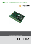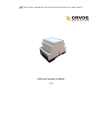
1
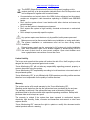
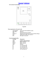
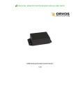
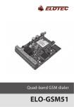
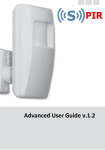
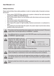
GSM Communication and Control System Lite GSM User Manual v1.1 Save a tree...please don't print this document unless you really need to www.orvos.ee / [email protected] The WEEE (Waste Electrical and Electronic Equipment) marking on this product (see left) or its documentation indicates that in the EU the product must not be disposed of together with household waste. Communication and control device Lite GSM (further referenced as the system) contains an integrated radio transceiver operating in GSM900 and GSM1800 bands. Don’t use the system where it can interfere with other devices and cause any potential danger. Don’t use the system in hazardous environment. Don’t expose the system to high humidity, chemical environment or mechanical impacts Don’t attempt to personally repair the system Any system repairs must be done only by qualified, safety aware personnel. Mains power must be disconnected before any installation or tuning work starts. The system installation or maintenance must not be done during stormy conditions. External power supply can be connected to AC mains only inside installation room with automatic 2-pole circuit breaker capable of disconnecting circuit in the event of short circuit or over-current condition. Open circuit breaker must have a gap between connections of more than 3mm. Limited Liability The buyer must agree that the system will reduce the risk of fire, theft, burglary or other dangers but does not guarantee against such events. “Orvos Monitooring OÜ” will not take any responsibility regarding personal, property or revenue loss while using the system. “Orvos Monitooring OÜ” responsibility according to local laws does not exceed value of the purchased system. “Orvos Monitooring OÜ” is not affiliated with GSM operators providing cellular services therefore is not responsible for the quality of cellular services. Warranty The system carries a 24-month warranty by the “Orvos Monitooring OÜ”. Warranty period starts from the day the system has been purchased by the end user. The warranty is valid only if the system has been used as intended, following all guidelines listed in the manual and within specified operating conditions. Receipt with purchase date must be kept as a proof. The warranty is voided if the system has been exposed to mechanical impacts, chemicals, high humidity, fluids, corrosive and hazardous environment or other force majeure factors. “Orvos Monitooring OÜ” reserves the right to update or modify this document and/or related products without a warning. www.orvos.ee / [email protected] Package Content: 1. The system Lite GSM............................ 1 pcs. 2. GSM antenna........................................ 1 pcs. 3. CD with user manual…………...............1 pcs. About User Manual This document describes remote communication system Lite GSM, its operation and installation. It is very important to read User Manual before start using the system. A quick start guide is located in first two chapters. Chapter 3 and 4 describe additional system capabilities. 3 www.orvos.ee / [email protected] Content 1. General Information 1.1 Function 1.2 Operation Description 1.3 Technical Specifications 1.4 Connector Functionality 1.5 Connection Circuit 1.6 System Installation 2. System Pre-operation and the Main Control Commands 2.1 Verification of SMS Central Number 2.2 Password Change 2.3 User Numbers 2.3.1 Saving or Changing Numbers 2.3.2 Verification of Saved Numbers 2.3.3 Deletion of Saved Numbers 2.4 Date and Time Settings 3. Additional System Capabilities 3.1 Renaming Zones and Controlled Outputs 3.2 Enabling/Disabling Zones 3.3 Info on Status SMS 3.4 Blocking Unknown Numbers 3.5 Remote Microphone Listening 3.6 Managing C1 and C2 Controlled Outputs. Timer 3.7 SMS Message Delivery to Multiple Users 4. Appendix 4.1 Restoring Default Parameters 4.2 Technical Support 4 www.orvos.ee / [email protected] 1. General Information 1.1 Function Lite GSM is a microcontroller based device used to inform users about the alarm in automatic or security systems and control one electric appliance -relay. 1.2 Operation Description Communication and control system Lite GSM works over GSM network. It works 24/7, i. e. it always reacts to the incoming signal. When the alarm siren, motion sensor, fire alarm sensor, door sensor, any other sensor or PGM output gets activated, Lite GSM system sends an SMS message and calls to the preset numbers until one of the five possible users answers the phone or rejects the call or until the call will be ended by the mobile service provider. After hanging up the phone the system turns back to the previous status. An SMS message with the name of the activated input (zone) is being sent until its successful delivery to one of the users or until it is delivered to all users. If you answer the call, the microphone gets activated for listening. After “hanging up the phone” the systems turns back to the previous status of active security. Lite GSM can control 1 electronic appliance (a relay) sending a password and a special command from a GSM phone of any of the users. You can, for example, turn on the heating, lighting, lift the gates, blinds etc. The system will ignore requests coming from unknown telephone number or SMS message with wrong password. 1.3 Technical Specifications Supply voltage: 10-24V DC Current used during the call: not more than 200mA Current used in standby mode: not more than 50mA GSM modem frequency: 900/1800 Mhz Number of “low” level (negative) inputs: 4 Number of “high” level (positive) inputs: 1 Allowable “low” level (negative) input voltage values: 0-1.6V Allowable “high” level (positive) input voltage values: 5-50V Number of outputs: 1 Output type: NO (relay) Output maximum commutating values: 1A/24V DC; 0,5A/125V AC Dimensions: 82x63x20mm Operating temperature range: -20…+55C 5 www.orvos.ee / [email protected] 1.4 Connector Functionality Fig. No 1. Short explanation of the main units GSM MODEM: SIM CARD: LED: DEFAULT: ANT: MIC: GSM network 900/1800MHz modem SIM card Light-emitting diodes indicator Connectors (D1 and D2) for restoring default settings GSM antenna SMA type connector Microphone connector Connector functionality Labeling GND +12V RELAY RELAY GND Z5 Z4 Z3 Z2 Z1 Explanation negative supply (earth) pin positive supply pin (+12V) Relay connector Relay connector Earth pin “low” level input Z5 “low” level input Z4 “low” level input Z3 “high” level input Z2 “low” level input Z1 6 www.orvos.ee / [email protected] 1.5 Connection Circuit Useful information When choosing GSM provider, it is worth inquiring whether the service is used in security application assuring fast and reliable SMS message delivery and phone call connection. To increase system reliability, it is recommended not to use prepaid SIM cards. The system would fail to send any messages upon depletion of prepaid account. Also it is recommended to disable call forwarding and voice mail. System Lite GSM and security unit GND must be connected. Inputs Z1,Z3,Z4,Z5 are connected to security unit PGM outputs if PGM are implemented as open collector circuit or any other circuit and if it commutates with GND. It is also possible to connect Z1, Z3, Z4, Z5 inputs to, for instance, motion sensor or any other sensor as well as automatics device provided the inputs are commutated with GND. Input Z2 is commutated with a “high level” impulse. Impulse duration is >600ms. Fig. No 2. 7 www.orvos.ee / [email protected] 1.6 System Installation 1. Place SIM card in the holder but make sure that SIM card PIN code is disabled. (PIN code can be disabled by putting SIM card into mobile phone and following proper menus). SIM card should not have any remaining SMS messages. 2. Connect the circuit as shown in fig. No 2. 3. The system will start in less than a minute. LED indicator should be blinking every five seconds indicating connection to GSM network. If the indicator is blinking very frequently, i. e. several times a second, it is possible that SIM card can is inserted incorrectly or PIN code request is not disabled. 2. System Pre-operation and the Main Control Commands !!! Very Important !!! In this manual the bottom crossed out _ means everywhere a blank, if writing SMS messages instead of this crossed out section you must put one blank. ХХХХ designates the password. In the end of the message should not be a blank. Call the system Lite GSM from your mobile phone and wait until the system rejects the call. In approximately 30-60 seconds you will receive an SMS message: “Please change the default password” If you received this message, go to step 2.3. If you did not receive the message, change SMS central number. Instead of calling the system you can send an SMS message to the alarm system with the following text: TEST If the telephone account is topped up and SMS central number is correct, you should soon receive a message: “SMS central number is correct” If you received this message, go to step 2.3. If you did not receive the message, change SMS central number. New central number can be entered by sending the following SMS message: XXXX_SMS_+37212345678 XXXX is a password. The default password is four zeros: 0000. Ones should be replaced with SMS central number of the provider, whose SIM card is inserted in the system. If you do not know SMS central number, you can get it from the mobile network provider. E. g. 0000_ SMS_+37212345678 Message should be sent to the number of SIM card which is placed into the system. If all went correct, the system will reply with the following message: “SMS central number has been successfully changed to +37212345678” It is possible to check SMS central number as long as the default password is not changed. SMS central number is stored in SIM card, therefore if the SIM card inserted in the security system Lite GSM was previously used in a mobile phone and SMS 8 www.orvos.ee / [email protected] messages were successfully delivered, there is no need changing SMS central number. Most often SIM card SMS central number is already entered by the operator. 2.2 Password Change All SMS commands start with a password, please memorize it. Default password is four zeros 0000, which is necessary to change. Default password can be changed by sending the following SMS message: 0000_PSW_XXXX To replace your password, send the following SMS message: YYYY_PSW_XXXX XXXX is any four digit number except four zeros. Non-numerical characters like dots, colons, spaces are not allowed. YYYY is the old system password. If you forgot the password, default password can be restored, see chapter 4.1 for more details. 2.3 User Numbers The system Lite GSM allows to pre-program up to five different mobile numbers which will have access to and control the system. NR1 is mandatory while others can be skipped. All numbers must be entered starting with international country code, e. g. national code for Estonia is 372, UK – 44. Numbers should be entered based on priority, since the system will try to contact first entered number and in case of failure will follow with second and so on. 2.3.1 Saving or Changing Numbers Send SMS message with the following text: XXXX_NR1:37211111111_NR2:37222222222_NR3:37233333333_NR4:37244444444 _ NR5:37255555555 Ones should be replaced with user numbers. Numbers don’t have to be entered in sequential order right away. E. g. use can enter first and fourth number by sending the following SMS message: XXXX_NR1:37211111111_NR4:37244444444 Or individually one number at a time: XXXX_NR3:37233333333 Numbers can be changed same way as described above. New number will overwrite old one, therefore no erasing is necessary. 2.3.2 Verification of Saved Numbers To inquire the system about pre-programmed numbers, send the following SMS message: 9 www.orvos.ee / [email protected] XXXX_HELPNR The system will reply with all pre-programmed numbers. 2.3.3 Deletion of Saved Numbers To erase NR2-NR5, send the following SMS message: XXXX_NR2:DEL_NR3:DEL_NR4:DEL_NR5:DEL E. g. XXXX_NR3:DEL The system will not allow erasing first number NR1. It can only be modified. 2.4 Date and Time Settings It is important to set correct date and time so that the system can send reports at specified times. Date and time can be set by sending the following format SMS message: XXXX_yyyy.mn.dd_hr:mi where yyyy means year; mn - month; dd - day; hr - hour; mi - minutes E. g. XXXX_2009.01.01_14:15 3. Additional System Capabilities 3.1 Renaming Zones and Controlled Outputs Manufacturer initially set the following zone and controlled output names: Zone1, Zone2, Zone3, Zone4, Zone5, CONTROLLER1 The user is free to change any of these names. The names cannot repeat or be identical to control commands. Zone names can be changed by sending the following SMS message: XXXX_Z1:NewZoneName_Z2:NewZoneName_Z3:NewZoneName_Z4:NewZoneNa me_Z5: NewZoneName Names can be changed all at once or one at a time. Maximum zone name length is 14 characters. E. g. XXXX_Z2:PGM1 Controller name can be changed by sending the following SMS message: XXXX _C1: NewControllerName Maximum controller name length is 10 characters. E. g. XXXX_C1:PUMP 10 www.orvos.ee / [email protected] 3.2 Enabling/Disabling Zones Note Manufacturer set all the zones activated, i. e. in mode ON. Useful information Few zones can be enabled/disabled together or separately one by one. Enabling Zone Any zone can be enabled by sending the following SMS message: XXXX_Z1:ON_Z2:ON_Z3:ON_Z4:ON_Z5:ON Disabling Zone Any zone can be disabled by sending the following SMS message: XXXX_Z1:OFF_Z2:OFF_Z3:OFF_Z4:OFF_Z5:OFF E. g. XXXX_Z2:OFF_Z3:OFF 3.3 Info on Status SMS The system Lite GSM can any time be inquired about signal strength and the status of zones active at the time when SMS message is sent. At the same time system test is performed. If the answer to the request has been received, it means the system finely operates. It is also useful for those using prepayment service – you can check if the credit in the account is sufficient for sending an SMS message. Send the following SMS message: XXXX_INFO The reply SMS will have following info: E. g. 2009.08.07 11:15 Signal strength satisfactory. Z1:OK/ALARM Z2:OK/ALARM Z3:OK/ALARM Z4:OK/ALARM Z5:OK/ALARM where OK means that the alarm in zone did not go on. ALARM – if it went ON. By default, this status SMS message will be sent daily at 11:00 in the morning. These parameters can be configured by sending the following SMS message: XXXX_INFO:PP.VV PP – message period in days, valid values [00-10]. VV - time when message is sent, valid values [00-23]. E. g. XXXX_INFO:01.10 means that status message will be sent every 1 day at 10:00. If PP value is 0, and VV in the range of [1-23], then periodic status messages will be sent multiple times per day, with period being specified as VV time. E. g. XXXX_INFO:0.2 means that status message will be sent every 2 hours. 11 www.orvos.ee / [email protected] To disable periodic status messages send the following SMS message: XXXX_INFO:00.00 The status messages will not be sent until enabling or restoring default parameters or receiving previously described XXXX_INFO:PP.VV SMS message. 3.4 Blocking Unknown Numbers By default Lite GSM system can be controlled from any of the pre-programmed numbers NR1-NR5. However, the user can access the system and control parameters and outputs from any number as long as password is known. To enable this feature send the following SMS message: XXXX_STR:ON To disable this feature send the following SMS message: XXXX_STR:OFF 3.5 Remote Microphone Listening Note To enable this feature it is necessary to connect microphone connector to MIC slot. The microphone is additional equipment and can be purchased separately. You can listen to what is going on in the secured premises by sending the following SMS message: XXXX_MIC The system will call back the sender of the received SMS, and upon answering the call, the user can listen to any sounds in the building. The phone call must be answered within 20 seconds otherwise the system will stop trying and return to previous state. 3.6 Managing C1 Controller. Timer. Alarm system Lite GSM contains a controller C1- a relay output REALAY. It can be used to control various electrical devices such as electric pumps, heating, lighting etc. When the controller is enabled RELAY connectors are connected. The device is turned on by sending the following SMS message: XXXX_C1:ON The device is turned off by sending the following SMS message: XXXX_C1:OFF Instead of C1 it is also possible writing a real controller name. E.g. XXXX_BOILER:OFF 12 www.orvos.ee / [email protected] Timer Alarm system Lite GSM has internal timer clock. This feature allows any output controlled output to be switched on or off for a specified time period. The following SMS command should be sent: XXXX_C1:ON/OFF:hr.mi.ss ON – output enabled. OFF – disabled hr – hours, valid values [00-24] mi – minutes, valid values [00-60] ss - seconds, valid values [00-60] It is not allowed to have all values equal zeros. Zeros it is not allowed to have all values equal E. g. to switch the pump on for 01 minutes and 23 seconds, send SMS XXXX_PUMP:ON:00.01.23 If the pump was enabled before and user want to disable it for 01 minute and 23 seconds, send SMS XXXX_PUMP:OFF:00.01.23 3.7 SMS Message Delivery to Multiple Users Upon activated alarm in security system Lite GSM SMS messages are repeatedly sent until first successful delivery to one of the users. The system starts with NR1 and if delivery fails, it follows with NR2 etc. It is also possible to set the system so that it sends SMS message to all recorded users. To enable this function send the following SMS message: XXXX_SMSALL:ON To disable this function send the following SMS message: XXXX_SMSALL:OFF 13 www.orvos.ee / [email protected] 4. Appendix 4.1 Restoring Default Parameters To restore default parameters: 1. disconnect power supply 2. short circuit (connect) connectors D1 and D2 3. connect power supply for several seconds 4. disconnect power supply 5. disconnect connectors D1 and D2 4.2 Technical Support Indication Indicator is off or not blinking Indicator blinking several times per second System does not send any SMS messages and/or does not ring Received SMS message “Incorrect Format” No sound while listening to remote microphone While listening to remote microphone outside noise heard Possible reason no external power supply circuit not properly connected blown fuse no network signal SIM card is not inserted PIN code hasn’t been disabled Sim card not active SIM card account depleted incorrect SIM central number no network signal user number is not programmed (or disabled access from unknown numbers) incorrect syntax extra space symbol left in SMS message microphone not connected microphone connection incorrect Change the position of the microphone or its lead in respect of system panel If your problem could not be fixed by the self-guide above, please contact your distributor or tech support by email [email protected]. More up to date information about your device and other products can be found at the website www.orvos.ee 14