1
US006768425B2
(12) United States Patent
(10) Patent N0.:
(45) Date of Patent:
Flaherty et al.
(54) MEDICAL APPARATUS REMOTE CONTROL
AND METHOD
(75) Inventors: J. Christopher Flaherty, Tops?eld,
MA (US); John T. Garibotto,
CharlestoWn, MA (US)
(73) Assignee: Insulet Corporation, Beverly, MA
(Us)
(*)
Notice:
Subject to any disclaimer, the term of this
patent is extended or adjusted under 35
U.S.C. 154(b) by 414 days.
(21) Appl. No.: 10/032,167
(22) Filed:
Dec. 21, 2001
(65)
Prior Publication Data
0867196
0937475
WO81/01658
WO86/06796
WO98/01071
WO99/10040
WO00/ 19887
WO99/62576
WO00/29049
WO00/ 7475 2
WO00/30705
WO00/78210
WO00/48112
WO00/61215
W00 1/52727
W00 1/ 76684
W0 02/ 20073
WO02/26282
Jul. 27, 2004
3/1998
8/1999
6/1981
11/1986
1/1998
3/1999
9/1999
9/1999
5 /2000
5 /2000
6/2000
6/2000
8/2000
10/2000
1/2001
10/2001
3/2002
4/2002
OTHER PUBLICATIONS
US 5,954,699, 9/1999, Jost et al. (Withdrawn)
US 2002/0126036 A1 Sep. 12, 2002
Web—Site Brochure dated Jan. 4, 2000. MiniMed 508.
“Doing its job. Naturally.” www.minimedcom/tiles/mmi
Related US. Application Data
(60)
EP
EP
WO
WO
WO
WO
WO
WO
WO
WO
WO
WO
WO
WO
WO
WO
W0
WO
US 6,768,425 B2
Provisional application No. 60/257,756, ?led on Dec. 21,
2000.
113.htm.
Primary Examiner—Timothy EdWards, Jr.
(51)
Int. Cl.7 ................................................ .. H04Q 9/00
(74) Attorney, Agent, or Firm—McDermott Will & Emery
(52)
US. Cl.
LLP
.. 340/870.07; 128/920; 604/132;
604/890.1; 604/892.1
(58)
Field of Search .................. .. 340/870.07; 600/300;
128/903, 820; 604/65—67, 95.01, 132, 890.1,
892.1
(56)
U.S. PATENT DOCUMENTS
1/1972 Hobbs
5/1974 Wootten et al.
1/1978 Carlson
including a medical treatment apparatus and a remote con
nicate With the local communication element of the medical
FOREIGN PATENT DOCUMENTS
4200595
19920896
0342947
0763369
A system for providing medical treatment to a patient,
treatment apparatus in a Wireless manner such that informa
tion can be transferred betWeen the local processor and the
remote processor. The remote control device also includes at
(List continued on neXt page.)
DE
DE
EP
EP
ABSTRACT
trol device. The medical treatment apparatus has a local
processor, and a local communication element connected to
the local processor, While the remote control device includes
a remote processor, user interface components connected to
the remote processor, and a remote communication element
connected to the remote processor and adapted to commu
References Cited
3,631,847 A
3,812,843 A
4,067,000 A
(57)
least tWo separate poWer supplies connected to the remote
processor.
7/1993
9/2000
5/1989
3/1997
67 Claims, 7 Drawing Sheets
5n
‘I.
i.
I
EQ IJE
V
--150
1 II
L160 (106
(105
[101
US 6,768,425 B2
Page 2
US. PATENT DOCUMENTS
4,108,177
4,151,845
4,193,397
4,211,998
4,231,019
4,268,150
4,364,385
4,373,527
4,424,720
4,435,173
4,469,481
4,475,901
4,498,843
4,507,115
4,514,732
4,529,401
4,551,134
4,559,033
4,559,037
4,560,979
4,562,751
4,585,439
4,601,707
4,624,661
4,634,427
4,678,408
4,684,368
4,685,903
4,755,173
4,781,688
4,781,693
4,801,957
4,808,161
4,836,752
D303,013
4,855,746
4,871,351
4,882,600
4,886,499
4,898,579
D306,691
4,944,659
D311,735
4,969,874
4,973,998
D315,727
5,007,458
5,045,871
5,062,841
5,109,850
5,176,662
5,178,609
5,205,819
5,213,483
5,232,439
5,239,326
5,242,406
5,244,463
5,254,096
5,257,980
5,281,202
5,308,335
5,312,337
5,318,540
5,342,313
5,346,476
5,364,342
5,411,480
5,433,710
5,452,033
8/1978
5/1979
3/1980
7/1980
10/1980
5/1981
12/1982
2/1983
1/1984
3/1984
9/1984
10/1984
2/1985
3/1985
4/1985
7/1985
11/1985
12/1985
12/1985
12/1985
1/1986
4/1986
7/1986
11/1986
1/1987
7/1987
8/1987
8/1987
7/1988
11/1988
11/1988
1/1989
2/1989
6/1989
8/1989
8/1989
10/1989
11/1989
12/1989
2/1990
3/1990
7/1990
10/1990
11/1990
11/1990
3/1991
4/1991
9/1991
11/1991
5/1992
1/1993
1/1993
4/1993
5/1993
8/1993
8/1993
9/1993
9/1993
10/1993
11/1993
1/1994
5/1994
5/1994
6/1994
8/1994
9/1994
11/1994
5/1995
7/1995
9/1995
Pistor
Clemens
Tucker et al.
Junginger et al.
Junginger et al.
Chen
Lossef
Fischell
Bucchianeri
Siposs et al.
Kobayashi
Kraegen et al.
Schneider et al.
Kambara et al.
Hayes, Jr.
Leslie et al.
Slavik et al.
Stephen et al.
FranetZki et al.
Rosskopf
Nason et al.
Michel
Albisser et al.
Arimond
Hannula et al.
Nason et al.
Kenyon
Cable et al.
Konopka et al.
Thoma et al.
Martinez et al.
Vandemoere
Kamen
Burkett
Konopka
Stacy
Feingold
Van de Moere
Cirelli et al.
Groshong et al.
Arai
Labbe et al.
Aran et al.
Michel et al.
Gates
Arai et al.
Marcus et al.
Reinholdson
Siegel
Blanco et al.
Bartholomew et al.
Ishikawa
Ross et al.
Flaherty et al.
Campbell et al.
Takai
Gross et al.
Cordner, Jr. et al.
Rondelet et al.
Van Antwerp et al.
Weber et al.
Ross et al.
Flaherty et al.
Athayde et al.
Campbell et al.
Elson
Beuchat et al.
Kriesel
Van Antwerp et al.
Balling et al.
5,492,534
5,505,709
5,507,288
5,514,096
5,533,389
5,545,152
5,551,953
5,575,770
5,576,781
5,584,813
5,630,710
5,637,095
5,643,213
5,647,853
5,660,728
5,665,065
5,665,070
5,695,490
5,702,363
5,704,520
5,726,404
5,726,751
5,741,228
5,748,827
5,755,682
5,776,103
5,779,676
5,785,681
5,785,688
5,797,881
5,800,397
5,800,405
5,810,015
5,814,020
5,839,467
5,840,063
5,845,218
5,848,991
5,851,197
5,858,005
D405,524
5,875,393
5,886,647
5,891,097
5,897,530
5,906,597
5,911,716
5,919,167
5,931,814
5,935,099
5,954,058
5,957,890
5,961,492
5,965,848
5,983,094
5,993,423
5,997,501
6,019,747
6,024,539
6,061,580
6,071,292
6,144,847
6,152,898
6,171,264
6,174,300
6,190,359
6,206,850
6,375,638
6,520,936
6,527,744
6,554,798
2/1996
4/1996
4/1996
5/1996
7/1996
8/1996
9/1996
11/1996
11/1996
12/1996
5/1997
6/1997
7/1997
7/1997
8/1997
9/1997
9/1997
12/1997
12/1997
1/1998
3/1998
3/1998
4/1998
5/1998
5/1998
7/1998
7/1998
7/1998
7/1998
8/1998
9/1998
9/1998
9/1998
9/1998
11/1998
11/1998
12/1998
12/1998
12/1998
1/1999
2/1999
2/1999
3/1999
4/1999
4/1999
5/1999
6/1999
7/1999
8/1999
8/1999
9/1999
9/1999
10/1999
10/1999
11/1999
11/1999
12/1999
2/2000
2/2000
5/2000
6/2000
11/2000
11/2000
1/2001
1/2001
2/2001
3/2001
4/2002
2/2003
3/2003
4/2003
Athayde et al.
Funderburk et al.
Bocker et al.
Hiejima
Kamen et al.
Funderburk et al.
Lattin et al. ................ .. 604/20
Melsky et al.
Deleeuw
Livingston et al.
Tune et al.
Nason et al.
McPhee
Feldmann et al.
Saaski et al.
Colman et al.
McPhee
Flaherty et al.
Flaherty
Gross
Brody
Altendorf et al.
Lambrecht et al.
Holl et al.
Knudson et al.
Kriesel et al.
Kriesel et al.
Indravudh
Joshi et al.
Gadot
Wilson
McPhee
Flaherty
Gross
Saaski et al.
Flaherty
Altschul
Gross et al.
Marano et al.
Kriesel
Falk et al.
Altschul et al.
Badger et al.
Saito et al.
Jackson
McPhee
Rake et al.
Mulhauser et al.
Alex et al.
Peterson et al.
Flaherty
Mann et al.
Kriesel et al.
Altschul et al.
Altschul et al.
Choi
Gross et al.
McPhee
Blomquist
Altschul et al.
Makower et al.
Altschul et al.
Olsen
Bader ....................... .. 600/595
Kriesel et al.
Heruth
O’Neil
Nason et al.
Mann
Kriesel et al.
Mann et al.
.............. .. 604/131
US 6,768,425 B2
Page 3
6,558,320 B1 * 5/2003 Causey et a1. ............ .. 600/300
6,645,142 B2 * 11/2003 Braig et a1. ............... .. 600/300
OTHER PUBLICATIONS
Web—Site Brochure dated Dec. 20, 1999. Applied Medical
Web—Site Brochure dated Jan. 4, 2000. SOOIL—Hornepage.
“Portable Insulin Purnp”. WWW.sooil.corn/intro2.htrn.
Web—Site Brochure dated Jan. 4, 2000. SOOIL—Hornepage.
“Portable Insulin Purnp”. WWW.sooil.corn/product2.htrn.
Technology. “508 Pump Information”. WWW.applied—rnedi
cal.co.uk/508.htrn.
Web—Site Brochure dated Jan. 4, 2000. SOOIL—Hornepage.
Web—Site Brochure dated Jan. 4, 2000. “The Glucose Sen
“Portable Insulin Purnp”. WWW.sooil.corn/product3.htrn.
sor”. WWW.anirnascorp.corn/sensorifhtrnl.
Web—Site Brochure dated Dec. 20, 1999. “The Anirnas
Web—Site Brochure dated Jan. 4, 2000. SOOIL—Hornepage.
R—1000 Insulin Purnp”. WWW.anirnascorp.corn/purnpifi
“Portable Insulin Purnp”. WWW.sooil.corn/product4.htrn.
s.htrnl.
Web—Site Brochure dated Dec. 20, 1999. “The Anirnas
Copy of International Search Report.
R—1000 Insulin Purnp”. WWW.anirnascorp.corn/purnpifi
f.htrnl.
* cited by eXarniner
U.S. Patent
Jul. 27, 2004
Sheet 1 0f 7
US 6,768,425 B2
120“,
O0 O0 O0
I
FIG. 1
1000
A
1
l////\\\\\
D S P L AY
0 0B
L
A0 9/“.
mm
0000
T00001U
(\JN
AO
m000T
OO2
FIG. 1A
U.S. Patent
Jul. 27, 2004
Sheet 2 0f 7
2/7
10oK
US 6,768,425 B2
a
(140
(170
i<-_a
FIG. 2
8120
q 11 0
I
16O)>L106
L105 (101
107
FIG. 2A
20
32
72
FIG. 2B
U.S. Patent
100
Jul. 27, 2004
Sheet 3 0f 7
US 6,768,425 B2
1
1
O2?
I
“Fri 1088-,‘
(120
(110
I
J
=
\
“450
\
\108A»
I
W
‘E
\.
“Tl
L 160106
c
\.
.2
c 105
(101
\\\\\\\\\\\\\\\\\\\\\\\\\\\\\\\\\
10K
200
23
('40
//
m
30
1 %
60>
Q, 80
Kg
(
50>
+
’Z
Z
j
I
r‘
/
/
/
201
202
29
1 7170
FIG. 3A
U.S. Patent
Jul. 27, 2004
Sheet 4 0f 7
US 6,768,425 B2
A
VOLTAG E
VT1
VT2
TIME
FIG. 4
U.S. Patent
Jul. 27, 2004
Sheet 5 0f 7
100?‘
11OTS
FIG. 5
100
K
§102
§110TS
J
I
160))
105J
106
107) L101
FIG. 5A
US 6,768,425 B2
U.S. Patent
Jul. 27, 2004
Sheet 6 6f 7
US 6,768,425 B2
{350
10$
"V353
L26
FIG. 6
100
\
25
bo O0 O0 O0
FIG. 6A
OK
FIG. 68
U.S. Patent
Jul. 27, 2004
Sheet 7 0f 7
INITIAL
CONTACT ID -
FICID FDDID
120-‘
FIG. 7
FICID FDDID
CODED
TRANSMISSION
120v
FIG. 7A
RCID FDDID
CODED
TRANSMISSION
120v
FIG. 7B
US 6,768,425 B2
US 6,768,425 B2
1
2
MEDICAL APPARATUS REMOTE CONTROL
AND METHOD
moving a slidable cover. A position of the slidable cover
determines Which device the remote control device Will
CROSS-REFERENCE TO RELATED
APPLICATIONS
control and the type of coded control signals that the remote
control device Will transmit. Other examples of devices
having multiple functions include some recent cellular
telephones, Which have been manufactured With personal
computer functions, electronic address and calendar
The present application claims priority to provisional US.
patent application Ser. No. 60/257,756, ?led on Dec. 21,
2000, Which is assigned to the assignee of the present
application and incorporated herein by reference. The
present application is related to US. patent application Ser.
No. 09/943,992, ?led on Aug. 31, 2001, Which is assigned to
10
have been developed for delivering liquid medicaments to a
patient. These infusion devices have the ability to offer
the assignee of the present application and incorporated
herein by reference.
FIELD OF THE INVENTION
sophisticated ?uid delivery pro?les accomplishing bolus
15
subcutaneous infusion of insulin to diabetic patients. Many
diabetics require insulin intake to treat their disease, and
devices that perform multiple functions, and more particu
20
functions for a user.
those patients. These pumps can deliver insulin on a con
tinuous basal basis as Well as a bolus basis as shoWn, for
25
Bass Fishing game by Radica, garage door openers, and
various other handheld electronic devices that perform spe
30
ci?c functions for a user. In recent years, technological
advances have alloWed signi?cant enhancements in such
handheld electronic devices including reduced siZe and
Weight, longer battery life, simpli?ed user interfaces, and
phone, pager, PDA or other handheld electronic device not
directly associates With the treatment of their health condi
40
devices such as those commonly supplied With televisions,
video cassette recorders (VCR’s), and DVD players. Using
45
or ultrasound, these remote control devices alloW a user to
control separate electronic equipment Without having to be
in proximity to or otherWise have access to the controls of
cases, it Would be desirable to provided a non-disposable
50
remote control device that can be used to control successive
disposable pumps.
include x-ray machines, operating tables, diagnostic
If a handheld electronic device is to be used for control
ling a medical apparatus, such as an infusion pump, certain
monitors, and drug infusion devices. The medical apparatus
remote control devices provide similar advantages to tele
vision or VCR remote control devices, obviating the need
tion. Ambulating With multiple handheld devices such as
these can be fraught With issues not the least of Which is
contusion, and the increased probability of losing one of the
devices.
Certain ambulatory infusion devices may be designed to
be of limited life or even disposable. For example, US.
patent application Ser. No. 09/943,992, ?led on Aug. 31,
2001, Which is assigned to the assignee of the present
application and incorporated herein by reference discloses a
remotely controlled, disposable infusion pump. In such
the separate electronic equipment.
Various medical apparatus can be controlled With a
remote control device as Well. Examples of these devices
information. These patients may also carry a glucose mea
suring device such as a glucometer as Well as a cellular
incorporated into the Palm Pilot personal digital assistant,
Wireless communication, such as radio frequency, infrared
located out of reach of a patient, or may be discreetly located
beneath clothing or in a carrying pouch. Since the diabetic
patient utiliZing an ambulatory infusion pump may Wish to
place the device beneath their clothing, for added comfort
and or for privacy, a remote control device is appropriate to
adjust various parameters associated With the infusion
pump, or simply to revieW pump status or other pump
35
other additional neW features and improvements. For
example, the addition of a touch screen panel, such as that
alloWs simple menu driven access to personal calendars,
address books, to-do lists and email.
Other handheld electronic devices include remote control
example, in US. Pat. No. 4,498,843 to Schneider et al.
User controlled ambulatory infusion devices are an ideal
use for a remote control since the infusion devices may be
personal digital assistants (PDA’s) such as those offered by
Palm, Inc., handheld electronic games such as the Lunker
continuous subcutaneous infusion of insulin from an infu
sion pump has been shoWn in numerous studies to greatly
improve the immediate and long term health conditions of
BACKGROUND OF THE INVENTION
Today, there are various handheld electronic devices that
are routinely carried by a large portion of the population on
a daily basis. Examples of these devices include cellular
telephones such as those offered by Nokia or Motorola,
requirements, continuous infusion and variable ?oW rate
delivery, Which can result in better ef?cacy of the drug and
therapy and less toxicity to a patient’s system. An example
of a use of an ambulatory infusion pump is for continuous
The present invention relates generally to handheld
larly to a handheld device for remotely controlling one or
more medical apparatuses in addition to performing other
functions, and built-in internet access.
User controlled ambulatory infusion devices can be an
ideal use for a remote control. Ambulatory infusion pumps
55
for a user to be proximal to or have access to the controls of
prioritiZation of performance may be desired. One such
prioritiZation, for example, relates to poWer consumption.
the medical apparatus.
As most of today’s handheld devices are poWered by a
replaceable or rechargeable battery, it may be desirable to
As handheld electronic devices and remote control
devices have become Widespread in their use, it has become
desirable to combine multiple products or functions into
regulate poWer consumption and loW battery conditions in a
specialiZed manner. In US. Pat. No. 4,514,732, for example,
Hayes shoWs poWer conservation methods for particular
60
single devices. Such devices having multiple functions do
exist, but usually the particular grouping of functions are
commands of a remote control for electronic audiovisual
equipment. When a user continually presses a key on the
remote control, such as to decrease volume, the remote
related, such as the “universal remotes” available for
televisions, VCRs, and other home audiovisual equipment
remote control devices. In US. Pat. No. 4,855,746, for
example, Stacy shoWs a multi-device remote control With an
array of keys that are exposed in pre-selected groups by
65
control is programmed to send a single command signal to
the equipment to start decreasing volume When the user
initially presses the button, and to send a single command
signal to stop decreasing volume When the button is
US 6,768,425 B2
4
3
released. Hayes’ method avoids sending a continuous stream
of signals to dictate the volume decrease in the equipment,
thus reducing the poWer consumption of the remote control.
Some electronic handheld devices and remote controls
include loW battery Warnings via an audible alert, screen
message or other visual loW battery indicator. Often, these
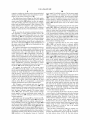
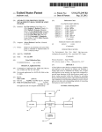
FIG. 2a is a section vieW of the remote control device of
FIG. 2 taken along line a—a of FIG. 2;
FIG. 2b is a perspective of an exemplary embodiment of
ambulatory infusion device constructed in accordance With
the present invention;
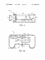
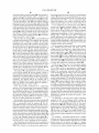
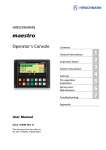
FIG. 3 is a sectional side vieW of another exemplary
devices are used until the batteries contain insuf?cient
energy to poWer the device at Which time the batteries are
embodiment of a remote control device constructed in
replaced or recharged. HoWever, for controlling medical
FIG. 3a is a sectional side vieW of another exemplary
embodiment of an ambulatory infusion device constructed in
accordance With the present invention;
treatment apparatus, such doWn time due to lack of neW 10
batteries could be very undesirable.
Accordingly, there continues to be a need for remote
control devices Which can be used With medical treatment
apparatus, such as disposable infusion pumps, as Well as
other functions. The additional functions may be related to 15
the therapy or medical treatment apparatus itself, such as a
blood glucose measuring function for the diabetic patient
the present invention;
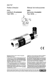
FIG. 6a is a top vieW of a remote control device of the
25
Will preferably include battery monitoring Which substan
packaged assembly of FIG. 6; and
FIGS. 7, 7a and 7b are perspective vieWs illustrating an
exemplary embodiment of a method of Wireless communi
cation according to the present invention conducted betWeen
a remote control device and a ?uid delivery device of the
SUMMARY OF THE INVENTION
present invention.
Like reference characters designate identical or corre
35
DETAILED DESCRIPTION OF EXEMPLARY
EMBODIMENTS
40
45
Set forth hereinbeloW are detailed descriptions of possible
embodiments and examples of multifunction remote control
devices, medical treatment apparatus, and systems, kits and
methods according to the present invention.
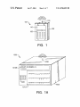
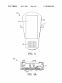
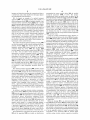
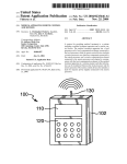
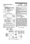
Referring ?rst to FIG. 1, there is illustrated, generally at
100, an exemplary embodiment of a multi function remote
control device constructed in accordance With the present
serial use With multiple medical treatment apparatus, such as
successive disposable infusion pumps. Also provided as an
aspect of the present invention are methods for assuring
invention. The remote control device 100 includes a visual
display 110, such as a liquid crystal display or LCD, that is
mounted to a housing 102. Preferably, the display 110 is a
proper communication betWeen a remote control device a
trated draWings.
sponding components and units throughout the several
vieWs.
poWer consumption regulations that prioritiZe poWer deliv
speci?c device to be controlled.
These aspects of the invention together With additional
features and advantages thereof may best be understood by
reference to the folloWing detailed descriptions and
examples taken in connection With the accompanying illus
packaged assembly of FIG. 6;
FIG. 6b is a top vieW of a vial of liquid medication of the
tially avoids a total loss of poWer for the medical controlling
function. Moreover, such remote control devices Will be
adapted for use With multiple medical treatment apparatus,
such as successive disposable infusion pumps.
for the medical controlling function. According to an addi
tional exemplary aspect, the multi function medical appa
ratus remote control device adapted for simultaneously or
ment of a remote control device constructed in accordance
FIG. 5a is a sectional vieW of the remote control device
multiple handheld devices. Preferably, the remote control
devices Will include poWer consumption regulations that
prioritiZe poWer delivery for the medical controlling func
ery for the medical controlling functions of the devices.
According to another exemplary aspect, the multi function
medical apparatus remote control device includes battery
monitoring Which substantially avoids a total loss of poWer
device constructed in accordance With the present invention;
FIG. 5 is a top plan vieW of a further exemplary embodi
of FIG. 5 taken along line a—a of FIG. 5;
FIG. 6 is a top plan vieW of a packaged assembly of a
medical treatment apparatus assembled in accordance With
telephone, or game functions. Desired remote control
devices, therefore, Will obviate the need for a user to carry
In response, the present invention provides a remote
control for a medical treatment apparatus that includes
functions in addition to control of the medical apparatus, as
desired. According to one exemplary aspect, the multi
function medical apparatus remote control device includes
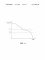
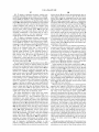
FIG. 4 is a chart illustrating voltage decay over a period
of time and loW battery level thresholds for a remote control
With the present invention;
controlling an ambulatory insulin pump. The additional
functions may be unrelated, such as PDA, cellular
tions of the devices. In addition, the remote control devices
accordance With the present invention;
touch screen display such as that included in touch screen
monitors found in various equipment including the Palm
Pilot® personal digital assistant manufactured by Palm Inc.
55
of Santa Clara Calif. Mounted to the housing 102 are
electromechanical sWitches, such as a membrane keypad
120, to alloW the user to input data or activate commands.
The remote control device 100 also includes means of
transmitting electronic signals including antenna 130 Which
BRIEF DESCRIPTION OF THE DRAWINGS
FIG. 1a is a perspective vieW of an exemplary embodi
is shoWn external to the housing 102 but is preferably
contained Within the outer surface of the housing 102.
Examples of the internal electronics and other components
of the device 100 are described in detail in subsequent
sections. The Wireless communication is accomplished
ment of a medical treatment apparatus constructed in accor
using one or more forms of electronic information transfer
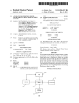
FIG. 1 is a perspective vieW of an exemplary embodiment
of a remote control device constructed in accordance With
the present invention;
dance With the present invention;
FIG. 2 is a perspective vieW of another exemplary
including radio frequency, infrared or ultrasound
65
communications, or other forms of non-Wired electronic
embodiment of a remote control device constructed in
information transfer. The device receiving the communica
accordance With the present invention;
tions Would include a receiving antenna, and electronics to
US 6,768,425 B2
5
6
interpret and otherwise transform the communicated data to
a useful form, such as that described in subsequent ?gures
and embodiments found herebeloW.
FIG. 1a depicts an example of a medical treatment
apparatus 1000 of the present invention. The example is a
representing the remote control device 100, the medical
treatment apparatus 1000, or both. The unique
identi?cations, Which can include codes, are placed in the
electronic memory of either the remote control device 100 or
the medical treatment apparatus 1000 during their manufac
turing process. After an initial communication betWeen the
device 100 and the apparatus 1000, either or both of the
unique identi?cations can be transferred betWeen the device
and the apparatus, and all subsequent communications can
include either or both of the unique identi?cations. In
electrocardiogram device 1000 With multiple displays, a ?rst
medical treatment apparatus display 1010A and a second
medical treatment apparatus display 1010B. The ?rst display
1010A is shoWn With Waveforms produced by various EKG
leads attached to a patient’s skin (not shoWn) that make up
addition, prior to acting upon commands received from the
a typical electrocardiogram of a heart patient With an inferior
remote control device 100, a check of proper identi?cation
myocardial infarction. Other examples of medical treatment
can eliminate the issue of a remote control device 100
apparatus that can be remotely controlled include one or
communicating With the Wrong medical treatment apparatus
more of the folloWing: external infusion pump, implanted
infusion pump, pacemaker, cardiac de?brillator,
neurostimulator, x-ray machine, EKG machine, diagnostic
15
preferably conducted betWeen the device 100 and the appa
ratus 1000 Wherein either or both of the unique identi?ca
tions is exchanged, folloWed by memory storage of either or
both unique identi?cations. In addition, all subsequent com
munications preferably include a con?rmation of the proper
identi?cation prior to acceptance of instructions. In some
device, glucometer, blood analyZing equipment, electrocau
tery devices, operating room tables, visual monitors and
laparoscopic remote control devices.
The medical treatment apparatus includes a housing 1002
on Which is mounted various controls including electrome
chanical sWitches 1020. Also depicted in FIG. 1a is an
instances, the remote control device 100 may doWnload a
integrated antenna 1030, shoWn exposed but preferably
contained Within the device 1000. The antenna 1030
receives signals from the remote control device 100 of FIG.
25
lish a unique identi?cation for that device. Examples of
identi?cation assignment, transfer, and con?rmation are
described in more detail in subsequent exemplary embodi
ments of the present invention.
It should be understood that the remote control device 100
may include softWare and electronic hardware for perform
ing other functions, such that the remote control device 100
is a “multi-function” device. Other functions can include
35
example.
that of a personal digital assistant, such as the Palm Pilot®.
Alternatively, the other functions of the remote control
device 100 can include one or more of an electronic game,
a barcode reader, a television or VCR remote, or a cellular
The medical treatment apparatus 1000 includes internal
electronics (not shoWn) to take the information received via
the antenna 1030, interpret the data in electronic form, and
adjust programming or other parameters accordingly. The
remotely controllable apparatus 1000 can comprise medical
devices and/or perform functions other than electrocardio
uniquely assigned identi?cation to the medical treatment
apparatus 1000, Which is then stored in the electronic
memory of the medical treatment apparatus 1000 to estab
1 so that a user can adjust various parameters, request
information, or otherWise command, control or communi
cate With the medical treatment apparatus 1000. In this
embodiment, the parameters to be adjusted can include
selection of a particular EKG lead to be displayed, adjust
ment of the display scale, or other parameters of the device
1000, for example. This remote control capability may be of
great advantage When the device 1000 is close to an active
x-ray, contained in the sterile ?eld of a medical procedure,
or contained in other biologically haZardous ?elds, for
1000, and vice versa.
A start up or initial communication mode, therefore, is
telephone, for example. Many other functions are possible.
40
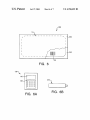
FIGS. 2 and 2a shoW another possible embodiment of a
remote control device 100 according to the present inven
tion. The remote control device is similar to the remote
control device of FIG. 1 such that similar elements have the
gram monitoring, such as an external infusion pump, an
same reference numerals. Internal components of the remote
implanted infusion pump, a pacemaker, an cardiac 45 control device 100 are contained Within a housing 102 and
de?brillator, an neurostimulator, an x-ray machine, an EKG
include a communication element 160 (referred to in
machine, blood sampling, blood analysis, a diagnostic
appended claims as “remote” communication element)
device, a glucometer, blood analyZing equipment, an elec
trocautery device, an operating room table, a visual monitor,
a laparoscopic device, and other medical equipment and
functions.
In addition to receiving electronic Wireless communica
tion via the antenna 1030, the medical treatment apparatus
1000 may also send Wireless information back to the remote
control device 1000. The information can include diagnostic
Which is used to send Wireless communication to the medi
cal treatment apparatus 1000. The Wireless communication
55
information, history information, equipment status
information, alarm status information, or other information
related to the function of the device 1000. Information can
also include device speci?c information, such as serial
may consist of electronic packets of information sent by
radio frequency, infrared, ultrasound or other Wireless forms
of communication. Also included is a poWer supply 108,
Which can be integral to the device and rechargeable by
attaching to a standard AC poWer converter. Alternatively,
the poWer supply 108 may consist of standard battery
technology such as nickel cadmium, alkaline, silver oxide or
other batteries available at convenience and other stores, and
be replaceable.
Within the housing 102 is an electronic printed circuit
board 101 having electronics 105 that includes memory 107,
number, model number or a unique identifying alphanu
meric code. Information can also include con?rmation that
a previously doWnloaded transmission from the remote
control device 100 Was properly received, or even improp
Which is shoWn as a separate electronic module but prefer
erly received, thereby triggering the remote control device
logic circuitry to perform programmable functions (referred
100 to repeat the previous transmission of electronic data.
Each transmission of electronic data betWeen the device
100 and the apparatus 1000 can include an identi?cation
ably is integral With the electronics 205. The electronics 105
also includes a microprocessor or other programmable and
65
to in the appended claims as “remote” processor). Other
components of the electronics 105 can include digital
circuitry, analog circuitry, resistors, capacitors, transistors,
US 6,768,425 B2
7
8
integrated circuits, ampli?ers, additional microprocessors,
logic circuitry, integrated circuits, programmable logic, ana
standard Wire connector, alloWing attachment to an existing
glucometer device, or a more sophisticated input device for
measuring blood glucose utiliZing optics or sensors for
log to digital converters, digital to analog converters,
multiplexors, and other semiconductor circuitry.
Preferably, a microprocessor and associated circuitry is
analyZing blood glucose strips or blood drops. Non-invasive
blood glucose technologies are commercially available or in
development by various manufacturers and developers.
Cygnus Corporation of RedWood City, Calif., for example,
manufacturers the GlucoWatch Biographer blood glucose
measuring system. The glucometer port 150 can be adapted
embedded into the electronics 105 and receives program
ming signals from a membrane keypad 120, controls the
visual display 110, and creates electronic command signals
and identi?ers to be broadcast in Wireless form via the
communication element 160. Embedded in the memory 107
of the electronics 105 or included in the microprocessor is
10
to electronically connect With a device such as the Gluco
Watch to transmit and receiving blood glucose information.
one or more microprocessor based softWare programs that
Alternatively, the information can be communicated via
de?ne, control and facilitate the operation of the device 100
Wireless technologies described herein utiliZing communi
in a predetermined manner.
cation element 160 and a transmitting or receiving element
Combined With the memory 107, Which can be one or 15 included in the glucometer.
more components integrated into electronics 105, can be
Alternatively, the glucometer port 150 can be replaced
With another input, output or combination input and output
port for alloWing attachment to other devices, performance
?xed, preprogrammed read only memory and variable, read
and Writeable memory. The memory 107 includes the pro
gramming necessary to support all functions of the device
100, including remote control of the medical treatment
of electro mechanical functions such as bar code scanning,
attachment to an information upload or doWnload device, or
apparatus as Well as the other functions such as cell phone
performance of another function. As shoWn in FIG. 2a, the
operation, a personal digital assistant, a glucometer diag
device 100 can also include a barcode reader port 140 for
connecting to a standard barcode reader pen or gun (not
nostic function, a barcode reader, and an electronic game.
The memory may also be used to store clinical therapy
information, such as diabetes care guide, a troubleshooting
guide and user manual for the medical treatment apparatus
shoWn) to simplify input of information such as drug type
25
and concentration from a drug reservoir or vial.
Alternatively, the barcode reader port 140 may include the
being remotely controlled, and a troubleshooting guide and
integrated bar code reading technology and avoid the need
user manual for the remote control device 100.
for another device. The device 100 also includes a computer
port 170 for connection to a personal computer or other
computer system to upload or doWnload information, as Well
Also included Within the housing 102 is an alarm 106
mounted to the printed circuit board 101. The alarm 106
mercially available from Star Micronics Company, Ltd. of
as offering temporary computer control of various functions
including programming or program modi?cation of the
Edison, N]. The alarm 106 is activated by the electronics
remote control device 100 itself. The computer port 170 can
preferably is an audio alarm such as a pieZo buZZer, com
include integrated Wireless communication technologies to
105 When an alert or alarm condition is encountered during
operation of the remote control device 100. Alarms may be
predicated by a condition in the remote control device 100
35
or an alarm condition detected in the medical treatment
apparatus 1000 that has been uploaded into the remote
control device 100. Examples of alarm conditions include
detection of a malfunction, loW battery conditions, or even
an alarm clock function. Examples of alarm conditions
40
uploaded from the medical treatment apparatus 1000 include
loW battery conditions, detection of malfunction, empty
reservoir in a ?uid delivery device, occlusion of How in a
?uid delivery device, out of paper condition, or out of
communication range.
The communication element 160 is also shoWn mounted
45
connect to a separate computer or computer netWork Without
the need for Wires or mechanical connection means.
Referring to FIG. 2b, the ?uid delivery device 10 is
designed to be small and lightWeight and includes a housing
20 and an adhesive attachment means (not shoWn) secured
to an external bottom surface of the housing for attaching the
device to the skin of a patient. Internal to the ?uid delivery
device 10 are a reservoir for storing the liquid medicament,
a ?uid dispenser for controlled ?uid delivery, a communi
cation element for receiving the Wireless communications
from the remote control device 100, and electronics for
receiving the electronic communication and controlling the
function of the device. On the outer surface of the housing
to the printed circuit board 101 and is electronically attached
20 is included a needle insertion septum 32 to alloW ?uid to
to the electronics 105 to feed the electronic signals, or
be placed into the reservoir of the ?uid delivery device 10
via a syringe. Alternatively, the ?uid delivery device 10 may
be pre?lled With the liquid medication at a manufacturing
site prior to the device 10 being distributed to the patient or
packets of information, to and possibly from the communi
cation element 160. Also electrically connected to the
printed circuit board 101 and the electronics 105 thereon is
the user interface components 110, 120.
caregiver, simplifying setup and reducing cost by eliminat
ing patient ?lling and obviating the need for needle insertion
In one exemplary embodiment, a medical treatment appa
ratus of the present invention comprises an ambulatory ?uid
delivery device 10, as shoWn in FIG. 2b. The ?uid delivery
device 10 is for the infusion of insulin for diabetic patients,
55
device, including skin penetrating cannula 72, Which is
inserted transcutaneously, or through the skin of a patient
into the subcutaneous tissue or other transcutaneously
and an additional function of the remote control device 100
is a glucose measurement device, or glucometer function. In
such an embodiment, the remote control device 100 includes
the necessary hardWare to measure blood glucose, such as
that taken from a blood sample, so that a diabetic patient can
accessed site, such as a vein or artery, intended for the ?uid
delivery. Alternatively, exiting the housing 20 may be a
standard Luer attachment such that a connection to a stan
dard transcutaneous infusion set can be made.
avoid the need to carry multiple handheld devices (i.e., one
for controlling the ?uid delivery device and one for mea
suring blood glucose).
Thus, as shoWn in FIG. 2, the remote control device 100
includes a glucometer port 150, Which can comprise a
septum 32.
Exiting the housing 20 is the outlet of the ?uid path of the
Preferably, the ?uid delivery device 10 is designed to be
65
loW cost and have limited life such as 2 to 3 days and
thereafter be disposable. Such an inexpensive, disposable
device is possible because the device 10 does not have an
US 6,768,425 B2
10
poWer supply”) is utiliZed for poWer. The ?rst poWer supply
expensive, complex user interface such as electromechanical
switches and visual displays, since user interface is accom
plished via the remote control device 100.
108A can continue to be depleted or may be electrically
disconnected or otherWise unused. The second poWer supply
108B is not used to supply poWer for each function, but a
reduced number of functions including remote control of a
medical treatment apparatus. Preferably, the second poWer
The ?uid delivery device 10 may be ?lled With insulin,
and associated programming of ?uid delivery device 10 and
remote control device 100 suf?cient to alloW the sophisti
cated ?oW pro?ling and bolus requirements for a diabetic
patient, such as insulin dependent or Type I diabetics. This
supply 108B provides poWer only to the remote control
function.
Determination of remaining energy level for each poWer
patient population are required to take repeated doses of
insulin just to survive, and the advantages of continuous
infusion of insulin has been Well demonstrated in scienti?c
studies.
In the case Where the remotely controlled medical treat
ment apparatus is a mass produced product, such as the
disposable infusion pump 10 described above, the remote
control device 100 may communicate With numerous infu
supply 108A, 108B can be performed by electronic voltage
detectors, electronic current detectors and integration of
values of current used, time duration measurements, mea
surements of types and duration of use, a combination of any
15
of the aforementioned techniques along With other energy
consumption and battery level detection methods knoWn to
those of skill in the art. PoWer supply 108A, 108B selection
based on poWer consumption management can be accom
plished With electronic sWitches such as transistor or other
sion pumps 10 over a period of time. For each neW infusion
pump 10 placed into operation by a user, a unique identi?
cation of the ?uid delivery device 10 can be uploaded into
semiconductors sWitching circuits.
the remote control device 100 and a unique identi?cation of
the remote control device 100 can be doWnloaded into the
It should be appreciated that the tWo poWer supplies
108A, 108B can provide poWer to separate speci?c
?uid delivery device 10.
In a preferred embodiment, the disposable ?uid delivery
provided poWer by both poWer supplies. Particularly, the
device 10 does not include a unique identi?cation, as this
may add cost to the manufacturing process. Instead, at ?rst
communication With a neW ?uid delivery device 10, the
remote control device 100 is programmed to doWnload a
unique identi?cation to the neW ?uid delivery device 10,
Which in turn is programmed to store the unique identi?ca
tion in its internal memory for the remainder of its life. All
subsequent communications betWeen the remote control
device 100 and the ?uid delivery device 10 then include the
unique identi?cation previously doWnloaded to assure
secure and proper communication betWeen the remote con
trol device 100 and the speci?c delivery device 10.
functions, or there may be particular functions that are
function of controlling a medical treatment apparatus can be
25
poWered by both poWer supplies 108A, 108B, While other
functions are limited to just one of the tWo supplies 108A,
108B, for the purpose of insuring continued, non-interrupted
remote control function. In a particular embodiment, the ?rst
poWer supply 108A supplies poWer to all functions of the
device 100, and the second poWer supply 108B only supplies
poWer to the medical apparatus controlling functions and
becomes activated only When the ?rst poWer supply 108A is
depleted to a predetermined level. Each poWer supply 108A,
35
108B can be a battery, or other energy storage means such
as a capacitor, can be user replaceable, or can be integral to
For example, the memory 107 of the remote control
device 100 automatically assigns a neW, unique identi?ca
the device and rechargeable With standard recharging means.
In one possible embodiment, the second poWer supply is
tion to each neW pump 10 at the initial communication, and
provided as a capacitor or battery that is not user
includes the unique identi?cation in each communication
replaceable, is enclosed Within the housing 102, and is not
40
With the pump to prevent the pump from receiving com
mands from other remote control devices that may be in
proximity With the pump 10. The initial communication and
accessible via removal of a battery door.
In any event, the dual poWer supply con?guration alloWs
the remote control device 100 to prioritiZe providing poWer
exchange of the unique identi?cations can be prompted by
to support the remote control of a medical apparatus versus
a user, or the remote control device 100 and the ?uid 45 other user supportive functions, such as a cellular phone
function. Since it may be greatly preferred to alloW doWn
delivery device 10 can be programmed to automatically
exchange identi?cations upon initial communications.
time With the cellular function versus any doWn time With
the control of the medical treatment apparatus, the dual
poWer supply control functions described herein avoid a user
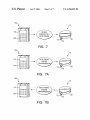
FIG. 3 depicts a cross sectional side vieW of another
possible embodiment of a remote control device 100 of the
present invention. The remote control device is similar to the
remote control device of FIG. 2 such that similar elements
have the same reference numerals. The remote control
device 100 of FIG. 3, hoWever, further includes multiple
poWer supplies to prevent inadvertent poWer outage for
portions of the device 100 relating to control of a medical
treatment apparatus.
Removable from the housing 102 is a battery door 111,
inadvertently or accidentally depleting a battery supply
using a function such as a phone call and then being unable
to control their medical apparatus.
It is a great advantage for the user to be able to combine
a remote control of a medical apparatus With other functions
55
Which alloWs access to ?rst poWer supply 108A and second
poWer supply 108B, Which can comprise replaceable bat
teries. Preferably, at least one of the ?rst poWer supply 108A
and the second poWer supply 108B is alWays used to poWer
each function of the remote control device 100. When the
such as cellular phones, personal digital assistant, or other
handheld electronic device. HoWever, if use of the non
medical function depletes the battery to a loW enough level
to prevent control of the medical apparatus, the multi
function device may lose its appeal. The poWer supply
control circuitry described herein, therefore, prevents non
determining remaining energy life, the second poWer supply
medical usage of remote control device 100 that Would
deplete the batteries to a point of loss of the medical
apparatus remote control function.
FIG. 3a shoWs a ?uid delivery 10 to be remotely con
trolled by a remote control device 100 of the present
invention. The ?uid delivery device of FIG. 3a is similar to
108B (referred to in the appended claims as “dedicated
the ?uid delivery device of FIG. 2b. The ?uid delivery
energy remaining in the ?rst poWer supply 108A (referred to
in the appended claims as “general purpose poWer supply”)
decreases to a certain predetermined level or other means of 65
US 6,768,425 B2
11
12
device 10 includes recessed housing 200 Which includes a
recessed surface 29 positioned Within a continuous ring
the remote control device and received by a communication
element 60 (referred to in the appended claims as a “local”
adhesive layer 201. Located beneath housing adhesive layer
201 may be secondary housing adhesive layer 202 such that
if the housing adhesive layer 201 loses suf?cient adhesive
properties and is removed, the secondary adhesive layer 202
communication element), shoWn in FIG. 3a. Preferably, the
is available to attach, or reattach, the ?uid delivery device 10
to skin of a patient. Preferably, the siZe of the ?uid delivery
device 10 is small to alloW comfortable adhesive attachment
to the patient’s skin. Based on the siZe and shape of recessed
housing 200 it may be desirable for the outer shell to ?ex
after adhesive attachment to the patient’s skin. Included at
various locations along recessed housing 200 are housing
?uid delivery device 10 is a loW cost disposable insulin
pump, and includes no user interface components and can
only be interfaced With by a user via a remote control device.
In one embodiment, the communication element 60 both
receives and transmits electronic signals to the remote
control device 100. Information transmitted by the ?uid
10
delivery device 10 may include alarm conditions, program
ming history, infusion history, con?rmation of
is designed and constructed to be compatible With the liquid
programming, handshaking or other communication con
?rming codes, or other electronic controls or information
transfer. Information can be transferred With standard Wire
less technologies such as radio frequency or infrared, and
include standard handshaking or other communication con
medication, such as insulin, to be infused. In a preferred
?rmation protocols such as those employed in commercially
embodiment, the reservoir 30 is pre?lled With the liquid
available modems and fax machines.
FIG. 4 is a graph of voltage versus time of a poWer supply
for a handheld electronic device. The decay curves of
voltage over time for typical use or typical battery drain is
shoWn. Referring also to FIG. 3, such measurements of the
general purpose poWer supply 108A can be used to by the
remote control device 100 to determine When the dedicated
poWer supply 108B is used to supply poWer to the remote
control device 100. For example, the internal electronics 105
hinged sections 23, to alloW ?exing.
Included Within the housing 200 is a reservoir 30 Which
15
medication, hoWever the entire reservoir can be inserted by
the user if in the form of a pre?lled cartridge, not shoWn, or
the ?uid delivery device 10 may include medication ?ll
means, such as a needle penetrable septum in ?uid commu
nication With the reservoir 30, also not shoWn. The reservoir
30 is in ?uid communication With a dispenser 40, Which is
used to precisely control the amount of ?uid to exit the ?uid
25
delivery device 10 via exit port assembly 70. FIG. 3a depicts
an exit port assembly 70 including a standard attachment
can measure the energy level, such as a voltage level, of the
such as a Luer connector 71 Which can be attached to a
?rst poWer supply 108A and When the level decreases beloW
a certain value, employ the second poWer supply 108B.
In FIG. 4, the voltage curve is for the general purpose
poWer supply 108A of FIG. 3. A second voltage threshold
VT2 is shoWn in FIG. 4 and represents a predetermined
energy level at Which the dedicated poWer supply 108B is
transcutaneous infusion set (not shoWn) for transcutaneous
delivery of the liquid medication. Alternatively, the Luer
connector 71 can be replaced With a transcutaneous cannula
assembly that is integrated into exit port assembly 70 and
obviates the need for the transcutaneous infusion set.
The dispenser 40 controls ?uid ?oW from the reservoir 30
to the exit port assembly 70, and can comprise a linear or
35
rotary peristaltic pump if the reservoir 30 is not pressuriZed.
Alternatively, the dispenser 40 can comprise an electrody
namic pump, a displacement pump or other ?uid pumping
mechanism. The dispenser 40 can be combined With a
separate metering element to achieve the proper volume of
?uid to be infused, or the dispenser 40 can be adapted to
independently infuse the correct volumes.
If the reservoir 30 is pressuriZed, by a compressing
member or by being enclosed in a gas pressuriZed chamber
for example, the dispenser 40 can be adapted to simply
meter the ?uid from the reservoir. The dispenser 40 can then
40
conditions remain unchanged so that the dedicated poWer
supply 108B remains connected. Such a method of differ
entiating a voltage level slightly above a threshold if the
level had previously decreased beloW the threshold is knoWn
as a hysteresis function or method. Once a threshold level is
replacement or recharge, the actions are reversed or a neW
action performed.
An alternative to the dual poWer supply construction
presented in FIG. 3 and discussed above, includes the
creation of tWo preset energy thresholds for use With the
single poWer supply 108 illustrated in FIG. 2a. The remote
55
control device 100 further includes means for measuring a
threshold such as a ?rst voltage threshold VT1, illustrated in
FIG. 4. When the energy level in the single poWer supply
108 decreases to beloW the ?rst voltage threshold VT1,
valves or solenoid actuators, motors or micro motors, or
other electromechanical components requiring electrical sig
nals for activation, poWer or both. PoWering the dispenser 40
and the electronic microcontroller 50 is a poWer supply 80,
Which is preferably a battery. If the ?uid delivery device 10
is a loW cost disposable advice, the poWer supply 80 is
preferably integral to the ?uid delivery device 10 to thereby
functions of the device 100 not related to the remote control
of the medical treatment apparatus are deactivated or shut
doWn.
For example, a non-medical function such as cellular
telephone use, may be of a de-prioritiZed nature as compared
avoid the need for a user to purchase and insert batteries.
The ?uid delivery device 10 of FIG. 3a is controlled by
means of detecting When the voltage of the general purpose
poWer supply 108A ?rst drops beloW the second voltage
threshold VT2, such that if the voltage increases above the
second voltage threshold VT2 thereafter, the battery control
crossed, minor measurement perturbations above the thresh
old do not change the resulting actions from the initial
crossing. When the voltage exceeds the threshold by a more
signi?cant, preset level, such as that caused by neW battery
include an accumulator chamber and valves before and after
the accumulator chamber to dispense ?xed pulses of ?uid.
Alternatively, the dispenser 40 can be adapted to control
?oW rate via ori?ce constriction and expansion.
Still referring to FIG. 3a, an electronic microcontroller 50
(referred to in the appended claims as a “local” processor) is
used to electronically control the dispenser 40. The dis
penser 40 can include electrically driven propulsion means,
electrically activated remote control devices such as pieZo
utiliZed. The measurement electronics 105 may include
to control of a medical treatment apparatus such as a ?uid
65
delivery device for the delivery of insulin to a diabetic
a remote control device, such as the remote control devices
patient. Therefore, the remote processor 105 is programmed
100 of FIGS. 2 and 3, via Wireless electronic signals sent by
to shut doWn the cellular telephone function of the remote
US 6,768,425 B2
13
14
control device 100 When the available power of the single
poWer supply 108 decreases beloW the ?rst voltage threshold
data analysis can be used, integrated, or otherWise analyZed
to determine Which functions to enable and disable, or hoW
to distribute poWer among the functions.
Another exemplary embodiment of a remote control
device 100 of the present invention is shoWn in FIGS. 5 and
5a. The device of FIGS. 5 and 5a is similar to the device of
FIGS. 2 and 2a such that similar elements have the same
VT1 in order to alloW one or more hours of control of the
?uid delivery device.
In addition, a possible embodiment of the remote control
device 100 can include an override function that alloWs
continued use of the non-medical control function(s) if
desired by a user. In cases of emergency, for example, the
cellular phone function of the device 100 may be of such
importance that continued use of the phone function at the
risk of deactivation of the medical control function due to
10
Also included in the remote control device 100 of FIGS.
5 and 5a is an electronic communication port 171. The port
depletion of the single poWer supply 108 may be acceptable.
In such an embodiment, the remote control device 100 might
require the user to override the deactivation by con?rmation
via the keyboard 120 or other user input means of the device
100 to reactivate the phone function. The override may be
temporary or permanent, and may trigger a second level of
171 can be a simple modem for connection to an outside
computer or internet system via a phone line, or an Ethernet
15
connector for connection to a netWork, the internet, or other
Wired electronic communication channel. The communica
tion port 171 can facilitate other forms of electronic infor
mation upload or doWnload, most particularly information
remaining energy level thresholds (e.g., VT2) to be
employed for the deactivation of the phone function When
the available poWer of the single poWer supply 108
Which can be sent to the user to help manage, troubleshoot
and otherWise use the medical treatment apparatus being
controlled. The information can be uploaded or doWnloaded
from a clinician or other health care giver, the manufacturer
of the remote control device 100, or the manufacturer of the
decreases beloW the second voltage threshold VT2.
The remote control device 100 may include means of
alerting the user prior to deactivation of any functions. This
alert may be accomplished With audio or visual information
made available to the user by detection of particular energy
reference numerals. The device of FIGS. 5 and 5a, hoWever,
includes a “touch screen” display 110TS for alloWing user
input as Well as for displaying information.
25
states of the one or more poWer supplies. For example, a
voltage threshold just above the ?rst voltage threshold VT1
may cause the alert condition to occur, thus notifying the
user that certain functions are near deactivation, similar to a
medical treatment apparatus being remotely cointrolled.
Alternatively, all of these upload and doWnload commu
nications can be accomplished via Wireless technologies
accepted by communication element 160 contained Within
the remote control device 100. In this Wireless scenario,
communication can be sent via satellite or other global or
loW battery Warning condition found in many battery poW
ered devices. In addition, multiple thresholds can be detect
able by the electronics of the remote control device 100 such
near global communication, updating each applicable
that one or more loW battery conditions, as they relate to
individual or groups of speci?c functions, can be used to
information, text or user manual information, or other data
stored Within the memory 107. The information can be
selectively deactivate individual or groups of speci?c func
remote control device 100 With neW programming
35
tions in a prioritiZed manner. For example, a remote control
device 100 that includes medical treatment apparatus
control, cellular telephone function and personal digital
assistant function, may include thresholds for all three stated
functions and deactivate the PDA function ?rst and then the
cellular function prior to the medical treatment apparatus
remote control device function.
It should be considered in the scope of this application
that there are various techniques for determining the amount
of energy remaining in one or more poWer supplies. Voltage
detection is common and the energy dissipation curves of
40
45
embodiment, the ?uid delivery device 10 of the packaged
assembly 350 can include an integral transcutaneous infu
sion set. At least the transcutaneous infusion set and ?uid
more poWer supplies can be used to achieve similar
55
function availability. In other Words, one or more batteries
can be employed utiliZing one or more remaining energy
path portions of the device 10 are steriliZed to prevent
contaminants from passing through the skin of a patient
using the device 10.
Also shoWn in FIG. 6, the ?uid delivery device 10 is
provided With an information barcode 26. Such an informa
measurements, preferably voltage thresholds. Based on
these thresholds, additional poWer supplies can be brought
tion barcode 26 may be utiliZed by various systems for
cataloging or otherWise recording information about the
?uid delivery device 10. The remote control device 100 of
on line and or particular functions made no longer available
or deactivated, to insure continued operation of the medical
apparatus apparatus control function.
In addition to discreet energy level measurements, such as
ments and measurements, and other multiple information
by DuPont Corporation of Wilmington, Del. The assembly
facilitate sealed attachment to the assembly tray 353.
The sealed tray construction alloWs the ?uid delivery
device 10 to be steriliZed utiliZing various methods, includ
ing ethylene oxide steriliZation. In one possible
spirit of this application. Examples of one or tWo poWer
supply embodiments have been described, hoWever three or
voltage level measurements, a history of activity potentially
including current measurements, history of battery replace
function is to send, and potentially receive Wireless com
munications to medical apparatus treatment apparatus 1000.
FIG. 6 shoWs a packaged assembly 350 Which includes a
?uid delivery device 10 similar to the ?uid delivery devices
of FIGS. 2b and 3a. The ?uid delivery device 10 is packaged
in an assembly tray 353, Which can be constructed of a
steriliZable material such as PETG, or polycarbonate, and is
seal With an assembly lid 352, Which can be constructed of
steriliZable material such as Tyvek® Wrap material supplied
lid 352 may include an adhesive on its bottom surface to
batteries of various technologies can be predicted quite
reliably. Other techniques can be used in conjunction With or
independent of voltage detection Without departing from the
outcomes, and a single poWer supply may consist of more
than one battery, connected in series or in parallel or both.
In addition, multiple energy thresholds can be measured in
any or all of the poWer supplies to change the status of
received by communication element 160 Whose primary
65
FIG. 6a can be provided With a bar code reader function, and
can be programmed to upload the information barcode 26
data to perform an initialiZation function described here
above. The information barcode 26 data can be unique for
each ?uid delivery device 10 and include a unique ?uid
delivery device identi?cation, or other unique and non
US 6,768,425 B2
15
16
unique information such as manufacturing date, serial
number, type of medication preloaded, concentration of
include codes that signify the initiation, and subsequent
communications may include codes that not only signify not
being the initial communication, but also include informa
tion calculated, uploaded, doWnloaded or otherWise deter
medication, physician identi?cation, patient identi?cation,
or other clinical or non-clinical information. The use of
information barcode 26 containing unique device
information, versus including such unique information in the
mined during or as a result of the initial communication.
electronic memory of the ?uid delivery device 10 may be
internal programming by manufacturing is standardiZed, or
more ef?cient and cost effective for mass production of the
non-unique, to reduce manufacturing costs. At the initial
communication With the remote control device 100, a unique
identi?cation is transmitted to the ?uid delivery device 10,
received by the ?uid delivery device 10, and stored in the
memory of the ?uid delivery device 10. In a preferred
embodiment, the ?uid delivery device 10 can transmit
signals as Well as receive, to provide tWo-Way communica
tion With the remote control device. Receipt of the assigned
?uid delivery device identi?cation can be transmitted by the
?uid delivery device 10 to the remote control device 100 to
con?rm the initialiZation and subsequent communications.
In a preferred embodiment, all ?uid delivery device 10
?uid delivery device 10, especially in designs and construc
tions Where the device is to be of extreme loW cost for
limited life or disposable use.
10
A preferred packaging construction to the tray and lid
described above Would be a sealable pouch, common to the
medical apparatus industry. The pouches usually consist of
a rectangular piece of breathable material such as Tyvek,
Which is sealed to a piece of clear ?exible plastic, such as
15
thin Mylar. The pouch construction can be steriliZed in
similar fashion to the tray and lid packaging, and is generally
of less cost to manufacture Without providing the rigid
The remote control device 100 memory may communi
cate With many ?uid delivery device 10 over the life of the
remote control device 100, and thus a matrix of ?uid
protection of the tray packaging.
FIG. 6b depicts a top vieW of therapeutic ?uid supply 250.
Therapeutic ?uid supply 250 may include a glass or plastic
vial, and may be ?lled With various types of one or more
liquid medications such as insulin. The therapeutic ?uid
supply 250 may be loaded, like a cartridge, into a properly
designed and adapted ?uid delivery device 10, or the con
tents of therapeutic ?uid supply 250 may be transferred,
through interlocking ?uid connection or via syringe and
needle, into ?uid delivery device 10 at a integral injection
port, not shoWn. Alternatively, ?uid delivery device 10 may
25
delivery device identi?cations Would be maintained in the
memory of the remote control device 100 to avoid duplica
tion of identi?cations. In addition, the remote control device
100 may transmit a unique identi?cation for itself to the ?uid
delivery device 10, to insure that in all subsequent
communications, signals are received by the correct remote
control device. For practical purposed, the unique identi?
cation doWnloaded to the ?uid delivery device 10 may
include a unique pre?x, suf?x or other part identifying the
be pre?lled With the liquid medication obviating the need for
remote control device in a unique Way, as Well as a unique
therapeutic ?uid supply 250.
additional identi?cation code, Whereby the combined codes
is the unique identi?cation for the ?uid delivery device, and
Various Ways of combining devices of the present inven
tion into appropriate infusion kits can include packaging
multiple units of one type of device With a single other type
of device. For example, a single remote control device 100
35
of the present invention can be provided as a kit With thirty
to one hundred loW cost, disposable ?uid delivery devices 10
of the present invention. Typical kit con?gurations include a
single remote control device 100 packaged With multiple
the entire unique code is checked at each transmission to
insure proper correlation of both devices. In the preferred
embodiment in Which the ?uid delivery device 10 can
transmit information to the remote control device, the
unique identi?cation can be included in ?uid delivery device
10 transmitted communications as Well.
40
delivery device packaged assemblies 350, each containing
In an alternative embodiment, the ?uid delivery device 10
may be manufactured With a unique identi?cation, such as a
?uid delivery device 10. If the ?uid delivery device 10 is not
serial number, in its electronic memory. In this
?lled With liquid medication, therapeutic ?uid supply 250
con?guration, the ?uid delivery device 10 Would transmit
are also packaged in the infusion kit. In addition to the above
components or products, other components or products may
be packaged in the infusion kit such as user instructions,
batteries for the remote control device 100, multiple batter
45
the unique identi?cation to the remote control device 100 in
the initial communication in addition to the remote control
device 100 transmitting its unique identi?cation to the ?uid
delivery device 10, each device holding both unique codes
ies for the ?uid delivery devices 10, syringes, needles,
transcutaneous penetration site preparation materials, and
other peripheral devices. In addition, blood glucose measur
in electronic memory, and checking for proper device com
munication at each transmission.
FIG. 7 depicts the initial communication betWeen devices
ing supplies such as ?nger prick devices, test strips, diag
Where a remote control device identi?cation “RCID”, and a
nostic devices such as glucometers, and other blood glucose
measurement accessory devices may be supplied in the kit.
?uid delivery device identi?cation “FDDID” are transmitted
from remote control device 100 to the ?uid delivery device
10. As described hereabove, the unique identi?cation can
simply be a combination of the tWo device identi?cations
With or Without additional coded information. The ?uid
One or more backup remote control devices 100 can also be
included With the kit. Many variations of kits are possible.
FIGS. 7, 7a and 7b depict diagrammatic vieWs of an
embodiment of a remote control device 100 communicating
55
delivery device identi?cation FDDID can be generated by
the remote control device 100 or already preprogrammed
into ?uid delivery device 10 at the time of manufacturing. In
With an embodiment of a ?uid delivery device 10 or the
present invention. FIG. 7 depicts an initial communication
betWeen the remote control device 100 and the ?uid delivery
this instance, the code may be included in random access or
RAM memory or in read only memory or ROM memory. In
the case Where the unique identi?cation is doWnloaded from
device 10 Wherein the remote control device 100 sends a
Wireless electronic information signal to the ?uid delivery
device 10. The internal electronics of the ?uid delivery
the remote control device 100, the unique identi?cation
device are programmed to detect an initial communication,
and from then on only accept communications that include
information different than information contained in the
initial communication. The initial communication may
65
Would be stored in RAM. Alternatively, a label containing a
barcode, as described hereabove, can be read by the remote
control device 100 and subsequently doWnloaded into the
electronic memory of the ?uid delivery device 10.
US 6,768,425 B2
17
18
FIG. 7b depicts a subsequent electronic, Wireless com
munication including the remote control device identi?ca
tion RCID and including the ?uid delivery device identi?
cation FDDID in addition to other programming, control,
delivery device 10 may involve special passWords, keys, or
other special functions or actions to alloW the ?uid delivery
device 10 to accept the commands from the neW remote
control device 100. Conversely, the remote control device
100 Will include programming to alloW it to communicate
command or other information sent from the remote control
With many ?uid delivery device 10, hoWever, perhaps not
device 100 to ?uid delivery device 10. Prior to action related
to the command codes sent, a check Would be performed to
more than one at a time. The remote control device 100 may
con?rm completion and accuracy of the message, using
include programming such that after an initial
checksum or other appropriate techniques, as Well as a check
that the proper remote control device 100 had sent the
communication, only that particular ?uid delivery device 10
can be controlled until another initial communication infor
mation transfer is performed With a neW ?uid delivery
information to the proper ?uid delivery device 10. After
acceptable con?rmations, a return signal may be sent to
device 10, after Which the previous ?uid delivery device 10
may or may not be able to be controlled by that remote
acknowledge acceptance, and then appropriate actions
Would take place in the ?uid delivery device 10.
FIG. 7c depicts a subsequent electronic, Wireless com
munication including the remote control device identi?ca
15
tion RCID and including the ?uid delivery device identi?
cation FDDID in addition to other programming, control,
remote control device 100 but prevent actual infusion pro
gramming or other controls.
The remote control device may include programming or
command or other information sent from the ?uid delivery
device 10 to remote control device 100. Prior to action
related to the command codes sent, a check Would be
command sets Which are available only to certain users such
as the patient, clinician, diagnostic technician, clinical
performed to con?rm completion and accuracy of the
message, using checksum or other techniques knoWn to
technician, product technician, or other unique user. Each of
those of skill in the art, as Well as a check that the proper
?uid delivery device 10 had sent the information to the
proper remote control device 100. After acceptable
con?rmations, a return signal may be sent to acknowledge
25
the functions may be passWord or otherWise controlled to
limit access. In all instances, the remote control device 100
Will include at least a transmitter, and a medical treatment
apparatus, such as the ?uid delivery device 10, Will include
acceptance, and then appropriate actions Would take place in
at least a receiver. In a preferred embodiment, remote
control device 100 further includes a receiver, and the ?uid
delivery device 10, further includes a transmitter.
Various methods of using remote control device 100 are
the remote control device 100.
In a preferred embodiment, the ?uid delivery device 10 is
an insulin delivery device for diabetic patients. The ?uid
included in the present invention and described above. The
method of programming the ?uid delivery device 10 With
delivery device is disposable, used by the patient for three or
less days, and requires the remote control device 100 for
programming and use. It is imperative that proper commu
nications are con?rmed including con?rmation that the
proper remote control device 100 is commanding the proper
control device 100. Obviously, it may be desirable to obtain
information from a previously used ?uid delivery device 10,
so programming may alloW information transfer, or upload
from the previously used ?uid delivery device 10 to the
35
remote programmer 100 as Well as control of other forms of
medical treatment apparatus 1000 are described. Also rel
evant is the ability to update the internal programming of
?uid delivery device 10. These patients may be part of
either the ?uid delivery device 10 or the remote control
patient groups, attend diabetes conferences, or otherWise be
in the presence of one or multiple patients Who utiliZe the
same system. Protocols such as that disclosed in this appli
cation are imperative to prevent undesired programming
changes of any type. In addition, the remote control device
100 and or ?uid delivery device 10 may include a proximity
device 100 by the corresponding device. Methods of creat
ing and mapping unique alphanumeric identi?cations for a
40
apparatus have regarded a ?uid delivery device 10, many
alarm or alarms such that When the distance betWeen the
remote control device 100 and ?uid delivery device 10
medical treatment apparatus, such as the ?uid delivery
device 10 of the present invention, and the remote control
device 100 have been described.
While the majority of description for a medical treatment
45
exceeds a particular amount, one or both devices produce an
audible and or tactile, such as vibrational, alarm.
The unique identi?cation of either device may include
alpha numeric designators or simple binary digits, or a
binary representation of a more sophisticated code. The
other types of medical apparatuses are applicable for use
With a remote control device of the present invention 100.
The value of the multi function remote control 100 is
enhanced in situations Where the user is more likely to carry
the remote control device in their daily routine, or as part of
transmissions may include digital or more sophisticated
their job. This condition is obvious With the diabetic patient
for continuous infusion of insulin, but also found in patients
Waveforms, each including the unique codes representing
and hospital Workers Who need to control medical treatment
either or both the medical treatment apparatus devices. The
apparatus for a long portion of their day, potentially their
Working day. The advantage of other multiple uses makes
the requirement of carrying and otherWise maintaining the
?uid delivery device 10 programming can be made such that
after the initial communication With a remote control device 55
100, the ?uid delivery device Will only accept command
remote control device seem less burdensome, and may
codes from transmissions received With that remote control
reduce the need to carry around a separate device such as a
device 100 unique identi?cation, remote control device
identi?cation RCCID. Alternatively, the ?uid delivery
device 10 programming may alloW control from multiple
remote control device 100, With more complex acceptance
PDA, cellular phone or other handheld electronic device.
The methods and design features described in this applica
tion that relate to disposable ?uid delivery devices, can be
applied to non-disposable ?uid delivery devices as Well as
other medical apparatus and should not in any Way limit the
scope of the remote control device 100 or the applicable
schemes. The remote control device 100 may include pro
gramming and unique identi?cations that identify master
systems.
remote control devices, or remote control devices that are
used for diagnostic, troubleshooting, clinician, or other
purposes. Control of a ?uid delivery device 10 by a remote
control device 100 that did not initialiZe that particular ?uid
65
Although exemplary embodiments of the invention have
been shoWn and described, many changes, modi?cations and
substitutions may be made by those having ordinary skill in
US 6,768,425 B2
19
20
the art Without necessarily departing from the spirit and
2. A system according to claim 1, Wherein the medical
scope of this invention. For example, a poWer supply has
treatment apparatus includes a unique identi?cation
included in all communications betWeen the medical treat
ment apparatus and the remote control device.
often been described as a battery, such as a silver oxide
battery. If tWo or more silver oxide batteries Were connected
in series to increase voltage or if placed in parallel to
increase the available supply of current, they may be con
sidered as a single poWer supply. Combinations of batteries,
capacitors and other energy storage devices in series or
parallel, acting either as a single poWer supply or as multiple
poWer supplies can be made Without departing from the
3. A system according to claim 1, Wherein the remote
control device includes a unique identi?cation included in
all communications betWeen the medical treatment appara
tus and the remote control device.
4. A system according to claim 1, Wherein the medical
treatment apparatus comprises one of an external infusion
pump, an implanted infusion pump, a pacemaker, a cardiac
de?brillator, a neurostimulator, an x-ray machine, an EKG
scope of this application. Also, various means of poWer or
energy level detection have been described, such as voltage
level detection, but various other means of measuring,
monitoring or otherWise calculating remaining energy can
be used. Also, various methods of creating and storing
electronic unique identifying codes have been described,
15
machine, a diagnostic device, a glucometer, a blood
analyZer, an electrocautery device, an operating room table,
a monitor, and a laparoscopic controller.
5. A system according to claim 1, Wherein the remote
hoWever other means of coding transmissions to create
control device is also adapted to function as at least one of
unique identi?cations that can be uploaded and doWnloaded
to accomplish con?rmed communication betWeen the
a cellular phone, a personal digital assistant, and an elec
tronic game.
remote control device 100 and medical treatment apparatus
6. A system according to claim 1, Wherein the remote
control device further includes electronic memory storing a
user manual for the medical treatment apparatus.
1000 may be employed.
Also, the ?uid delivery device of this invention is
intended to be loW cost, light Weight, simple to use and
potentially disposable by removing a majority of the user
7. A system according to claim 1, Wherein the Wireless
communication betWeen the remote control device and the
interface, including electromechanical sWitches, from the
?uid delivery device, and including a separate remote con
trol device to replace those functions. A reservoir, ?uid
dispenser, transcutaneous ?uid administration means, solid
25
control device further includes an alarm connected to the
remote processor and the remote processor is programmed
to activate the alarm upon a measured poWer level of a ?rst
state electronics and Wireless communications are included
in the ?uid delivery device to perform its intended function.
While various means of reservoir construction, pressuriZa
tion means, ?uid pumping means, ?uid metering means,
transcutaneous delivery, electronic control and Wireless
communications have been discussed in this application,
of the separate poWer supplies failing beloW a predetermined
minimum poWer level.
9. A system according to claim 8, Wherein the alarm
comprises an audible alarm.
10. A system according to claim 1, Wherein the remote
processor is programmed to receive a unique identi?cation
alternatives to each of these areas can be made Without
departing from the spirit of the invention.
In addition, Where this patent application has listed the
35
steps of a method or procedure in a speci?c order, it may be
40
order-speci?c unless such order speci?city is expressly
stated in the claim.
What is claimed is:
1. A system for providing medical treatment to a patient,
comprising:
for the medical treatment apparatus during a ?rst commu
nication With the medical treatment apparatus.
11. A system according to claim 10, Wherein all subse
possible (or even expedient in certain circumstances) to
change the order in Which some steps are performed, and it
is intended that the particular steps of the method or proce
dure claims set forth herebeloW not be construed as being
medical treatment apparatus is radio frequency signals.
8. A system according to claim 1, Wherein the remote
45
quent communications betWeen the medical treatment appa
ratus and the remote control device include the unique
identi?cation for the medical treatment apparatus.
12. A system according to claim 1, Wherein the remote
processor is programmed to send a unique identi?cation for
the remote control device during a ?rst communication With
the medical treatment apparatus.
13. A system according to claim 12, Wherein all subse
quent communications betWeen the medical treatment appa
ratus and the remote control device includes the unique
identi?cation for the remote control device.
A) a medical treatment apparatus including,
a local processor, and
a local communication element connected to the local
processor;
14. A system according to claim 1, Wherein the separate
poWer supplies include a general purpose poWer supply and
B) a remote control device separate from the medical
a dedicated poWer supply and the remote control device is
treatment apparatus and including,
adapted to use the dedicated poWer supply only for functions
related to communications betWeen the medical treatment
a remote processor,
apparatus and the remote control device.
user interface components connected to the remote
55
15. A system according to claim 14, Wherein the general
processor,
a remote communication element connected to the
purpose poWer supply comprises a battery.
16. A system according to claim 14, Wherein the general
purpose poWer supply is user-replaceable.
17. Asystem according to claim 14, Wherein the dedicated
poWer supply comprises a capacitor.
18. Asystem according to claim 14, Wherein the dedicated
poWer supply is unitarily integrated as part of the remote
remote processor and adapted to communicate With
the local communication element of the medical
treatment apparatus in a Wireless manner such that
information can be transferred betWeen the local
processor and the remote processor, and
at least tWo separate poWer supplies connected to the
remote processor Wherein the separate poWer sup
plies include a general purpose poWer supply and a
dedicated poWer supply and the remote control
device is adapted to use the dedicated poWer supply
only for a subset of the functions of the remote.
65
control device.
19. A system according to claim 14, Wherein the remote
processor is programmed to use the dedicated poWer supply
upon a measured poWer level of the general purpose poWer
supply falling beloW a predetermined minimum poWer level.